Manitou MRT 1440 ST3B (400°), MRT 1640 ST3B (400°), MRT 1840 ST3B (400°-360°). MANUALE D’ISTRUZIONI - 10
 

  Index      Manuals     Manitou MRT 1440 ST3B (400°), MRT 1640 ST3B (400°), MRT 1840 ST3B (400°-360°). MANUALE D’ISTRUZIONI


Search            copyright infringement  


Content      ..     8      9      10      11     ..


Manitou MRT 1440 ST3B (400°), MRT 1640 ST3B (400°), MRT 1840 ST3B (400°-360°). MANUALE D’ISTRUZIONI - 10


34

IT

EN

NL

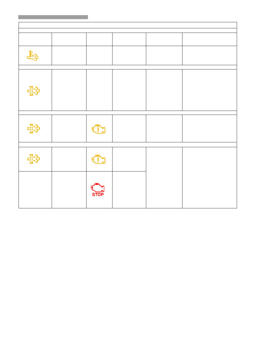
Funzionamento  degli indicatori

Durante  la rigenerazione  passiva  non si accende  nessun indicatore

Indicatore  di 
post-trattamento

Stato dell'indicatore 

di post-trattamento

Indicatore  di 

avviso

Stato 

dell'indicatore di 

avviso

Descrizione

Azione richiesta

Acceso fisso

-

-

La rigenerazione  

è attivata. 

L'indicatore rimane 

acceso durante la 

rigenerazione.

Nessuna

-

Acceso fisso

-

-

L'indicatore  fornisce 

un'indicazione  

generale del carico di 

fuliggine. Quando  il 

carico di fuliggine  è 

normale, l'indicatore 

è spento.

è necessaria  una rigenerazione.  

Nella modalità automatica, 

l'ECM  decide quando 

consentire  la rigenerazione  

attiva. Se l'indicatore  del DPF 

rimane acceso, è possibile una 

rigenerazione  manuale senza 

interruzioni.  La rigenerazione  

attiva senza  interruzioni 

ripristina  l'indicatore del DPF.

-

Acceso fisso

Lampeggiante

L'indicatore  indica 

che il carico 

di fuliggine è 

aumentato.
Si verifica una 

riduzione di potenza 

del motore.

è necessaria  una rigenerazione  

manuale. Eseguire  una 

rigenerazione  manuale oppure 

sarà necessaria una rigenerazione  

di servizio.

-

Acceso fisso

Lampeggiante

L'indicatore  di 

avviso lampeggiante  

e l'indicatore  di 

arresto rosso 

indicano  che 

il motore ha 

continuato 

a funzionare 

nonostante fosse 

necessaria  una 

rigenerazione.
Il motore  funziona

a potenza  

ridotta e deve 

essere arrestato 

immediatamente.

Quando il motore entra in 

modalità di arresto, contattare il 

distributore o il dealer Perkins.
Il concessionario o  il  

distributore dovrà  eseguire  

una rigenerazione  a livello 

di  manutenzione. Potrebbe  

essere necessario sostituire 

il DFP.

-

-

Acceso fisso

35

IT

EN

NL

Working of the indicators

During the passive regeneration none of the indicators lights up

Post-treatment 

indicator  

Status of post-

treatment indicator  

Warning 

indicator   

Status of 

warning 

indicator

Description

Action required

Steady light

-

-

The regeneration  

is activated. 

Theindicator 

remains ON during 

the regeneration.

None

-

Steadylight

-

-

The indicator  

provides a general  

indication of the 

amount of soot. 

When the amount of 

soot is normal, the 

indicatore is OFF.

A  regeneration is necessary.  

In automatic modee, theECM  

decides when regeneration 

must be  active. If the indicator  

of theDPF staysON, a manual 

regeneration is possiblewithout 

interruptions.  The active  

regeneration without  

interruptions resets the 

indicator of the DPF.

-

Steady light

Flashing light

The indicator  

indicates that the 

amount of soot has 

increased.
There is a reduction 

of the power of the 

engine.

A manu al regeneration  is 

necessary. Proceed with  a 

manual  regeneration or aservice 

regeneration  will be necessary.

-

Steady light

Flashing light

The warning 

indicator flashing  

and the red stop 

indicator indicate 

that the engine 

has continued to 

run although a 

regeneration  is 

necessary.
The engine  works at 

reduced power and 

must be stopped 

immediately.

When the eengine enters sto p 

mode, contact the distributor or 

the Perkins dealer.
The dealer or  the  distributor 

must carry out  a maintenance 

level regeneration. Itmaybe  

necessary to replace theDFP.

-

-

Steadylight

36

IT

EN

NL

Werking van de controlelampjes

Tijdens de passieve regeneratie gaat er geen enkel lampje branden 

Nabehandelings- 

lampje

Staat 
vanhetnabehandelingslampje  

Waarschuwingslampje  

Staatvan het 

waarschuwingslampje  

Beschrijving

Vereiste handeling

Ononderbroken aan

-

-

De regeneratie  

is geactiveerd. 

Het lampje blijft 

branden tijdens de 

regeneratie.

Geen

-

Ononderbroken aan

-

-

Het lampje  biedt een 

algemene aanwijzing  

van het roetgehalte. 

Als het roetgehalte 

normaal is , is het 

lampje uit.

Er is een regeneratie vereist.  In 

de automatische modus, beslist 

de ECM  wanneer de actieve 

regeneratie toe te laten . Als het 

lampje van het DPF blijft branden, 

is een handmatige regeneratie 

mogelijk zonder onderbrekingen.  

De actieve regeneratie zonder 

onderbrekingen  herstelt  het 

lampje van het DPF.

-

Ononderbroken aan

Knipperend

Het lampje geeft 

aan dat het 

roetgehalte is 

toegenomen.
De motor neemt af in 

vermogen.

Er is een handmatige regeneratie 

vereist. Voer een handmatige 

regeneratie uit anders is er een 

serviceregeneratie vereist.

-

Ononderbroken aan

Knipperend

Het knipperende 

waarschuwingslampje 

en het rode stoplampje 

geven aan dat de 

motor doorgewerkt 

heeft ondanks er een 

regeneratie vereist was. 
De motor draait met 

beperkt vermogen en 

moet onmiddellijk worden 

stopgezet.

Als de motor stopt, contact 

opnemen met de verkoper of de 

Perkins dealer .
De dealer of de 

verkoper moet dan een 

onderhoudsregeneratie 

verrichten. Het zou nodig 

kunnen zijn het DPF te 

vervangen..

-

-

Ononderbroken aan

37

IT

EN

NL

V - Pulsante livellamento automatico

     stabilizzatori (optional)

La macchina è dotata di un dispositivo

automatico di livellamento degli

stabilizzatori, rispetto al terreno, per poter 

livellare la macchina e quindi sollevare

il braccio all’altezza massima in tutta 

sicurezza e in completa stabilità.

Funzionamento dispositivo

Per livellare la macchina occorre: 

- selezionare i quattro stabilizzatori,

  “P1,P2,P3,P4”;

- sfilare o retrarre le travi degli stabilizzatori 

  in base alle proprie necessità;

- mantenere premuto il pulsante “V” 

  per attivare il dispositivo automatico di 

  livellamento degli  stabilizzatori;

- quando il dispositivo  di livellamento si 

   ferma la macchina  è livellata e stabilizzata,

  rilasciare il comando.

(Vedi immagine 3.10)

Z - Sospensione del braccio

La sospensione del braccio permette 

di ammortizzare le scosse del carrello 

elevatore su  terreno accidentato (esempio: 

movimentazione della paglia in un campo).
FUNZIONAMENTO

-  Posare le forche o l’accessorio al suolo 

e sollevare le ruote anteriori di pochi 

centimetri soltanto.

-  Premere l’interruttore “Z” in posizione “1”: 

  la spia si accende e indica che la

  sospensione del  braccio è attivata.

-  Premere l’interruttore “Z” in posizione “2”: 

 la spia si spegne e indica che la 

 sospensione del braccio è disattivata.

  La sospensione del braccio è attiva fino ad 

un’altezza di sollevamento di 3,00 m dall’asse 

d’articolazione della piastra rispetto al 

suolo con il braccio rientrato. Operando 

oltre quest’altezza o effettuando un altro 

movimento idraulico (inclinazione, telescopico, 

accessorio) la sospensione del braccio viene 

momentaneamente disattivata e la spia 

dell’interruttore 1 si spegne.

-  Quando il motore termico è spento, 

  la sospensione del braccio viene

  automaticamente disattivata.

  (Vedi immagine 3.10).

P

RESET

Mode

V

Z


3.10

V - Knop automatische nivellering 

stabilisatoren (optioneel)

De machine is voorzien van een automatisch 

nivelleringssysteem van de stabilisatoren 

ten opzichte van het terrein, om de machine 

te kunnen nivelleren en dus de arm veilig en 

stabiel tot de maximale hoogte te kunnen 

heffen.

Werking van het systeem

Voor de nivellering van de machine als volgt 

te werk gaan: 

- selecteer de vier stabilisatoren, 

“P1,P2,P3,P4”;

- de stangen van de stabilisatoren naar 

eigen behoefte uittrekken of intrekken;

- de knop “V” ingedrukt houden om het 

automatische nivelleringssysteem van de 

stabilisatoren te activeren;

- wanneer het automatische 

nivelleringssysteem stil staat is de machine 

genivelleerd en gestabiliseerd, de knop 

loslaten.

(Zie afbeelding 3.10)

Z - Vering van de arm

De vering van de arm dempt de schokken 

van de heftruck op onregelmatig terrein 

(voorbeeld: verplaatsen van stro op het 

land).
WERKING

-  Zet de vorken of het werktuig op de grond 

en til de voorwielen een paar centimeter 

van de grond.

-  Druk de schakelaar “Z” in de stand “1”: het 

controlelampje gaat aan en geeft aan dat 

de vering van de  arm actief is.

-  Druk de schakelaar “Z” in de stand “2”: het 

controlelampje gaat uit en geeft aan dat 

de vering van de arm uitgeschakeld is.

  De vering van de arm is actief tot aan een 

hefhoogte van 3,00 m van de gelede as 

van het bord ten opzichte van de grond 

met ingetrokken arm. Als u boven deze 

hoogte gaat of in het geval u een andere 

hydraulische beweging verricht (schuin zetten, 

uitschuiven, werktuig), zal de vering van de 

arm even worden uitgeschakeld en zal het 

controlelampje van schakelaar 1 doven.

-  Als de verbrandingsmotor uit is, wordt 

de vering van de arm automatisch 

gedeactiveerd.

  (Zie afbeelding 3.10).

2

1

P1

P2

P3

P4

V - Automatic stabilisers levelling button 

(optional)

The machine is provided with an automatic 

device for levelling the stabilisers, in relation 

to the ground, to be able to level the 

machine and therefore lift the boom to the 

maximum height in complete safety and 

stability.

Working of the device

To level the vehicle: 

- select the four stabilisers:  “P1, P2, P3, P4”;

- extend or retract the beams of the 

stabilisers as required;

- keep button “V" pressed to activate the 

stabilisers automatic levelling device;

- when the levelling device stops the 

vehicle is levelled and stabilised, release 

the button.

(See image 3.10)

Z - Boom suspension

The boom suspension makes it possible 

to absorb the shocks of the forklift truck 

on   uneven ground (for example: handling 

hay in a field).
OPERATION

-  Rest the forks or the attachment on the 

ground and raise the front wheels by only 

a few centimetres.

-  

Press switch “Z” in position “1”: the 

indicator lights up and indicates that the 

boom suspension  is activated.

-  

Press switch “Z” in position “2”: the 

indicator light switches off to indicate that 

the boom suspension is deactivated.

  The boom suspension is activated up to a 

height of 3.00m from the plate articulation 

axis in relation to the ground with the boom 

retracted. When working at this height or 

performing another hydralic movement 

(inclination, telescopic, accessory) the boom 

suspension is momentarily deactivated and the 

switch 1 indicator switches off.

-  

When the I.C. engine is switched off, 

the boom suspension is automatically 

deactivated.

  (See image 3.10)

38

IT

EN

NL

4 - QUADRo INTERRUTToRI  

A - Interruttore comando 2a e 3a 

     uscita optional (se installate). 

     (Vedi immagine 4)

B- Interruttore tergicristallo anteriore e 

    lavavetro

Interruttore a tre posizioni : 

disattivato (0); per tergicristallo (1); per 

lavavetro (2). 

Per disattivare il lavavetro é sufficiente 

rilasciare 

(Vedi immagine 4)

C - Interruttore comando optional 

     benna (se installata).

     (Vedi immagine 4)

D - Interruttore on-off  

     aria condizionata (optional).

     (Vedi immagine 4)

D.1 - Comando ventilazione 

         aria condizionata (optional)

Il comando ha 3 posizioni: 


1 - ventilazione minima

2 - ventilazione media

3 - ventilazione massima.

 (Vedi immagine 4)

4 - SCHAKELPANEEL  

A - Bedieningsschakelaar 2de en 3de 

uitgang optional (indien gemonteerd). 

(Zie afbeelding 4)

B - Schakelaar ruitenwisser voor en 

ruitensproeier

3-standenschakelaar: 

uit (0); ruitenwisser (1); ruitensproeier (2). 

Loslaten om de ruitensproeier uit te zetten. 

(Zie afbeelding 4)

C - Bedieningsschakelaar optional bak 

(indien gemonteerd).

(Zie afbeelding 4)

D - on-off schakelaar airconditioning 

(optioneel).

(Zie afbeelding 4)

D.1 - Bediening ventilatie 

airconditioning (optioneel)

De bediening heeft 3 standen: 


1 - minimum

2 - gemiddeld

3 - maximum.

(Zie afbeelding 4)

4

STOP

B

D

D1

A

C

0

1

2

4 - SWITCHBoARD  

A - optional oUTPUT 2a AND 3a 

CommAND SWITCH (if installed). 

(See image 4)

B- front windshield wiper and window 

washer switch

3-position switch: 

deactivated (0); for windshield wiper (1); for 

window washer (2). 

To deactivate the window washer, just 

release the switch. 

(See image 4)

C - mixer bucket command switch (if 

installed).

(See image 4)

D - Air conditioning on-off switch 

(optional).

(See image 4)

D.1 - Air conditioning ventilation control 

(optional)

The control has 3 positions: 


1 - minimum ventilation

2 - medium ventilation

3 - maximum ventilation.

(See image 4)

39

IT

EN

NL

STOP

5 - LIVELLA A BoLLA  

Situata a destra dell’operatore serve a 

controllare il livello della macchina su terreni 

sconnessi. In questi casi per ottenere il 

giusto livellamento della macchina rispetto 

al terreno si devono  usare gli stabilizzatori.


(Vedi immagine 5)

6 -  INTERRUTToRE LUCI  D’EmERGENZA

Premendo questo interruttore si  attivano 

contemporaneamente tutti gli indicatori di 

direzione. Per disattivare premere di nuovo 

l’ interruttore.

(Vedi immagine 6)

7 -  PULSANTE “ARRESTo D’EmERGENZA”

In caso d’emergenza, premere il 

pulsante rosso a fungo, per arrestare il 

motore termico della macchina.
Per ripristinare il motore e i movimenti della 

macchina ruotare il 

pulsante rosso in senso orario.

(Vedi immagine 7)

5 - WATERPAS  

Aan de rechterkant van de bestuurder, 

dient om de nivellering van de machine 

op onregelmatig terrein te controleren. In 

dit geval moeten de stabilisatoren gebruikt 

worden om een goede nivellering van de 

heftruck ten opzichte van het terrein te 

verkrijgen.


(Zie afbeelding 5)

6 - SCHAKELAAR PANIEKLICHTEN

Door deze schakelaar in te drukken gaan 

alle richtingaanwijzers tegelijk aan. Om 

ze uit te zetten deze schakelaar nogmaals 

indrukken.

(Zie afbeelding 6)

7 - “NooDSToP” KNoP

In geval van nood, de rode 

paddelstoelvormige knop indrukken om de 

verbrandingsmotor van de machine uit te 

zetten.
Om de motor en de bewegingen van de 

machine weer te herstellen de rode knop in 

de richting van de klok draaien.

(Zie afbeelding 7)

7

6

5

°C

hours

7

6

5

5 - SPIRIT LEVEL  

Situated to the RH of the operator, it is used 

for checking the vehicle level on uneven 

ground. In these cases, the stabilisers must 

be used to obtain correct leveling of the 

vehicle with respect to the ground.


(See 

image 5)

6 – EmERGENCY LIGHTS SWITCH

Pressing this switch will activate all the 

direction indicators simultaneously. To 

deactivate the indicators, press the switch 

again.

(See image 6)

7 – "EmERGENCY SToP" PUSHBUTToN

In case of emergency, press the red 

mushroom-shaped button to stop the 

vehicle’s I.C. engine.
To restore the engine and vehicle 

movements, turn the red pushbutton 

clockwise.

(See image 7)

40

IT

EN

NL

°C

hours

8 - PANNELLo DI CoNTRoLLo e 

      LImITAToRE DI CARICo (mSS) 

Il pannello di controllo, costituito da un 

Display  7”  a colori, 10 tasti programmabili 

+ 5 tasti funzione , visualizza e informa 

l’operatore del  funzionamento della 

macchina in tutte le  sue fasi di lavoro

.


(Vedi immagine 8)

Nr.5 sono le modalità di controllo

memorizzate all’interno del pannello 


che  si selezionano premendo i 

tasti


f1,f2,f3,f4,f5

 :


8 - BEDIENINGSPANEEL en 

BELASTINGBEGRENZER (mSS)  

Het controlepaneel, bestaande uit een 

7” kleurendisplay, 10 programmeerbare 

toetsen + 5 functietoetsen, toont en 

informeert de bestuurder over de werking 

van de machine tijdens al zijn werkfases.

.


(Zie afbeelding 8)

Er zijn 5 controlemodaliteiten in het 

geheugen van het paneel opgeslagen 

die u kunt selecteren door de 

toetsen


f1,f2,f3,f4,f5

 in te drukken:

8

8 - CoNTRoL PANEL AND LoAD LImITER (mSS) 

The control panel, consisting of a 7”  colour 

display, 10 programmable keys + 5 function 

keys, displays and informs the operator of 

all the steps of the working of the machine

.


(See image 8)

Five control modes are saved in memory 

in the panel and these can be selected by 

pressing the

keys


f1, f2, f3, f4, f5

 :

41

IT

EN

NL

f1 - CoNTRoLLo moDALITÀ GUIDA

.


   (Vedi immagine F1)

f2 -  CoNTRoLLo moDALITÀ 
          LImITAToRE DI CARICo 

   (Vedi immagine F2)

f3 - CoNTRoLLo moDALITÀ LImITI 
         GEomETRICI


(Vedi immagine F3)

f4 - CoNTRoLLo VELoCITA mASSImA 
         moVImENTI IDRAULICI


(Vedi immagine F4)

f5 - CoNTRoLLo moDALITÀ 
          DIAGNoSTICA mACCHINA.


(Vedi immagine F5)


f1 - BESTURINGSmoDALITEIT

.


(Zie afbeelding F1)

f2 - moDALITEIT 
BELASTINGBEGRENZER  

(Zie afbeelding F2)

f3 - moDALITEIT GEomETRISCHE 
LImIETEN

(Zie afbeelding F3)

f4 - moDALITEIT mAXImUmSNELHEID 
HYDRAULISCHE BEWEGINGEN


(Zie afbeelding F4)

f5 - moDALITEIT mACHINEDEAGNoSE.


(Zie afbeelding F5)

f1

f2

f3

f3

f5

f4

mRT 1840 ST3B (360°)

mRT 1440-1640-1840 ST3B (400°)

f1 - DRIVE moDE CoNTRoL

.


(See image F1)

f2 -  LoAD LImITER moDE CoNTRoL 

(See image F2)

f3 - GEomETRIC LImITS moDE 
CoNTRoL

(See image F3)

f4 - HYDRAULIC moVEmENTS 
mAXImUm SPEED


(See image F4)

f5 - mACHINE DIAGNoSTIC moDE 
CoNTRoL.


(See image F5)


Content      ..     8      9      10      11     ..