Yaskawa iQpump Micro AC Drive Compact Intelligent Pump Controller. User Manual (2014) - page 10
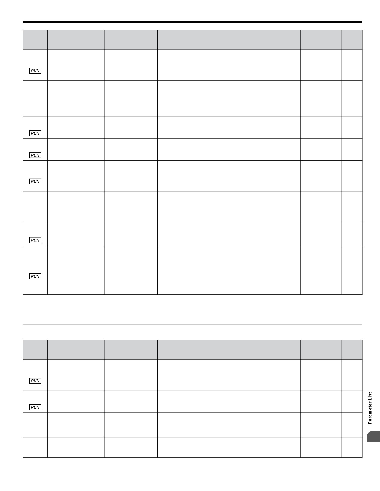
B.12 P: Pump Parameters
No.
(Addr.
Name
LCD Display
Description
Values
Page
Hex)
Selects the alarm message that will be displayed when a Low
Low City Alarm Txt
P4-24
City Pressure condition is detected.
0: Low Cty Pressure
Default: 0
(0D11)
Low City Alarm Text
0: Low city pressure
234
1: Low Suction Pres
Range: 0 to 2
1: Low suction pressure
2: Low Watr in Tank
2: Low water in tank
Selects the type of pressure switch connected to the “Remote
Drive Disable” digital input (H1-0o = 95).
Rem Drv Dis Sel
P4-25
Remote Drive Disable
0: Normally open (closed indicates the Remote Drive Disable
Default: 1
0: Normally Open
234
(0D12)
Selection
condition)
Range: 0, 1
1: Normally Closed
1: Normally closed (open indicates the Remote Drive Disable
condition)
P4-26
Sets the amount of time a Remote Drive Disable condition must
Default: 0 s
(0D13)
Remote Drive Disable
be present before the drive will stop.
Drv Dis On-Delay
Min.: 0
234
On-Delay
Max.: 1000
P4-27
Sets the amount of time a Remote Drive Disable condition must
Default: 0 s
Remote Drive Disable
(0D14)
Drv Dis OffDelay
be absent before the drive will run.
Min.: 0
234
Off-Delay
Max.: 1000
Selects which text is displayed when Lube Pump is active. Also
P4-29
Lube Pump Text
changes the text for the Lube Pump Digital Output selection
(0D16)
Lube Pump Message
Default: 0
0: Lube Pump
(H2-oo = 8B)
234
Text
Range: 0, 1
1: DigitalOut Delay
0: Lube Pump
1: Digital Out Delay
When enabled, the Lube Pump digital output stays activated
Lube Pump DurRun
after the timer expires and the drive starts to run normally. The
P4-30
Lube Pump Active
Default: 0
0: Disabled
output is deactivated only when the drive stops, faults, or sleeps.
234
(0D17)
During Run
Range: 0, 1
1: Active DuringRun
0: Disabled
1: Active During Run
Sets the amount of time to delay the drive output and to energize
P4-31
Default: 0.0 s
Lube Pump / Digital
the digital output (H2-oo = 8B) before the drive is allowed to
(0D18)
Lube Pump Time
Min.: 0.0
235
Output Delay Timer
run.
Max.: 300.0
Setting this parameter to 0.0 disables the function.
For normal PID operation during Pre-charge 2, if the PID
Feedback signal rises above the P4-32 level, Pre-charge 2 is
P4-32
cancelled and the drive resumes normal operation.
Default: 0.0 PSI
For inverse PID operation and during Pre-charge 2, if the PID
<1>
(0D19)
Pre-charge Level 2
PreCharge Level2
235
Feedback signal goes below the P4-32 level, Pre-charge 2 is
Min.: 0.0
cancelled and the drive resumes normal operation.
Max.: 6000.0
When set to zero, Pre-charge 2 still runs when P4-07 is set, but
uses P4-01 to determine if normal operation should resume.
<1> Unit is determined by P1-02, System Units; scaling is determined by P1-03, Feedback Device Scaling; resolution is determined by b5-39, PID
System Units Display Digits.
<2> Unit text is set by P1-18, Prime Loss Detection Method.
u P5: Pump HAND Mode
No.
(Addr.
Name
LCD Display
Description
Values
Page
Hex)
Sets the HAND Mode reference.
P5-01
Hand Mode Ref.
0: Analog input
(0D2C)
HAND Mode Ref
Default: 1
0: Analog Input
235
Source
Note:
Analog input is defaulted to input A1 (0-10 V).
Range: 0, 1
1: Hand Ref 1 (OPR)
1: P5-02 (HAND reference)
P5-02
Sets the frequency reference used when HAND Mode is active
Default: 40.0 Hz
(0D2D)
HAND Reference 1
HAND Reference 1
and P5-01 is set to 1.
Min.: 0
235
Max.: [E1-04]
Selects whether the drive will permit switching between HAND
HAND/AUTO @ Run
P5-03
HAND/AUTO During
and AUTO Modes while running.
Default: 0
0: Disabled
235
(0D2E)
Run Selection
0: Disabled
Range: 0, 1
1: Enabled
1: Enabled
B
Oper HAND Key
Enables and disables the HAND key on the HOA keypad.
P5-04
HAND Key Function
Default: 1
0: Disabled
0: Disabled
236
(0D2F)
Selection
Range: 0, 1
1: Enabled
1: Enabled
361
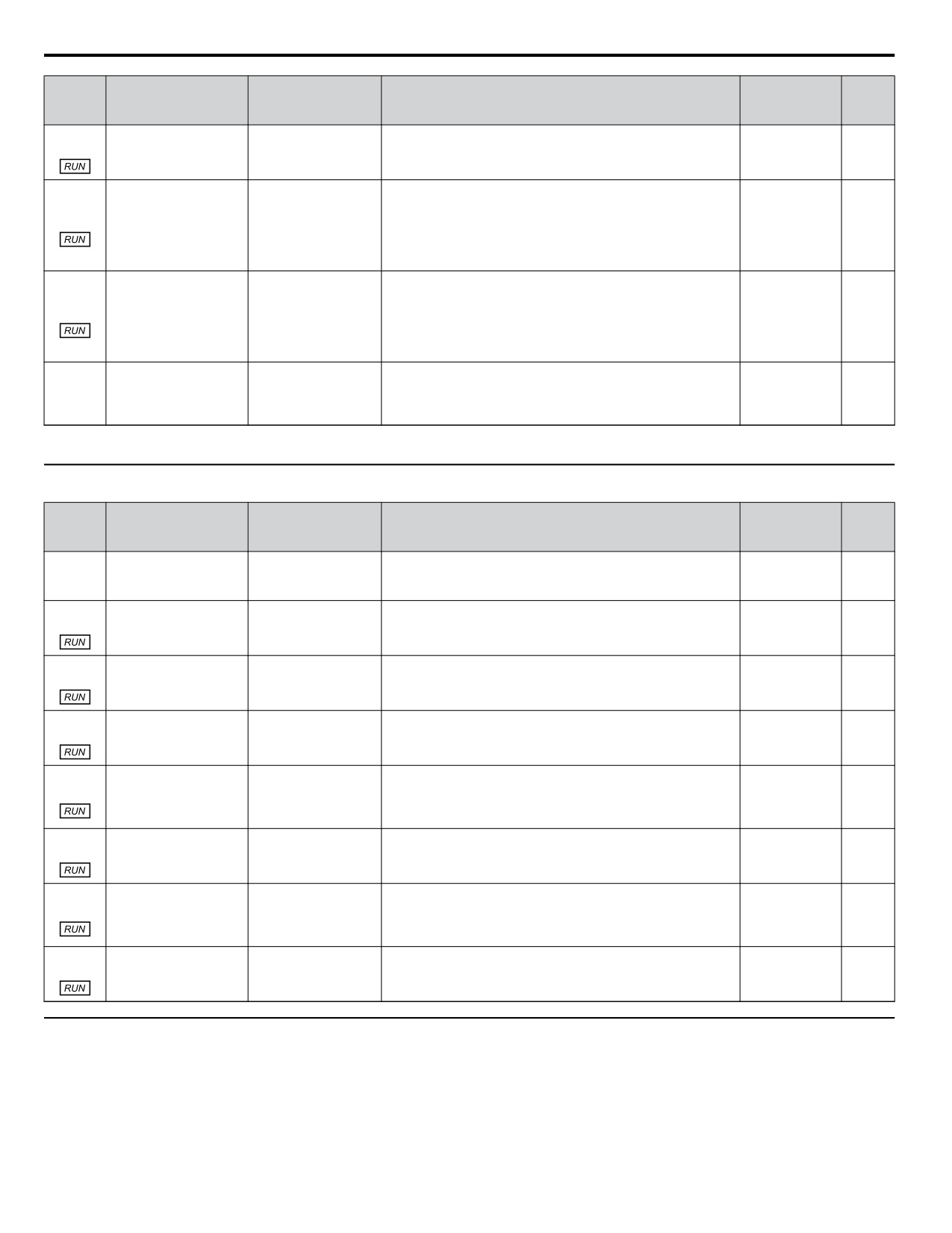
B.12 P: Pump Parameters
No.
(Addr.
Name
LCD Display
Description
Values
Page
Hex)
P5-05
Sets the frequency reference used when HAND Mode 2 is
Default: 0.0 Hz
(0D30)
HAND Reference 2
HAND Reference 2
active.
Min.: 0.0
236
Max.: [E1-04]
Detects loss of prime in the pump when in HAND Mode.
P5-06
When the measured quantity determined by P1-18 drops below
Default: 0.0 A
HAND Ref. 1 Loss of
this level for the time set in P1-20 and the output frequency is
<1>
(0D31)
HandRef1 LOP Lvl
236
Prime Level
at the level set in P5-02, a “Loss of Prime” condition occurs.
Min.: 0.0
The drive responds to the “Loss of Prime” condition depending
Max.: 1000.0
on the setting of P1-22, Loss of Prime Selection.
Detects loss of prime in the pump when in HAND Mode 2.
When the measured quantity determined by P1-18 drops below
Default: 0.0 A
P5-07
HAND Ref. 2 Loss of
this level for the time set in P1-20 and the output frequency is
<1>
(0D32)
HandRef2 LOP Lvl
236
Prime Level
at the level set in P5-05, a “Loss of Prime” condition occurs.
Min.: 0.0
The drive responds to the “Loss of Prime” condition depending
Max.: 1000.0
on the setting of P1-22, Loss of Prime Selection.
Selects whether parameters P5-02 and P5-05 are changed via
HAND References Set
HAND MOP Sel
P5-09
MOP from the home screen.
Default: 0
via Motor Operated Pot
0: Disabled
236
(0D34)
0: Disabled
Range: 0, 1
Selection
1: Enabled
1: Enabled
<1> Unit text is set by P1-18, Prime Loss Detection Method.
u P7: Anti-Jam
No.
(Addr.
Name
LCD Display
Description
Values
Page
Hex)
Anti-Jam Sel
Enables and disables the anti-jam function.
P7-01
Anti-Jam Operation
Default: 0
0: Disabled
0: Disabled
237
(0D90)
Selection
Range: 0, 1
1: Enabled
1: Enabled
P7-02
Sets the maximum number of cycles that will be attempted
Default: 1
(0D91)
Anti-Jam Cycle Count
AJ Cycle Count
before triggering and Anti-Jam fault.
Min.: 1
237
Max.: 100
P7-03
Sets the current level at start that will trigger the anti-jam
Default: 120%
Anti-Jam Detection
(0D92)
AJ Det I @Start
function.
Min.: 50
237
Current Level
Set as a percentage of the motor rated current.
Max.: 200
P7-04
Sets the length of time that current must rise above the level set
Default: 0.3 s
(0D93)
Anti-Jam Detection
in P7-03 to trigger the anti-jam function.
AJ Det Tm@Start
Min.: 0.1
237
Time at Start
Max.: 2.0
P7-05
Sets the current level during run that will trigger the anti-jam
Default: 0%
(0D94)
Anti-Jam During Run
function.
AJ Det I @Run
Min.: 0
237
Current
Set as a percentage of motor rated current.
Max.: 200
Setting this parameter to 0 will disable anti-jam during run.
P7-06
Sets the length of time that the current must rise above the level
Default: 0.3 s
(0D95)
Anti-Jam During Run
AJ Det Tm @Run
set in P7-05 to trigger the anti-jam function.
Min.: 0.1
237
Time
Restricted to simplex only.
Max.: 2.0
Sets the maximum speed allowed when the anti-jam function is
Default: 25.00
P7-07
Anti-Jam Frequency
active.
Hz
(0D96)
AJ Freq Ref
237
Reference
Min.: 0.00
Max.: 400.00
P7-08
Sets the length of time that the current must fall below the level
Default: 2.0 s
(0D98)
Anti-Jam Release Time
AJ Release Time
set in P7-03 to resume normal operation.
Min.: 0.5
237
Max.: 10.0
u P9: Network Options
Parameters in this group are functional only when P1-01, Pump Mode, is set to 3 (MEMOBUS network).
362
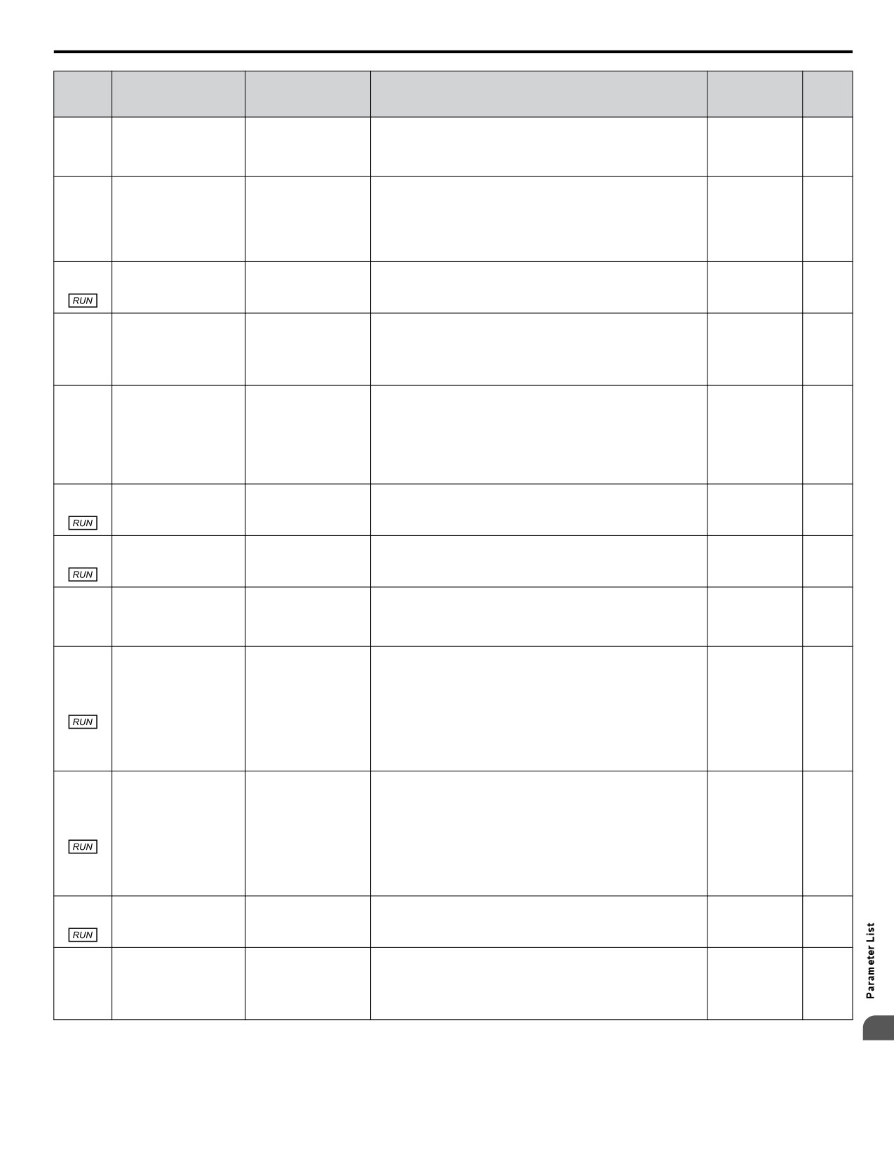
B.12 P: Pump Parameters
No.
(Addr.
Name
LCD Display
Description
Values
Page
Hex)
Lead Drive Sel
Specifies how the next lead drive is selected.
P9-01
0: Next Available
0: Next available
Default: 1
Lead Drive Selection
238
(0DF4)
1: Lowest Runtime
1: Lowest runtime
Range: 0 to 2
2: Stop History
2: Stop history
Defines which signal to use for PID feedback when P1-01, Pump
Feedback Source
Mode, is set to 3 (MEMOBUS network).
0: Analog only
P9-02
0: Analog only
Default: 0
Feedback Source
1: Ana->Net, No Alrm
238
(0DF5)
1: Ana->Net, No Alrm
Range: 0 to 3
2: Ana->Net, Alarm
2: Ana->Net, Alarm
3: Network only
3: Network only
P9-03
Specifies the time for a drive to request alternation.
Default: 24 H
(0DF6)
Alternation Time
Alternation Time
Setting this parameter to 0 disables the function.
Min.: 0
239
Max.: 1000
Alternation Mode
Determines how alternation is performed.
0: FIFO Auto
0: FIFO auto
P9-04
Default: 0
Alternation Mode
1: FIFO Forced
1: FIFO forced
239
(0DF7)
Range: 0 to 3
2: LIFO
2: LIFO
3: FIFO @ Sleep
3: FIFO @sleep
Determines the functionality of the lag drives.
0: Fixed speed. The drive runs at the P9-06 setting after the time
Lag Drive Mode
set in P9-07 expires.
P9-05
0: Fixed Speed
Default: 0
Lag Drive Mode
2: Turn off. The drive stops running when it switches to a lag
239
(0DF8)
2: Turn Off
Range: 0, 2, 3
drive after the time set in P9-07 expires.
3: Follow Lead Spd
3: Follow Lead Speed. The drive will follow the speed of the
current lead drive, applying P9-30 gain and P9-31 bias.
P9-06
Sets the speed at which the drive will run when the drive changes
Default: 55.0 Hz
(0DF9)
Lag Fixed Speed
Lag Fixed Speed
from a lead to a lag and the time set in P9-07 has expired.
Min.: 0.0
239
Max.: 400.0
P9-07
Specifies how long speed is latched before performing the
Default: 5 s
(0DFA)
Lag Fixed Speed Delay
Lag Fix Spd Dly
function specified in P9-05 when the drive changes from a lead
Min.: 0
239
to a lag.
Max.: 1000
Add Pump Mode
Selects the detection method for staging a new pump.
P9-08
0: Output Frequency
0: Output frequency
Default: 2
Add Pump Mode
240
(0DFB)
1: Feedback
1: Feedback
Range: 0 to 2
2: Feedback + Fout
2: Feedback + Fout
When P9-08 is set to 0, this parameter sets the level above which
the output frequency needs to rise for the time set in P9-11 before
the lead drive will send a request for a new lead drive via the
P9-09
iQPump MEMOBUS network.
Default: 59.5 Hz
(0DFC)
Add Frequency Level
Add Freq Lvl
When P9-08 is set to 2 and the delta feedback (setpoint minus
Min.: 0.0
240
feedback) has exceeded the level set in P9-10 for the time set in
Max.: 400.0
P9-11, this parameter sets the level above which the output
frequency needs to rise before the lead drive will send a request
for a new lead drive via the iQPump MEMOBUS network.
When P9-08 is set to 1, this parameter sets the level above which
the delta feedback (setpoint minus feedback) must rise for the
time set in P9-11 before the lead drive will send a request for a
P9-10
Default: 4.0 PSI
new lead drive via the iQPump MEMOBUS network.
<1>
(0DFD)
Add Delta Level
Add Delta Lvl
When P9-08 is set to 2 and the output frequency has exceeded
240
Min.: 0.0
the level set in P9-09 for the time set in P9-11, this parameter
Max.: 6000.0
sets the level above which the delta feedback (setpoint minus
feedback) needs to rise before the lead drive will send a request
for a new lead drive via the iQPump MEMOBUS network.
P9-11
Sets the delay time before a new lead drive is added to the
Default: 10 s
(0DFE)
Add Delay Time
Add Dly Time
system.
Min.: 0
240
Max.: 3600
Sets the detection method for de-staging to the previous lead
Remove Pump Mode
pump.
P9-12
0: Output Frequency
Default: 0
Remove Pump Mode
0: Output frequency
240
(0DFF)
1: Feedback
Range: 0 to 2
1: Feedback
2: Feedback + Fout
2: Feedback + Fout
B
363
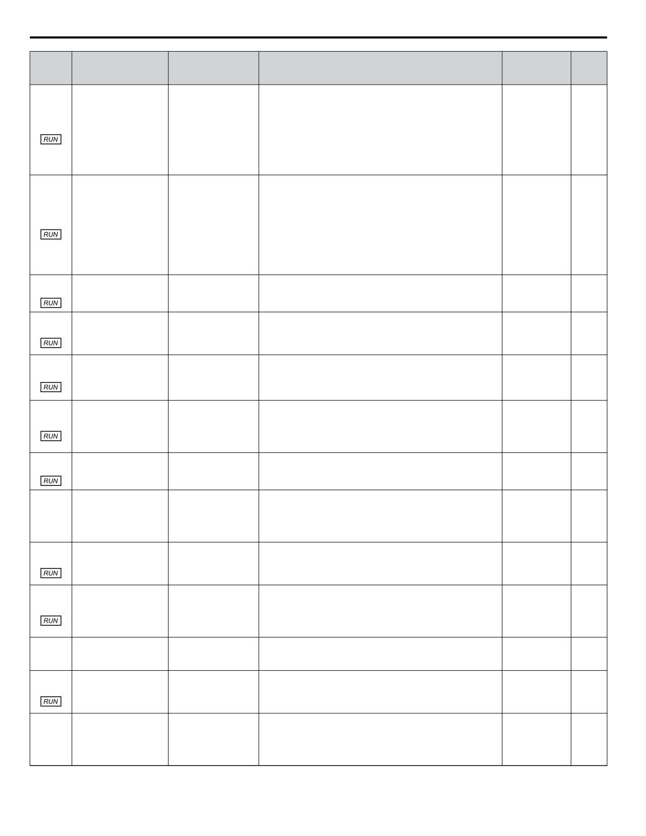
B.12 P: Pump Parameters
No.
(Addr.
Name
LCD Display
Description
Values
Page
Hex)
When P9-12 is set to 0, this parameter sets the level below which
the output frequency must fall for the time set in P9-15 before
the lead drive will send a request to be removed from the system
P9-13
via the iQPump MEMOBUS network.
Default: 40.0 Hz
Remove Frequency
(0E00)
Remove Freq Lvl
When P9-12 is set to 2 and the delta feedback (feedback minus
Min.: 0.0
240
Level
setpoint) has exceeded the level set in P9-14 for the time set in
Max.: 400.0
P9-15, this parameter sets the level below which the output
frequency must fall before the lead drive will request to be
removed from the system via the iQPump MEMOBUS network.
When P9-12 is set to 1, this parameter sets the level above which
the delta feedback (feedback minus setpoint) must rise for the
time set in P9-15 before the lead drive will request to be removed
from the system via the iQPump MEMOBUS network.
Default: 0.0 PSI
P9-14
When P9-12 is set to 2 and the output frequency has exceeded
<1>
(0E01)
Remove Delta Level
Remove Delta Lvl
243
the level set in P9-13 for the time set in P9-15, this parameter
Min.: 0.0
sets the level above which the delta feedback (feedback minus
Max.: 6000.0
setpoint) frequency must rise before the lead drive will request
to be removed from the system via the iQPump MEMOBUS
network.
P9-15
Sets the delay time before the lead drive is removed from the
Default: 10 s
(0E02)
Remove Delay Time
Remove Dly Time
system.
Min.: 0
241
Max.: 3600
P9-16
Sets the time used to stabilize the system when a pump is staged
Default: 3 s
(0E03)
or de-staged.
Stabilization Time
Stabilize Time
Min.: 0
241
Lead/lag control and pump protection are suspended during this
Max.: 3600
time.
Sets the value by which the system setpoint is incremented
Default: 0.0 PSI
P9-17
depending on the number of pumps that are running.
<1>
(0E04)
Setpoint Modifier
Set-pt Modifier
241
Pump 1: Setpoint
Min.: -999.9
Pump 2: Setpoint + ((X-1) (P9-17))
Max.: 999.9
Sets the feedback level that will trigger a quick de-stage. Set as
P9-18
a percentage of the P1-11 value.
Default: 97.0%
(0E05)
High Feedback Quick
High FB De-stage
The quick de-stage ignores parameters P9-12 to P9-15 and uses
Min.: 0.0
241
De-Stage
an internal 2 second delay.
Max.: 100.0
Setting this parameter to 0.0 disables the feature.
P9-19
Alternation Unit
Sets the units used in P9-03.
Default: 0
(0E06)
Alternation Unit
0: Hours (H)
0: Hours (H)
241
Range: 0, 1
1: Minutes (min)
1: Minutes (min)
Allow Net Run
Specifies when a network Run command is allowed.
0: Always
0: Always
P9-20
Default: 0
Allow Network Run
1: First/Altrnation
1: First/alternation
241
(0E07)
Range: 0 to 3
2: First Only
2: First only
3: Alternation Only
3: Alternation only
P9-21
Sets the lead drive selection priority overriding the P9-01
Default: 8
(0E08)
selection. Lower value = Higher priority.
Run Priority
Run Priority
Min.: 1
242
If multiple drives have the lowest P9-21 value, then P9-01
Max.: 16
determines which drive becomes the lead.
Sets the number of times that the iQPump MEMOBUS network
P9-22
will allow automatic restarts of system faults.
Default: 5
(0E09)
System Fault Retry
System Flt Retry
The drive uses L5-04, Fault Reset Interval Time, to determine
Min.: 0
242
when to attempt a system fault restart.
Max.: 10
Set this parameter to the same value for all drives on the network.
Sets the maximum number of pumps that can run on the system.
Default: 4
P9-23
Maximum Number of
MaxPumps Running
Min.: 1
242
(0E0A)
Running Pumps
Max.: 4
Sets the length of time for which the lead drive will be in Sleep
P9-24
Default: 0 s
Mode before this drive will request a swap when there is another
(0E0B)
Lead Swap at Sleep
Lead Swap @Sleep
Min.: 0
242
drive available with a lower P9-21 setting.
Max.: 7200
Setting this parameter to 0 will disable the function.
Sets the highest possible node address in the MEMOBUS
network.
Default: 4
P9-25
Highest Node Address
Highest Node Adr
For optimal network performance, set the serial communication
Min.: 2
243
(0E0C)
address H5-01 beginning with 01h consecutively up to the last
Max.: 4
drive and then set this parameter to that H5-01 address.
364
B.12 P: Pump Parameters
No.
(Addr.
Name
LCD Display
Description
Values
Page
Hex)
Sets the minimum amount of time that the slave drives will wait
Default: 4.0 s
P9-26
Master Time-out
Master Time-out
for a message from the master before performing the action set
Min.: 1.0
243
(0E0D)
in P9-27.
Max.: 10.0
Determines the drive response when no messages are received
from the master for the time set in P9-26.
Network Recovery
0: Automatic. The drive will attempt to assume master
0: Automatic
functionality.
P9-27
Default: 0
Network Recovery
1: Slave/Resume
1: Slave/Resume. The drive will continue running when the
243
(0E0E)
Range: 0 to 3
2: Slave/Stop
master is lost and will wait for a master to come online.
3: Fault MSL
2: Slave/Stop. The drive will stop running when the master is
lost and will wait for a master to come online.
3: Fault MSL. Fault the drive with an MSL (Master Lost).
Sets the amount of time that the slave drives will wait for a
Default: 2.0 s
P9-28
NETSCAN Alarm Time
NETSCAN AlrmTime
message from the master before displaying a NETSCAN alarm.
Min.: 1.0
243
(0E0F)
Max.: 10.0
P9-29
Sets the amount of time that the network will wait before
Default: 2.0 s
(0E10)
Net Start Delay
Net Start Delay
selecting and starting the lead drive after the first drive on the
Min.: 0.0
243
network has been put on AUTO Mode.
Max.: 60.0
P9-30
Sets the gain to be applied to the speed of the current lead drive
Default: 100.0%
(0E11)
Lag Drive Speed
when P9-05 is set to 3. The bias to be applied is set in P9-31.
Lag Followr Gain
Min.: 0.0
243
Follower Gain
Max.: 300.0
P9-31
Sets the bias to be applied to the speed of the current lead drive
Default: 0.00 Hz
(0E12)
Lag Drive Speed
when P9-05 is set to 3. The gain to be applied is set in P9-30.
Lag Followr Bias
Min.: -60.0
243
Follower Bias
Max.: 60.0
P9-32
Sets the deceleration time when the P9-33 timer is running and
Default: 60.0 s
Lag Follower
(0E13)
Lag Followr Dcel
the drive is running as Lag Drive Speed Follower (P9-05 is set
Min.: 0.0
244
Deceleration Time
to 3).
Max.: 1000.0
Sets the time during which the deceleration time set in P9-32 is
P9-33
Lag Follower
Default: 0.0 s
effective. The drive will use the standard deceleration rate when
(0E14)
Deceleration Time
Lag Followr Dtim
Min.: 0.0
244
it expires.
Active Time
Max.: 3600.0
Setting this parameter to 0.0 disables the function.
P9-34
Sets the low feedback level that will trigger a quick de-stage.
Default: 0.0 PSI
Low Feedback Quick
The quick de-stage ignores parameters P9-12 and P9-15 and
<1>
(0E15)
Low FB De-stage
244
De-Stage
only uses an internal 2 second delay.
Min.: 0.0
Setting this parameter to 0.0 disables the function.
Max.: 6000.0
Determines the communication compatibility for the iQPump
Network Comp Sel
MEMOBUS network.
P9-99
Network Compatibility
0: A-Ver: 30034
Default: 2
0: A-Ver: 30034
244
(0E56)
Selection
1: B-Ver: 30035/36
Range: 0 to 2
1: B-Ver: 30035/36
2: iQ SmartNetwork
2: iQ SmartNetwork
<1> Unit is determined by P1-02, System Units; scaling is determined by P1-03, Feedback Device Scaling; resolution is determined by b5-39, PID
System Units Display Digits.
B
365
B.13 Q: PID Controller Parameters
B.13 Q: PID Controller Parameters
u Q1: Preset Setpoint
No.
(Addr.
Name
LCD Display
Description
Values
Page
Hex)
Sets the PID Setpoint when b1-01 is set to 0.
Default: 0.0
Q1-01
Min.: 0.0
(0E58)
PID Controller Setpoint 1
Setpoint 1
245
Max.: 6000.0
<1>
Sets the PID Setpoint when the “Multi Setpoint 1” or
Default: 0.0
Q1-02
"Alternate Multi Setpoint 1" multi-function digital input is
Min.: 0.0
(0E59)
PID Controller Setpoint 2
Setpoint 2
245
closed.
Max.: 6000.0
<1>
Sets the PID Setpoint when the “Multi Setpoint 2” or
Default: 0.0
Q1-03
"Alternate Multi Setpoint 2" digital input is closed.
Min.: 0.0
(0E5A)
PID Controller Setpoint 3
Setpoint 3
245
Max.: 6000.0
<1>
Sets the PID Setpoint when the “Multi Setpoint 1” and “Multi
Default: 0.0
Q1-04
Setpoint 2” or “Alternate Multi Setpoint 3” multi-function
Min.: 0.0
(0E5B)
PID Controller Setpoint 4
Setpoint 4
245
digital inputs are closed.
Max.: 6000.0
<1>
Selects whether parameters Q1-01 to Q1-04 are changed via
Setpoint MOP
Q1-09
PID Setpoint Set via Motor
MOP from the home screen.
Default: 0
0: Disabled
245
(0E60)
Operated Pot
0: Disabled
Range: 0, 1
1: Enabled
1: Enabled
<1> Unit is determined by P1-02, System Units; scaling is determined by P1-03, Feedback Device Scaling; resolution is determined by b5-39, PID
System Units Display Digits.
u Q3: Output Current Limit
No.
(Addr.
Name
LCD Display
Description
Values
Page
Hex)
Current Lim Sel
Enables and disables the output current regulator.
Q3-01
Output Current Limit
Default: 0
0: Disabled
0: Disabled
245
(0EBC)
Select
Range: 0, 1
1: Enabled
1: Enabled
Sets the current limit. Value is internally limited to 300% of the
Default: 0.0 A
Q3-02
Current Limit
Current Limit
drive rated current.
Min.: 0.0
245
(0EBD)
Max.: 1000.0
Ripple Reg Sel
Enables and disables the single phase ripple regulator.
Q3-10
Ripple Regulator
0: Disabled
0: Disabled
Default: 1
245
(0EC5)
Selection
1: Enabled
1: Enabled
Range: 0 to 2
2: Enabled(Reactor)
2: Enabled w/ Line Reactor
Default: 95.0%
Q3-11
Ripple Regulator
Set as a percentage of the maximum amount of ripple allowed
Ripple Reg S.P.
Min.: 0.0
245
(0EC6)
Setpoint
before triggering an input phase loss fault.
Max.: 200.0
366
B.14 S: Special Application
B.14 S: Special Application
u S6: Protection
No.
(Addr.
Name
LCD Display
Description
Values
Page
Hex)
Sets the speed command used in emergency override mode
Default: 0.00 Hz
S6-01
Emergency Override
E Override Speed
when S6-02 = 0.
Min.: 0.00
246
(3236)
Speed
Max.: 240.00
E OverrideRefSel
Selects the emergency override speed source.
S6-02
Emergency Override
Default: 0
0: Use S6-01 Ref
0: Use S6-01 Reference
246
(3237)
Reference Selection
Range: 0, 1
1: Use Freq Ref
1: Use Frequency Reference
B
367
B.15 T: Motor Tuning
B.15 T: Motor Tuning
Enter data into the following parameters to tune the motor and drive for optimal performance
u T1: Induction Motor Auto-Tuning
No.
(Addr.
Name
LCD Display
Description
Values
Page
Hex)
T1-01
Auto-Tuning Mode
Tuning Mode Sel
2: Stationary Auto-Tuning for Line-to-Line Resistance
Default: 2
102
(0701)
Selection
2: Term Resistance
Range: 2
Sets the motor rated power as specified on the motor nameplate.
Default: <1>
T1-02
Note:
Use the following formula to convert horsepower
Min.: 0.03 kW
Motor Rated Power
Mtr Rated Power
103
(0702)
into kilowatts:
Max.: 650.00
1HP = 0.746 kW.
kW
Sets the motor rated current as specified on the motor
Default: <1>
nameplate.
Min.: 10% of
drive rated
T1-04
Motor Rated Current
Rated Current
current
103
(0704)
Max.: 200% of
drive rated
current
<1> Default setting is dependent on parameter o2-04, Drive Model Selection.
368
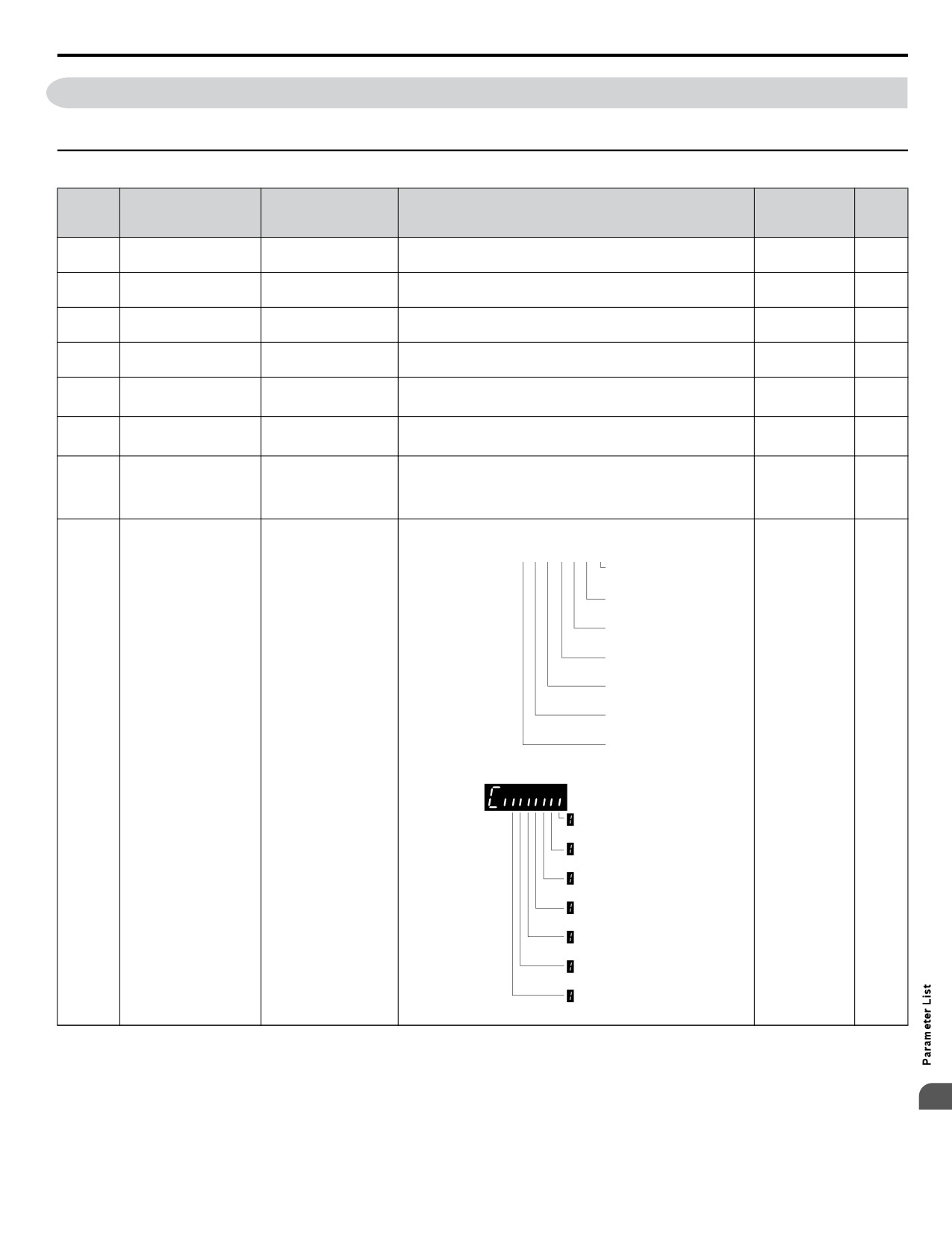
B.16 U: Monitors
B.16 U: Monitors
Monitor parameters allow the user to view drive status, fault information, and other information about drive operation.
u U1: Operation Status Monitors
No.
Analog
(Addr.
Name
LCD Display
Description
Unit
Output Level
Hex)
U1-01
Monitors the frequency reference. Display units are determined
10 V: Max
Frequency Reference
Frequency Ref
0.01 Hz
(0040)
by o1-03.
frequency
U1-02
Displays the output frequency. Display units are determined by
10 V: Max
Output Frequency
Output Freq
0.01 Hz
(0041)
o1-03.
frequency
U1-03
Displays the output current.
10 V: Drive
<2>
Output Current
Output Current
<1>
(0042)
rated current
U1-04
0: V/f Control
No signal output
Control Method
Control Method
-
(0043)
available
U1-06
Output Voltage
Displays the output voltage.
10 V: 200 Vrms
Output Voltage
0.1 Vac
(0045)
Reference
<3>
U1-07
Displays the DC bus voltage.
10 V: 400 V
DC Bus Voltage
DC Bus Voltage
<3>
1 Vdc
(0046)
Displays the output power (this value is calculated internally).
10 V: Drive
U1-08
capacity
<4>
Output Power
Output kWatts
(0047)
(motor capacity)
kW
Displays the input terminal status.
U1 - 10= 00000000
1Digital input 1
(terminal S1 enabled)
1Digital input 2
(terminal S2 enabled)
1Digital input 3
(terminal S3 enabled)
1Digital input 4
(terminal S4 enabled)
1Digital input 5
(terminal S5 enabled)
1Digital input 6
(terminal S6 enabled)
Digital input 7
1
(terminal S7 enabled)
U1-10
No signal output
Input Terminal Status
Input Term Sts
-
(0049)
available
Digital input terminal
S1 enabled
Digital input terminal
S2 enabled
Digital input terminal
S3 enabled
Digital input terminal
S4 enabled
Digital input terminal
S5 enabled
Digital input terminal
S6 enabled
Digital input terminal
S7 enabled
B
369
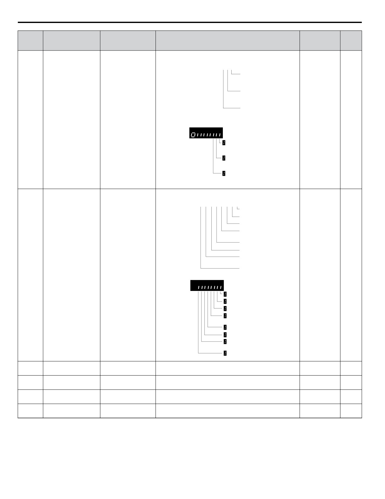
B.16 U: Monitors
No.
Analog
(Addr.
Name
LCD Display
Description
Unit
Output Level
Hex)
Displays the output terminal status.
U1 - 11= 00000000
1Multi-Function
Digital Output (fault)
(terminal MA/MB-MC)
1Multi-Function
Digital Output 1
(terminal P1) enabled
1Multi-Function
Digital Output 2
U1-11
Output Terminal
(terminal P2) enabled
No signal output
Output Term Sts
-
(004A)
Status
available
Multi-Function
Digital Output (fault)
(terminal MA/MB-MC)
Multi-Function
Digital Output 1
(terminal P1) enabled
Multi-Function
Digital Output 2
(terminal P2) enabled
Verifies the drive operation status.
U1 - 12= 0 0 0 0 0 0 0 0
1 During run
During zero-speed
1
1During REV
1During fault reset
signal input
1 During speed agree
Drive ready
1
1During alarm
detection
1
During fault detection
U1-12
No signal output
Drive Status
Int Ctl Sts 1
-
(004B)
available
During run
During zero-speed
During REV
During fault reset
signal input
During speed agree
Drive ready
During alarm
detection
During fault detection
U1-13
Terminal A1 Input
Displays the signal level to analog input terminal A1.
Term A1 Level
10 V: 100%
0.1%
(004E)
Level
U1-14
Terminal A2 Input
Displays the signal level to analog input terminal A2.
Term A2 Level
10 V: 100%
0.1%
(004F)
Level
U1-16
Output Frequency after
Displays output frequency with ramp time and S-curves. Units
10 V: Max
SFS Output
0.01 Hz
(0053)
Soft Starter
determined by o1-03.
frequency
U1-18
Displays the parameter number that caused the oPE02 operation
No signal output
oPE Fault Parameter
OPE Error Code
-
(0061)
error.
available
370
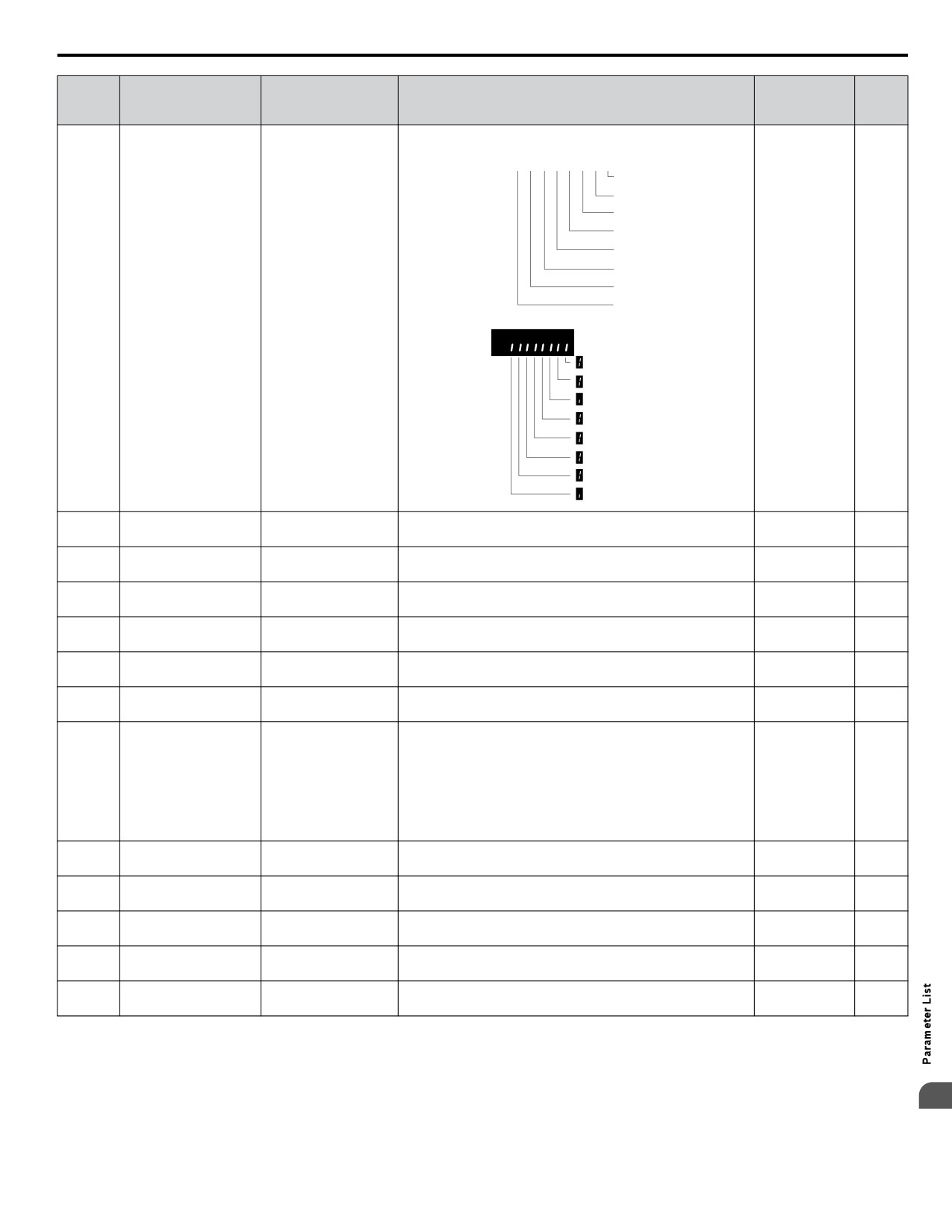
B.16 U: Monitors
No.
Analog
(Addr.
Name
LCD Display
Description
Unit
Output Level
Hex)
Displays the contents of a MEMOBUS/Modbus error.
U1 - 19= 0 0 0 0 0 0 0 0
1 CRC Error
Data Length Error
1
0Not Used
1
Parity Error
1 Overrun Error
Framing Error
1
1
Timed Out
0
Not Used
U1-19
MEMOBUS/Modbus
No signal output
Transmit Err
-
(0066)
Error Code
available
CRC Error
Data Length Error
Not Used
Parity Error
Overrun Error
Framing Error
Timed Out
Not Used
U1-24
Displays the frequency to pulse train input terminal RP.
Determined by
Input Pulse Monitor
Term RP Inp Freq
1 Hz
(007D)
H6-02
U1-25
Software Number
FLASH ID
No signal output
CPU 1 SW Number
-
(004D)
(Flash)
available
U1-26
ROM ID
No signal output
Software No. (ROM)
CPU 2 SW Number
-
(005B)
available
U1-75
Displays the current time (Hours and Minutes).
No signal output
Time-Hour/Minute
Time Hr Min HHMM
-
(0851)
available
U1-76
Displays the current year.
No signal output
Date - Year
Date Year
-
(0852)
available
U1-77
Displays the current date (Month and Date).
No signal output
Date - Month/Day
Date Mo Day MMDD
-
(0853)
available
Displays the current day of the week.
0: Sunday
1: Monday
U1-78
2: Tuesday
No signal output
Date - Week Day
Date Week
-
(0854)
3: Wednesday
available
4: Thursday
5: Friday
6: Saturday
U1-90
Displays the PID Setpoint.
No signal output
dep. on
Pump Setpoint
Pump Setpoint
(0BA5)
available
P1-02
U1-91
Displays the PID Feedback.
No signal output
dep. on
Pump Feedback
Pump Feedback
(0BA6)
available
P1-02
U1-93
Total Setpoint
Displays the total absolute Setpoint Compensation.
No signal output
dep. on
Total SP Comp.
(0BA8)
Compensation
available
P1-02
U1-94
Displays the absolute value of the output frequency (U1-02)
No signal output
Motor Speed
Motor Speed
1 RPM
(0BA9)
converted to RPM.
available
U1-99
The Anti-No-Flow reduces the output frequency when this
No signal output
Anti-No-Flow Timer
ANF Timer
0.1 s
(0BAE)
value reaches the P2-24 setting.
available
<1> Display is in the following units:
BV0006 to BV0018, 2V0006 to 2V0040, and 4V0002 to 4V0023: 0.01 A units.
2V0056 to 2V0069 and 4V0031 to 4V0038: 0.1 A units.
<2> When reading the value of this monitor via MEMOBUS/Modbus, a value of 8192 is equal to 100% of the drive rated output current.
B
<3> Values shown are specific to 200 V class drives. Double the value for 400 V class drives.
<4> This value has two decimal places (0.01 kW) if the drive is set for a maximum applicable motor capacity up to and including 11 kW, and one
decimal place (0.1 kW) if the maximum applicable motor capacity is higher than 11 kW.
371
B.16 U: Monitors
u U2: Fault Trace
No.
Analog
(Addr.
Name
LCD Display
Description
Unit
Output Level
Hex)
U2-01
Displays the current fault.
No signal output
Current Fault
Current Fault
-
(0080)
available
U2-02
Displays the previous fault.
No signal output
Previous Fault
Last Fault
-
(0081)
available
U2-03
Frequency Reference at
Displays the frequency reference at the previous fault.
No signal output
Frequency Ref
0.01 Hz
(0082)
Previous Fault
available
U2-04
Output Frequency at
Displays the output frequency at the previous fault.
No signal output
Output Freq
0.01 Hz
(0083)
Previous Fault
available
U2-05
Output Current at
Displays the output current at the previous fault.
No signal output
<2>
Output Current
<1>
(0084)
Previous Fault
available
U2-07
Output Voltage at
Displays the output voltage at the previous fault.
No signal output
Output Voltage
0.1 Vac
(0086)
Previous Fault
available
U2-08
DC Bus Voltage at
Displays the DC bus voltage at the previous fault.
No signal output
DC Bus Voltage
1 Vdc
(0087)
Previous Fault
available
U2-09
Output Power at
Displays the output power at the previous fault.
No signal output
Output kWatts
0.1 kW
(0088)
Previous Fault
available
U2-11
Input Terminal Status at
Displays the input terminal status at the previous fault.
No signal output
Input Term Sts
-
(008A)
Previous Fault
Displayed as in U1-10.
available
U2-12
Output Terminal Status
Displays the output status at the previous fault. Displays the
No signal output
Output Term Sts
-
(008B)
at Previous Fault
same status displayed in U1-11.
available
U2-13
Drive Operation Status
Displays the operation status of the drive at the previous fault.
No signal output
Inverter Status
-
(008C)
at Previous Fault
Displays the same status displayed in U1-12.
available
U2-14
Cumulative Operation
Displays the cumulative operation time at the previous fault.
No signal output
Elapsed time
1 h
(008D)
Time at Previous Fault
available
Soft Starter Speed
Displays the speed reference for the soft starter at the previous
U2-15
No signal output
Reference at Previous
SFS Output
fault.
0.01 Hz
(07E0)
available
Fault
U2-16
Motor q-Axis Current at
Displays the q-axis current for the motor at the previous fault.
No signal output
Motor Iq Current
0.10%
(07E1)
Previous Fault
available
U2-30
Date Year at Previous
Displays the year when the most recent fault occurred.
No signal output
Date Year YYYY
-
(3008)
Fault
available
U2-31
Date Month and Day at
Displays the date and day when the most recent fault occurred.
No signal output
Date Mo Day MMDD
-
(3009)
Previous Fault
available
Time Hours and
Displays the time when the most recent fault occurred.
U2-32
No signal output
Minutes at Previous
Time Hr Min HHMM
-
(300A)
available
Fault
<1> Display is in the following units:
BV0006 to BV0018, 2V0006 to 2V0040, and 4V0002 to 4V0023: 0.01 A units.
2V0056 to 2V0069 and 4V0031 to 4V0038: 0.1 A units.
<2> When reading the value of this monitor via MEMOBUS/Modbus, a value of 8192 is equal to 100% of the drive rated output current.
u U3: Fault History
No.
Analog
(Addr.
Name
LCD Display
Description
Unit
Output Level
Hex)
U3-01 to
Displays the first to the fourth most recent faults.
U3-04
First to 4th Most Recent
No signal output
(90 to 93
Fault Message o
-
Fault
available
(0800 to
0803))
Displays the fifth to the tenth most recent faults.
U3-05 to
After ten faults, data for the oldest fault is deleted. The most
U3-10
5th to 10th Most Recent
No signal output
Fault Message o
recent fault appears in U3-01, with the next most recent fault
-
(0804 to
Fault
available
appearing in U3-02. The data is moved to the next monitor
0809)
parameter each time a fault occurs.
372
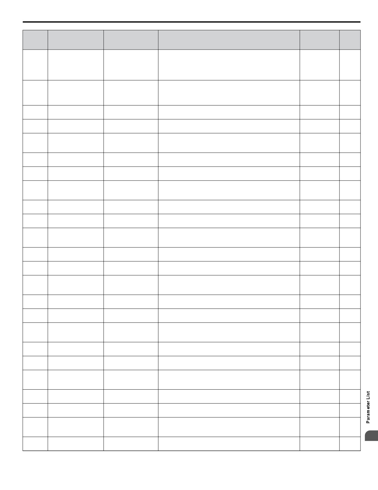
B.16 U: Monitors
No.
Analog
(Addr.
Name
LCD Display
Description
Unit
Output Level
Hex)
U3-11 to
Displays the cumulative operation time when the first to the
U3-14
Cumulative Operation
fourth most recent faults occurred.
No signal output
(94 to 97
Time at 1st to 4th Most
Elapsed Time o
1 h
available
(080A to
Recent Fault
080D))
U3-15 to
Displays the cumulative operation time when the fifth to the
Cumulative Operation
U3-20
tenth most recent faults occurred.
No signal output
Time at 5th to 10th Most
Elapsed Time o
1 h
(080E to
available
Recent Fault
0813)
U3-21
Date Year at Most
No signal output
Fault 1 YYYY
Displays the year when the most recent fault occurred.
-
(300B)
Recent Fault
available
U3-22
Date Month and Day at
No signal output
Fault 1 MMDD
Displays the date and day when the most recent faults occurred.
-
(300C)
Most Recent Fault
available
Time Hours and
U3-23
No signal output
Minutes at Most Recent
Fault 1 HHMM
Displays the time when the most recent fault occurred.
-
(300D)
available
Fault
U3-24
Date Year at 2nd Most
No signal output
Fault 2 YYYY
Displays the year when the second most recent fault occurred.
-
(300E)
Recent Fault
available
U3-25
Date Month and Day at
Displays the date and day when the second most recent fault
No signal output
Fault 2 MMDD
-
(300F)
2nd Most Recent Fault
occurred.
available
Time Hours and
U3-26
No signal output
Minutes at 2nd Most
Fault 2 HHMM
Displays the time when the second most recent fault occurred.
-
(3010)
available
Recent Fault
U3-27
Date Year at 3rd Most
No signal output
Fault 3 YYYY
Displays the year when the most third recent fault occurred.
-
(3011)
Recent Fault
available
U3-28
Date Month and Day at
Displays the date and day when the third most recent fault
No signal output
Fault 3 MMDD
-
(3012)
3rd Most Recent Fault
occurred.
available
Time Hours and
U3-29
No signal output
Minutes at 3rd Most
Fault 3 HHMM
Displays the time when the third most recent fault occurred.
-
(3013)
available
Recent Fault
U3-30
Date Year at 4th Most
No signal output
Fault 4 YYYY
Displays the year when the fourth most recent fault occurred.
-
(3014)
Recent Fault
available
U3-31
Date Month and Day at
Displays the date and day when the fourth most recent fault
No signal output
Fault 4 MMDD
-
(3015)
4th Most Recent Fault
occurred.
available
Time Hours and
U3-32
No signal output
Minutes at 4th Most
Fault 4 HHMM
Displays the time when the fourth most recent fault occurred.
-
(3016
available
Recent Fault
U3-33
Date Year at 5th Most
Displays the year when the fifth most recent fault occurred.
No signal output
Fault 5 YYYY
-
(3017)
Recent Fault
available
U3-34
Date Month and Day at
Displays the date and day when the fifth most recent fault
No signal output
Fault 5 MMDD
-
(3018)
5th Most Recent Fault
occurred.
available
Time Hours and
U3-35
No signal output
Minutes at 5th Most
Fault 5 HHMM
Displays the time when the fifth most recent fault occurred.
-
(3019)
available
Recent Fault
U3-36
Date Year at 6th Most
No signal output
Fault 6 YYYY
Displays the year when the sixth most recent fault occurred.
-
(301A)
Recent Fault
available
U3-37
Date Month and Day a
Displays the date and day when the sixth most recent fault
No signal output
Fault 6 MMDD
-
(301B)
6th Most Recent Fault
occurred.
available
Time Hours and
U3-38
No signal output
Minutes at 6th Most
Fault 6 HHMM
Displays the time when the sixth most recent fault occurred.
-
(301C)
available
Recent Fault
U3-39
Date Year at 7th Most
No signal output
Fault 7 YYYY
Displays the year when the seventh most recent fault occurred.
-
(301D)
Recent Fault
available
U3-40
Date Month and Day at
Displays the date and day when the seventh most recent fault
No signal output
Fault 7 MMDD
-
(301E)
7th Most Recent Fault
occurred.
available
Time Hours and
U3-41
No signal output
Minutes at 7th Most
Fault 7 HHMM
Displays the time when the seventh most recent fault occurred.
-
(301F)
available
Recent Fault
B
U3-42
Date Year at 8th Most
No signal output
Fault 8 YYYY
Displays the year when the eighth most recent fault occurred.
-
(3020)
Recent Fault
available
373
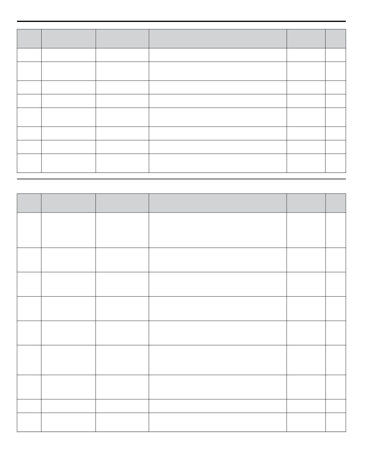
B.16 U: Monitors
No.
Analog
(Addr.
Name
LCD Display
Description
Unit
Output Level
Hex)
U3-43
Date Month and Day
Displays the date and day when the eighth most recent fault
No signal output
Fault 8 MMDD
-
(3021)
8th at Most Recent Fault
occurred.
available
Time Hours and
U3-44
No signal output
Minutes at 8th Most
Fault 8 HHMM
Displays the time when the eighth most recent fault occurred.
-
(3022)
available
Recent Fault
U3-45
Date Year at 9th Most
No signal output
Fault 9 YYYY
Displays the year when the ninth most recent fault occurred.
-
(3023)
Recent Fault
available
U3-46
Date Month and Day at
Displays the date and day when the ninth most recent fault
No signal output
Fault 9 MMDD
-
(3024)
9th Most Recent Fault
occurred.
available
Time Hours and
U3-47
No signal output
Minutes at 9th Most
Fault 9 HHMM
Displays the time when the ninth most recent fault occurred.
-
(3025)
available
Recent Fault
U3-48
Date Year at 10th Most
No signal output
Fault 10 YYYY
Displays the year when the tenth most recent fault occurred.
-
(3026)
Recent Fault
available
U3-49
Date Month and Day at
Displays the date and day when the tenth most recent fault
No signal output
Fault 10 MMDD
-
(3027)
10th Most Recent Fault
occurred.
available
Time Hours and
U3-50
No signal output
Minutes at 10th Most
Fault 10 HHMM
Displays the time when the tenth most recent fault occurred.
-
(3028)
available
Recent
u U4: Maintenance Monitors
No.
Analog
(Addr.
Name
LCD Display
Description
Unit
Output Level
Hex)
Displays the cumulative operation time of the drive. The value
for the cumulative operation time counter can be reset in
U4-01
Cumulative Operation
parameter o4-01. Use parameter o4-02 to determine if the
No signal output
(004C)
Drv Elapsed Time
1 h
<1>
Time
operation time should start as soon as the power is switched on
available
or only while the Run command is present. The maximum
number displayed is 99999, after which the value is reset to 0.
Displays the number of times the Run command is entered.
U4-02
Number of Run
Reset the number of Run commands using parameter o4-13.
No signal output
RUN Cmd Counter
1 Time
(0075)
Commands
This value will reset to 0 and start counting again after reaching
available
65535.
Displays the cumulative operation time of the cooling fan. The
U4-03
Cooling Fan Operation
default value for the fan operation time is reset in parameter
No signal output
(0067)
Fan Elapsed TIme
1 h
<2>
Time
o4-03. This value will reset to 0 and start counting again after
available
reaching 99999.
Displays main cooling fan usage time as a percentage of its
U4-04
Cooling Fan
expected performance life. Parameter o4-03 can be used to reset
No signal output
Fan Life Mon
1%
(007E)
Maintenance
this monitor.
available
Replace the fan when this monitor reaches 90%.
Displays main circuit capacitor usage time as a percentage of
U4-05
their expected performance life. Parameter o4-05 can be used
No signal output
Capacitor Maintenance
Cap Life Mon
1%
(007C)
to reset this monitor.
available
Replace the capacitor when this monitor reaches 90%.
Displays the soft charge bypass relay maintenance time as a
percentage of its estimated performance life. Parameter o4-07
U4-06
Soft Charge Bypass
No signal output
ChgCirc Life Mon
can be used to reset this monitor.
1%
(07D6)
Relay Maintenance
available
Replace the soft charge bypass relay when this monitor reaches
90%.
Displays IGBT usage time as a percentage of the expected
U4-07
performance life. Parameter o4-09 can be used to reset this
No signal output
IGBT Maintenance
IGBT Life Mon
1%
(07D7)
monitor.
available
Replace the IGBT when this monitor reaches 90%.
U4-08
Displays the heatsink temperature.
Heatsink Temperature
Heatsink Temp
10 V: 100 °C
1 °C
(0068)
Lights all segments of the LED to verify that the display is
U4-09
No signal output
LED Check
LED Oper Check
working properly. Press the ENTER key to turn the LEDs on
-
(003C)
available
and press ESC to turn the LEDs off.
374
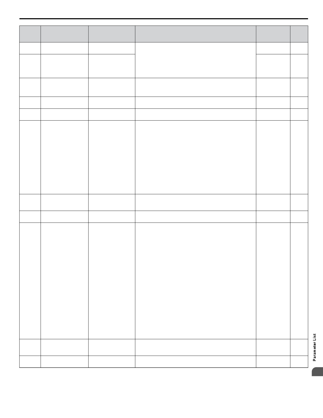
B.16 U: Monitors
No.
Analog
(Addr.
Name
LCD Display
Description
Unit
Output Level
Hex)
U4-10
Monitors the drive output power usage (or consumption). The
No signal output
kWh, Lower 4 Digits
kWh Lower 4 dig
1 kWh
(005C)
value is shown as a 9-digit number displayed across two monitor
available
parameters, U4-10 and U4-11.
Example:
U4-11
12345678.9 kWh is displayed as:
No signal output
kWh, Upper 5 Digits
kWh Upper 5 dig
1 MWh
(005D)
U4-10: 678.9 kWh
available
U4-11: 12345 MWh
Displays the highest current value that occurred during run.
0.01 A
U4-13
No signal output
Peak Hold Current
Current PeakHold
<3> <4>
(07CF)
available
<5>
U4-14
Peak Hold Output
Displays the output frequency when the current value shown in
No signal output
Freq@ I PeakHold
0.01 Hz
(07D0)
Frequency
U4-13 occurred.
available
U4-16
Motor Overload
Shows the value of the motor overload detection accumulator.
Motor OL1 Level
10 V: 100%
0.1%
(07D8)
Estimate (oL1)
100% is equal to the oL1 detection level.
Displays the source for the frequency reference as XY-nn.
X: indicates which reference is used:
1 = Reference 1 (b1-01)
2 = Reference 2 (b1-15)
Y-nn: indicates the reference source
0-01 = Digital operator
1-00 = Analog
U4-18
Frequency Reference
No signal output
Reference Source
1-01 = Analog (terminal A1)
-
(07DA)
Source Selection
available
1-02 = Analog (terminal A2)
1-03 = Analog (terminal A3)
2-02 to 17 = Multi-step speed (d1-02 to 17)
3-01 = MEMOBUS/Modbus communications
4-01 = Communication option card
5-01 = Pulse input
9-01 = Up/Down Command
Frequency Reference
Displays the frequency reference provided by MEMOBUS/
U4-19
No signal output
from MEMOBUS/
MEMOBUS Freq Ref
Modbus (decimal).
0.01%
(07DB)
available
Modbus Comm.
U4-20
Option Frequency
Displays the frequency reference input by an option card
No signal output
Option Freq Ref
-
(07DC)
Reference
(decimal).
available
Displays the source for the Run command as XY-nn.
X: Indicates which Run source is used:
1 = Reference 1 (b1-02)
Y: Input power supply data
0 = Digital operator
1 = External terminals
3 = MEMOBUS/Modbus communications
4 = Communication option card
nn: Run command limit status data
00: No limit status.
01: Run command was left on when stopped in the PRG mode
U4-21
Run Command Source
02: Run command was left on when switching from LOCAL to
No signal output
Run Cmd Source
-
(07DD)
Selection
REMOTE operation
available
03: Waiting for soft charge bypass contactor after power up (Uv
or Uv1 flashes after 10 s)
04: Waiting for “Run command prohibited” time period to end
05: Fast Stop (digital input, digital operator)
06: b1-17 (Run command given at power-up)
07: During baseblock while coast to stop with timer
08: Frequency reference is below minimal reference during
baseblock
09: Waiting for Enter command
10: Run command was switched on while copying parameters
12: Clock is being set for RTC
MEMOBUS/Modbus
Displays the drive control data set by MEMOBUS/Modbus
U4-22
No signal output
Communications
MEMOBUS Ref Reg
communications register no. 0001H as a four-digit hexadecimal
-
(07DE)
available
Reference
number.
U4-23
Communication Option
Displays drive control data set by an option card as a four-digit
No signal output
Option Ref Reg
-
(07DF)
Card Reference
hexadecimal number.
available
<1> The MEMOBUS/Modbus communications data is in 10 h units. If data in 1 h units are also required, refer to register number 0099H.
B
<2> The MEMOBUS/Modbus communications data is in 10 h units. If data in 1 h units are also required, refer to register number 009BH.
<3> Display is in the following units:
375
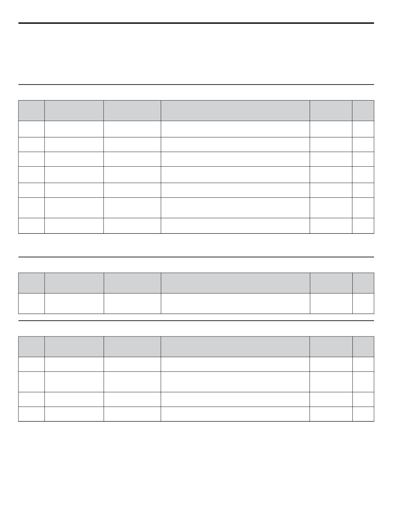
B.16 U: Monitors
BV0006 to BV0018, 2V0006 to 2V0040, and 4V0002 to 4V0023: 0.01 A units.
2V0056 to 2V0069 and 4V0031 to 4V0038: 0.1 A units.
<4> The values of U1-03, U2-05, and U4-13 are displayed on the digital operator in units of amperes. When those monitors are checked using
MEMOBUS/Modbus communications, the monitor values in MEMOBUS/Modbus communications are displayed as: numeric value / 8192 × drive
rated current (A) from the condition “192 (maximum value) = drive rated current (A)”
<5> When reading the value of this monitor via MEMOBUS/Modbus a value of 8192 is equal to 100% of the drive rated output current.
u U5: PID Monitors
No.
Analog
(Addr.
Name
LCD Display
Description
Unit
Output Level
Hex)
U5-01
Displays the PID feedback value.
0.01%
PID Feedback 1
PID Feedback 1
10 V: 100%
(0057)
<1>
U5-02
Displays the amount of PID input (deviation between PID
PID Input
PID Input
10 V: 100%
0.01%
(0063)
setpoint and feedback).
U5-03
Displays PID control output.
PID Output
PID Output
10 V: 100%
0.01%
(0064)
U5-04
Displays the PID setpoint.
0.01%
PID Setpoint
PID Setpoint
10 V: 100%
(0065)
<1>
U5-05
PID Differential
Displays the 2nd PID feedback value if differential feedback is
PID Feedback 2
10 V: 100%
0.01%
(07D2)
Feedback
used (H3-oo = 16).
Displays the difference of both feedback values if differential
U5-06
PID Adjusted Feedback
PID Diff Fdbk
feedback is used (U5-01 - U5-05). If differential feedback is not
10 V: 100%
0.01%
(07D3)
used, then U5-01 and U5-06 will be the same.
U5-99
Displays the PID Setpoint commanded by the source when the
No signal output
0.01%
AUTO Setpoint
Auto Setpoint
<1>
(1599)
drive is in AUTO Mode.
available
<1> Unit is determined by P1-02, System Units; scaling is determined by P1-03, Feedback Device Scaling; resolution is determined by b5-39, PID
System Units Display Digits.
u U6: Control Monitors
No.
Analog
(Addr.
Name
LCD Display
Description
Unit
Output Level
Hex)
Displays the value of the motor secondary current (Iq). Motor
10 V: Motor
U6-01
Motor Secondary
Mot SEC Current
rated secondary current is 100%.
secondary rated
0.1%
(0051)
Current (Iq)
current
u U9: Operation Status Monitors
No.
Analog
(Addr.
Name
LCD Display
Description
Unit
Output Level
Hex)
U9-01
Displays the network PID feedback recognized by the iQpump
No signal output
Dep. on
Network PID Feedback
Net PI Feedback
(1901)
MEMOBUS network.
available
P1-02
Displays network traffic. A fluctuating number from 0 to 10000
U9-02
No signal output
<1>
Network Activity
iQ Net Activity
denotes activity, while a relatively constant 0 denotes no
(1902)
available
activity.
U9-03
Displays the time remaining before a drive requests the
No signal output
Time to Alternate
Time to Alternate
min
(1903)
alternation mode set in P9-04.
available
U9-04
Running Queue
Displays the position in the iQPump MEMOBUS Multiplex
No signal output
Running Queue No
-
(1904)
Number
running queue.
available
<1> Unit changes based on network status.
<->: Drive cannot communicate to other drives
<+>: Drive is a node on a network
<M>: Drive is the master on an iQpump network.
376
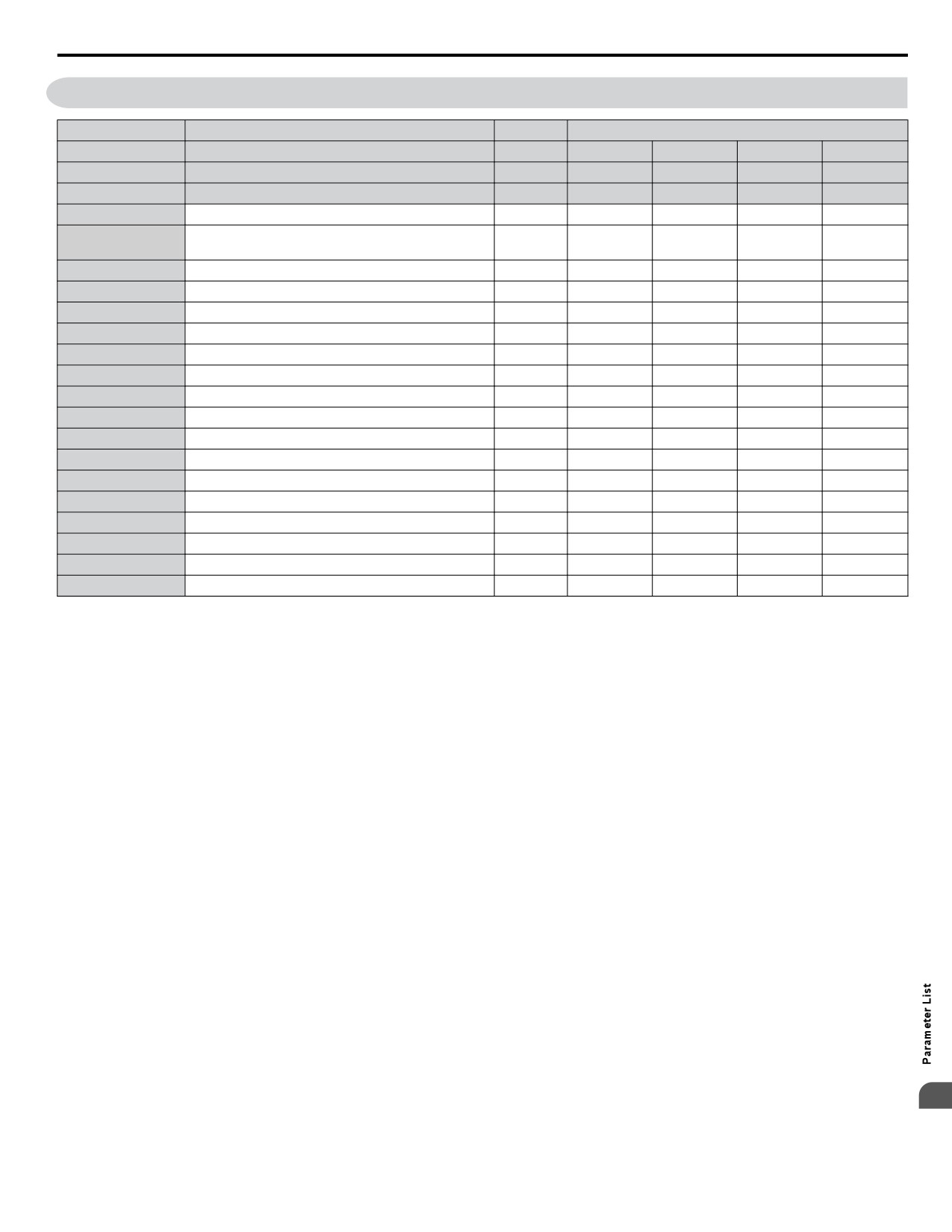
B.17 Defaults by Drive Model
B.17 Defaults by Drive Model
No.
Description
Unit
Default Settings
−
Model
−
BV0006
BV0010
BV0012
BV0018
o2-04
Drive Model Selection
Hex
33
34
35
37
E2-11
Motor Rated Power
kW
1.1
2.2
3.0
3.7
b3-06
Speed Search current 1
−
0.5
0.5
0.5
0.5
Current Control Gain during Speed Search (Speed
b3-08
-
0.5
0.5
0.5
0.5
Estimation Type)
C6-02
Carrier frequency
−
7
7
7
3
E2-01
Motor rated current
A
6.2
8.5
11.4
14.0
E2-02
Motor rated slip
Hz
2.6
2.9
2.7
2.73
E2-03
Motor no-load current
A
2.8
3
3.7
4.5
E2-05
Motor line-to-line resistance
Ω
1.997
1.601
1.034
0.771
E2-06
Motor leakage inductance
%
18.5
18.4
19
19.6
E2-10
Motor Iron Loss
W
53
77
91
112
L2-02
Momentary power loss ride-through time
s
0.2
0.3
0.5
1.0
L2-03
Momentary power loss Baseblock time
s
0.4
0.5
0.5
0.6
L2-04
Momentary power loss voltage recovery time
s
0.3
0.3
0.3
0.3
L2-05
Uv detection voltage
V dc
160
160
160
160
L3-24
Motor acceleration time
s
0.142
0.145
0.145
0.154
L8-02
Overheat alarm level
°C
105
100
95
100
L8-09
Ground fault selection
−
0
0
0
0
L8-38
Carrier frequency reduction selection
−
1
1
1
1
n1-03
Hunting Prevention Time Constant
ms
10
10
10
10
B
377
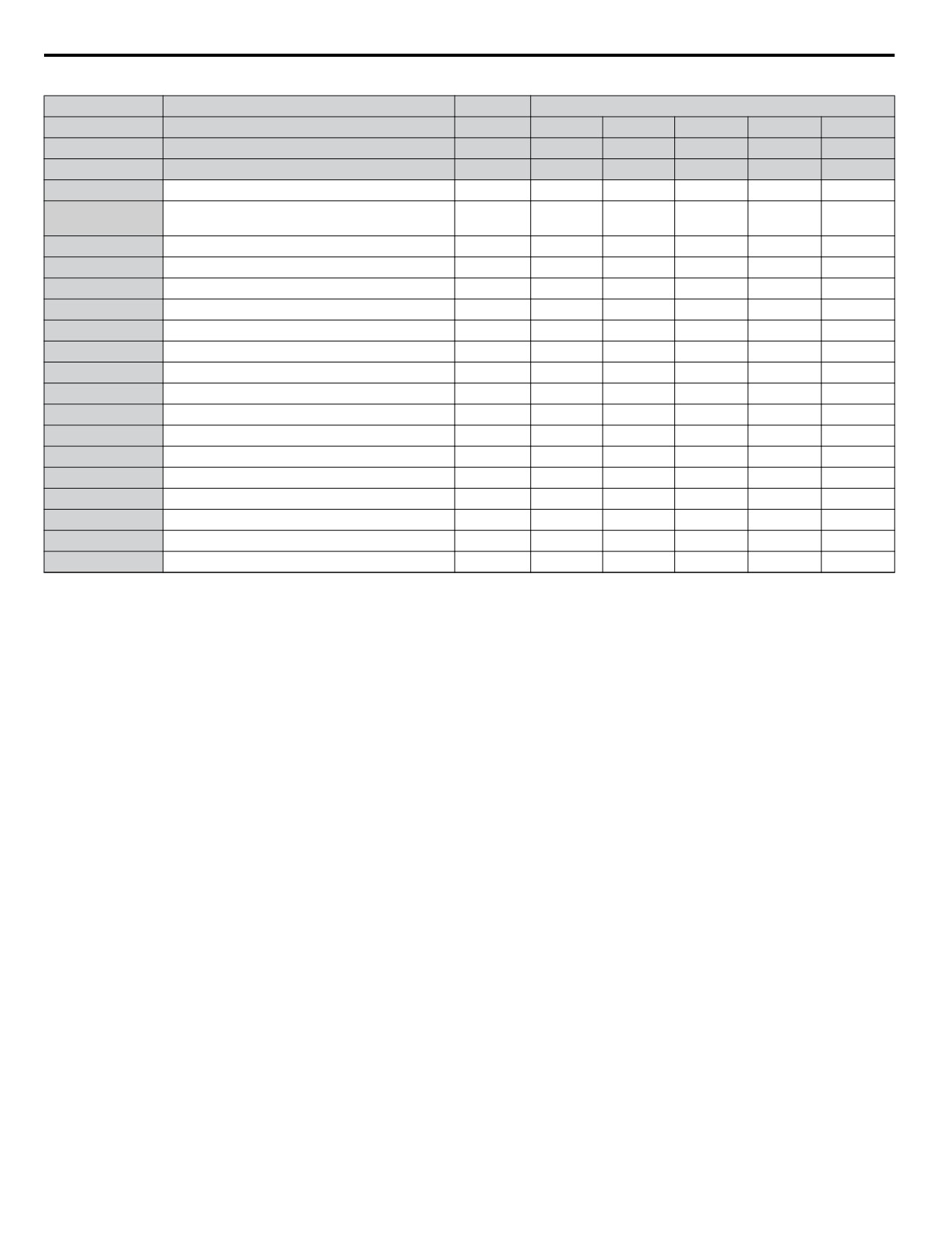
B.17
Defaults by Drive Model
Table B.4 Three-Phase, 200 V Class Drives Default Settings by Drive Capacity
No.
Description
Unit
Default Settings
−
Model
−
2V0006
2V0010
2V0012
2V0020
2V0030
o2-04
Drive Model Selection
Hex
63
65
66
68
6A
E2-11
Motor Rated Power
kW
1.1
2.2
3.0
5.5
7.5
b3-06
Speed Search current 1
−
0.5
0.5
0.5
0.5
0.5
Current Control Gain during Speed Search (Speed
b3-08
-
0.5
0.5
0.5
0.5
0.5
Estimation Type)
C6-02
Carrier frequency
−
7
7
7
7
7
E2-01
Motor rated current
A
4.9
8.5
11.4
19.6
26.6
E2-02
Motor rated slip
Hz
2.6
2.9
2.7
1.5
1.3
E2-03
Motor no-load current
A
2.3
3.0
3.7
5.1
8.0
E2-05
Motor line-to-line resistance
Ω
3.577
1.601
1.034
0.399
0.288
E2-06
Motor leakage inductance
%
18.5
18.4
19
18.2
15.5
E2-10
Motor Iron Loss
W
38
77
91
172
262
L2-02
Momentary power loss ride-through time
s
0.2
0.3
0.5
1
1.0
L2-03
Momentary power loss Baseblock time
s
0.4
0.5
0.5
0.7
0.8
L2-04
Momentary power loss voltage recovery time
s
0.3
0.3
0.3
0.6
0.6
L2-05
Uv detection voltage
V dc
190
190
190
190
190
L3-24
Motor acceleration time
s
0.142
0.145
0.145
0.168
0.175
L8-02
Overheat alarm level
°C
100
100
100
110
115
L8-09
Ground fault selection
−
0
0
0
0
1
L8-38
Carrier frequency reduction selection
−
1
1
1
1
2
n1-03
Hunting Prevention Time Constant
ms
10
10
10
10
10
378
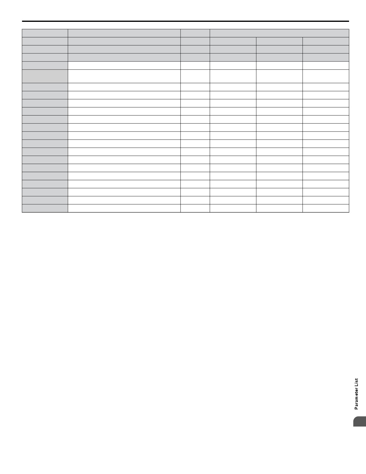
B.17 Defaults by Drive Model
No.
Description
Unit
Default Settings
−
Model
−
2V0040
2V0056
2V0069
o2-04
Drive Model Selection
Hex
6B
6D
6E
E2-11
Motor rated power
kW
11.0
15.0
18.5
b3-06
Speed Search current 1
−
0.5
0.5
0.5
Current Control Gain during Speed Search (Speed
b3-08
-
0.5
0.5
0.5
Estimation Type)
C6-02
Carrier frequency
−
7
7
7
E2-01
Motor rated current
A
39.7
53
65.8
E2-02
Motor rated slip
Hz
1.7
1.6
1.67
E2-03
Motor no-load current
A
11.2
15.2
15.7
E2-05
Motor line-to-line resistance
Ω
0.230
0.138
0.101
E2-06
Motor leakage inductance
%
19.5
17.2
15.7
E2-10
Motor Iron Loss
W
245
272
505
L2-02
Momentary power loss ride-through time
s
1.0
2.0
2.0
L2-03
Momentary power loss Baseblock time
s
0.9
1.0
1.0
L2-04
Momentary power loss voltage recovery time
s
0.3
0.3
0.6
L2-05
Uv detection voltage
V dc
190
190
190
L3-24
Motor acceleration time
s
0.265
0.244
0.317
L8-02
Overheat alarm level
°C
121
120
120
L8-09
Ground fault selection
−
1
1
1
L8-38
Carrier frequency reduction selection
−
2
2
2
n1-03
Hunting Prevention Time Constant
ms
10
10
10
B
379
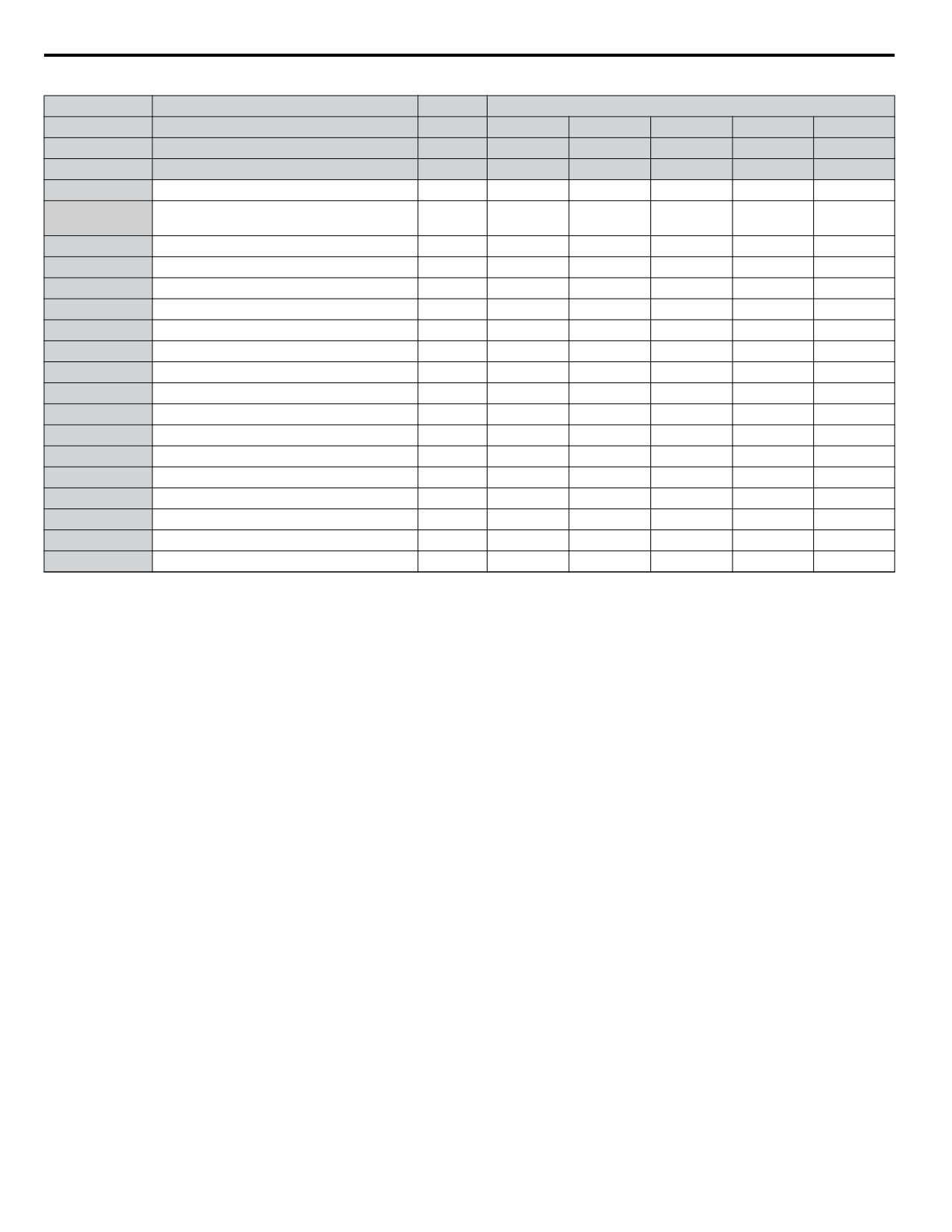
B.17 Defaults by Drive Model
Table B.5 Three-Phase 400 V Class Drives Default Settings by Drive Capacity
No.
Description
Unit
Default Settings
−
Model
−
4V0002
4V0004
4V0005
4V0007
4V0009
o2-04
Drive Model Selection
Hex
92
93
94
95
96
E2-11
Motor rated power
kW
0.75
1.5
2.2
3.0
3.7
b3-06
Speed Search current 1
−
0.5
0.5
0.5
0.5
0.5
Current Control Gain during Speed Search
b3-08
-
0.5
0.5
0.5
0.5
0.5
(Speed Estimation Type)
C6-02
Carrier frequency
−
7
7
7
7
7
E2-01
Motor rated current
A
1.6
3.1
4.2
5.7
7
E2-02
Motor rated slip
Hz
2.6
2.5
3
2.7
2.7
E2-03
Motor no-load current
A
0.8
1.4
1.5
1.9
2.3
E2-05
Motor line-to-line resistance
Ω
22.459
10.1
6.495
4.360
3.333
E2-06
Motor leakage inductance
%
14.3
18.3
18.7
19
19.3
E2-10
Motor Iron Loss
W
26
53
77
105
130
L2-02
Momentary power loss ride-through time
s
0.1
0.2
0.3
0.5
0.5
L2-03
Momentary power loss Baseblock time
s
0.3
0.4
0.5
0.5
0.6
L2-04
Momentary power loss voltage recovery time
s
0.3
0.3
0.3
0.3
0.3
L2-05
Uv detection voltage
V dc
380
380
380
380
380
L3-24
Motor acceleration time
s
0.142
0.166
0.145
0.145
0.154
L8-02
Overheat alarm level
°C
110
110
90
100
100
L8-09
Ground fault selection
−
0
0
0
0
0
L8-38
Carrier frequency reduction selection
−
1
1
1
1
1
n1-03
Hunting Prevention Time Constant
ms
10
10
10
10
10
380
B.17 Defaults by Drive Model
No.
Description
Unit
Setting Range
−
Model
−
4V0011
4V0018
4V0023
4V0031
4V0038
o2-04
Drive Model Selection
−
97
99
9A
9C
9D
E2-11
Motor Rated Power
kW
5.5
7.5
11.0
15.0
18.5
b3-06
Speed Search current 1
−
0.5
0.5
0.5
0.5
0.5
Current Control Gain during Speed Search
b3-08
-
0.5
0.5
0.5
0.5
0.5
(Speed Estimation Type)
C6-02
Carrier frequency
−
7
7
7
7
7
E2-01
Motor rated current
A
9.8
13.30
19.9
26.5
32.9
E2-02
Motor rated slip
Hz
1.5
1.3
1.70
1.60
1.67
E2-03
Motor no-load current
A
2.6
4.0
5.6
7.6
7.8
E2-05
Motor line-to-line resistance
Ω
1.595
1.152
0.922
0.550
0.403
E2-06
Motor leakage inductance
%
18.2
15.5
19.6
17.2
20.1
E2-10
Motor Iron Loss
W
193
263
385
440
508
L2-02
Momentary power loss ride-through time
s
0.5
0.8
1
2
2
L2-03
Momentary power loss Baseblock time
s
0.7
0.8
0.9
1.0
1.0
L2-04
Momentary power loss voltage recovery time
s
0.3
0.3
0.3
0.6
0.6
L2-05
Uv detection voltage
V dc
380
380
380
380
380
L3-24
Motor acceleration time
s
0.154
0.175
0.265
0.244
0.317
L8-02
Overheat alarm level
°C
100
110
110
110
110
L8-09
Ground fault selection
−
0
1
1
1
1
L8-38
Carrier frequency reduction selection
−
1
2
2
2
2
n1-03
Hunting Prevention Time Constant
ms
10
10
10
10
10
B
381
B.17 Defaults by Drive Model
This Page Intentionally Blank
382
Appendix: C
MEMOBUS/Modbus Communications
C.1
SECTION SAFETY
384
C.2
MEMOBUS/MODBUS CONFIGURATION
385
C.3
COMMUNICATION SPECIFICATIONS
386
C.4
CONNECTING TO A NETWORK
387
C.5
MEMOBUS/MODBUS SETUP PARAMETERS
391
C.6
DRIVE OPERATIONS BY MEMOBUS/MODBUS
395
C.7
COMMUNICATIONS TIMING
396
C.8
MESSAGE FORMAT
397
C.9
MESSAGE EXAMPLES
399
C.10 MEMOBUS/MODBUS DATA TABLE
401
C.11 ENTER COMMAND
415
C.12 COMMUNICATION ERRORS
416
C.13 SELF-DIAGNOSTICS
417
383
C.1 Section Safety
C.1
Section Safety
DANGER
Electrical Shock Hazard
Do not connect or disconnect wiring while the power is on.
Failure to comply will result in death or serious injury.
Before servicing, disconnect all power to the equipment. The internal capacitor remains charged even after the power supply
is turned off. The charge indicator LED will extinguish when the DC bus voltage is below 50 Vdc. To prevent electric shock,
wait at least one minute after all indicators are OFF and measure the DC bus voltage level to confirm safe level.
WARNING
Do not operate equipment with covers removed.
Failure to comply could result in death or serious injury.
Do not perform work on the drive while wearing loose clothing, jewelry or without eye protection.
Failure to comply could result in death or serious injury.
Remove all metal objects such as watches and rings, secure loose clothing and wear eye protection before beginning work
on the drive.
Do not remove covers or touch circuit boards while the power is on.
Failure to comply could result in death or serious injury.
Do not allow unqualified personnel to use equipment.
Failure to comply could result in death or serious injury.
Maintenance, inspection and replacement of parts must be performed only by authorized personnel familiar with installation,
adjustment and maintenance of AC drives.
Before wiring terminals, disconnect all power to the equipment.
The internal capacitor remains charged even after the power supply is turned off. The charge indicator LED will extinguish
when the DC bus voltage is below 50 Vdc. To prevent electric shock, wait at least one minute after all indicators are OFF
and measure the DC bus voltage level to confirm safe level.
Fire Hazard
Tighten all terminal screws to the specified tightening torque.
Loose electrical connections could result in death or serious injury by fire due to overheating of electrical connections.
CAUTION
Crush Hazard
Do not carry the drive by the front cover.
Failure to comply may result in minor or moderate injury from the main body of the drive falling.
NOTICE
Observe proper electrostatic discharge procedures (ESD) when handling the drive and circuit boards.
Failure to comply may result in ESD damage to the drive circuitry.
Check all the wiring to ensure that all connections are correct after installing the drive and connecting any other
devices.
Failure to comply could result in damage to the drive.
384
C.2 MEMOBUS/Modbus Configuration
C.2
MEMOBUS/Modbus Configuration
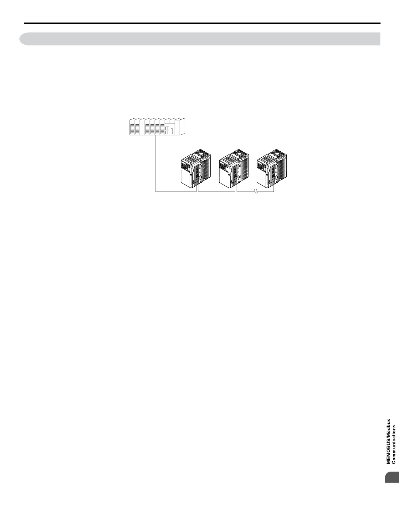
Drives can be controlled from a PLC or other master device via serial communications using the MEMOBUS/Modbus protocol.
MEMOBUS/Modbus communication can be configured using one master (PLC) and a maximum of 255 slaves. The drive has
slave functionality only, meaning that serial communication is normally initiated from the master and responded to by the
slaves.
The master performs serial communications with only one slave at a time. The address or node for each slave must be set
beforehand so that the master can communicate with the slave at that address. A slave that receives a command from the master
will perform the specified function and then send a response back to the master.
Master (PLC or other)
DRIVE
DRIVE
DRIVE
Figure C.1 Connecting Multiple Drives to a PLC
C
385
C.3 Communication Specifications
C.3
Communication Specifications
MEMOBUS/Modbus specifications appear in the following table:
Item
Specifications
Interface
RS-422, RS-485
Communications Cycle
Asynchronous (Start-stop synchronization)
Communication Speeds
1.2; 2.4; 4.8; 9.6; 19.2; 38.4; 57.6; 76.8; 115.2 kbps
Available
Communication
Data length
8 bit (fixed)
Parameters
Parity
Select even, odd, or none
Stop bit
1 bit (fixed)
Protocol
MEMOBUS/Modbus (using RTU mode only)
Max Number of Slaves
31 drives
386
C.4 Connecting to a Network
C.4
Connecting to a Network
This section explains the connection of a drive to a MEMOBUS/Modbus network and the network termination.
u Network Cable Connection
Follow the instructions below to connect the drive to a MEMOBUS/Modbus network.
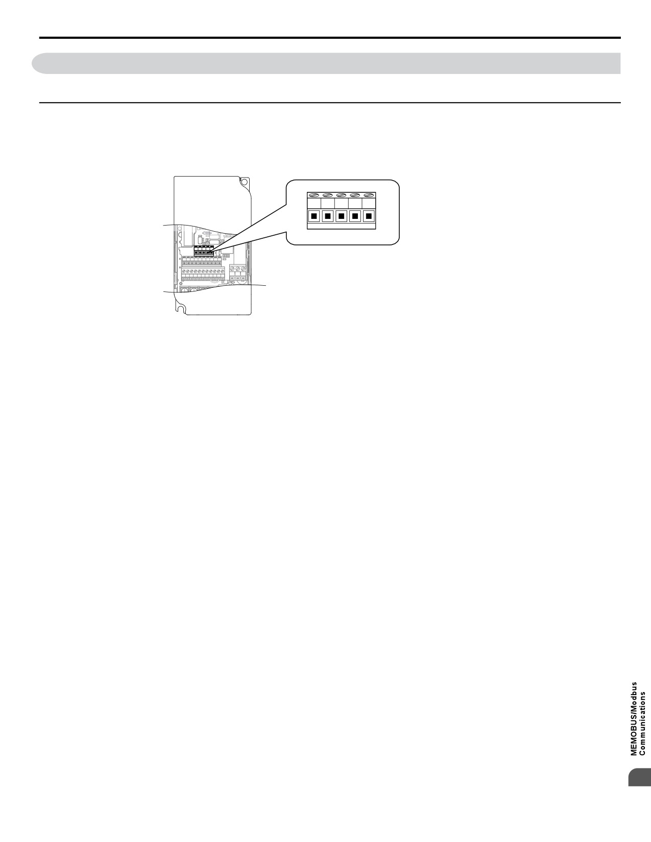
1. With the power shut off, connect the communications cable to the drive and the master. Use the terminals shown in
the figure below for network cable connections.
R+
R-
S+
S-
IG
R+ R㸫 S+ S㸫 IG
P1
P2
PC A1
A2
+V AC AM AC MP
R+ Receive (+)
S1
S2
S3
S4
S5
S6
S7
HC SC H1
RP
MA MB MC
R-
Receive (-)
S+
Send (+)
S-
Send (-)
IG
Shield Ground
Figure C.2 Serial Communications Cable Connection Terminals
Note:
Separate the communications cables from the main circuit cables and other wiring and power cables. Use shielded cables for
the communications cables, and properly shielded clamps to prevent problems with noise. When using RS-485
communications, connect S+ to R+, and S- to R- as shown in the diagram below.
2. Check or set the terminating resistance at all slaves. Use the description in Network Termination for slaves that are
1000 series drives.
3. Switch the power on.
4. Set the parameters needed for serial communications (H5-01 through H5-12) using the LED operator.
5. Shut the power off and wait until the display on the LED operator goes out completely.
6. Turn the power back on.
7. The drive is now ready to begin communicating with the master.
C
387
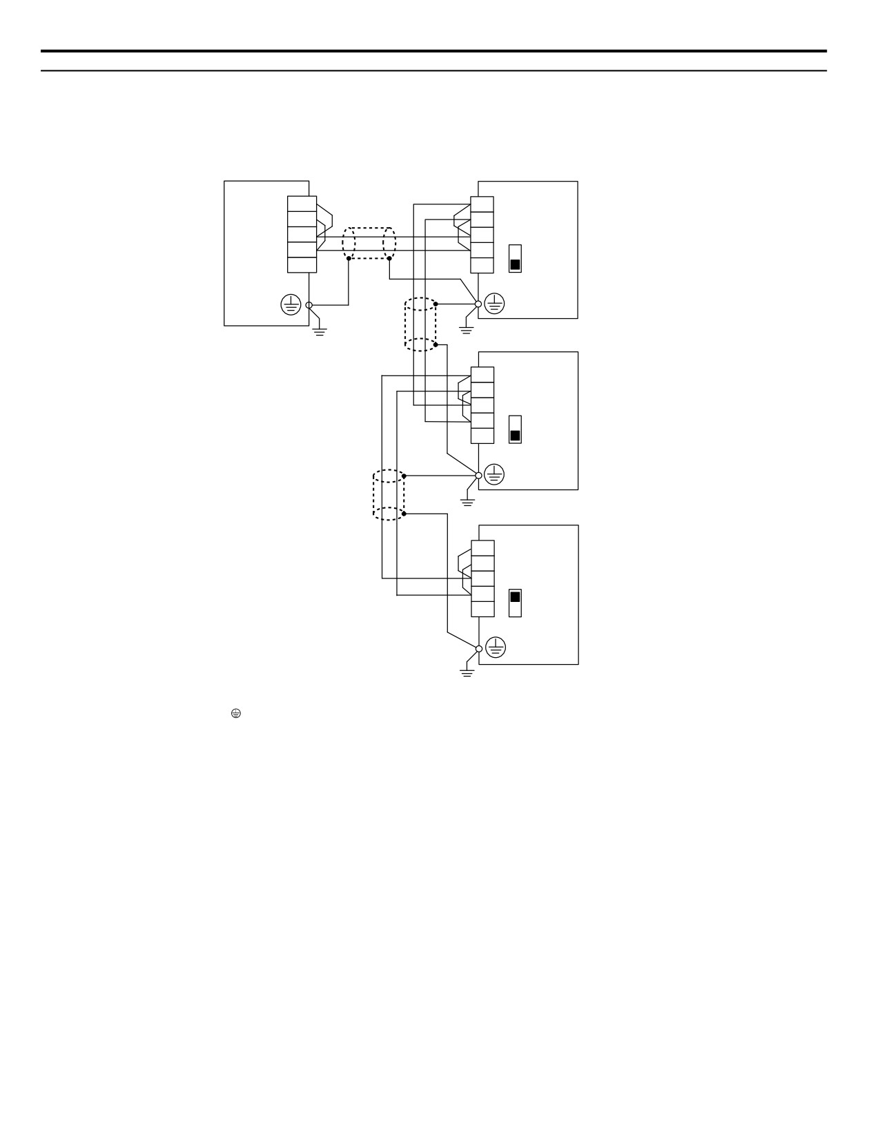
C.4 Connecting to a Network
u Wiring Diagram for Multiple Connections
Figure C.3 and Figure C.4 explain the wiring diagrams for multiple connections using MEMOBUS/Modbus communication.
n RS-485 Interface
Note:
The isolated ground (IG) connection is optional but strongly recommended to improve network immunity to electrical interference.
R-
S-
Drive
R+
S+
S-
R-
Controller
S2
S+
R+
IG
<2>
<2>
IG
OFF
<1>
<1>
S-
Drive
S+
R-
S2
R+
<2>
IG
OFF
<1>
S-
Drive
S+
R-
S2
R+
ON
<2>
IG
<1>
<1> The Ground symbol represents a direct electrical connection to the Earth.
Connect the shield to ground at the controller side only if common mode noise issues are suspected.
<2> The IG terminal is the signal common point for the RS-485 transceiver chip power supply.
Connect the isolated ground IG between all nodes to help prevent the coupling of external noise
to the bus and to limit bus emissions if desired.
Figure C.3 RS-485 Interface
Note:
1. Set DIP switch S2 to the ON position on the drive located at the end of the network. Set DIP switch S2 to the OFF positions on all other
slave devices.
2. Set H5-07 to 1 when using the RS-485 interface.
388
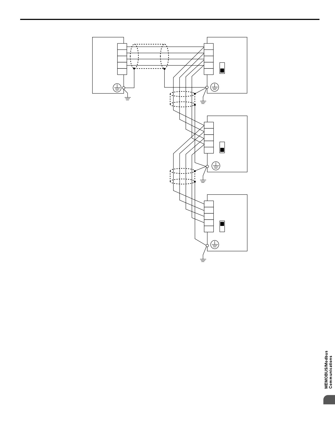
C.4 Connecting to a Network
n RS-422 Interface
R-
S-
Drive
R+
S+
PLC
S-
R-
S2
S+
R+
IG
IG
OFF
S-
Drive
S+
R-
S2
R+
IG
OFF
S-
Drive
S+
R-
S2
R+
ON
IG
Figure C.4 RS-422 Interface
Note:
1. Set DIP switch S2 to the ON position on the drive located at the end of the network. Set DIP switch S2 to the OFF positions on all other
slave devices.
2. Set H5-07 to 1 when using the RS-422 interface in a multi-drop circuit.
Set H5-07 to 0 when using the RS-422 interface in a point-to-point circuit.
C
389

C.4 Connecting to a Network
u Network Termination
The two ends of the MEMOBUS/Modbus network line have to be terminated. The drive has a built in terminating resistance
that can be enabled or disabled using DIP switch S2. If a drive is located at the end of a network line, enable the terminating
resistance by setting DIP switch S2 to the ON position. Disable the terminating resistance on all slaves that are not located at
the network line end. Figure C.5 illustrates the setting of DIP switch S2.
DIP switch S2
S+
+
(in the ON position)
OFF ON
-
S-
RS-422A
R+ R㸫 S+ S㸫 IG
or
R+
P1
P2
PC A1
A2
+V AC AM AC MP
RS-485
DIP
S1
S2
S3
S4
S5
S6
S7
HC SC H1
RP
MA MB MC
switch
R+ R- S+ S- IG
R
-
S2
terminal resistance (1/2 W, 120
)
Figure C.5 Serial Communications Terminal and DIP Switch S2
390
C.5 MEMOBUS/Modbus Setup Parameters
C.5
MEMOBUS/Modbus Setup Parameters
u MEMOBUS/Modbus Serial Communication
This section describes parameters necessary to set up MEMOBUS/Modbus communications.
n H5-01: Drive Slave Address
Sets the drive slave address used for MEMOBUS/Modbus communications.
Note:
After changing this parameter, the power must be cycled to enable the new setting.
No.
Name
Setting Range
Default
H5-01
Drive Slave Address
0 to 20 H <1>
1F
<1> If the address is set to 0, no response will be provided during communications.
For serial communications to work, each individual slave drive must be assigned a unique slave address. Setting H5-01 to any
value besides 0 assigns the drive its address in the network. Slave address don't need to be assigned in sequential order, but
each address needs to be unique so that no two drives have the same address.
n H5-02: Communication Speed Selection
Sets the MEMOBUS/Modbus communications speed.
Note:
After changing this parameter, the power must be cycled to enable the new setting.
No.
Name
Setting Range
Default
H5-02
Communication Speed Selection
0 to 5
3
H5-02
Communication Speed
H5-02
Communication Speed
0
1200 bps
5
38400 bps
1
2400 bps
6
57600 bps
2
4800 bps
7
76800 bps
3
9600 bps
8
115200 bps
4
19200 bps
-
n H5-03: Communication Parity Selection
Sets the parity used for MEMOBUS/Modbus communications.
Note:
After changing this parameter, the power must be cycled to enable the new setting.
No.
Name
Setting Range
Default
H5-03
Communication Parity Selection
0 to 2
0
Setting 0: No Parity
Setting 1: Even Parity
Setting 2: Odd Parity
C
391
C.5 MEMOBUS/Modbus Setup Parameters
n H5-04: Stopping Method after Communication Error
Selects the stopping method after a communications error (CE) has occurred.
No.
Name
Setting Range
Default
H5-04
Stopping Method after Communication Error
0 to 3
3
Setting 0: Ramp to Stop Using Current Accel/Decel Time
Setting 1: Coast to Stop
Setting 2: Fast-stop Using C1-09
Setting 3: Alarm Only, Continue Operation
n H5-05: Communication Fault Detection Selection
Enables or disabled the communication error (CE) detection for MEMOBUS/Modbus communications.
No.
Name
Setting Range
Default
H5-05
Communication Fault Detection Selection
0 or 1
1
Setting 0: Disabled
No error detection. The drive continues operation.
Setting 1: Enabled
If the drive does not receive data from the master for longer than the time set to H5-09, then a CE fault will be triggered and
the drive will operate as determined by parameter H5-04.
n H5-06: Drive Transmit Wait Time
Sets the time the drive waits after receiving data from a master until responding data.
No.
Name
Setting Range
Default
H5-06
Drive Transmit Wait Time
5 to 65 ms
5 ms
PLCЍDrive
DriveЍPLC
PLCЍDrive
Command message
Response message
Command message
Time
24 bit length H5-06 setting
Figure C.6 Drive Transmit Wait Time Setting
n H5-07: RTS Control Selection
Enables or disables RTS control.
No.
Name
Setting Range
Default
H5-07
RTS Control Selection
0 or 1
1
Setting 0: Disabled - RTS is Always ON
Use this setting when using RS-422 signals for communications (1:1).
Setting 1: Enabled - RTS Switches while Sending
Use this setting when using RS-485 signals for communications or when using the RS-422 signals for multi-drop
communications.
n H5-09: CE Detection Time
Sets the time the communications must be lost before the drive triggers a CE fault.
No.
Name
Setting Range
Default
H5-09
CE Detection Time
0.0 to 10.0 s
2.0 s
392
C.5 MEMOBUS/Modbus Setup Parameters
n H5-10: Unit Selection for MEMOBUS/Modbus Register 0025H
Sets the unit for the output voltage monitor value in MEMOBUS/Modbus register 0025H.
No.
Name
Setting Range
Default
H5-10
Unit Selection for MEMOBUS/Modbus Register 0025H
0 or 1
0
Setting 0: 0.1 V Units
Setting 1: 1 V Units
C
393
C.5 MEMOBUS/Modbus Setup Parameters
n H5-11: Communications Enter Function Selection
Selects if an Enter command is needed to change parameter values via MEMOBUS/Modbus communications. Refer to Enter
Command on page 415.
No.
Name
Setting Range
Default
H5-11
Communications Enter Function Selection
0 or 1
0
Setting 0: Enter command necessary
Parameter changes become effective after an Enter command. An Enter command must only be sent after the last parameter
change, not for each single parameter.
Setting 1: Enter command not necessary
Parameter value changes become effective immediately without the need to send an Enter command.
n H5-12: Run Command Method Selection
Selects the type of sequence used when the Run command source is set to MEMOBUS/Modbus communications
(b1-02/16 = 2).
No.
Name
Setting Range
Default
H5-12
Run Command Method Selection
0 or 1
0
Setting 0: FWD/Stop, REV/Stop
Bit 0 of MEMOBUS/Modbus register 0001H will start and stop the drive in the forward direction. Bit 1 will start and stop the
drive in reverse.
Setting 1: Run/Stop, FWD/REV
Bit 0 of MEMOBUS/Modbus register 0001H will start and stop the drive. Bit 1 changes the direction.
394
C.6 Drive Operations by MEMOBUS/Modbus
C.6
Drive Operations by MEMOBUS/Modbus
The drive operations that can be performed by MEMOBUS/Modbus communication depend on drive parameter settings. This
section explains the functions that can be used and related parameter settings.
u Observing the Drive Operation
A PLC can perform the following actions with MEMOBUS/Modbus communications at any time regardless of parameter
settings (except H5-oo).
• Observe drive status and drive control terminal status from a PLC.
• Read and write parameters.
• Set and reset faults.
• Set multi-function inputs. Inputs settings from the input terminals So and from MEMOBUS/Modbus communications are
both linked by an OR operation.
u Controlling the Drive
To start and stop the drive or set the frequency reference using MEMOBUS/Modbus communications, an external reference
must be selected and the parameters listed below must be adjusted accordingly.
Table C.1 Setting Parameters for Drive Control from MEMOBUS/Modbus
Reference Source
Parameter
Name
Required Setting
b1-01
Frequency Reference Selection 1
2
External Reference 1
b1-02
Run Command Selection 1
2
b1-15
Frequency Reference Selection 2
2
External Reference 2
b1-16
Run Command Selection 2
2
Refer to b1-01: Frequency Reference Selection 1 on page 115 and Refer to b1-02: Run Command Selection 1 on page
118 for details on external reference parameter selections. Refer to Setting 2: External Reference 1/2 Selection on page
164 for instructions on how to select external reference 1 and 2.
C
395
C.7 Communications Timing
C.7
Communications Timing
To prevent overrun in the slave drive, the master should wait a certain time between sending messages to the same drive. In
the same way, the slave drive must wait before sending response messages to prevent an overrun in the master. This section
explains the message timing.
u Command Messages from Master to Drive
In order to prevent overrun and data loss, the master must wait between receiving a response and sending the same type of
command as before to the same slave drive. The minimum wait time depends on the command as shown in the table below.
Table C.2 Minimum Wait Time for Sending Messages
Command Type
Example
Minimum Wait Time
• Control command (Run, Stop)
1
• Set inputs/outputs
5 ms
• Read monitors and parameter values
H5-11 = 0: 50 ms
2
• Write parameters
H5-11 = 1: 200 ms <1>
200 ms to 2 s, depending on the number
3
• Save changes using an Enter command
of changed parameters <1>
<1> If the drive receives command type 1 data during the minimum wait time, it will perform the command and then respond. However, if it receives
a command type 2 or 3 during that time, either a communication error will result or the command will be ignored.
PLC→Drive
Drive→PLC
PLC→Drive
Command message
Response message
Command message
Time
Master Send
24 bit length
Wait Time
Figure C.7 Minimum Wait Time for Sending Messages
A timer should be set in the master to check how long it takes for the slave drive(s) to respond to the master. If no response
is received within a certain amount of time, the master should try resending the message.
u Response Messages from Drive to Master
If the drive receives a command from the master, it will process the data received and wait for the time set in H5-06 until it
responds. Increase H5-06 if the drive response causes overrun in the master.
PLC→Drive
Drive→PLC
PLC→Drive
Command message
Response message
Command message
Time
24 bit length
H5-06
setting
Figure C.8 Minimum Response Wait Time
396
C.8 Message Format
C.8
Message Format
u Message Content
In MEMOBUS/Modbus communications, the master sends commands to the slave, and the slave responds. The message
format is configured for both sending and receiving as shown below, and the length of data packets depends on the command
(function) content.
SLAVE ADDRESS
FUNCTION CODE
DATA
ERROR CHECK
u Slave Address
The slave address in the message defines the note the message is sent to. Use addresses between 0 and 20H. If a message with
slave address 0 is sent (broadcast), the command from the master will be received by all slaves. The slaves do not provide a
response to a broadcast type message.
u Function Code
The three types of function codes are shown in the table below.
Data Length (bytes)
Function
Function Name
Command Message
Response Message
Code
Minimum
Maximum
Minimum
Maximum
03H
Read MEMOBUS/Modbus registers
8
8
7
37
08H
Loopback test
8
8
8
8
10H
Write to multiple MEMOBUS/Modbus registers
11
41
8
8
u Data
Configure consecutive data by combining the MEMOBUS/Modbus register address (test code in case of a loopback test) and
the data the register contains. The data length changes depending on the command details.
A drive MEMOBUS/Modbus register always has a data length of two bytes. Therefore data written into drive registers must
also always have a length of two bytes. Register data read out from the drive will always consist of two bytes.
u Error Check
The drive uses a CRC-16 (cyclic redundancy check, checksum method) for checking data validity. Use the procedure described
below when calculating the CRC-16 checksum for command data or when verifying response data.
n Command Data
When the drive receives data, it calculates the CRC-16 checksum from the data and compares it to the CRC-16 value received
within the message. Both must match before a command is processed.
An initial value of FFFFH (i.e., all 16 bits equal 1) must be used for CRC-16 calculations for the MEMOBUS/Modbus protocol.
Calculate the CRC-16 checksum using the following steps:
• The starting value is FFFFH.
• Perform an XOR operation of this value and the slave address.
• Right shift the result.
• When the overflow bit of the shift operation becomes 1, perform an XOR operation of the result from step 3 above and the
fix value A001H.
• Repeat steps 3 and 4 until eight shift operations have been performed.
• After eight shift operations, perform an XOR operation with the result and the next data in the message (function code,
register address, data). Continue with steps 3 to 5 until the last data has been processed.
C
• The result of the last shift or XOR operation is the checksum.
397
C.8 Message Format
The example in Table C.3 shows the CRC-16 calculation of the slave address 02H and the function code 03H, yielding the
result D140H.
Note:
This example does not show the calculation for a complete MEMOBUS/Modbus command. Normally data would follow in the calculation.
Table C.3
CRC-16 Checksum Calculation Example
Description
Calculation
Overflow
Description
Calculation
Overflow
Initial Value (FFFFH)
1111 1111 1111 1111
Function Code 03H
0000 0000 0000 0011
Address 02H
0000 0000 0000 0010
XOR w result
1000 0001 0011 1101
XOR w initial value
1111 1111 1111 1101
Shift 1
0100 0000 1001 1110
1
Shift 1
0111 1111 1111 1110
1
XOR w A001H
1010 0000 0000 0001
XOR w A001H
1010 0000 0000 0001
XOR result
1110 0000 1001 1111
XOR result
1101 1111 1111 1111
Shift 2
0111 0000 0100 1111
1
Shift 2
0110 1111 1111 1111
1
XOR w A001H
1010 0000 0000 0001
XOR w A001H
1010 0000 0000 0001
XOR result
1101 0000 0100 1110
XOR result
1100 1111 1111 1110
Shift 3
0110 1000 0010 0111
0
Shift 3
0110 0111 1111 1111
0
Shift 4
0011 0100 0001 0011
0
Shift 4
0011 0011 1111 1111
1
XOR w A001H
1010 0000 0000 0001
XOR w A001H
1010 0000 0000 0001
XOR result
1001 0100 0001 0010
XOR result
1001 0011 1111 1110
Shift 5
0100 1010 0000 1001
0
Shift 5
0100 1001 1111 1111
0
Shift 6
0010 0101 0000 0100
1
Shift 6
0010 0100 1111 1111
1
XOR w A001H
1010 0000 0000 0001
XOR w A001H
1010 0000 0000 0001
XOR result
1000 0101 0000 0101
XOR result
1000 0100 1111 1110
Shift 7
0100 0010 1000 0010
1
Shift 7
0100 0010 0111 1111
0
XOR w A001H
1010 0000 0000 0001
Shift 8
0010 0001 0011 1111
1
XOR result
1110 0010 1000 0011
XOR w A001H
1010 0000 0000 0001
Shift 8
0111 0001 0100 0001
1
XOR result
1000 0001 0011 1110
XOR w A001H
1010 0000 0000 0001
XOR result
1101 0001 0100 0000
1101 0001 0100 0000
Perform operations with next data (function code)
CRC-16
D 1
4
0
(Lower)
(Upper)
Continue from here with next data.
n
Response Data
To be sure that the data is valid, perform a CRC-16 calculation on the response message data as described above. Compare
the result to the CRC-16 checksum that was received within the response message. Both should match.
398
C.9 Message Examples
C.9
Message Examples
Below are some examples of command and response messages.
u Reading Drive MEMOBUS/Modbus Register Contents
Using the function code 03H (Read), a maximum of 16 MEMOBUS/Modbus registers can be read out at a time.
The following table shows message examples when reading status signals, error details, data link status, and frequency
references from the slave 2 drive.
Command Message
Response Message (normal)
Response Message (fault)
Slave Address
02H
Slave Address
02H
Slave Address
02H
Function Code
03H
Function Code
03H
Function Code
83H
Upper
00H
Data Quantity
08H
Error Code
03H
Starting No.
Lower
20H
1st storage
Upper
00H
Upper
F1H
CRC-16
register
Upper
00H
Lower
65H
Lower
31H
Data Quantity
Lower
04H
Next storage
Upper
00H
register
Upper
45H
Lower
00H
CRC-16
Lower
F0H
Next storage
Upper
00H
register
Lower
00H
Upper
01H
Next storage
register
Lower
F4H
Upper
AFH
CRC-16
Lower
82H
u Loopback Test
Function code 08H performs a loopback test. This test returns a response message with exactly the same content as the command
message and can be used to check the communications between the master and slave. User-defined test code and data values
can be set.
The following table shows a message example when performing a loopback test with the slave 1 drive.
Command Message
Response Message (normal)
Response Message (fault)
Slave Address
01H
Slave Address
01H
Slave Address
01H
Function Code
08H
Function Code
08H
Function Code
89H
Upper
00H
Upper
00H
Error Code
01H
Test Code
Test Code
Lower
00H
Lower
00H
Upper
86H
CRC-16
Upper
A5H
Upper
A5H
Lower
50H
Data
Data
Lower
37H
Lower
37H
Upper
DAH
Upper
DAH
CRC-16
CRC-16
Lower
8DH
Lower
8DH
C
399
C.9 Message Examples
u Writing to Multiple Registers
Function code 10h allows the user to write multiple drive MEMOBUS/Modbus registers with one message. This process works
similar to reading registers, i.e., the address of the first register that is to be written and the data quantity must be set in the
command message. The data to be written must be consecutive so that the register addresses are in order, starting from the
specified address in the command message. The data order must be high byte, then lower byte.
The following table shows an example of a message where a forward operation has been set with a frequency reference of
60.00 Hz for the slave 1 drive.
If parameter values are changed using the Write command, depending on the setting of H5-11, an Enter command will be
necessary to activate the data or save them. Refer to H5-11: Communications Enter Function Selection on page 394 and
Refer to Enter Command on page 415 for detailed descriptions.
Command Message
Response Message (normal)
Response Message (fault)
Slave Address
01H
Slave Address
01H
Slave Address
01H
Function Code
10H
Function Code
10H
Function Code
90H
Upper
00H
Upper
00H
Error Code
02H
Starting No.
Starting No.
Lower
01H
Lower
01H
Upper
CDH
CRC-16
Upper
00H
Upper
00H
Lower
C1H
Data Quantity
Data Quantity
Lower
02H
Lower
02H
Number of Bytes
04H
Upper
10H
CRC-16
Upper
00H
Lower
08H
Starting Data
Lower
01H
Upper
17H
Next Data
Lower
70H
Upper
6DH
CRC-16
Lower
67H
Note:
For the number of bytes in the command message, take double the number of the data quantity.
400