Yaskawa iQpump Micro AC Drive Compact Intelligent Pump Controller. User Manual (2014) - page 9
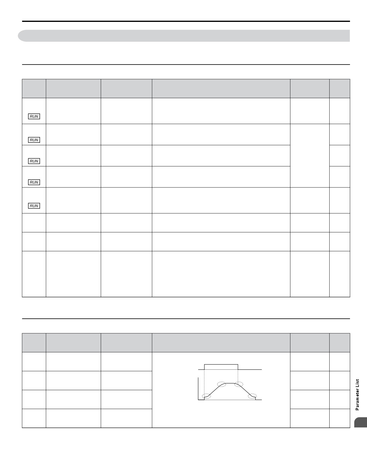
B.3 b: Application
No.
(Addr.
Name
LCD Display
Description
Values
Page
Hex)
Enabled when a multi-function digital input set for “External
Run Source 2
Reference” (H1-oo = 2) closes.
Run Command
0: Operator
b1-16
0: Operator
Default: 0
Selection 2
1: Digital Inputs
123
(01C5)
1: Digital Inputs
Range: 0 to 3
Run Source 2
2: Communication
2: Communication
3: Option PCB
3: Option PCB
0: Disregarded. A new Run command must be issued after
Run Cmd @ Pwr On
b1-17
Run Command at Power
power up.
Default: 1
0: Cycle Ext Run
123
(01C6)
Up
1: Allowed. Drive will run immediately after power up if a Run
Range: 0, 1
1: Accept Ext Run
command is present.
u b2: DC Injection Braking and Short Circuit Braking
No.
(Addr.
Name
LCD Display
Description
Values
Page
Hex)
Sets the frequency at which DC Injection Braking starts when
Default: 0.5 Hz
b2-01
DC Injection Braking
DCInj Start Freq
“Ramp to stop” (b1-03 = 0) is selected.
Min.: 0.0
123
(0189)
Start Frequency
Max.: 10.0
Sets the DC Injection Braking current as a percentage of the
Default: 50%
b2-02
DC Injection Braking
DCInj Current
drive rated current.
Min.: 0
124
(018A)
Current
Max.: 75
Sets DC Injection Braking time at start. Disabled when set to
Default: 0.00 s
b2-03
DC Injection Braking
DCInj Time@Start
0.00 seconds.
Min.: 0.00
124
(018B)
Time at Start
Max.: 10.00
Sets DC Injection Braking time at stop.
Default: 0.50 s
b2-04
DC Injection Braking
DCInj Time@Stop
Min.: 0.00
124
(018C)
Time at Stop
Max.: 10.00
u b3: Speed Search
No.
(Addr
Name
LCD Display
Description
Values
Page
Hex.)
SpdSrch at Start
0: Disabled
b3-01
Speed Search Selection
Default: 0
0: Disabled
1: Enabled
127
(0191)
at Start
Range: 0, 1
1: Enabled
Sets the current level at which the speed is assumed to be
Default: 120%
b3-02
Speed Search
SpdSrch DeactCur
detected and Speed Search is ended. Set as a percentage of the
Min.: 0
127
(0192)
Deactivation Current
drive rated current.
Max.: 200
Sets output frequency reduction time during Speed Search.
Default: 2.0 s
b3-03
Speed Search
SpdSrch Dec Time
Min.: 0.1
127
(0193)
Deceleration Time
Max.: 10.0
When using an external contactor on the output side, b3-05
Default: 0.2 s
b3-05
Speed Search Delay
Search Delay
delays executing Speed Search after a momentary power loss to
Min.: 0.0
127
(0195)
Time
allow time for the contactor to close.
Max.: 100.0
Sets the current injected to the motor at the beginning of Speed
Default: <1>
b3-06
Output Current 1 during
Srch Im Lvl1
Estimation Speed Search. Set as a coefficient for the motor rated
Min.: 0.0
128
(0196)
Speed Search
current.
Max.: 2.0
Current Control Gain
Sets the proportional gain for the current controller during Speed
Default: 0.50
b3-08
during Speed Search
Search.
Srch ACR P Gain
Min.: 0.00
128
(0198)
(Speed Estimation
Max.: 6.00
Type)
Sets the gain which is applied to the speed detected by Speed
Default: 1.05
b3-10
Speed Search Detection
Estimation Speed Search before the motor is reaccelerated.
Srch Detect Comp
Min.: 1.00
128
(019A)
Compensation Gain
Increase this setting if ov occurs when performing Speed Search
Max.: 1.20
after a relatively long period of baseblock.
Bidir Search Sel
0: Disabled (uses the direction of the frequency reference)
b3-14
Bi-Directional Speed
Default: 0
0: Disabled
1: Enabled (drive detects which way the motor is rotating)
128
(019E)
Search Selection
Range: 0, 1
1: Enabled
B
321
B.3 b: Application
No.
(Addr
Name
LCD Display
Description
Values
Page
Hex.)
Sets the Speed Search restart current level as a percentage of the
Default: 150%
b3-17
Speed Search Restart
SrchRestart Lvl
drive rated current.
Min.: 0
128
(01F0)
Current Level
Max.: 200
Sets the time to detect Speed Search restart.
Default: 0.10 s
b3-18
Speed Search Restart
SrchRestart Time
Min.: 0.00
128
(01F1)
Detection Time
Max.: 1.00
Sets the number of times the drive can attempt to restart when
Default: 3
b3-19
Number of Speed
Num of SrchRestr
performing Speed Search.
Min.: 0
129
(01F2)
Search Restarts
Max.: 10
SpdSrch Method
0: Current Detection
b3-24
Speed Search Method
Default: 0
0: CurrentDetection
1: Speed Estimation
129
(01C0)
Selection
Range: 0, 1
1: Speed Estimation
Sets the time the drive must wait between each Speed Search
Default: 0.5 s
b3-25
Speed Search Wait Time
SpdSrch WaitTime
restart attempt.
Min.: 0.0
129
(01C8)
Max.: 30.0
<1> Default setting is dependent on parameter o2-04, Drive Model Selection.
u b4: Timer Function
No.
(Addr.
Name
LCD Display
Description
Values
Page
Hex)
Sets the on-delay and off-delay times for a digital timer output
Default: 0.0 s
b4-01
Timer Function On-
Delay-ON Timer
(H2-oo=12).
Min.: 0.0
129
(01A3)
Delay Time
The output is triggered by a digital input programmed to
Max.: 300.0
H1-oo=18).
Default: 0.0 s
b4-02
Timer Function Off-
Delay-OFF Timer
Min.: 0.0
129
(01A4)
Delay Time
Max.: 300.0
u b5: PID Control
No.
(Addr.
Name
LCD Display
Description
Values
Page
Hex)
PID Mode
0: Disabled
b5-01
Default: 1
PID Function Setting
0: Disabled
1: Enabled (PID output becomes output frequency reference,
133
(01A5)
Range: 0, 1
1: Enabled D=Fdbk
deviation D controlled)
b5-02
Sets the proportional gain of the PID controller.
Default: 2.00
Proportional Gain
(01A6)
PID Gain
Min.: 0.00
133
Setting (P)
Max.: 25.00
b5-03
Sets the integral time for the PID controller.
Default: 3.0 s
(01A7)
Integral Time Setting (I)
PID I Time
Min.: 0.0
133
Max.: 360.0
b5-04
Sets the maximum output possible from the integrator as a
Default: 100.0%
(01A8)
Integral Limit Setting
PID I Limit
percentage of the maximum output frequency.
Min.: 0.0
134
Max.: 100.0
b5-05
Sets D control derivative time.
Default: 0.00 s
-
(01A9)
Derivative Time (D)
PID D Time
Min.: 0.00
134
Max.: 10.00
b5-06
Sets the maximum output possible from the entire PID controller
Default: 100.0%
(01AA)
PID Output Limit
PID Limit
as a percentage of the maximum output frequency.
Min.: 0.0
134
Max.: 100.0
b5-07
Applies an offset to the PID controller output. Set as a
Default: 0.0%
(01AB)
PID Offset Adjustment
PID Offset
percentage of the maximum output frequency.
Min.: -100.0
134
Max.: 100.0
b5-08
Sets a low pass filter time constant on the output of the PID
Default: 0.00 s
(01AC)
PID Primary Delay
controller.
PID Delay Time
Min.: 0.00
134
Time Constant
Max.: 10.00
322
B.3 b: Application
No.
(Addr.
Name
LCD Display
Description
Values
Page
Hex)
Output Level Sel
0: Direct acting
b5-09
PID Output Level
Default: 0
0: Direct Acting
1: Inverse acting
133
(01AD)
Selection
Range: 0, 1
1: Inverse Acting
b5-10
Sets the gain applied to the PID output.
Default: 1.00
(01AE)
PID Output Gain Setting
Output Gain
Min.: 0.00
134
Max.: 25.00
0: Negative PID output triggers zero limit.
Output Rev Sel
1: Rotation direction reverses with negative PID output.
b5-11
PID Output Reverse
Default: 0
0: 0 limit
134
(01AF)
Selection
Note:
When using setting 1, make sure reverse
Range: 0, 1
1: Reverse
operation is permitted by b1-04.
Performs a 4 to 20 mA wire break detection on the analog input
Fdbk 4-20mA Det
that is programmed for PID feedback.
0: Disabled
b5-12
Feedback Loss 4 to 20
0: Disabled
Default: 2
1: Alarm only
135
(01B0)
mA Detection Selection
1: Alarm only
Range: 0 to 3
2: Fault
2: Fault
3: Run At b5-13
3: Run at b5-13
Sets the speed at which the drive will run if a 4 to 20 mA wire
Default: 0.0 Hz
b5-13
Feedback Loss Goto
FdbkLossGotoFreq
break is detected on the PID Feedback and when b5-12 is set to
Min.: 0.0
136
(01B1)
Frequency
3 (Run at b5-13).
Max.: 400.0
Detects loss of prime in the pump when a wire break condition
has occurred.
b5-14
When the measured quantity determined by P1-18 (output
Default: 0.0 A
Feedback Loss of Prime
current, kilowatts, or power) drops below this level for the time
<1>
(01B2)
FdbkLoss LOP Lvl
136
Level
set in P1-20 and the output frequency is at the level set in b5-13,
Min.: 0.0
a “Loss of Prime” condition occurs.
Max.: 1000.0
The drive responds to the “Loss of Prime” condition depending
on the setting of P1-22, Loss of Prime Selection.
When b5-12 = 3 and the Feedback signal is lost, the drive will
b5-15
run at the b5-13 speed for the b5-15 time, after which the drive
Default: 0 s
(01B3)
Feedback Loss Go To
FdbkLossGotoTimO
will fault on Feedback Loss (FDBKL).
Min.: 0
136
Frequency Time Out
Timeout is disabled when set to 0sec and the drive will run
Max.: 6000
indefinitely at b5-13.
b5-16
When an AUTO Run command is initiated, the drive will not
Default: 0.0 s
Feedback Loss Start
(01B4)
FdbkLossStartDly
fault on Feedback Loss (FDBKL) or use the Feedback Loss
Min.: 0.0
136
Delay
GoTo Frequency (b5-13) until the b5-16 time has expired.
Max.: 120.0
Sets the acceleration and deceleration time to PID setpoint.
Default: 0 s
b5-17
PID Accel/Decel Time
PID Acc/Dec Time
Min.: 0
137
(01B5)
Max.: 255
b5-32
Default: 0.0 Hz
(01EE)
When set to a value greater than zero, the PID Integrator is
Integrator Ramp Limit
IntegratrRampLim
Min.: 0.0
137
forced to be within +/- this amount of the soft starter output.
Max.: 10.0
b5-34
Sets the minimum output possible from the PID controller as a
Default: 0.00%
PID Output Lower
(019F)
PID Out Low Lim
percentage of the maximum output frequency.
Min.: -100.00
137
Limit
Max.: 100.00
Limits the PID control input (deviation signal) as a percentage
Default:
b5-35
of the maximum output frequency. Acts as a bipolar limit.
1000.0%
(01A0)
PID Input Limit
PID Input Limit
137
Min.: 0.0
Max.: 1000.0
Determines the number of digits in the user-defined display for
PID UsrDspDigits
the PID parameters and monitors (Q1-oo, U5-99, etc).
0: No Dec (XXXXX)
b5-39
PID System Units
0: No decimal place
Default: 1
1: 1 Dec (XXX.X)
137
(01FF)
Display Digits
1: One decimal place
Range: 0 to 3
2: 2 Dec (XX.XX)
2: Two decimal places
3: 3 Dec (XX.XXX)
3: Three decimal places
0: Display the frequency reference (U1-01) after PID
Frequency Reference
Fref Mon Sel@PID
b5-40
compensation has been added.
Default: 0
Monitor Content during
0: Fref Mon w PID
138
(017F)
1: Display the frequency reference (U1-01) before PID
Range: 0, 1
PID
1: Fref Mon w/o PID
compensation has been added.
Reverse Operation
Output Rev Sel2
0: Zero limit when PID output is a negative value.
b5-47
Default: 1
Selection 2 by PID
0: 0 Limit
1: Reverse operation when PID output is a negative value
138
(017D)
Range: 0, 1
B
Output
1: Reverse
(Zero limit if the reverse operation is prohibited by b1-04).
<1> Unit text is set by P1-18, Prime Loss Detection Method.
323
B.3 b: Application
u b6: Dwell Function
No.
(Addr.
Name
Description
Values
Page
Hex)
Parameters b6-01 and b6-02 set the frequency to hold and the
Default: 0.0 Hz
b6-01
Dwell Reference at Start
Dwell Ref @Start
time to maintain that frequency at start.
Min.: 0.0
138
(01B6)
Max.: 400.0
Default: 0.0 s
b6-02
Dwell Time at Start
Dwell Time @Start
Min.: 0.0
138
(01B7)
Max.: 10.0
Parameters b6-03 and b6-04 set the frequency to hold and the
Default: 0.0 Hz
b6-03
Dwell Reference at Stop
Dwell Ref @Stop
time to maintain that frequency at stop.
Min.: 0.0
139
(01B8)
Max.: 400.0
Default: 0.0 s
b6-04
Dwell Time at Stop
Dwell Time @Stop
Min.: 0.0
139
(01B9)
Max.: 10.0
324
B.4 C: Tuning
B.4
C: Tuning
C parameters are used to adjust the acceleration and deceleration times, S-curves, slip and torque compensation functions and
carrier frequency selections.
u C1: Acceleration and Deceleration Times
No.
(Addr.
Name
LCD Display
Description
Values
Page
Hex)
Sets the time to accelerate from 0 to maximum frequency.
Default: 20.0 s
C1-01
Min.: 0.0
(0200)
Acceleration Time 1
Accel Time 1
140
Max.: 6000.0
<1>
C1-02
Sets the time to decelerate from maximum frequency to 0.
(0201)
Deceleration Time 1
Decel Time 1
140
Default: 10.0 s
C1-03
Sets the time to accelerate from 0 to maximum frequency.
Min.: 0.0
(0202)
Acceleration Time 2
Accel Time 2
140
Max.: 6000.0
<1>
C1-04
Sets the time to decelerate from maximum frequency to 0.
(0203)
Deceleration Time 2
Decel Time 2
140
Sets the time for the Fast Stop function.
Default: 10.0 s
C1-09
Min.: 0.0
(0208)
Fast Stop Time
Fast Stop Time
140
Max.: 6000.0
<1>
Acc/Dec Units
0: 0.01 s (0.00 to 600.00 s)
C1-10
Accel/Decel Time
Default: 1
0: 0.01 Seconds
1: 0.1 s (0.0 to 6000.0 s)
141
(0209)
Setting Units
Range: 0, 1
1: 0.1 Seconds
Sets the frequency to switch between accel/decel time settings.
Default: 0.0 Hz
C1-11
Accel/Decel Time
Acc/Dec SW Freq
Min.: 0.0
141
(020A)
Switching Frequency
Max.: 400.0
Sets the base frequency used to calculate acceleration and
deceleration times.
When set to 0.0 Hz, the drive calculates the time required to
Default: 0.0 Hz
C1-14
Accel/Decel Rate
accelerate from 0 Hz to E1-04, and decelerate from E1-04 down
Acc/DecRate Freq
Min.: 0.0
141
(0264)
Frequency
to 0 Hz (conventional setting).
Max.: 400.0
When set to any other value above 0.0 Hz, the drive calculates
the time required to accelerate from 0 Hz to C1-14, and to
decelerate from C1-14 down to 0 Hz.
<1> Setting range value is dependent on parameter C1-10, Accel/Decel Time Setting Units. When C1-10 = 0 (units of 0.01 seconds), the setting range
becomes 0.00 to 600.00 seconds.
u C2: S-Curve Characteristics
No.
(Addr.
Name
LCD Display
Description
Values
Page
Hex)
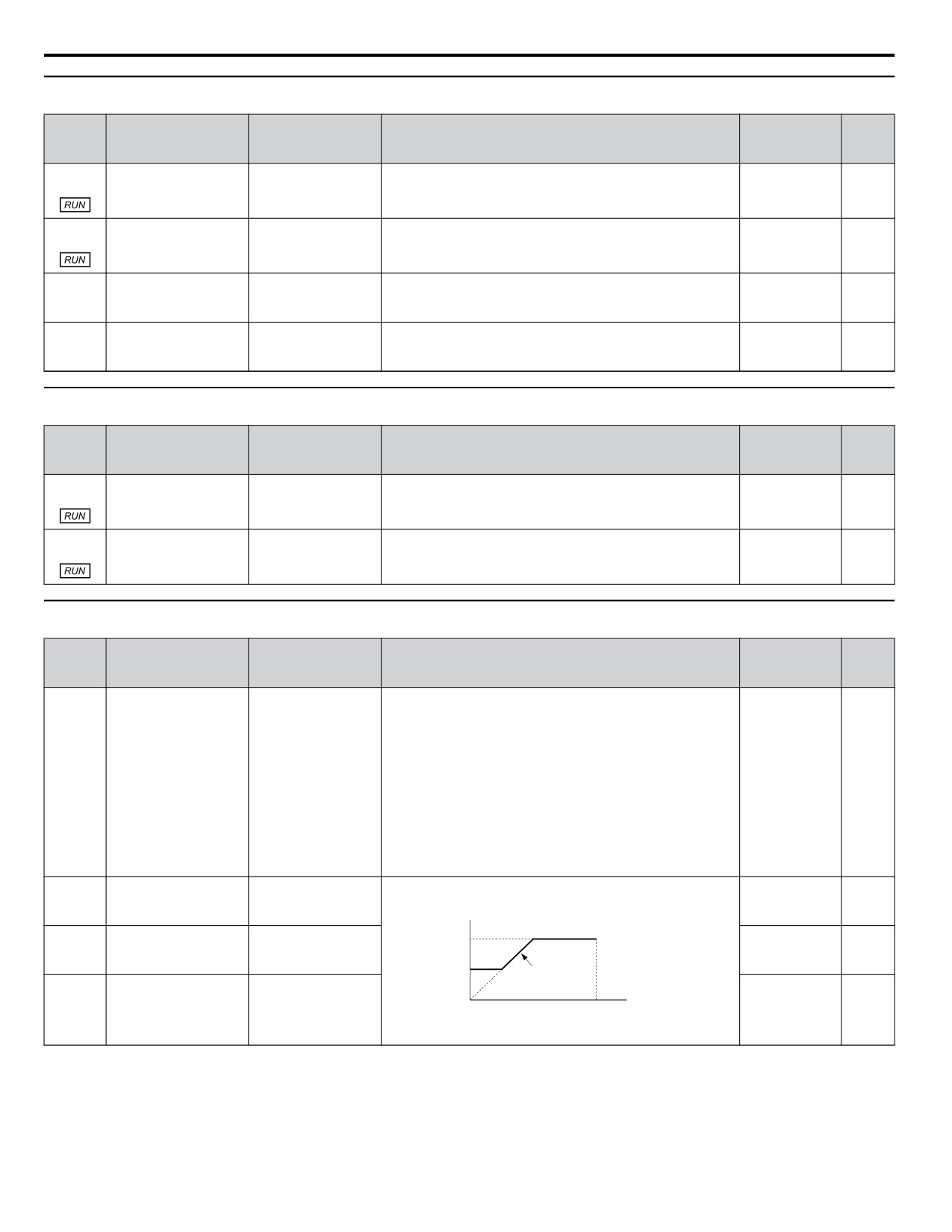
The S-curve can be controlled at the four points shown below.
Default: 0.20 s
C2-01
S-Curve Characteristic
SCrv Acc @ Start
Min.: 0.00
143
(020B)
at Accel Start
ON
OFF
Max.: 10.00
Run Command
Output Frequency
Default: 0.20 s
C2-02
S-Curve Characteristic
C2-02
C2-03
SCrv Acc @ End
Min.: 0.00
143
(020C)
at Accel End
Max.: 10.00
C2-01
C2-04
Default: 0.20 s
C2-03
S-Curve Characteristic
SCrv Dec @ Start
Time
Min.: 0.00
143
(020D)
at Decel Start
Max.: 10.00
Default: 0.00 s
C2-04
S-Curve Characteristic
SCrv Dec @ End
Min.: 0.00
143
(020E)
at Decel End
Max.: 10.00
B
325
B.4 C: Tuning
u C3: Slip Compensation
No.
(Addr.
Name
LCD Display
Description
Values
Page
Hex)
C3-01
Sets the gain for the motor slip compensation function used for
Default: 0.0
(020F)
Slip Compensation Gain
Slip Comp
motor 1.
Min.: 0.0
143
Max.: 2.5
C3-02
Adjusts the slip compensation function delay time used for
Default: 2000 ms
(0210)
Slip Compensation
motor 1.
Slip Comp Time
Min.: 0
143
Primary Delay Time
Max.: 10000
Sets an upper limit for the slip compensation function as a
Default: 200%
C3-03
Slip Compensation
Slip Comp Limit
percentage of motor rated slip for motor 1 (E2-02).
Min.: 0
143
(0211)
Limit
Max.: 250
Slip Compensation
Slip Comp Regen
0: Disabled.
C3-04
Default: 0
Selection during
0: Disabled
1: Enabled above 6 Hz
144
(0212)
Range: 0, 1
Regeneration
1: Above 6 Hz
u C4: Torque Compensation
No.
(Addr.
Name
LCD Display
Description
Values
Page
Hex)
C4-01
Sets the gain for the automatic torque (voltage) boost function
Default: 1.00
Torque Compensation
(0215)
Torq Comp Gain
and helps to produce better starting torque. Used for motor 1.
Min.: 0.00
144
Gain
Max.: 2.50
C4-02
Sets the torque compensation filter time.
Default: 200 ms
(0216)
Torque Compensation
Torq Comp Time
Min.: 0
144
Primary Delay Time 1
Max.: 60000
u C6: Carrier Frequency
No.
(Addr.
Name
LCD Display
Description
Values
Page
Hex)
CarrierFreq Sel
1: 2.0 kHz
1: 2.0 kHz
2: 5.0 kHz (4.0 kHz)
2: 5.0 kHz
3: 8.0 kHz (6.0 kHz)
3: 8.0 kHz
4: 10.0 kHz (8.0 kHz)
4: 10.0 kHz
5: 12.5 kHz (10.0 kHz)
5: 12.5 kHz
6: 15.0 kHz (12.0 kHz)
C6-02
Carrier Frequency
Default: 7
6: 15.0 kHz
7: Swing PWM1 (Audible sound 1)
145
(0224)
Selection
Range: 1 to B; F
7: Swing PWM1
8: Swing PWM2 (Audible sound 2)
8: Swing PWM2
9: Swing PWM3 (Audible sound 3)
9: Swing PWM3
A: Swing PWM4 (Audible sound 4)
A: Swing PWM4
B: Leakage Current Rejection PWM
B: LeakageRejection
C to E: No setting possible
F: Program
F: User-defined (determined by C6-03 through C6-05)
Determines the upper and lower limits for the carrier frequency.
Default: 2.0 kHz
C6-03
Carrier Frequency
CarrierFreq Max
Min.: 1.0
146
(0225)
Upper Limit
Carrier Frequency
Max.: 15.0
C6-03
Default: 2.0 kHz
C6-04
Carrier Frequency
CarrierFreq Min
Min.: 1.0
146
(0226)
Lower Limit
Max.: 15.0
C6-04
Output Frequency
× (C6-05) × K
Output
Default: 0
C6-05
Carrier Frequency
Frequency
CarrierFreq Gain
E1-04
Min.: 0
146
(0227)
Proportional Gain
Max Output
Max.: 99
Frequency
326
B.5 d: References
B.5
d: References
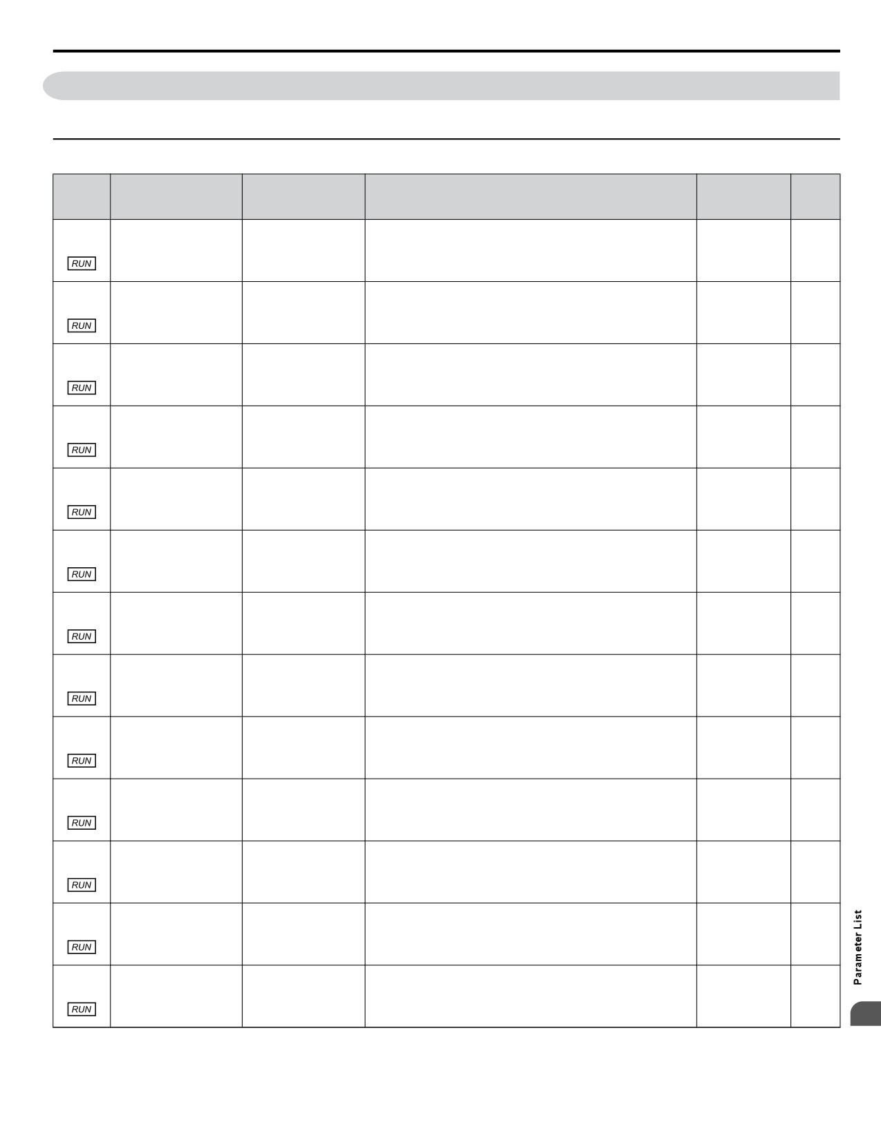
Reference parameters are used to set the various frequency reference values during operation.
u d1: Frequency Reference
No.
(Addr.
Name
LCD Display
Description
Values
Page
Hex)
Sets the frequency reference for the drive. Setting units are
Default: 0.00 Hz
d1-01
determined by parameter o1-03.
Min.: 0.00
(0280)
Frequency Reference 1
Reference 1
147
Max.: 400.00
<1>
Default: 0.00 Hz
d1-02
Frequency reference when digital input "Multi-Step Speed
Min.: 0.00
(0281)
Frequency Reference 2
Reference 2
147
Reference 1" (H1-oo = 3) is on.
Max.: 400.00
<1>
Default: 0.00 Hz
d1-03
Frequency reference when digital input "Multi-Step Speed
Min.: 0.00
(0282)
Frequency Reference 3
Reference 3
147
Reference 2” (H1-oo = 4) is on.
Max.: 400.00
<1>
Default: 0.00 Hz
d1-04
Frequency reference when digital inputs "Multi-Step Speed
Min.: 0.00
(0283)
Frequency Reference 4
Reference 4
147
Reference 1, 2" (H1-oo = 3 and 4) are on.
Max.: 400.00
<1>
Default: 0.00 Hz
d1-05
Frequency reference when digital input "Multi-Step Speed
Min.: 0.00
(0284)
Frequency Reference 5
Reference 5
147
Reference 3" (H1-oo = 5) is on.
Max.: 400.00
<1>
Default: 0.00 Hz
d1-06
Frequency reference when digital inputs "Multi-Step Speed
Min.: 0.00
(0285)
Frequency Reference 6
Reference 6
147
Reference 1, 3 " (H1-oo = 3 and 5) are on.
Max.: 400.00
<1>
Default: 0.00 Hz
d1-07
Frequency reference when digital inputs "Multi-Step Speed
Min.: 0.00
(0286)
Frequency Reference 7
Reference 7
147
Reference 2, 3" (H1-oo = 4 and 5) are on.
Max.: 400.00
<1>
Default: 0.00 Hz
d1-08
Frequency reference when multi-function input "Multi-Step
Min.: 0.00
(0287)
Frequency Reference 8
Reference 8
147
speed reference 1, 2, 3" (H1-oo = 3, 4, 5) are on.
Max.: 400.00
<1>
Default: 0.00 Hz
d1-09
Frequency reference when multi-function input "Multi-Step
Min.: 0.00
(0288)
Frequency Reference 9
Reference 9
147
Speed Reference 4" (H1-oo= 32) is on.
Max.: 400.00
<1>
Default: 0.00 Hz
d1-10
Frequency reference when digital input "Multi-Step Speed
Min.: 0.00
(028B)
Frequency Reference 10
Reference 10
147
Reference 1, 4" (H1-oo = 3 and 32) are on.
Max.: 400.00
<1>
Default: 0.00 Hz
d1-11
Frequency reference when digital inputs "Multi-Step Speed
Min.: 0.00
(028C)
Frequency Reference 11
Reference 11
147
Reference 2, 4" (H1-oo = 4 and 32) are on.
Max.: 400.00
<1>
Default: 0.00 Hz
d1-12
Frequency reference when digital inputs "Multi-Step Speed
Min.: 0.00
(028D)
Frequency Reference 12
Reference 12
147
Reference 1, 2, 4" (H1-oo = 3, 4, 32) are on.
Max.: 400.00
<1>
Default: 0.00 Hz
d1-13
Frequency reference when digital inputs "Multi-Step Speed
Min.: 0.00
(028E)
Frequency Reference 13
Reference 13
147
Reference 3, 4" (H1-oo = 5 and 32) are on.
Max.: 400.00
<1>
B
327
B.5 d: References
No.
(Addr.
Name
LCD Display
Description
Values
Page
Hex)
Default: 0.00 Hz
d1-14
Frequency reference when digital inputs "Multi-Step Speed
Min.: 0.00
(028F)
Frequency Reference 14
Reference 14
147
Reference 1, 3, 4" (H1-oo = 3, 5, 32) are on.
Max.: 400.00
<1>
Default: 0.00 Hz
d1-15
Frequency reference when digital inputs "Multi-Step Speed
Min.: 0.00
(0290)
Frequency Reference 15
Reference 15
147
Reference 2, 3, 4" (H1-oo = 4, 5, 32) are on.
Max.: 400.00
<1>
Default: 0.00 Hz
d1-16
Frequency reference when digital inputs "Multi-Step Speed
Min.: 0.00
(0291)
Frequency Reference 16
Reference 16
147
Reference 1, 2, 3, 4" (H1-oo = 3, 4, 5, 32) are on.
Max.: 400.00
<1>
Frequency reference when digital inputs "Jog Frequency
Default: 6.00 Hz
d1-17
Jog Frequency
Reference", "Forward Jog", or "Reverse Jog." are on. "Jog
Min.: 0.00
(0292)
Jog Reference
147
Reference
Frequency Reference" has priority over "Multi-Step Speed
Max.: 400.00
Reference 1 to 16”.
<1>
<1> Range upper limit is determined by parameters d2-01, Frequency Reference Upper Limit, and E1-04, Maximum Output Frequency.
u d2: Frequency Upper/Lower Limits
No.
(Addr.
Name
LCD Display
Description
Setting
Page
Hex.)
Sets the frequency reference upper limit as a percentage of the
Default: 100.0%
d2-01
Frequency Reference
Ref Upper Limit
maximum output frequency.
Min.: 0.0
148
(0289)
Upper Limit
Max.: 110.0
Sets the frequency reference lower limit as a percentage of the
Default: 0.0%
d2-02
Frequency Reference
Ref Lower Limit
maximum output frequency.
Min.: 0.0
148
(028A)
Lower Limit
Max.: 110.0
Sets the lower limit for frequency references from analog inputs
Default: 0.0%
d2-03
Master Speed Reference
Ref1 Lower Limit
as a percentage of the maximum output frequency.
Min.: 0.0
149
(0293)
Lower Limit
Max.: 110.0
u d3: Jump Frequency
No.
(Addr.
Name
LCD Display
Description
Values
Page
Hex)
Eliminates problems with resonant vibration of the motor/
Default: 0.0 Hz
d3-01
Jump Frequency 1
Jump Freq 1
machine by avoiding continuous operation in predefined
Min.: 0.0
149
(0294)
frequency ranges. The drive accelerates and decelerates the
Max.: 400.0
motor through the prohibited frequency ranges.
Default: 0.0 Hz
d3-02
Parameters must be set so that d3-01 ≥ d3-02 ≥ d3-03.
Jump Frequency 2
Jump Freq 2
Min.: 0.0
149
(0295)
Setting this parameter to 0.0 disables the function.
Max.: 400.0
Default: 0.0 Hz
d3-03
Jump Frequency 3
Jump Freq 3
Min.: 0.0
149
(0296)
Max.: 400.0
Sets the dead-band width around each selected prohibited
Default: 1.0 Hz
d3-04
Jump Frequency Width
Jump Bandwidth
frequency reference point.
Min.: 0.0
149
(0297)
Max.: 20.0
328
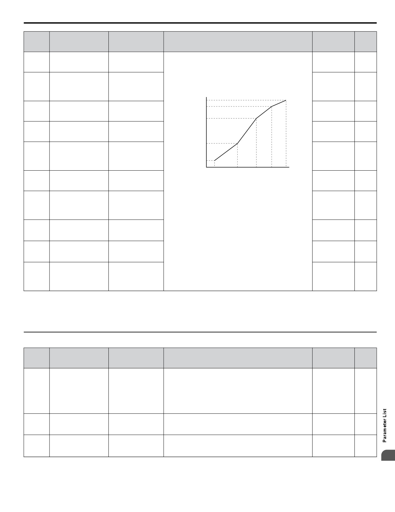
B.5 d: References
u d4: Frequency Reference Hold and Up/Down 2 Function
No.
(Addr.
Name
LCD Display
Description
Values
Page
Hex)
0: Disabled. Drive starts from zero when the power is switched
Fref Hold Sel
d4-01
Frequency Reference
on.
Default: 0
0: Disabled
150
(0298)
Hold Function Selection
1: Enabled. At power up, the drive starts the motor at the Hold
Range: 0, 1
1: Enabled
frequency that was saved.
d4-03
Sets the bias added to the frequency reference when the Up 2
Default: 0.00 Hz
Frequency Reference
(02AA)
Up/Dn 2 Step Lvl
and Down 2 digital inputs are enabled (H1-oo = 75, 76).
Min.: 0.00
152
Bias Step (Up/Down 2)
Max.: 99.99
0: Bias value is held if no input Up 2 or Down 2 is active.
d4-05
Frequency Reference
Up/Dn 2 Bias Sel
1: When the Up 2 reference and Down 2 reference are both on
Default: 0
(02AC)
Bias Operation Mode
0: Hold Bias Value
153
or both off, the applied bias becomes 0. The specified accel/
Range: 0, 1
Selection (Up/Down 2)
1: Reset Bias Value
decel times are used for acceleration or deceleration.
The Up/Down 2 bias value is saved in d4-06 when the frequency
Default: 0.0%
d4-06
Frequency Reference
Up/Dn 2 Bias Lvl
reference is not input by the digital operator. Set as a percentage
Min.: -99.9
153
(02AD)
Bias (Up/Down 2)
of the maximum output frequency.
Max.: 100.0
Limits how much the frequency reference is allowed to change
while an input terminal set for Up 2 or Down 2 is enabled. If the
d4-07
Analog Frequency
Default: 1.0%
frequency reference changes for more than the set value, then
(02AE)
Reference Fluctuation
Up/Dn 2 FluctLim
Min.: 0.1
154
the bias value is held and the drive accelerates or decelerates to
Limit (Up/Down 2)
Max.: 100.0
the frequency reference. Set as a percentage of the maximum
output frequency.
d4-08
Frequency Reference
Sets the upper limit for the bias and the value that can be saved
Default: 100.0%
(2AF)
Bias Upper Limit (Up/
Up/Dn 2 UpperLim
in d4-06. Set as a percentage of the maximum output frequency.
Min.: 0.0
154
Down 2)
Max.: 100.0
d4-09
Frequency Reference
Sets the lower limit for the bias and the value that can be saved
Default: 0.0%
(02B0)
Bias Lower Limit (Up/
Up/Dn 2 LowerLim
in d4-06. Set as a percentage of the maximum output frequency.
Min.: -99.9
154
Down 2)
Max.: 0.0
Up/Down Frequency
Up/Dn LowLim Sel
0: The lower limit is determined by d2-02 or an analog input.
d4-10
Default: 0
Reference Limit
0: D2-02 or Analog
1: The lower limit is determined by d2-02.
154
(02B6)
Range: 0, 1
Selection
1: D2-02 Only
B
329

B.6 E: Motor Parameters
B.6
E: Motor Parameters
u E1: V/f Pattern
No.
(Addr.
Name
LCD Display
Description
Values
Page
Hex)
This parameter must be set to the power supply voltage.
WARNING! Electrical Shock Hazard. Drive input voltage
Default: 230 V
<1>
E1-01
(not motor voltage) must be set in E1-01 for the protective
Input Voltage Setting
Input Voltage
155
(0300)
features of the drive to function properly. Failure to do so
Min.: 155
may result in equipment damage and/or death or personal
Max.: 255 <1>
injury.
V/F Selection
0: 50 Hz, Constant torque 1
0: 50 Hz
1: 60 Hz, Constant torque 2
1: 60 Hz Saturation
2: 60 Hz, Constant torque 3 (50 Hz base)
2: 60 Hz Saturation
3: 72 Hz, Constant torque 4 (60 Hz base)
3: 72 Hz
4: 50 Hz, Variable torque 1
4: 50 Hz VT1
5: 50 Hz, Variable torque 2
5: 50 Hz VT2
6: 60 Hz, Variable torque 3
6: 60 Hz VT1
7: 60 Hz, Variable torque 4
Default: F <2>
E1-03
V/f Pattern Selection
7: 60 Hz VT2
8: 50 Hz, High starting torque 1
Range: 0 to 9;
155
(0302)
8: 50 Hz HST1
9: 50 Hz, High starting torque 2
A to FF
9: 50 Hz HST2
A: 60 Hz, High starting torque 3
A: 60 Hz HST1
B: 60 Hz, High starting torque 4
B: 60 Hz HST2
C: 90 Hz (60 Hz base)
C: 90 Hz
D: 120 Hz (60 Hz base)
D: 120 Hz
E: 180 Hz (60 Hz base)
E: 180 Hz
F: Custom V/f, E1-04 through E1-13 settings define the V/f
F: Custom V/F
pattern
330
B.6 E: Motor Parameters
No.
(Addr.
Name
LCD Display
Description
Values
Page
Hex)
These parameters are only applicable when E1-03 is set to F.
Default: 60.0 Hz
E1-04
Maximum Output
Max Frequency
To set linear V/f characteristics, set the same values for E1-07
Min.: 40.0
158
(0303)
Frequency
and E1-09.
Max.: 400.0
In this case, the setting for E1-08 will be disregarded. Ensure
Default: 230 V
that the four frequencies are set according to these rules:
E1-05
<1>
Maximum Voltage
Max Voltage
E1-09 ≤ E1-07 < E1-06 ≤ E1-11 ≤ E1-04
158
(0304)
Min.: 0.0
Output Voltage (V)
Max.: 255.0 <1>
E1-05
E1-12
Default: 60.0 Hz
E1-06
Base Frequency
Base Frequency
Min.: 0.0
158
(0305)
E1-13
Max.: E1-04
Default: 3.0 Hz
E1-07
Middle Output
Mid Frequency A
Min.: 0.0
158
(0306)
Frequency
Max.: E1-04
E1-08
Default: 18.4 V
E1-08
Middle Output
<1>
Mid Voltage A
158
(0307)
Frequency Voltage
E1-10
Min.: 0.0
Max.: 255.0 <1>
E1-09
E1-07
E1-06 E1-11 E1-04
Default: 1.5 Hz
E1-09
Minimum Output
Frequency (Hz)
Min Frequency
Min.: 0.0
158
(0308)
Frequency
Max.: E1-04
Default: 13.8 V
E1-10
Minimum Output
<1>
Min Voltage
158
(0309)
Frequency Voltage
Min.: 0.0
Max.: 255.0 <1>
E1-11
Default: 0.0 Hz
Middle Output
(030A)
Mid Frequency B
Min.: 0.0
158
<4>
Frequency 2
Max.: E1-04
E1-12
Default: 0.0 V
Middle Output
(030B)
Mid Voltage B
Min.: 0.0
158
<4>
Frequency Voltage 2
Max.: 255.0 <1>
Default: 0.0 V
E1-13
<3>
Base Voltage
Base Voltage
158
(030C)
Min.: 0.0
Max.: 255.0 <1>
<1> Values shown are specific to 200 V class drives. Double the value for 400 V class drives.
<2> Parameter setting value is not reset to the default value when the drive is initialized.
<3> When Auto-Tuning is performed, E1-13 and E1-05 will be set to the same value.
<4> Parameter ignored when E1-11 (Motor 1 Mid Output Frequency 2) and E1-12 (Motor 1 Mid Output Frequency Voltage 2) are set to 0.0.
u E2: Motor 1 Parameters
No.
(Addr.
Name
LCD Display
Description
Values
Page
Hex)
Sets the motor nameplate full load current in amps.
Default: <1>
Automatically set during Auto-Tuning.
Min.: 10% of
drive rated
E2-01
Motor Rated Current
Motor Rated FLA
current
149
(30E)
Max.: 200% of
drive rated
current <2>
Sets the motor rated slip. Automatically set during Auto-Tuning.
Default: <1>
E2-02
Motor Rated Slip
Motor Rated Slip
Min.: 0.00 Hz
159
(030F)
Max.: 20.00 Hz
Sets the no-load current for the motor. Automatically set during
<1>
Default:
E2-03
Motor No-Load Current
No-Load Current
Auto-Tuning.
Min.: 0 A
159
(0310)
Max.: E2-01 <2>
B
331
B.6 E: Motor Parameters
No.
(Addr.
Name
LCD Display
Description
Values
Page
Hex)
Sets the number of motor poles. Automatically set during
Default: 2
E2-04
Number of Motor Poles
Number of Poles
Auto-Tuning.
Min.: 2
159
(0311)
Max.: 48
Sets the phase-to-phase motor resistance. Automatically set
Default: <1>
E2-05
Motor Line-to-Line
Term Resistance
during Auto-Tuning.
Min.: 0.000 Ω
159
(0312)
Resistance
Max.: 65.000 Ω
Sets the voltage drop due to motor leakage inductance as a
Default: <1>
E2-06
Motor Leakage
Leak Inductance
percentage of motor rated voltage. Automatically set during
Min.: 0.0%
160
(0313)
Inductance
Auto-Tuning.
Max.: 40.0%
Sets the motor iron loss.
Default: <1>
E2-10
Motor Iron Loss for
Motor Iron Loss
Min.: 0 W
160
(0317)
Torque Compensation
Max.: 65535 W
Sets the motor rated power in kilowatts (1 HP = 0.746 kW).
Default: <1>
E2-11
Automatically set during Auto-Tuning.
Min.: 0.00 kW
Motor Rated Power
Mtr Rated Power
160
(0318)
Max.: 650.00
kW
<1> Default setting is dependent on parameter o2-04, Drive Model Selection.
<2> Display is in the following units:
BV0006 to BV0018, 2V0006 to 2V0040, and 4V0002 to 4V0023: 0.01 A units.
2V0056 to 2V0069 and 4V0031 to 4V0038: 0.1 A units.
332
B.7 F: Options
B.7
F: Options
u F6, F7: Communication Option Card
F6 and F7 parameters are used for communication-protocol-specific settings.
No.
(Addr.
Name
LCD Display
Description
Values
Page
Hex)
0: Ramp to stop. Decelerate to stop using the deceleration time
Comm Bus Flt Sel
in C1-02.
0: Ramp to Stop
F6-01
Communications Error
1: Coast to stop.
Default: 1
1: Coast to Stop
161
(03A2)
Operation Selection
2: Fast Stop. Decelerate to stop using the deceleration time in
Range: 0 to 3
2: Fast-Stop
C1-09.
3: Alarm Only
3: Alarm only.
External Fault from
EF0 Detection
0: Always detected.
F6-02
Default: 0
Comm. Option
0: Always Detected
1: Detection during run only.
161
(03A3)
Range: 0, 1
Detection Selection
1: Only During Run
0: Ramp to stop. Decelerate to stop using the deceleration time
EF0 Fault Action
in C1-02.
External Fault from
0: Ramp to Stop
F6-03
1: Coast to stop.
Default: 1
Comm. Option
1: Coast to Stop
161
(03A4)
2: Fast Stop. Decelerate to stop using the deceleration time in
Range: 0 to 3
Operation Selection
2: Fast-Stop
C1-09.
3: Alarm Only
3: Alarm only.
Sets the delay time for error detection if a bus error occurs.
Default: 2.0 s
F6-04
bUS Error Detection
BUS Err Det Time
Min.: 0.0
161
(03A5)
Time
Max.: 5.0
Multi-Step Speed
0: Multi-step reference disabled
Fref PrioritySel
F6-07
Enable/Disable
1: Multi-step reference enabled
Default: 0
0: Net/Com REF
162
(03A8)
Selection when NefRef/
Range: 0, 1
1: MultiStep Speed
ComRef is Selected
0: Reset all communication-related parameters (F6-oo) when
F6-08
Com Prm Init Sel
Reset Communication
the drive is initialized using A1-03.
Default: 0
(036A)
0: Init Com Prms
162
<1>
Parameters
1: Communication-related parameters (F6-oo) are not reset
Range: 0, 1
1: No Init Com Prms
when the drive is initialized using A1-03.
Sets the node address.
Default: 0
F6-30
PROFIBUS-DP Node
PB Node Address
Min.: 0
162
(03CB)
Address
Max.: 125
PB Clear Select
0: Resets drive operation with a Clear mode command.
F6-31
PROFIBUS-DP Clear
Default: 0
0: Reset to Zero
1: Maintains the previous operation state when Clear mode
162
(03CC)
Mode Selection
Range: 0, 1
1: Hold Prev Value
command is given.
PB Map Select
0: PPO Type
F6-32
PROFIBUS-DP Data
Default: 0
0: PPO Type
1: Conventional
162
(03CD)
Format Selection
Range: 0, 1
1: Conventional
Selects the drive MAC address.
Default: 64
F6-50
DeviceNet MAC
DN MAC Address
Min.: 0
162
(03C1)
Address
Max.: 64
DN Baud Rate
0: 125 kbps
0: 125 kbps
1: 250 kbps
F6-51
DeviceNet
1: 250 kbps
2: 500 kbps
Default: 4
162
(03C2)
Communication Speed
2: 500 kbps
3: Adjustable from network
Range: 0 to 4
3: Set from Network
4: Detect automatically
4: Auto Detect
Sets the format of the data set from the DeviceNet master to the
Default: 21
F6-52
DeviceNet PCA Setting
DN PCA Selection
drive.
Min.: 0
162
(03C3)
Max.: 255
Sets the format of the data set from the drive to the DeviceNet
Default: 71
F6-53
DeviceNet PPA Setting
DN PPA Selection
master.
Min.: 0
162
(03C4)
Max.: 255
DN Idle Flt Det
0: Enabled
F6-54
DeviceNet Idle Mode
Default: 0
0: Stop
1: Disabled, no fault detection
162
(03C5)
Fault Detection
Range: 0, 1
1: Ignore
B
333
B.7 F: Options
No.
(Addr.
Name
LCD Display
Description
Values
Page
Hex)
DN BAUD RATE
Verifies the baud rate running on the network.
MEM
0: 125 kbps
F6-55
DeviceNet Baud Rate
Default: 0
0: 125 kbps
1: 250 kbps
162
(03C6)
Monitor
Range: 0 to 2
1: 250 kbps
2: 500 kbps
2: 500 kbps
Sets the scaling factor for the speed monitor in DeviceNet.
Default: 0
F6-56
DeviceNet Speed
DN Speed Scale
Min.: -15
162
(03D7)
Scaling
Max.: 15
Sets the scaling factor for the output current monitor in
Default: 0
F6-57
DeviceNet Current
DN Current Scale
DeviceNet.
Min.: -15
162
(03D8)
Scaling
Max.: 15
Sets the scaling factor for the torque monitor in DeviceNet.
Default: 0
F6-58
DeviceNet Torque
DN Torque Scale
Min.: -15
162
(03D9)
Scaling
Max.: 15
Sets the scaling factor for the power monitor in DeviceNet.
Default: 0
F6-59
DeviceNet Power
DN Power Scale
Min.: -15
162
(03DA)
Scaling
Max.: 15
Sets the scaling factor for the voltage monitor in DeviceNet.
Default: 0
F6-60
DeviceNet Voltage
DN Voltage Scale
Min.: -15
162
(03DB)
Scaling
Max.: 15
Sets the scaling factor for the time monitor in DeviceNet.
Default: 0
F6-61
DeviceNet Time
DN Time Scale
Min.: -15
162
(03DC)
Scaling
Max.: 15
Sets the heartbeat interval for DeviceNet communications.
Default: 0
F6-62
DeviceNet Heartbeat
DN Heart Beat
Min.: 0
162
(03DD)
Interval
Max.: 10
Saves and monitors settings 0 to 63 of F6-50 (DeviceNet MAC
Default: 63
F6-63
DeviceNet Network
DN MAC ID MEM
Address).
Min.: 0
162
(03DE)
MAC ID
Max.: 63
F6-64 to
Dynamic I/O Assembly Parameters
F6-71
Dynamic I/O Assembly
-
-
-
(03DF to
Parameters
03C8)
F7-01 to
EtherNet/IP and
F7 parameters are reserved for use with SI-EN3/V and
F7-42
Modbus TCP/IP Option
-
SI-EM3/V options. Refer to the respective Option Manuals for
-
-
(03E5 to
Parameters
details.
037E)
<1> Parameter setting value is not reset to the default value when the drive is initialized.
334
B.8 H Parameters: Multi-Function Terminals
B.8
H Parameters: Multi-Function Terminals
H parameters assign functions to the multi-function input and output terminals.
Note:
Cycle power to the drive to enable MEMOBUS/Modbus settings.
u H1: Multi-Function Digital Inputs
No.
(Addr.
Name
LCD Display
Description
Values
Page
Hex)
Assigns a function to the multi-function digital inputs.
Default: 40 (F)
Multi-Function Digital
H1-01
<1>
Input Terminal S1
Term S1 Func Sel
Refer to pages 336 to 339 for descriptions of setting values.
163
(0438)
Min.: 2
Function Selection
Note:
Set unused terminals to F.
Max.: B0
Multi-Function Digital
Assigns a function to the multi-function digital inputs.
Default: F
H1-02
Refer to pages 336 to 339 for descriptions of setting values.
Input Terminal S2
Term S2 Func Sel
Min.: 2
163
(0439)
Function Selection
Max.: B0
Note:
Set unused terminals to F.
Assigns a function to the multi-function digital inputs.
Multi-Function Digital
Default: 26
H1-03
Refer to pages 336 to 339 for descriptions of setting values.
Input Terminal S3
Term S3 Func Sel
Min.: 0
163
(0400)
Function Selection
Note:
Set unused terminals to F.
Max.: B0
Multi-Function Digital
Assigns a function to the multi-function digital inputs.
Default: 14
H1-04
Refer to pages 336 to 339 for descriptions of setting values.
Input Terminal S4
Term S4 Func Sel
Min.: 0
163
(0401)
Function Selection
Max.: B0
Note:
Set unused terminals to F.
Assigns a function to the multi-function digital inputs.
Default: 8D (0)
Multi-Function Digital
H1-05
<1>
Input Terminal S5
Term S5 Func Sel
Refer to pages 336 to 339 for descriptions of setting values.
163
(0402)
Min.: 0
Function Selection
Note:
Set unused terminals to F.
Max.: B0
Assigns a function to the multi-function digital inputs.
Default: 80 (3)
Multi-Function Digital
H1-06
<1>
Input Terminal S6
Term S6 Func Sel
Refer to pages 336 to 339 for descriptions of setting values.
163
(0403)
Min.: 0
Function Selection
Note:
Set unused terminals to F.
Max.: B0
Assigns a function to the multi-function digital inputs.
Default: 81 (4)
Multi-Function Digital
H1-07
<1>
Input Terminal S7
Term S7 Func Sel
Refer to pages 336 to 339 for descriptions of setting values.
163
(0404)
Min.: 0
Function Selection
Note:
Set unused terminals to F.
Max.: B0
H1-21
Sets the amount of time delay applied to the EF1 fault.
Default: 0.00 s
External Fault 1 Delay
(02D7)
EF1 Delay Time
(20 ≤ H1-01 ≤ 2F)
Min.: 0.00
167
Time
Max.: 300.00
H1-22
Sets the amount of time delay applied to the EF2 fault.
Default: 0.00 s
External Fault 2 Delay
(02D8)
EF2 Delay Time
(20 ≤ H1-02 ≤ 2F)
Min.: 0.00
167
Time
Max.: 300.00
H1-23
Sets the amount of time delay applied to the EF3 fault.
Default: 0.00 s
(02D9)
External Fault 3 Delay
(20 ≤ H1-03 ≤ 2F)
EF3 Delay Time
Min.: 0.00
167
Time
Max.: 300.00
H1-24
Sets the amount of time delay applied to the EF4 fault.
Default: 0.00 s
External Fault 4 Delay
(02DA)
EF4 Delay Time
(20 ≤ H1-04 ≤ 2F)
Min.: 0.00
167
Time
Max.: 300.00
H1-25
Sets the amount of time delay applied to the EF5 fault.
Default: 0.00 s
External Fault 5 Delay
(02DB)
EF5 Delay Time
(20 ≤ H1-05 ≤ 2F)
Min.: 0.00
167
Time
Max.: 300.00
H1-26
Sets the amount of time delay applied to the EF6 fault.
Default: 0.00 s
(02DC)
External Fault 6 Delay
(20 ≤ H1-06 ≤ 2F)
EF6 Delay Time
Min.: 0.00
167
Time
Max.: 300.00
H1-27
Sets the amount of time delay applied to the EF7 fault.
Default: 0.00 s
(02DD)
External Fault 7 Delay
(20 ≤ H1-07 ≤ 2F)
EF7 Delay Time
Min.: 0.00
167
Time
Max.: 300.00
<1> Value in parenthesis is the default setting when a 3-Wire initialization is performed (A1-03 = 3330).
B
335
B.8 H Parameters: Multi-Function Terminals
Table B.2 H1 Multi-Function Digital Input Selections
H1-oo
Function
LCD Display
Description
Page
Setting
Closed: Reverse rotation (only if the drive is set up for 3-Wire sequence)
0
3-Wire sequence
3-Wire Control
Terminals S1 and S2 are automatically set up for the Run command and Stop
163
command.
Open: Run command and frequency reference source 1 (determined by b1-01 and
External Reference 1/2
b1-02)
2
External Ref 1/2 Sel
164
Selection
Closed: Run command and frequency reference source 2 (determined by b1-15
and b1-16)
When input terminals are set to Multi-Step Speed References 1 through 3,
Multi-Step Speed
3
Multi-Step Ref 1
switching combinations of those terminals will create a multi-step speed sequence
164
Reference 1
using the frequency references set in d1-01 through d1-08.
When input terminals are set to Multi-Step Speed References 1 through 3,
Multi-Step Speed
4
Multi-Step Ref 2
switching combinations of those terminals will create a multi-step speed sequence
164
Reference 2
using the frequency references set in d1-01 through d1-08.
When input terminals are set to Multi-Step Speed References 1 through 3,
Multi-Step Speed
5
Multi-Step Ref 3
switching combinations of those terminals will create a multi-step speed sequence
164
Reference 3
using the frequency references set in d1-01 through d1-08.
Closed: Jog frequency reference (d1-17) selected. Jog has priority over all other
6
Jog reference selection
Jog Freq Ref
164
reference sources.
Used to switch between accel/decel time 1 (set in C1-01, C1-02) and accel/decel
Accel/decel time
7
Multi-Acc/Dec 1
time 2
164
selection 1
(set in C1-03, C1-04).
Baseblock command
8
Ext BaseBlk N.O.
Closed: No drive output
164
(N.O.)
Baseblock command
9
Ext BaseBlk N.C.
Open: No drive output
164
(N.C.)
Open: Accel/decel is not held
A
Accel/decel ramp hold
Acc/Dec RampHold
Closed: The drive pauses during acceleration or deceleration and maintains the
164
output frequency.
Drive overheat alarm
B
OH2 Alarm Signal
Closed: An oH2 alarm occurs
164
(oH2)
Analog terminal input
Open: Function assigned by H3-14 is disabled.
C
Term A2 Enable
165
selection
Closed: Function assigned by H3-14 is enabled.
Select this setting when using the terminal in a pass-through mode. The terminal
F
Through mode
Term Not Used
does not trigger a drive function but can be used as digital input for the controller
165
the drive is connected to.
The drive accelerates when the Up command terminal closes, and decelerates when
the Down command closes. When both terminals are closed or both are open, the
10
Up command
Up Command 1
165
drive holds the frequency reference. The Up and Down commands must always
be used in conjunction with one another.
The drive accelerates when the Up command terminal closes, and decelerates when
the Down command closes. When both terminals are closed or both are open, the
11
Down command
Down Command 1
165
drive holds the frequency reference. The Up and Down commands must always
be used in conjunction with one another.
12
Forward Jog
Forward Jog
Closed: Runs forward at the Jog frequency d1-17.
166
13
Reverse Jog
Reverse Jog
Closed: Runs reverse at the Jog frequency d1-17.
166
14
Fault reset
Fault Reset
Closed: Resets faults if the cause is cleared and the Run command is removed.
166
15
Fast Stop (N.O.)
Fast-Stop N.O.
Closed: Decelerates to stop at the Fast Stop time set to C1-09.
166
17
Fast Stop (N.C.)
Fast-Stop N.C.
Open: Decelerates to stop at the Fast Stop time set to C1-09.
166
Triggers the timer set up by parameters b4-01 and b4-02. Must be set in conjunction
18
Timer function input
Timer function
167
with the timer function output (H2-oo = 12).
Open: PID control enabled
19
PID disable
PID Disable
167
Closed: PID control disabled
Open: Parameters cannot be edited (except for U1-01 if the reference source is
1B
Program lockout
Program Lockout
assigned to the digital operator).
167
Closed: Parameters can be edited and saved.
Closed: Samples the analog frequency reference and operates the drive at that
1E
Reference sample hold
Ref Sample Hold
167
speed.
336
B.8 H Parameters: Multi-Function Terminals
H1-oo
Function
LCD Display
Description
Page
Setting
Ext Pump Fault
20: NO/Always Det,
Ramp to Stop
21: NC/Always Det,
Ramp to Stop
22: NO/During RUN,
Ramp to Stop
23: N.C., During run,
ramp to stop
20: N.O., Always detected, ramp to stop
24: NO/ Always Det,
21: N.C., Always detected, ramp to stop
Coast to Stop
22: N.O., During run, ramp to stop
25: NC/Always Det,
23: N.C., During run, ramp to stop
Coast to Stop
24: N.O., Always detected, coast to stop
26: NO/During RUN,
25: N.C., Always detected, coast to stop
Coast to Stop
26: N.O., During run, coast to stop
27: NC/During RUN,
27: N.C., During run, coast to stop
20 to 2F
External pump fault
Coast to Stop
167
28: N.O., Always detected, Fast Stop
28: NO/Always Det,
29: N.C., Always detected, Fast Stop
Fast-Stop
2A: N.O., During run, Fast Stop
29: NC/Always Det,
2B: N.C., During run, Fast Stop
Fast-Stop
2C: N.O., Always detected, alarm only (continue running)
2A: NO/During RUN,
2D: N.C., Always detected, alarm only (continue running)
Fast-Stop
2E: N.O., During run, alarm only (continue running)
2B: NC/During RUN,
2F: N.C., During run, alarm only (continue running)
Fast- Stop
2C: NO/Always Det,
Alarm Only
2D: NC/Always Det,
Alarm Only
2E: NO/ During RUN,
Alarm Only
2F: NC/During RUN,
Alarm Only
30
PID integral reset
PID Intgrl Reset
Closed: Resets the PID control integral value.
169
Open: Performs integral operation.
31
PID integral hold
PID Intgrl Hold
169
Closed: Maintains the current PID control integral value.
Multi-Step Speed
Used in combination with input terminals set to Multi-Step Speed Reference 1, 2,
32
Multi-Step Ref 4
169
Reference 4
and 3. Use parameters d1-09 to d1-16 to set reference values.
Open: PID soft starter is enabled.
34
PID soft starter cancel
PID SFS Cancel
169
Closed: Disables the PID soft starter b5-17.
35
PID input level selection
PID Input Invert
Closed: Inverts the PID input signal.
169
Open: Stop
Forward run command
Closed: Forward run
40
FwdRun 2Wire Seq
169
(2-Wire sequence)
Note:
Cannot be set together with settings 42 or 43.
Open: Stop
Reverse run command
Closed: Reverse run
41
RevRun 2WireSeq
169
(2-Wire sequence)
Note:
Cannot be set together with settings 42 or 43.
Open: Stop
Run command
Closed: Run
42
Run/Stp 2WireSeq
170
(2-Wire sequence 2)
Note:
Cannot be set together with settings 40 or 41.
Open: Forward
FWD/REV command
Closed: Reverse
43
FWD/REV 2WireSeq
170
(2-Wire sequence 2)
Note:
Determines motor direction, but does not issue a Run command.
Cannot be set together with settings 40 or 41.
47
Node setup
CanOpenNID Setup
Closed: Node setup for SI-S3 enabled.
170
DC Injection Braking
60
DCInj Activate
Closed: Triggers DC Injection Braking.
170
command
External Speed Search
Closed: Activates Current Detection Speed Search from the maximum output
61
Speed Search 1
170
command 1
frequency (E1-04).
External Speed Search
62
Speed Search 2
Closed: Activates Current Detection Speed Search from the frequency reference.
170
command 2
B
65
KEB Ride-Thru 1 (N.C.)
KEB Ridethru NC
Open: KEB Ride-Thru 1 enabled.
170
337
B.8 H Parameters: Multi-Function Terminals
H1-oo
Function
LCD Display
Description
Page
Setting
KEB Ride-Thru 1
66
KEB Ridethru NO
Closed: KEB Ride-Thru 1 enabled.
170
(N.O.)
Communications test
Tests the MEMOBUS/Modbus RS-422/RS-485 interface. Displays “PASS” if the
67
Comm Test Mode
170
mode
test completes successfully.
Open: Drive disabled. If this input is opened during run, the drive will stop as
6A
Drive enable
Drive Enable
specified by b1-03.
171
Closed: Ready for operation.
Indicates that sufficient or insufficient pressure is present on the inlet to the pump.
Used mainly for pressure booster situations.
Note:
1. Parameter P4-21 determines if this input is normally open or
73
Low City Press
Low City Press
171
normally closed.
2. When P1-01 = 3, an alarm condition will cause drives in the
network to stop running and show a “Net Pump Err” message.
Controls the bias added to the frequency reference by the Up/Down 2 function.
75
Up 2 command
Up Command 2
The Up 2 and Down 2 commands must always be used in conjunction with one
171
another.
Controls the bias added to the frequency reference by the Up/Down 2 function.
76
Down 2 command
Down Command 2
The Up 2 and Down 2 commands must always be used in conjunction with one
171
another.
7A
KEB Ride-Thru 2 (N.C.)
KEB Ridethru2NC
Open: KEB Ride-Thru 2 enabled.
172
KEB Ride-Thru 2
7B
KEB Ridethru2NO
Closed: KEB Ride-Thru 2 enabled.
172
(N.O.)
Closed: HAND Mode operation. Frequency reference determined by P5-01 and
80
HAND Mode
Hand Mode
P5-02.
172
Open: Stop Mode when no Run command.
Closed: HAND Mode operation. Frequency reference determined by P5-05.
81
HAND Mode 2
Hand Mode 2
172
Open: Stop Mode when no Run command.
Alternate Multi Setpoint
83
AltMultiSP Q1-02
Closed: Q1-02 becomes the PID setpoint
172
(Q1-02)
Alternate Multi Setpoint
84
AltMultiSP Q1-03
Closed: Q1-03 becomes the PID setpoint
172
(Q1-03)
Alternate Multi Setpoint
85
AltMultiSP Q1-04
Closed: Q1-04 becomes the PID setpoint
172
(Q1-04)
Function active when the drive is running.
Closed: Drive will trip on “VLTS - Volute-TStat Flt”
Volute-Thermostat
Open: Thermostat fault not active
88
Volute-TStat NO
172
Normally Open
Note:
Setting H1-oo = 88 and 89 simultaneously will trigger a “VLTS -
Volute-TStat Flt”.
Function active when the drive is running.
Closed: Thermostat fault not active
Volute-Thermostat
Open: Drive will trip on “VLTS - Volute-TStat Flt”
89
Volute-TStat NC
172
Normally Closed
Note:
Setting H1-oo = 88 and 89 simultaneously will trigger a “VLTS -
Volute-TStat Flt”.
8C
Disable Pre-Charge
Disable Pre-Chrg
Closed: Pre-Charge disabled.
173
Open: Frequency reference, Q1-01, or Q1-03 is PID Setpoint.
8D
Multi Setpoint 1
Multi Setpoint 1
173
Closed: Q1-02 or Q1-04 is PID Setpoint.
Open: Frequency reference, Q1-01, or Q1-02 is PID Setpoint.
8E
Multi Setpoint 2
Multi Setpoint 2
173
Closed: Q1-03 or Q1-04 is PID Setpoint.
Function active in AUTO Mode during normal operation, also used with Pre-
Charge function. Function logic depends on P1-30, Low Water Digital Input
Configuration.
P1-30 = 0 (Normally open)
Closed: Low water level fault
8F
Low Water Level
Low Water
Open: Reservoir/Tank is filled to normal level
173
P1-30 = 1 (Normally closed)
Closed: Reservoir/Tank is filled to normal level
Open: Low water level fault
Pre-Charge function: Function uses the low water level input as “Tank/Reservoir”
feedback to indicate that the water level has been reached.
338
B.8 H Parameters: Multi-Function Terminals
H1-oo
Function
LCD Display
Description
Page
Setting
Function active when the drive is running. Function logic depends on P1-31, High
Water Digital Input Configuration.
P1-31 = 0 (Normally open)
Closed: High water level fault
90
High Water Level
High Water
173
Open: Reservoir/Tank is filled to normal level
P1-31 = 1 (Normally closed)
Closed: Reservoir/Tank is filled to normal level
Open: High water level fault
Closed: Prevents the drive from running when active for the time set in P4-26.
Must be inactive for the time set in P4-27 to allow the drive to run again.
Note:
1. Parameter P4-25 determines if this input is normally open or
95
Remove Drive Disable
Remote Drv Disbl
173
normally closed.
2. When P1-01 = 3, an alarm condition will cause this drive to be
unavailable to the network.
Emergency Override
Closed: Run the drive forward using the speed set in S6-02.
AF
EmergOverrideFWD
173
Forward Run
Emergency Override
Closed: Run the drive in reverse using the speed set in S6-02.
B0
EmergOverrideREV
173
Reverse Run
u H2: Multi-Function Digital Outputs
No.
(Addr.
Name
LCD Display
Description
Values
Page
Hex)
Terminal MA, MB, and
Refer to H2 Multi-Function Digital Output Settings on pages
H2-01
Default: E
MC function selection
MA/MB/MC FuncSel
339 to 341 for descriptions of setting values.
174
(040B)
Range: 0 to 1AA
(relay)
Terminal P1 function
H2-02
Default: 37
selection (open-
P1/PC Func Sel
174
(040C)
Range: 0 to 1AA
collector)
Terminal P2 function
H2-03
Default: E
selection (open-
P2/PC Func Sel
174
(040D)
Range: 0 to 1AA
collector)
Outputs a 200 ms pulse signal when the watt-hour counter
increases by the units selected.
0: 0.1 kWh units
H2-06
Watt Hour Output Unit
Default: 0
Pwr Mon Unit Sel
1: 1 kWh units
182
(0437)
Selection
Range: 0 to 4
2: 10 kWh units
3: 100 kWh units
4: 1000 kWh units
Table B.3
H2 Multi-Function Digital Output Settings
H2-oo
Function
LCD Display
Description
Page
Setting
0
During run
During RUN 1
Closed: A Run command is active or voltage is output.
174
Open: Output frequency is above the minimum output frequency set in E1-09.
1
Zero speed
Zero Speed
174
Closed: Output frequency is below the minimum output frequency set in E1-09.
Closed: Output frequency equals the speed reference (plus or minus the hysteresis
2
Speed agree 1
Fref/Fout Agree1
174
set to L4-02).
Closed: Output frequency and speed reference equal L4-01 (plus or minus the
3
User-set speed agree 1
Fref/Set Agree 1
175
hysteresis set to L4-02).
Closed: Output frequency is less than or equal to the value in L4-01 with hysteresis
4
Frequency detection 1
Freq Detect 1
175
determined by L4-02.
Closed: Output frequency is greater than or equal to the value in L4-01 with
5
Frequency detection 2
Freq Detect 2
176
hysteresis determined by L4-02.
6
Drive ready
Drive Ready
Closed: Power up is complete and the drive is ready to accept a Run command.
176
7
DC bus undervoltage
DC Bus Undervolt
Closed: DC bus voltage is below the Uv trip level set in L2-05.
176
During baseblock
Closed: Drive has entered the baseblock state (no output voltage).
8
BaseBlk 1
176
(N.O.)
B
339
B.8 H Parameters: Multi-Function Terminals
H2-oo
Function
LCD Display
Description
Page
Setting
Open: External Reference 1 or 2 supplies the frequency reference
Frequency reference
9
Ref Source
(set in b1-01 or b1-15).
177
source
Closed: Digital operator supplies the frequency reference.
Open: External Reference 1 or 2 supplies the Run command (set in b1-02 or b1-16).
A
HAND mode
Hand Mode
177
Closed: Pump is in HAND Mode operation.
Torque detection 1
Closed: An overtorque or undertorque situation has been detected.
B
Trq Det 1 N.O.
177
(N.O.)
Closed: Analog frequency reference has been lost.
Frequency reference
C
Loss of Ref
Frequency reference loss is detected when the frequency reference drops below
177
loss
10% of the reference within 400 ms.
D
Braking resistor fault
DB Overheat
Closed: Braking resistor or transistor is overheated or faulted out.
177
E
Fault
Fault
Closed: Fault occurred.
177
F
Through mode
Not Used
Set this value when using the terminal in the pass-through mode.
177
Closed: An alarm has been triggered, or the IGBTs have reached 90% of their
10
Minor fault
Minor Fault
177
expected life span.
Fault reset command
Closed: A command has been entered to clear a fault via the input terminals or
11
Reset Cmd Active
177
active
from the serial network.
12
Timer output
Timer Output
Closed: Timer output.
177
13
Speed agree 2
Fref/Fout Agree2
Closed: When drive output frequency equals the frequency reference ±L4-04.
178
14
User-set speed agree 2
Fref/Set Agree 2
Closed: When the drive output frequency is equal to the value in L4-03 ±L4-04.
178
Closed: When the drive output frequency is less than or equal to the value in
15
Frequency detection 3
Freq Detect 3
178
L4-03 ±L4-04.
Closed: When the output frequency is greater than or equal to the value in
16
Frequency detection 4
Freq Detect 4
179
L4-03 ±L4-04.
Torque detection 1
Open: Overtorque or undertorque has been detected.
17
Trq Det 1 N.C.
(N.C.)
177
Torque detection 2
Closed: Overtorque or undertorque has been detected.
18
Trq Det 2 N.O.
(N.O.)
Torque detection 2
Open: Overtorque or undertorque has been detected.
19
Trq Det 2 N.C.
177
(N.C.)
1A
During reverse
Reverse Dir
Closed: Drive is running in the reverse direction.
179
During baseblock
Open: Drive has entered the baseblock state (no output voltage).
1B
BaseBlk 2
180
(N.C.)
1E
Restart enabled
Dur Flt Restart
Closed: Automatic restart is performed
180
Motor overload alarm
Closed: oL1 is at 90% of its trip point or greater. An oH3 situation also triggers
1F
Overload (OL1)
180
(oL1)
this alarm.
Drive overheat pre-
Closed: Heatsink temperature exceeds the parameter L8-02 value.
20
OH Prealarm
180
alarm (oH)
Mechanical weakening
Closed: Mechanical weakening detected.
22
MechFatigue(OL5)
180
detection
Closed: Cooling fan, electrolytic capacitors, IGBTs, or the soft charge bypass relay
2F
Maintenance period
Maintenance
180
may require maintenance.
Open: Either the drive has stopped or baseblock, DC Injection Braking, or Initial
During frequency
Excitation is being performed.
37
During RUN 2
180
output
Closed: Drive is running the motor (not in a baseblock state and DC Injection is
not being performed).
38
Drive enabled
Drive Enable
Closed: Multi-function input set for “Drive enable” is closed (H1-oo = 6A)
180
Output units are determined by H2-06. Outputs a pulse every 200 ms to indicate
39
Watt hour pulse output
Watt-hour Pulse
180
the kWh count.
3D
During speed search
During SpdSrch
Closed: Speed Search is being executed.
181
3E
PID feedback low
PID Feedback Low
Closed: PID feedback level is too low.
181
3F
PID feedback high
PID FeedbackHigh
Closed: The PID feedback level is too high.
181
4A
During KEB Ride-Thru
During KEB
Closed: KEB Ride-Thru is being performed.
181
Closed: A Fast Stop command has been entered from the operator or input
4C
During fast stop
During Fast Stop
181
terminals.
4D
oH Pre-alarm time limit
OH Pre-Alarm
Closed: oH pre-alarm time limit has passed.
181
340
B.8 H Parameters: Multi-Function Terminals
H2-oo
Function
LCD Display
Description
Page
Setting
Braking transistor fault
Closed: The built-in dynamic braking transistor failed.
4E
Brk Trans Fault
181
(rr)
Braking resistor
Closed: The dynamic braking resistor has overheated.
4F
BrkResistOvHeat
181
overheat (oH)
58
Underload detection
UL6
Closed: Underload is detected.
181
Closed: Drive output speed is being limited due to the output current limit or the
89
Output I Limit
Output I Lim
181
single phase foldback regulator.
Lube Pump or Digital
Lube Pump or
Closed: Refer to Lube Pump / Digital Output Delay parameters P4-30 and P4-31.
8B
181
Output Delay
DigitalOutput Delay
Display text is set by parameter P4-29.
8F
Internal Fan On
Internal Fan On
Internal Fan On
181
Closed when any of the following faults are active:
• Low feedback
• High feedback
• Low water
91
Pump Fault
Pump Fault
• High water
181
• NMS-Setpoint not met
• POC-Pump over cycle
• THMS-Thermostat input
• External pump fault
Closed: The analog output associated with PID feedback has risen above 21 mA
92
Transducer Loss
Transducer Loss
181
or fallen below 3 mA or a Transducer Loss alarm or fault is active.
93
Setptoint Not Met
SetPoint Not Met
Closed: During an “NMS-Setpoint Not Met” condition.
181
94
Loss of Prime
Loss of Prime
Closed: During an “LOP-Loss of Prime” condition.
181
95
Volute Thermostat Fault
Volute-TStat Flt
Closed: Volute-Thermostat digital input is active.
181
Closed: During a “High Feedback” condition as defined by P1-11 and P1-14 OR
96
High Feedback
High Feedback
Closed: During a “High FB/Water” fault OR
182
Closed: During a “High Feedback” alarm
Closed: During a “Low Feedback” condition as defined by P1-08 and P1-14 OR
97
Low Feedback
Low Feedback
Closed: During a “Low FB/Water” fault OR
182
Closed: During a “Low Feedback” alarm
Closed: The drive is not running due to the Sleep function (does not include Sleep
A2
Sleep Active
Sleep Active
182
Boost).
Closed: Feedback has risen above the start level (or fallen below for Inverse PID)
A3
Start Delay
Start Delay
182
and the start timer is timing.
A4
Pre-Charge
Pre-Chg Active
Closed: Drive is in Pre-Charge mode.
182
A5
Anti-Jam Active
Anti-Jam Active
Closed: The anti-jam function is active (configured by P7-oo).
182
Closed: The Thrust Bearing feature is active (output frequency is between 0 and
A9
Thrust Mode
Thrust Mode
182
the value of P4-12).
Closed: The drive is stopped and waiting for the utility delay timer set in P4-17 to
AA
Utility Start Delay
Utility Delay
182
expire.
100 to
Function 0 to AA with
Inverts the output switching of the multi-function output functions.
-
182
1AA
inverse output
Set the last two digits of 1oo to reverse the output signal of that specific function.
u H3: Multi-Function Analog Inputs
No.
(Addr.
Name
LCD Display
Description
Values
Page
Hex)
Term A1 Level
0: 0 to 10 V
H3-01
Terminal A1 Signal
0: 0-10V,
1: -10 to 10 V
Default: 0
182
(0410)
Level Selection
(LowLim=0)
Range: 0, 1
1: 0-10V, (BipolRef)
H3-02
Terminal A1 Function
Sets the function of terminal A1.
Default: 0
Term A1 FuncSel
183
(0434)
Selection
Range: 0 to 41
H3-03
Sets the level of the input value selected in H3-02 when 10 V is
Default: 100.0%
Terminal A1 Gain
B
(0411)
Terminal A1 Gain
input at terminal A1.
Min.: -999.9
183
Setting
Max.: 999.9
341
B.8 H Parameters: Multi-Function Terminals
No.
(Addr.
Name
LCD Display
Description
Values
Page
Hex)
H3-04
Sets the level of the input value selected in H3-02 when 0 V is
Default: 0.0%
(0412)
Terminal A1 Bias
input at terminal A1.
Terminal A1 Bias
Min.: -999.9
183
Setting
Max.: 999.9
Term A2 Level
0: 0 to 10 V
0: 0-10V,
1: -10 to 10 V
H3-09
Terminal A2 Signal
(LowLim=0)
2: 4 to 20 mA
Default: 2
3: 0 to 20 mA
184
(0417)
Level Selection
1: 0-10V, (BipolRef)
Range: 0 to 3
2: 4-20 mA
Note:
Use DIP Switch S1-2 to set input terminal A2 for
3: 0-20 mA
a current or voltage input signal.
H3-10
Terminal A2 Function
Sets the function of terminal A2.
Default: B
Term A2 FuncSel
184
(0418)
Selection
Range: 0 to 41
H3-11
Sets the level of the input value selected in H3-10 when 10 V
Default: 100.0%
Terminal A2 Gain
(0419)
Terminal A2 Gain
(20 mA) is input at terminal A2.
Min.: -999.9
184
Setting
Max.: 999.9
H3-12
Sets the level of the input value selected in H3-10 when 0 V (0
Default: 0.0%
Terminal A2 Bias
(041A)
Terminal A2 Bias
or 4 mA) is input at terminal A2.
Min.: -999.9
184
Setting
Max.: 999.9
Sets a primary delay filter time constant for terminals A1 and
Default: 0.03 s
H3-13
Analog Input Filter
A1/A2 Filter T
A2. Used for noise filtering.
Min.: 0.00
184
(041B)
Time Constant
Max.: 2.00
Determines which analog input terminals will be enabled when
A1/A2 Sel
a digital input programmed for “Analog input enable”
H3-14
Analog Input Terminal
1: A1 Available
(H1-oo = C) is activated.
Default: 7
186
(041C)
Enable Selection
2: A2 Available
1: Terminal A1 only
Range: 1, 2, 7
7: All Available
2: Terminal A2 only
7: All terminals enabled
Adds an offset when the analog signal to terminal A1 is at 0 V.
Default: 0
H3-16
Terminal A1 Offset
Term A1 Offset
Min.: -500
185
(0440)
Max.: 500
Adds an offset when the analog signal to terminal A2 is at 0 V.
Default: 0
H3-17
Terminal A2 Offset
Term A2 Offset
Min.: -500
185
(0441)
Max.: 500
H3 Multi-Function Analog Input Settings
H3-oo
Function
LCD Display
Description
Page
Setting
0
Frequency bias
Freq Ref Bias
10 V = E1-04 (maximum output frequency)
185
0 to 10 V signal allows a setting of 0 to 100%. -10 to 0 V signal allows a setting
1
Frequency gain
Freq Ref Gain
185
of -100 to 0%.
Auxiliary frequency
10 V = E1-04 (maximum output frequency)
2
Aux Reference1
185
reference 1
4
Output voltage bias
Voltage Bias
10 V = E1-05 (motor rated voltage)
185
Overtorque/
10 V = Drive rated current (V/f)
7
undertorque
Torque Det Level
185
detection level
B
PID feedback
PID Feedback1
10 V = 100%
185
C
PID setpoint
PID Set Point
10 V = 100%
185
Motor Temperature
E
E Motor PTC
10 V = 100%
185
(PTC Input)
Select this setting when using the terminal in a pass-through mode. The terminal
F
Through mode
Not Used
does not trigger a drive function but can be used as digital input for the controller
185
the drive is connected to.
Differential PID
10 V = 100%
16
PID Feedback 2
185
feedback
1F
Through mode
Not Used
Set this value when using the terminal in the pass-through mode.
185
HAND Frequency
20
Hand Freq. Ref.
Full scale: Max. frequency (E1-04)
185
Reference
41
Output Voltage Gain
V/f out gain
10 V = 100%
185
342
B.8 H Parameters: Multi-Function Terminals
u H4: Analog Outputs
No.
(Addr.
Name
LCD Display
Description
Values
Page
Hex)
Selects the data to be output through multi-function analog
Multi-Function Analog
output terminal AM.
Default: 102
H4-01
Output Terminal AM
Term AM FuncSel
Set the desired monitor parameter to the digits available in
Range: 000 to
186
(041D)
Monitor Selection
Uo-oo.
999
For example, enter “103” for U1-03.
H4-02
Multi-Function Analog
Sets the signal level at terminal AM that is equal to 100% of the
Default: 100.0%
(041E)
Output Terminal AM
Terminal AM Gain
selected monitor value.
Min.: -999.9
186
Gain
Max.: 999.9
H4-03
Multi-Function Analog
Sets the signal level at terminal AM that is equal to 0% of the
Default: 0.0%
(041F)
Output Terminal AM
Terminal AM Bias
selected monitor value.
Min.: -999.9
186
Bias
Max.: 999.9
u H5: MEMOBUS/Modbus Serial Communication
No.
(Addr.
Name
LCD Display
Description
Values
Page
Hex)
Selects drive station node number (address) for MEMOBUS/
Default: 1F
H5-01
Modbus terminals R+, R-, S+, S-. Cycle power for the setting
(Hex)
(0425)
Drive Node Address
Serial Comm Adr
391
<1>
to take effect.
Min.: 0
Max.: FF <2>
Serial Baud Rate
0: 1200 bps
0: 1200 bps
1: 2400 bps
1: 2400 bps
2: 4800 bps
2: 4800 bps
3: 9600 bps
H5-02
Communication Speed
3: 9600 bps
4: 19200 bps
Default: 3
391
(0426)
Selection
4: 19.2 kbps
5: 38400 bps
Range: 0 to 8
5: 38.4 kbps
6: 57600 bps
6: 57.6 kbps
7: 76800 bps
7: 76.8 kbps
8: 115200 bps
8: 115.2 kbps
Cycle power for the setting to take effect.
Serial Com Sel
0: No parity
H5-03
Communication Parity
0: No parity
1: Even parity
Default: 0
391
(0427)
Selection
1: Even parity
2: Odd parity
Range: 0 to 2
2: Odd parity
Cycle power for the setting to take effect.
Serial Fault Sel
0: Ramp to stop
Stopping Method after
0: Ramp to Stop
1: Coast to stop
H5-04
Default: 3
Communication Error
1: Coast to Stop
2: Fast Stop
392
(0428)
Range: 0 to 3
(CE)
2: Fast-Stop
3: Alarm only
3: Alarm Only
Serial Flt Dtct
0: Disabled
H5-05
Communication Fault
Default: 1
0: Disabled
1: Enabled. If communication is lost for more than two seconds,
392
(0429)
Detection Selection
Range: 0, 1
1: Enabled
a CE fault will occur.
Set the wait time between receiving and sending data.
Default: 5 ms
H5-06
Drive Transmit Wait
Transmit WaitTIM
Min.: 5
392
(042A)
Time
Max.: 65
RTS Control Sel
0: Disabled. RTS is always on.
H5-07
Default: 1
RTS Control Selection
0: Disabled
1: Enabled. RTS turns on only when sending.
392
(042B)
Range: 0, 1
1: Enabled
Sets the time required to detect a communications error.
Default: 2.0 s
H5-09
CE Detection Time
CE Detect Time
Adjustment may be needed when networking several drives.
Min.: 0.0
392
(0435)
Max.: 10.0
Unit Selection for
CommReg 25h Unit
0: 0.1 V units
H5-10
Default: 0
MEMOBUS/Modbus
0: 0.1 V
1: 1 V units
393
(0436)
Range: 0, 1
Register 0025H
1: 1 V
0: Drive requires an Enter command before accepting any
Communications
Enter CommandSel
H5-11
changes to parameter settings.
Default: 0
ENTER Function
0: Enter Required
394
(043C)
1: Parameter changes are activated immediately without the
Range: 0, 1
Selection
1: No EnterRequired
B
Enter command.
343
B.8 H Parameters: Multi-Function Terminals
No.
(Addr.
Name
LCD Display
Description
Values
Page
Hex)
Run CommandSel
0: FWD/Stop, REV/Stop
H5-12
Run Command Method
0: FWD Run &REV
1: Run/Stop, FWD/REV
Default: 0
394
(043D)
Selection
Run
Range: 0, 1
1: Run & FWD/REV
<1> If this parameter is set to 0, the drive will be unable to respond to MEMOBUS/Modbus commands.
<2> When P1-01, Pump Mode, is set to 3 (MEMOBUS network), the range is dependent on P9-25, Highest Node Address.
u H6: Pulse Train Input
No.
(Addr.
Name
LCD Display
Description
Values
Page
Hex)
Term RP Func Sel
0: Frequency reference
Pulse Train Input
H6-01
0: Frequency Ref
1: PID feedback value
Default: 0
Terminal RP Function
187
(042C)
1: PID Feedback
2: PID setpoint value
Range: 0 to 2
Selection
2: PID Set Point
H6-02
Sets the terminal RP input signal frequency that is equal to 100%
Default: 1440 Hz
(042D)
Pulse Train Input
of the value selected in H6-01.
Term RP Scaling
Min.: 100
187
Scaling
Max.: 32000
H6-03
Sets the level of the value selected in H6-01 when a frequency
Default: 100.0%
(042E)
Pulse Train Input Gain
Term RP Gain
with the value set in H6-02 is input.
Min.: 0.0
187
Max.: 1000.0
H6-04
Sets the level of the value selected in H6-01 when 0 Hz is input.
Default: 0.0%
(042F)
Pulse Train Input Bias
Term RP Bias
Min.: -100.0
188
Max.: 100.0
H6-05
Sets the pulse train input filter time constant.
Default: 0.50 s
(0430)
Pulse Train Input Filter
Term RP Flt Time
Min.: 0.00
188
Time
Max.: 2.00
Select the pulse train monitor output function (value of the
H6-06
o-oo part of Uo-oo).
Default: 102
Pulse Train Monitor
Range: 0, 31,
(0431)
Term MP Func Sel
Refer to U: Monitors on page 369 for the list of U monitors.
188
Terminal MP Selection
101, 102, 116,
Example: Select “501” for monitor U5-01. Select “0” when not
501, 502,
using this parameter or when using in the through mode. <1>
Sets the terminal MP output signal frequency when the monitor
H6-07
Default: 1440 Hz
Pulse Train Monitor
value is 100%.
(0432)
Term MP Scaling
Min.: 0
188
Scaling
Set H6-06 to 102 and H6-07 to 0 to make the pulse train monitor
Max.: 32000
output equal to the output frequency.
Sets the minimum frequency for the pulse train input to be
Default: 0.5 Hz
H6-08
Pulse Train Input
RP Lower Limit
detected. Enabled when H6-01 = 0, 1, or 2.
Min.: 0.1
188
(043F)
Minimum Frequency
Max.: 1000.0
<1> When set for sourcing, +5 V/1.5 kΩ or higher, +8 V/3.5 kΩ or higher, +10 V/10 kΩ or higher. When set for sinking, the external power supply
should be +12 Vdc, ±5% with 16 mA or less.
344
B.9 L: Protection Function
B.9
L: Protection Function
L parameters provide protection to the drive and motor.
u L1: Motor Protection
No.
(Addr.
Name
LCD Display
Description
Values
Page
Hex)
0: Disabled
Mtr OL Charact
1: General purpose motor (standard fan cooled)
0: OL1 Disabled
2: Drive dedicated motor with a speed range of 1:10
L1-01
Motor Overload
1: VT Motor
3: Vector motor with a speed range of 1:100
Default: 1
189
(0480)
Protection Selection
2: CT Motor
6: General purpose motor (50 Hz)
Range: 0 to 3; 6
3: Vector Motor
The drive may not be able to provide protection when using
6: 50Hz VT Motor
multiple motors, even if overload is enabled in L1-01. Set L1-01
to 0 and install separate thermal relays to each motor.
Sets the motor thermal overload protection (oL1) time.
Default: 1.0 min
L1-02
Motor Overload
MOL Time Const
Min.: 0.1
190
(0481)
Protection Time
Max.: 5.0
Sets operation when the motor temperature analog input (H3-02
Mtr OH Alarm Sel
or H3-10 = E) exceeds the oH3 alarm level.
Motor Overheat Alarm
0 : Ramp to Stop
0: Ramp to stop
L1-03
Operation Selection
Default: 3
1: Coast to Stop
1: Coast to stop
192
(0482)
(PTC input)
Range: 0 to 3
2: Fast-Stop
2: Fast Stop (decelerate to stop using the deceleration time in
3: Alarm only
C1-09)
3: Alarm only (“oH3” will flash)
Sets stopping method when the motor temperature analog input
Motor Overheat Fault
Mtr OH Fault Sel
(H3-02 or H3-10 = E) exceeds the oH4 fault level.
L1-04
Operation Selection
0 : Ramp to Stop
0: Ramp to stop
Default: 1
193
(0483)
(PTC input)
1: Coast to Stop
1: Coast to stop
Range: 0 to 2
2: Fast-Stop
2: Fast Stop (decelerate to stop using the deceleration time in
C1-09)
Motor Temperature
Adjusts the filter for the motor temperature analog input (H3-02
Default: 0.20 s
L1-05
Input Filter Time (PTC
Mtr Temp Filter
or H3-10 = E).
Min.: 0.00
193
(0484)
input)
Max.: 10.00
Mtr OL Mem Sel
0: Disabled
Continuous
L1-13
0: Disabled
1: Enabled
Default: 1
Electrothermal
193
(046D)
1: Enabled
2: Enabled (RTC)
Range: 0 to 2
Operation Selection
2: Enabled(RTC)
Sets the time constant for reducing the sensitivity level when
detecting leakage current. Set in seconds and used when
L1-22
Default: 20.0 s
operating at constant speed.
(046D)
Leakage Current Filter
Leakage Filter 1
Min.: 0.0
193
Time Constant 1
Note:
This parameter is available only when C6-02 is
Max.: 60.0
set to B. To display this parameter, first set
C6-02 = B.
Sets the time constant for reducing the sensitivity level when
detecting leakage current. Set in seconds and used during
L1-23
Default: 1.0 s
Leakage Current Filter
acceleration and deceleration operation.
(046D)
Leakage Filter 2
Min.: 0.0
193
Time Constant 2
Note:
This parameter is available only when C6-02 is
Max.: 60.0
set to B. To display this parameter, first set
C6-02 = B.
B
345
B.9 L: Protection Function
u L2: Momentary Power Loss Ride-Thru
No.
(Addr.
Name
LCD Display
Description
Values
Page
Hex)
PwrL Selection
0: Disabled. Drive trips on Uv1 fault when power is lost.
L2-01
Momentary Power Loss
0: Disabled
1: Recover within the time set in L2-02. Uv1 will be detected if
Default: 2
193
(0485)
Operation Selection
1: Enbl with Timer
power loss is longer than L2-02.
Range: 0 to 2
2: Enbl whl CPU act
2: Recover as long as CPU has power. Uv1 is not detected.
Sets the Power Loss Ride-Thru time. Enabled only when
Default: <1>
L2-02
Momentary Power Loss
PwrL Ridethru t
L2-01 = 1 or 3.
Min.: 0.0 s
194
(0486)
Ride-Thru Time
Max.: 25.5 s
Sets the minimum wait time for residual motor voltage decay
before the drive output reenergizes after performing Power Loss
Momentary Power Loss
Default: <1>
L2-03
Ride-Thru.
Minimum Baseblock
PwrL Baseblock t
Min.: 0.1 s
194
(0487)
Increasing the time set to L2-03 may help if overcurrent or
Time
Max.: 5.0 s
overvoltage occur during Speed Search or during DC Injection
Braking.
Momentary Power Loss
Sets the time for the output voltage to return to the preset V/f
Default: <1>
L2-04
Voltage Recovery
PwrL V/F Ramp t
pattern during Speed Search.
Min.: 0.0 s
194
(0488)
Ramp Time
Max.: 5.0 s
Sets the DC bus undervoltage trip level.
Default: 190
<2> <3>
Vdc
L2-05
Undervoltage Detection
PUV Det Level
Min.: 150 Vdc
194
(0489)
Level (Uv1)
Max.: 210 Vdc
<3>
Sets the time required to decelerate from the speed when KEB
Default: 0.0 s
L2-06
KEB Deceleration Time
KEB Decel Time
was activated to zero speed.
Min.: 0.0
196
(048A)
Max.: 200.0 <4>
Sets the time to accelerate to the frequency reference when
Default: 0.0 s
L2-07
KEB Acceleration Time
KEB Accel Time
momentary power loss is over. If set to 0.0, the active
Min.: 0.0
196
(048B)
acceleration time is used.
Max.: 25.5 <4>
Sets the percentage of output frequency reduction at the
Default: 100%
L2-08
Frequency Gain at KEB
beginning of deceleration when the KEB Ride-Thru function is
KEB Freq Red
Min.: 0
197
(048C)
Start
started.
Max.: 300
Reduction = (slip frequency before KEB) × L2-08 × 2
Sets the desired value of the DC bus voltage during KEB
Default: <2>
Ride-Thru.
[E1-01] × 1.22
L2-11
DC Bus Voltage
KEB DC Bus Level
Min.: 150 Vdc
197
(0461)
Setpoint during KEB
Max.: 400 Vdc
<3>
<1> Default setting is dependent on parameter o2-04, Drive Model Selection.
<2> Default setting is dependent on parameter E1-01, Input voltage Setting.
<3> Values shown are specific to 200 V class drives. Double the value for 400 V class drives.
<4> Setting range value is dependent on parameter C1-10, Accel/Decel Time Setting Units. When C1-10 = 0 (units of 0.01 seconds), the setting range
becomes 0.00 to 600.00 seconds.
u L3: Stall Prevention
No.
(Addr.
Name
LCD Display
Description
Values
Page
Hex)
0: Disabled.
StallP Accel Sel
Stall Prevention
1: General purpose. Acceleration is paused as long as the current
L3-01
0: Disabled
Default: 1
Selection during
is above the L3-02 setting.
197
(048F)
1: General purpose
Range: 0 to 2
Acceleration
2: Intelligent. Accelerate in the shortest possible time without
2: Intelligent
exceeding the L3-02 level.
Used when L3-01 = 1 or 2. 100% is equal to the drive rated
Default:
<1>
L3-02
Stall Prevention Level
StallP Accel Lvl
current.
Min.: 0%
198
(0490)
during Acceleration
Max.: 150% <1>
Sets Stall Prevention lower limit during acceleration when
Default: 50%
L3-03
Stall Prevention Limit
StallPAcc LowLim
operating in the constant power range. Set as a percentage of
Min.: 0
198
(0491)
during Acceleration
drive rated current.
Max.: 100
346
B.9 L: Protection Function
No.
(Addr.
Name
LCD Display
Description
Values
Page
Hex)
0: Disabled. Deceleration at the active deceleration rate. An ov
fault may occur.
1: General purpose. Deceleration is paused when the DC bus
StallP Decel Sel
voltage exceeds the Stall Prevention level.
0: Disabled
2: Intelligent. Decelerate as fast as possible while avoiding ov
Stall Prevention
1: General purpose
faults.
L3-04
Default: 0
Selection during
2: Intelligent
3: Stall Prevention with braking resistor. Stall Prevention during
199
(0492)
Range: 0 to 4; 7
Deceleration
3: StallP +Resistor
deceleration is enabled in coordination with dynamic braking.
4: High Flux Brake
4: Overexcitation Deceleration. Decelerates while increasing
7: High Flux Brake3
the motor flux.
7: Overexcitation Deceleration 3. Applies more braking power
than normal overexcitation deceleration. Yaskawa recommends
extra caution due to the heavy load on the motor.
0: Disabled. Drive runs at a set frequency. A heavy load may
StallP Run Sel
cause speed loss.
L3-05
Stall Prevention
0: Disabled
1: Decel time 1. Uses the deceleration time set to C1-02 while
Default: 0
200
(0493)
Selection during Run
1: Decel time
Stall Prevention is performed.
Range: 0 to 2
2: Decel time 2
2: Decel time 2. Uses the deceleration time set to C1-04 while
Stall Prevention is performed.
Enabled when L3-05 is set to 1 or 2. 100% is equal to the drive
<1>
Default:
L3-06
Stall Prevention Level
StallP Run Level
rated current.
Min.: 30%
200
(0494)
during Run
Max.: 150% <1>
Enables or disables the ov suppression function, which allows
Overvoltage
OV Inhibit Sel
the drive to change the output frequency as the load changes to
L3-11
Default: 0
Suppression Function
0: Disabled
prevent an ov fault.
200
(04C7)
Range: 0, 1
Selection
1: Enabled
0: Disabled
1: Enabled
Target DC Bus Voltage
Sets the desired value for the DC bus voltage during overvoltage
Default: 375 Vdc
L3-17
for Overvoltage
suppression and Stall Prevention during deceleration.
<2> <3>
DC Bus Reg Level
200
(0462)
Suppression and Stall
Min.: 150
Prevention
Max.: 400 <3>
Sets the proportional gain for KEB Ride-Thru, Stall Prevention,
Default: 1.00
L3-20
DC Bus Voltage
DC Bus P Gain
and overvoltage suppression.
Min.: 0.00
201
(0465)
Adjustment Gain
Max.: 5.00
Sets the proportional gain used to calculate the deceleration rate
Default: 1.00
L3-21
Accel/Decel Rate
Acc/Dec P Gain
during KEB Ride-Thru, ov suppression function, and Stall
Min.: 0.10
201
(0466)
Calculation Gain
Prevention during deceleration (L3-04 = 2).
Max.: 10.00
0: Sets the Stall Prevention level set in L3-06 that is used
Automatic Reduction
CHP Stall P Sel
L3-23
throughout the entire frequency range.
Default: 0
Selection for Stall
0: Lv1 set in L3-06
201
(04FD)
1: Automatic Stall Prevention level reduction in the constant
Range: 0, 1
Prevention during Run
1: Autom. Reduction
output range. The lower limit value is 40% of L3-06.
Motor Acceleration
Sets the time needed to accelerate the uncoupled motor at rated
Default: <4> <5>
L3-24
Time for Inertia
Mtr Accel Time
torque from stop to the maximum frequency.
Min: 0.001 s
202
(046E)
Calculations
Max: 10.000 s
Sets the ratio between the motor and machine inertia.
Default: 1.0
L3-25
Load Inertia Ratio
Load Inertia Rat
Min.: 1.0
202
(046F)
Max.: 1000.0
<1> Upper limit is dependent on parameter L8-38, Frequency Reduction Selection.
<2> Default setting is dependent on parameter E1-01, Input voltage Setting.
<3> Values shown are specific to 200 V class drives. Double the value for 400 V class drives.
<4> Parameter value changes automatically if E2-11 is manually changed or changed by Auto-Tuning.
<5> Default setting is dependent on parameter o2-04, Drive Model Selection.
B
347
B.9 L: Protection Function
u L4: Speed Detection
No.
(Addr.
Name
LCD Display
Description
Values
Page
Hex)
L4-01 sets the frequency detection level for digital output
Default: 0.0 Hz
L4-01
Speed Agreement
Spd Agree Level
functions H2-oo = 2, 3, 4, 5.
Min.: 0.0
202
(0499)
Detection Level
Max.: 400.0
L4-02 sets the hysteresis or allowable margin for speed
Default: 2.0
L4-02
Speed Agreement
Spd Agree Width
detection.
Min.: 0.0
202
(049A)
Detection Width
Max.: 20.0
L4-03 sets the frequency detection level for digital output
Default: 0.0 Hz
L4-03
Speed Agreement
Spd Agree Lvl+-
functions H2-oo = 13, 14, 15, 16.
Min.: -400.0
203
(049B)
Detection Level (+/-)
Max.: 400.0
L4-04 sets the hysteresis or allowable margin for speed
Default: 2.0
L4-04
Speed Agreement
Spd Agree Wdth+-
detection.
Min.: 0.0
203
(049C)
Detection Width (+/-)
Max.: 20.0
Ref Loss Sel
0: Stop. Drive stops when the frequency reference is lost.
Frequency Reference
L4-05
0: Stop
1: Run. Drive runs at a reduced speed when the frequency
Default: 0
Loss Detection
203
(049D)
1:
reference is lost.
Range: 0, 1
Selection
Run@L4-06PrevRef
Sets the percentage of the frequency reference that the drive
Default: 80.0%
L4-06
Frequency Reference at
Fref at Floss
should run with when the frequency reference is lost.
Min.: 0.0
203
(04C2)
Reference Loss
Max.: 100.0
Freq Detect Sel
0: No detection during baseblock.
L4-07
Speed Agreement
Default: 0
0: No Detection @BB
1: Detection always enabled.
203
(0470)
Detection Selection
Range: 0, 1
1: Always Detected
u L5: Fault Restart
No.
(Addr.
Name
LCD Display
Description
Values
Page
Hex)
Sets the number of times the drive may attempt to restart after
Default: 5
L5-01
Number of Auto Restart
Num of Restarts
the following faults occur: GF, LF, oC, oH1, ov, PF, rH, rr, oL1,
Min.: 0
204
(049E)
Attempts
oL2, oL3, oL4, STo, Uv1.
Max.: 10
Auto Restart Fault
Restart Sel
0: Fault output not active.
L5-02
Default: 0
Output Operation
0: Flt Outp Disabld
1: Fault output active during restart attempt.
204
(049F)
Range: 0, 1
Selection
1: Flt Outp Enabled
Sets the amount of time to wait between performing fault
Default: 20.0 s
L5-04
Fault Reset Interval
Flt Reset Wait T
restarts.
Min.: 10.0
204
(046C)
Time
Max.: 3600.0
Determines whether the LFB-Low Feedback fault can be auto-
Low Feedback
L5-40
Low Feedback Fault
restarted.
Default: 0
0: No retry
205
(0670)
Retry Selection
0: No retry
Range: 0, 1
1: Retry
1: Retry
Determines whether the HFB-High Feedback fault can be auto-
High Feedback
L5-41
High Feedback Fault
restarted.
Default: 0
0: No retry
205
(0671)
Retry Selection
0: No retry
Range: 0, 1
1: Retry
1: Retry
Determines whether the FBL-Feedback Loss fault can be auto-
Feedback Loss
L5-42
Feedback Loss Fault
restarted.
Default: 0
0: No retry
205
(0672)
Retry Selection
0: No retry
Range: 0, 1
1: Retry
1: Retry
Determines whether the NMS-Setpoint not Met fault can be
SetPoint Not Met
L5-50
Setpoint Not Met Retry
auto-restarted.
Default: 0
0: No retry
205
(067A)
Selection
0: No retry
Range: 0, 1
1: Retry
1: Retry
Determines whether the LOP-Loss of Prime fault can be auto-
High Feedback
L5-51
Loss of Prime Fault
restarted.
Default: 0
0: No retry
205
(067B)
Retry Selection
0: No retry
Range: 0, 1
1: Retry
1: Retry
348
B.9 L: Protection Function
No.
(Addr.
Name
LCD Display
Description
Values
Page
Hex)
Determines whether the POC-Pump Over Cycle fault can be
Pump Over Cycle
L5-52
Pump Over Cycle Fault
auto-restarted.
Default: 0
0: No retry
205
(067C)
Retry Selection
0: No retry
Range: 0, 1
1: Retry
1: Retry
Determines whether the Volute T-Stat fault can be auto-
restarted.
Volute-TStat Flt
0: No retry
L5-53
Volute-TStat Retry
1: Retry
Default: 0
0: No retry
205
(067D)
Selection
Range: 0, 1
1: Retry
Note:
The drive will restart only after the Volute-Tstat
digital input deactivates and the L5-04 timer
expires.
u L6: Torque Detection
No.
(Addr.
Name
LCD Display
Description
Values
Page
Hex)
0: Disabled
1: oL3 detection only active during speed agree, operation
continues after detection
2: oL3 detection always active during run, operation continues
Torq Det 1 Sel
after detection
0: Disabled
3: oL3 detection only active during speed agree, output shuts
1: OL Alm at SpdAgr
down on an oL3 fault
2: OL Alm dur RUN
4: oL3 detection always active during run, output shuts down
3: OL Flt at SpdAgr
on an oL3 fault
4: OL Flt dur RUN
Torque Detection
5: UL3 detection only active during speed agree, operation
L6-01
5: UL Alm at SpdAgr
Default: 0
Selection 1
continues after detection
206
(04A1)
6: UL Alm dur RUN
Range: 0 to 12
6: UL3 detection always active during run, operation continues
7: UL Flt at SpdAgr
after detection
8: UL Flt dur RUN
7: UL3 detection only active during speed agree, output shuts
9: UL6Alm at SpdAgr
down on an oL3 fault
10: UL6Alm dur RUN
8: UL3 detection always active during run, output shuts down
11: UL6Flt at SpdAgr
on an oL3 fault
12: UL6Flt dur RUN
9: UL6 Alarm at Speed Agree
10: UL6 Alarm during Run
11: UL6 Fault at Speed Agree
12: UL6 Fault during Run
Torque Detection
Sets the overtorque and undertorque detection level.
Default: 15%
L6-02
Level 1
Torq Det 1 Lvl
Min.: 0
207
(04A2)
Max.: 300
Torque Detection
Sets the time an overtorque or undertorque condition must exist
Default: 10.0 s
L6-03
Time 1
Torq Det 1 Time
to trigger torque detection 1.
Min.: 0.0
207
(04A3)
Max.: 10.0
0: Disabled
1: oL4 detection only active during speed agree, operation
continues after detection
2: oL4 detection always active during run, operation continues
Torq Det 2 Sel
after detection
0: Disabled
3: oL4 detection only active during speed agree, output shuts
1: OL Alm at SpdAgr
down on an oL4 fault
2; OL Alm dur RUN
Torque Detection
4: oL4 detection always active during run, output shuts down
L6-04
3: OL Flt at SpdAgr
Default: 0
Selection 2
on an oL4 fault
206
(04A4)
4: OL Flt dur RUN
Range: 0 to 8
5: UL4 detection only active during speed agree, operation
5: UL Alm at SpdAgr
continues after detection
6: UL Alm dur RUN
6: UL4 detection always active during run, operation continues
7: UL Flt at SpdAgr
after detection
8: UL Flt dur RUN
7: UL4 detection only active during speed agree, output shuts
down on an oL4 fault
8: UL4 detection always active during run, output shuts down
on an oL4 fault
Torque Detection
Sets the overtorque and undertorque detection level.
Default: 150%
L6-05
Level 2
Torq Det 2 Lvl
Min.: 0
207
(04A5)
Max.: 300
B
349
B.9 L: Protection Function
No.
(Addr.
Name
LCD Display
Description
Values
Page
Hex)
Torque Detection
Sets the time an overtorque or undertorque condition must exist
Default: 0.1 s
L6-06
Time 2
Torq Det 2 Time
to trigger torque detection 2.
Min.: 0.0
207
(04A6)
Max.: 10.0
Motor Underload
Underload Select
Sets the motor underload protection (UL6) based on motor load.
L6-13
Default: 0
Protection Selection
0: Base Freq Enable
0: Base frequency enable
206
(062E)
Range: 0, 1
1: Max Freq Enable
1: Max frequency enable
Motor Underload
Sets the UL6 detection level at minimum frequency by
Default: 15%
L6-14
Protection Level at
percentage of drive rated current.
Underload Level
Min.: 0
206
(062F)
Minimum Frequency
Max.: 300
u L8: Drive Protection
No.
(Addr.
Name
LCD Display
Description
Values
Page
Hex)
Internal Dynamic
0: Resistor overheat protection disabled
DB Resistor Prot
L8-01
Braking Resistor
1: Resistor overheat protection enabled
Default: 0
0: Not Provided
208
(04AD)
Protection Selection
Range: 0, 1
1: Provided
(ERF type)
An overheat alarm occurs when heatsink temperature exceeds
Default: <1>
L8-02
Overheat Alarm Level
OH Pre-Alarm Lvl
the L8-02 level.
Min.: 50 °C
208
(04AE)
Max.: 130 °C
OH Pre-Alarm Sel
0: Ramp to stop. A fault is triggered.
0: Ramp to stop
1: Coast to stop. A fault is triggered.
L8-03
Overheat Pre-Alarm
1: Coast to stop
2: Fast Stop. Decelerate to stop using the deceleration time in
Default: 3
208
(04AF)
Operation Selection
2: Fast-Stop
C1-09. A fault is triggered.
Range: 0 to 4
3: Alarm only
3: Continue operation. An alarm is triggered.
4: Run@L8-19 Rate
4: Continue operation at reduced speed as set in L8-19.
Selects the detection of input current phase loss, power supply
Inp Ph Loss Det
voltage imbalance, or main circuit electrolytic capacitor
L8-05
Input Phase Loss
Default: 1
0: Disabled
deterioration.
209
(04B1)
Protection Selection
Range: 0, 1
1: Enabled
0: Disabled
1: Enabled
Outp Ph Loss Det
0: Disabled
L8-07
Output Phase Loss
0: Disabled
1: Enabled (triggered by a single phase loss)
Default: 1
209
(04B3)
Protection Selection
1: 1PH Loss Det
2: Enabled (triggered when two phases are lost)
Range: 0 to 2
2: 2/3PH Loss Det
Grnd Flt Det Sel
0: Disabled
L8-09
Output Ground Fault
Default: 0
0: Disabled
1: Enabled
210
(04B5)
Detection Selection
Range: 0, 1
1: Enabled
0: During run only. Fan operates only during run for L8-11
Fan On/Off Sel
L8-10
Heatsink Cooling Fan
seconds after stop.
Default: 0
0: Dur Run (OffDly)
210
(04B6)
Operation Selection
1: Fan always on. Cooling fan operates whenever the drive is
Range: 0, 1
1: Always On
powered up.
Sets a delay time to shut off the cooling fan after the Run
Default: 300 s
L8-11
Heatsink Cooling Fan
Fan Delay Time
command is removed when L8-10 = 0.
Min.: 0
210
(04B7)
Off Delay Time
Max.: 300
Enter the ambient temperature. This value adjusts the oL2
Default: 40 °C
L8-12
Ambient Temperature
Ambient Temp
detection level.
Min.: -10
210
(04B8)
Setting
Max.: 50
oL2 Characteristics
OL2 Sel @ L-Spd
0: No oL2 level reduction below 6 Hz.
L8-15
Default: 1
Selection at Low Speeds
0: Disabled
1: oL2 level is reduced linearly below 6 Hz. It is halved at 0 Hz.
210
(04BB)
Range: 0, 1
1: Enabled
Soft CLA Sel
0: Disabled
L8-18
Software Current Limit
Default: 0
0: Disabled
1: Enabled
211
(04BE)
Selection
Range: 0, 1
1: Enabled
Frequency Reduction
Specifies the frequency reference reduction gain at overheat pre-
Default: 0.8
L8-19
Rate during Overheat
Fc Red dur OHAlm
alarm when L8-03 = 4.
Min.: 0.1
209
(04BF)
Pre-Alarm
Max.: 0.9
350
B.9 L: Protection Function
No.
(Addr.
Name
LCD Display
Description
Values
Page
Hex)
Installation Sel
0: IP00/Open-Chassis enclosure
0: IP00/OpenChassis
1: Side-by-Side mounting
L8-35
Installation Method
1: Side-by-Side
2: IP20/NEMA 1, UL Type 1 enclosure
Default: <1> <2>
211
(04EC)
Selection
2: IP20/Nema 1, UL
3: Finless model drive or external heatsink installation
Range: 0 to 3
Type 1
3: ExternalHeatsink
Fc Reduct dur OL
0: Disabled
L8-38
Carrier Frequency
0: Disabled
1: Enabled below 6 Hz
Default: 1
211
(04EF)
Reduction
1: Active below 6Hz
2: Enabled for the entire speed range
Range: 0 to 2
2: Active @ any Spd
Carrier Frequency
Sets the time that the drive continues running with reduced
Default: 0.50 s
L8-40
Reduction Off Delay
Fc Reduct Time
carrier frequency after the carrier reduction condition is gone.
Min.: 0.00
212
(04F1)
Time
Setting 0.00 s disables the carrier frequency reduction time.
Max.: 2.00
High Cur Alm Sel
0: Disabled
L8-41
High Current Alarm
Default: 0
0: Disabled
1: Enabled. An alarm is triggered at output currents above 150%
212
(04F2)
Selection
Range: 0, 1
1: Enabled
of drive rated current.
<1> Default setting is dependent on parameter o2-04, Drive Model Selection.
<2> Parameter setting value is not reset to the default value when the drive is initialized.
B
351
B.10 n: Advanced Performance Set-Up
B.10 n: Advanced Performance Set-Up
The n parameters adjust more advanced performance characteristics.
u n1: Hunting Prevention
No.
(Addr.
Name
LCD Display
Description
Values
Page
Hex)
Hunt Prev Select
0: Disabled
n1-01
Hunting Prevention
Default: 1
0: Disabled
1: Enabled
213
(0580)
Selection
Range: 0, 1
1: Enabled
If the motor vibrates while lightly loaded, increase the gain by
Default: 1.00
n1-02
Hunting Prevention
Hunt Prev Gain
0.1 until vibration ceases. If the motor stalls, decrease the gain
Min.: 0.00
213
(0581)
Gain Setting
by 0.1 until the stalling ceases.
Max.: 2.50
Sets the time constant used for Hunting Prevention.
Default: <1>
n1-03
Hunting Prevention
Hunt Prev Time
Min.: 0 ms
213
(0582)
Time Constant
Max.: 500 ms
Sets the gain used for Hunting Prevention. If set to 0, the gain
Default: 0.00
n1-05
Hunting Prevention
Hprev Gain @Rev
set to n1-02 is used for operation in reverse.
Min.: 0.00
213
(0530)
Gain while in Reverse
Max.: 2.50
<1> Default setting is dependent on parameter o2-04, Drive Model Selection.
u n3: Overexcitation Braking
No.
(Addr.
Name
LCD Display
Description
Values
Page
Hex)
Applies a gain to the V/f pattern during deceleration
(L3-04 = 4). Returns to normal values after ramp to stop or at
Default: 1.10
n3-13
Overexcitation
Hflux Brake Gain
re-acceleration.
Min.: 1.00
213
(0531)
Deceleration Gain
To increase the braking power of overexcitation, increase the
Max.: 1.40
gain by 1.25 to 1.30.
Sets output current level at which the drive will start reducing
Default: 100%
n3-21
High-Slip Suppression
the overexcitation gain in order to prevent a too high motor slip
Hflux I Supp Lvl
Min.: 0
214
(0579)
Current Level
during Overexcitation Deceleration. Set as a percentage of the
Max.: 150
drive rated current.
Hflux Brake Sel
0: Enabled in both directions
n3-23
Overexcitation
0: Enabled-Both Dir
1: Enabled only when rotating forward
Default: 0
214
(057B)
Operation Selection
1: Enabled-Fwd only
2: Enabled only when in reverse
Range: 0 to 2
2: Enabled-Rev only
352
B.11 o: Operator Related Parameters
B.11 o: Operator Related Parameters
o parameters set up the digital operator displays.
u o1: HOA Keypad Display Selection
No.
(Addr.
Name
LCD Display
Description
Values
Page
Hex)
o1-01
Selects the content of the last monitor that is shown when
Default: 106
(0500)
Drive Mode Unit
scrolling through Drive Mode display. Enter the last three digits
(Monitor U1-06)
User Monitor Sel
215
Monitor Selection
of the monitor parameter number to be displayed: Uo-oo.
Range: 104 to
904
Power-On Monitor
1: Frequency reference (U1-01)
1: Frequency Ref
2: Direction
o1-02
User Monitor Selection
2: FWD/REV
3: Output frequency (U1-02)
Default: 1
(0501)
215
after Power Up
3: Output Freq
4: Output current (U1-03)
Range: 1 to 5
4: Output Current
5: User-selected monitor (set by o1-01)
5: User Monitor
Sets the units the drive should use to display the frequency
Display Unit Sel
reference and motor speed monitors.
0: 0.01 Hz
0: 0.01 Hz
o1-03
Digital Operator
Default: 0
1: 0.01%
1: 0.01% (100% = E1-04)
215
(0502)
Display Selection
Range: 0 to 3
2: r/min
2: r/min (calculated using the number of motor poles setting in
3: User Units
E2-04)
3: User-selected units (set by o1-09, o1-10 and o1-11)
o1-05
(0504)
Default: 3
LCD Contrast Control
LCD Contrast
Sets the brightness of the optional LCD operator.
216
Range: 0 to 5
Selects the monitors displayed on the second and third lines of
Monitor Mode Sel
the digital operator display.
o1-06
User Monitor Selection
Default: 1
0: 3 Mon Sequential
0: 3 Monitor Sequential (displays the next two sequential
215
(0517)
Mode
Range: 0, 1
1: 3 Mon Selectable
monitors)
1: 3 Monitor Selectable (set by o1-07 and o1-08)
Selects the monitor that is shown in the second line.
Enter the last three digits of the monitor parameter number to
be displayed: Uo-oo. For example, set "403" to display
Default: 102
o1-07
Second Line Monitor
2nd Monitor Sel
monitor parameter U4-03.
Range: 101 to
215
(0518)
Selection
904
Note:
Parameter is effective only
when o1-06 is set to 1.
Selects the monitor that is shown in the third line.
Enter the last three digits of the monitor parameter number to
Default: 191
o1-08
Third Line Monitor
be displayed: Uo-oo. For example, set "403" to display
3rd Monitor Sel
Range: 101 to
215
(0519)
Selection
monitor parameter U4-03.
904
Note:
Parameter is effective only
when o1-06 is set to 1.
Fref Disp Unit
Sets unit display for the frequency reference parameters and
0: "WC:InchOfWater
frequency related monitors when o1-03 = 3.
1: PSI :lb/SqrInch
0: WC (Inch of water)
2: GPM:Gallons/Min
1: PSI (Pounds per square inch)
3: °F:DegFarenheit
2: GPM (Gallons per minute)
4: CFM:Cubic ft/Min
3: F (Degrees Fahrenheit)
5: CMH:Cubic m/Hr
4: CFM (Cubic feet per minute)
6: LPH:Litres/Hr
5: CMH (Cubic meters per hour)
7: LPS:Litres/Sec
6: LPH (Liters per hour)
Default: 25
o1-09
Frequency Reference
8: Bar:Bar
7: LPS (Liters per second)
Range: 0 to 15;
215
(051C)
Display Units
9: Pa:Pascals
8: Bar (Bar)
25
10: °C:DegCelsius
9: Pa (Pascal)
11: m: meters
10: C (Degrees Celsius)
12: ft: feet
11: Mtr (Meters)
13: LPM:Litres/Min
12: Ft (Feet)
14: CMM:Cubic M/
13: LPM (Liters per minute)
Min
14: CMM (Cubic meters per minute)
15: "Hg:Inch Mercury
15: “Hg (inches of mercury)
25: No Unit
25: None
B
353
B.11 o: Operator Related Parameters
No.
(Addr.
Name
LCD Display
Description
Values
Page
Hex)
These settings define the display values when o1-03 is set to 3.
Default: <1>
o1-10
User-Set Display Units
UserDisp Scaling
o1-10 sets the display value that is equal to the maximum output
Range: 1 to
217
(0520)
Maximum Value
frequency.
60000
o1-11 sets the position of the decimal position.
o1-11
User-Set Display Units
Default: <1>
UserDisp Dec
217
(0521)
Decimal Display
Range: 0 to 3
Switches the top line of the Home Screen from the Drive Status
o1-12
Top Help on Home
to defined Help messages.
Default: 1
(0522)
Home Help Text
0: Disabled
217
0: Disabled
Range: 0, 1
1: Enabled
1: Enabled
<1> Default setting is dependent on parameter o1-03, Digital Operator Display Selection.
u o2: HOA Keypad Keypad Functions
No.
(Addr.
Name
LCD Display
Description
Values
Page
Hex)
Oper STOP Key
0: Disabled. STOP key is disabled in REMOTE operation.
o2-02
STOP Key Function
Default: 1
0: Disabled
1: Enabled. STOP key is always enabled.
217
(0506)
Selection
Range: 0, 1
1: Enabled
0: No change.
User Default Sel
1: Set defaults. Saves parameter settings as default values for a
o2-03
User Parameter Default
0: No Change
Default: 0
User Initialization.
218
(0507)
Value
1: Save User Init
Range: 0 to 2
2: Clear all. Clears the default settings that have been saved for
2: Clear User Init
a User Initialization.
Enter the drive model. Setting required only if installing a new
Default:
o2-04
Drive Model Selection
Inverter Model #
control board.
Determined by
218
(508)
drive capacity
Frequency Reference
Oper Ref Method
0: ENTER key must be pressed to enter a frequency reference.
o2-05
Default: 0
Setting Method
0: Disabled
1: ENTER key is not required. The frequency reference can be
218
(0509)
Range: 0, 1
Selection
1: Enabled
adjusted using the up and down arrow keys only.
Operation Selection
Oper Discon Det
0: The drive continues operating if the digital operator is
o2-06
Default: 0
when Digital Operator is
0: Disabled
disconnected.
219
(050A)
Range: 0, 1
Disconnected
1: Enabled
1: An oPr fault is triggered and the motor coasts to stop.
This parameter requires assigning drive operation to the digital
Motor Direction at
For/RevSel@PwrUp
o2-07
operator.
Default: 0
Power Up when Using
0: Forward
219
(0527)
0: Forward
Range: 0, 1
Operator
1: Reverse
1: Reverse
Saves the monitor position and Home Screen quick monitor
selection.
o2-30
Mon Pos Save
Setting this parameter to 0 and then entering the Monitor Menu
Default: 0
(1230)
Monitor Position Save
0: Disabled
will jump the selection to the monitor number instead of the
219
Range: 0, 1
1: Enabled
group number.
0: Disabled
1: Enabled
u o3: Copy Function
No.
(Addr.
Name
LCD Display
Description
Values
Page
Hex)
0: No action
COPY SELECT
1: Read parameters from the drive, saving them onto the digital
0: COPY SELECT
operator.
o3-01
Copy Function
1: INV→OP READ
Default: 0
2: Copy parameters from the digital operator, writing them to
219
(0515)
Selection
2: OP→INV WRITE
Range: 0 to 3
the drive.
3: OP←→INV
3: Verify parameter settings on the drive to check if they match
VERIFY
the data saved on the operator.
Read Allowable
0: Read operation prohibited
o3-02
Default: 1
Copy Allowed Selection
0: Disabled
1: Read operation allowed
220
(0516)
Range: 0, 1
1: Enabled
354
B.11 o: Operator Related Parameters
u o4: Maintenance Monitor Settings
No.
(Addr.
Name
LCD Display
Description
Values
Page
Hex)
Sets the value for the cumulative operation time of the drive in
Default: 0
o4-01
Cumulative Operation
DrvElapsTimeCnt
units of 10 h.
Min.: 0
220
(050B)
Time Setting
Max.: 9999
ElapsTimeCntSet
0: Logs power-on time
o4-02
Cumulative Operation
Default: 1
0: Power-On Time
1: Logs operation time when the drive output is active (output
220
(050C)
Time Selection
Range: 0, 1
1: Running Time
operation time).
Sets the value of the fan operation time monitor U4-03 in units
Default: 0
o4-03
Cooling Fan Operation
FanElapsTimeCn
of 10 h.
Min.: 0
220
(050E)
Time Setting
Max.: 9999
Sets the value of the Maintenance Monitor for the capacitors.
Default: 0%
o4-05
Capacitor Maintenance
BusCap Maint Set
See U4-05 to check when the capacitors may need to be
Min.: 0
220
(051D)
Setting
replaced.
Max.: 150
DC Bus Pre-Charge
Sets the value of the Maintenance Monitor for the soft charge
Default: 0%
o4-07
Relay Maintenance
ChrgCircMaintSet
bypass relay. See U4-06 to check when the bypass relay may
Min.: 0
221
(0523)
Setting
need to be replaced.
Max.: 150
Sets the value of the Maintenance Monitor for the IGBTs. See
Default: 0%
o4-09
IGBT Maintenance
IGBT Maint Set
U4-07 for IGBT replacement times.
Min.: 0
221
(0525)
Setting
Max.: 150
0: U2-oo and U3-oo monitor data is not reset when the drive
Fault Data Init
o4-11
is initialized (A1-03).
Default: 0
U2, U3 Initialization
0: No Reset
221
(0510)
1: U2-oo and U3-oo monitor data is reset when the drive is
Range: 0, 1
1: Reset
initialized (A1-03).
0: U4-10 and U4-11 monitor data is not reset when the drive is
kWh Monitor Init
o4-12
kWh Monitor
initialized (A1-03).
Default: 0
0: No Reset
221
(0512)
Initialization
1: U4-10 and U4-11 monitor data is reset when the drive is
Range: 0, 1
1: Reset
initialized (A1-03).
0: Number of Run commands counter is not reset when the drive
Number of Run
Run Counter Init
o4-13
is initialized (A1-03).
Default: 0
Commands Counter
0: No Reset
221
(0528)
1: Number of Run commands counter is reset when the drive is
Range: 0, 1
Initialization
1: Reset
initialized (A1-03).
Date/Time Config
Sets the current date and time for the Real-Time Clock.
o4-17
Set/Reset Real-Time
0: — —
0: - -
Default: 0
222
(3100)
Clock
1: Set
1: Set
Range: 0 to 2
2: Reset
2: Reset
Time Disp Format
Sets the time display format.
o4-20
Default: 0
Time Display Format
0: 12-hour (AM/PM)
0: 12-hour
222
(081F)
Range: 0, 1
1: 24-hour
1: 24-hour
B
355
B.12 P: Pump Parameters
B.12 P: Pump Parameters
u P1: Pump Basic
No.
(Addr.
Name
LCD Display
Description
Values
Page
Hex)
Pump Mode
0: Drive only
P1-01
Default: 0
Pump Mode
0: Drive Only
3: MEMOBUS network
223
(0C00)
Range: 0, 3
3: Memobus Network
System Units
0: No unit
0: No Unit
1: PSI: Pounds per square inch
1: PSI :lb/SqrInch
2: Pa: Pascals
2: Pa:Pascals
3: Bar: Bar
3: Bar:Bar
4: ”WC: Inch of water
P1-02
4: "WC:InchOfWater
5: ”Hg: Inch of Mercury
Default: 1
System Units
223
(0C01)
5: "Hg:Inch Mercury
6: ft: feet
Range: 0 to 10
6: ft: feet
7: m: meters
7: m: meters
8: °F: Degrees Fahrenheit
8: °F:DegFarenheit
9: °C: Degrees Celsius
9: °C:DegCelsius
10: Percent
10: %: Percent
Sets the scaling of feedback device in user-set units.
Default: 145.0
P1-03
Feedback Device
PSI <2>
Fb Device Scaling
223
(0C02)
Scaling
Min.: 0.1
Max.: 6000.0
The system starts when the feedback level drops below the start
level for the time set in P1-05. This level also specifies the wake-
up level when the drive is in Sleep Mode.
When this parameter is set to a negative value, the feedback level
P1-04
must drop that amount below the setpoint.
Default: 0.0 PSI
Start / Draw Down
<2>
(0C03)
Start-DrawDn Lvl
Setting this parameter to 0.0 disables the function. When P1-01,
224
Level
Pump Mode, is set to 3 (MEMOBUS network), this function is
Min.: -999.9
active only on the first drive in the network.
Max.: 999.9
Note:
When PID operates in reverse mode, the system
will start when the feedback has risen above the
start level for the time set to P1-05.
P1-05
Default: 1 s
The system starts when the feedback level drops below the start
(0C02)
Start Level Delay Time
S-Lev Delay Time
Min.: 0
224
level for the time set in this parameter.
Max.: 3600
Minimum frequency at which the drive will run. Applies to both
HAND and AUTO modes.
P1-06
Default: 40.0 Hz
<3>
(0C05)
Minimum Pump Speed
Min. Pump Speed
Note:
For minimum pump frequency, the drive will use
224
the highest setting from among P1-06, P4-12
Min.: 0.0
(Thrust Bearing Frequency), or d2-02 (Reference
Max.: [E1-04]
Lower Limit).
Sets the units and decimal place for parameter P1-06.
P1-07
MinPumpSpdUnits
0: Hz
Minimum Pump Speed
1: RPM
Default: 0
(0C06)
0: Hz
224
<3>
Units
Range: 0, 1
1: RPM
Note:
Changing this parameter will reset the P1-06
default value.
Sets the lower detection level for the PID feedback.
Default: 0.0 PSI
P1-08
<2>
(0C07)
Low Feedback Level
Low FB Level
224
Min.: 0.0
Max.: 6000.0
Sets the amount of delay time from when the low feedback is
P1-09
Default: 10 s
Low Feedback Level
detected until the drive faults on an “LFB Low Feedback” fault.
(0C08)
Low Lvl FLT Time
Min.: 0
224
Fault Delay Time
Note:
This parameter is effective only when P1-10 is set
Max.: 3600
to 0 (Fault).
Low FB Sel
Selects drive response during the “Low Feedback” condition.
P1-10
Low Feedback
0: Fault
0: Fault
Default: 0
224
(0C09)
Selection
1: Alarm
1: Alarm
Range: 0 to 2
2: Digital Output
2: Digital out only
356
B.12 P: Pump Parameters
No.
(Addr.
Name
LCD Display
Description
Values
Page
Hex)
Sets the upper detection level for the PID feedback.
Default: 155.0
P1-11
Note:
When P1-03 is set to 3, parameter P9-18 uses the
PSI <2>
(0C0A)
High Feedback Level
High FB Level
225
value set here to calculate quick de-stage
Min.: 0.0
feedback level.
Max.: 6000.0
Sets the amount of delay time from when the high feedback is
P1-12
Default: 5 s
High Feedback Level
detected until the drive faults on a “HFB High Feedback” fault.
(0C0B)
High Lvl FLT Time
Min.: 0
225
Fault Delay Time
Note:
This parameter is effective only when P1-13 is set
Max.: 3600
to 0 (Fault (and digital out)).
High FB Sel
Selects drive response during the “High Feedback” condition.
P1-13
High Feedback
0: Fault
0: Fault
Default: 0
225
(0C0C)
Selection
1: Alarm
1: Alarm
Range: 0 to 2
2: Digital Output
2: Digital out only
Sets the hysteresis level used for low and high level feedback
Default: 0.0 PSI
P1-14
detection.
<2>
(0C0D)
Hysteresis Level
Hysteresis Level
226
Min.: 0.0
Max.: 100.0
Sets the level that the difference between the setpoint and the
feedback must exceed for the time set in P1-16 to trigger the
drive response set in P1-17.
If P1-17 is set to 1 (Fault and digital out), the drive will coast to
Default: 0.0 PSI
P1-15
Maximum Setpoint
stop.
<2>
(0C0E)
Max Set Pnt Diff
226
Difference
This function is active when the drive is running during AUTO
Min.: 0.0
Mode. When P1-01 is set to 3 (MEMOBUS network), the
Max.: 6000.0
function is active on the lead drive and will stop all drives
running on the network when the NMS fault occurs.
Setting this parameter to 0.0 disables the function.
P1-16
Sets the delay time before a “Setpoint Not Met” condition
Default: 60 s
(0C0F)
Not Maintaining
occurs. The pump protection criteria set in P1-15 must be met
Not Maint SP Tm
Min.: 0
226
Setpoint Time
before the timer will start.
Max.: 3600
Setting P1-15 to 0.0 disables this function.
Selects the drive response method during the “Not Maintaining
Not Maint SP Sel
Setpoint” condition.
P1-17
Not Maintaining
0: Fault
Default: 0
0: Fault
226
(0C10)
Setpoint Selection
1: Alarm
Range: 0 to 2
1: Alarm
2: Digital Output
2: Digital out only
Prime Loss Mthd
Determines the quantity used to determine loss of prime.
P1-18
Prime Loss Detection
0: Current (A)
0: Current (A)
Default: 0
226
(0C11)
Method
1: Power (kW)
1: Power (kW)
Range: 0 to 2
2: Torque (%)
2: Torque (%)
Detects loss of prime in the pump when in Auto or Sleep Boost
Mode.
P1-19
Default: 0.0 A
When the measured quantity determined by P1-18 drops below
<4>
(0C12)
Prime Loss Level
Prime Loss Level
this level for the time set in P1-20 and the output frequency is
227
Min.: 0.0
above the level set in P1-21, a “Loss of Prime” condition occurs.
Max.: 1000.0
The drive responds to the “Loss of Prime” condition depending
on the setting of P1-22, Loss of Prime Selection.
P1-20
Sets the delay time before a “Loss of Prime” condition occurs.
Default: 20 s
(0C13)
Loss of Prime Time
Prime Loss Time
The pump protection criteria set in P1-18 and P1-19 must be met
Min.: 0
227
before the timer will start.
Max.: 600
Sets the frequency level above which the “Loss of Prime”
Default: 0.0 Hz
P1-21
Loss of Prime
detection is enabled when set to a value other than 0.
Prime Loss Freq
Min.: 0.0
227
(0C14)
Frequency
When set to 0 (default), the frequency level is determined by the
Max.: [E1-04]
smaller value between (Fmax - 1 Hz) and (d2-01 - 1 Hz).
Sets the drive response method during the “Loss of Prime”
Prime Loss Sel
condition.
P1-22
0: Fault
Default: 0
Loss of Prime Selection
0: Fault
227
(0C15)
1: Alarm
Range: 0 to 2
1: Alarm
2: Digital Output
2: Digital out only
Loss of Prime
Sets the time in minutes that the drive will wait before
Default: 0.2 min
P1-23
Maximum Restart Time
LOP Max Rstrt T
attempting another restart when the restart fails or is not
Min.: 0.2
227
(0C16)
after Fault
attempted due to a continuing fault condition.
Max.: 6000.0
B
Low Water DI Sel
Selects the configuration of the low water level digital input.
P1-30
Low Water Digital Input
Default: 0
0: Normally Open
0: Normally open
228
(0C1D)
Configuration
Range: 0, 1
1: Normally Closed
1: Normally closed
357
B.12 P: Pump Parameters
No.
(Addr.
Name
LCD Display
Description
Values
Page
Hex)
HighWater DI Sel
Selects the configuration of the high water level digital input.
P1-31
High Water Digital
Default: 0
0: Normally Open
0: Normally open
228
(0C1E)
Input Configuration
Range: 0, 1
1: Normally Closed
1: Normally closed
<2> Unit is determined by P1-02, System Units; scaling is determined by P1-03, Feedback Device Scaling; resolution is determined by b5-39, PID
System Units Display Digits.
<3> Unit range and resolution are determined by P1-07, Minimum Pump Speed Units. Setting P1-07 to 1 (RPM) will set a default value of 1800 RPM.
Setting P1-07 to 0 (Hz, default) will set a default value of 40.0 Hz.
<4> Unit text is set by P1-18, Prime Loss Detection Method.
u P2: Pump Protection
No.
(Addr.
Name
LCD Display
Description
Values
Page
Hex)
0: Output frequency
Sleep Lvl Type
1: Output current
0: Output Frequency
P2-01
2: Feedback
Default: 0
Sleep Level Type
1: Output Current
228
(0C64)
3: Output speed (RPM)
Range: 0 to 3
2: Feedback
3: Output Speed-RPM
Note:
Feedback depends on PID direction operation.
Sleep activates when the selected level type (P2-01 setting)
reaches the programmed sleep level for the time set in P2-03.
Default: 0.0 Hz
P2-02
This function is active when the drive is running during AUTO
<1>
(0C65)
Sleep Level
Sleep Level
Mode. When P1-01 is set to 3 (MEMOBUS network), the
228
Min.: 0.0
function is active when there is only one drive running on the
Max.: 6000.0
network.
Setting this parameter to 0.0 disables the function.
P2-03
Sets the delay time before the drive enters Sleep Mode when the
Default: 5 s
(0C66)
Sleep Delay Time
Sleep Delay Time
sleep level set in P2-02 is reached.
Min.: 0
229
Max.: 3600
Sets the level above which the output frequency must rise to
Default: 0.0 Hz
P2-04
activate the sleep function when P2-01, Sleep Level Type, is set
<2>
(0C67)
Sleep Activate Level
Sleep Act. Level
to 0 (Output Frequency / Speed).
230
Min.: 0.0
Setting this parameter to 0.0 disables the function and the sleep
Max.: 6000.0
function will activate when P2-02, Sleep Level, is reached.
Sets the amount of boost applied to the setpoint before going to
Default: 0.0 PSI
P2-05
sleep.
<3>
(0C68)
Sleep Boost Level
Sleep Boost Lvl
230
Setting this parameter to 0.0 disables the function.
Min.: 0.0
Max.: 6000.0
P2-06
Sets the amount of time that the boosted pressure will be
Default: 5.0 s
(0C69)
Sleep Boost Hold Time
SleepBoost HldTm
maintained before the drive goes to sleep.
Min.: 0.5
230
Max.: 160.0
P2-07
Sets the amount of time that the system (feedback) has to reach
Default: 20.0 s
(0C6A)
Sleep Boost Maximum
SleepBoost MaxTm
the boosted setpoint. The drive will go to sleep when the amount
Min.: 1.0
230
Time
of time set in this parameter has been exceeded.
Max.: 160.0
If the PID Error (setpoint minus feedback) exceeds the level
P2-08
programmed in this parameter within the time window set in
Default: 0.0 PSI
Delta Sleep Feedback
P2-09 and the output frequency is greater than the level set in
<3>
(0C6B)
D Fb Drop Level
230
Drop Level
P1-06, the sleep operation deactivates and the drive returns to
Min.: 0.0
normal operation.
Max.: 6000.0
Setting this parameter to 0.0 disables the function.
P2-09
Defines the time window in which the software monitors the
Default: 10.0 s
(0C6C)
Feedback Detection
feedback to detect a flow/no-flow condition.
FB Drop Det. Time
Min.: 0.0
231
Drop Time
Max.: 3600.0
358
B.12 P: Pump Parameters
No.
(Addr.
Name
LCD Display
Description
Values
Page
Hex)
Sets the maximum number of cycles that are allowed within the
time specified in P2-11 before tripping the PoC “Pump Over
Cycle” fault.
One cycle is defined when the drive transfers from normal
P2-10
Default: 0
Sleep Mode: Cycling
operation in AUTO Mode to Sleep Mode.
(0C6D)
Cycle Protection
Min.: 0
231
Protection
This function is active when the drive is running during AUTO
Max.: 10
Mode. When P1-01 is set to 3 (MEMOBUS network), the
function is active when there is only one drive running on the
network.
Setting this parameter to 0 disables the function.
P2-11
Sleep Mode: Maximum
Sets the maximum time allowed between cycles. When no
Default: 300 s
(0C6E)
Cycling Protection
Max. Cycle Time
cycling occurs within the programmed time, the drive will
Min.: 0
231
Time
decrease the internal cycle register.
Max.: 3600
Over Cycle Mode
0: Disabled
0: Disabled
1: Alarm
P2-12
Default: 0
Over Cycling Mode
1: Alarm Only
2: Fault
231
(0C6F)
Range: 0 to 3
2: Fault
3: Auto SP Compensation
3: Auto SP Comp.
Allows for the software to automatically compensate the
Default: 0.0 PSI
P2-13
setpoint in the event of excessive cycling.
<3>
Setpoint Compensation
Setpoint Comp.
231
(0C70)
Min.: 0.0
Max.: 6000.0
Sets the maximum allowed setpoint compensation for over-
Default: 0.0 PSI
P2-14
Maximum Setpoint
cycling function.
<3>
Max. SP Comp.
231
(0C71)
Compensation
Min.: 0.0
Max.: 6000.0
Sets the amount of PID error bandwidth used to detect the Anti-
P2-23
No-Flow condition.
Default: 0.40%
Anti-No-Flow
(0C7A)
ANF Bandwidth
Avoid setting this parameter value too high, as operation may
Min.: 0.00
231
Bandwidth
become unstable.
Max.: 2.00
Setting this parameter to 0.00 will disable the function.
P2-24
Sets the time delay before the drive starts the increased
Default: 10.0 s
(0C7B)
Anti-No-Flow
deceleration rate after Anti-No-Flow is detected.
ANF Det. Time
Min.: 1.0
231
Detection Time
Max.: 60.0
Sets the amount below the setpoint which the feedback must
Default: 3.0 PSI
P2-25
Anti-No-Flow Release
drop to disengage the Anti-No-Flow and return to normal PID
<3>
(0C7C)
ANF Release Lvl
232
Level
operation.
Min.: 0.0
Max.: 100.0
<1> Display units vary depending on the setting for P2-01, Sleep Level Type. When P2-01 is set to 0, the display units are “Hz”; setting 1 is “A”; setting
2 is P1-02 Selection; setting 3 is “RPM”.
<2> Display units vary depending on the setting for P2-01, Sleep Level Type. When P2-01 is set to 0, 1, or 2, the display units are “Hz”; setting 3 is
“RPM”.
<3> Unit is determined by P1-02, System Units; scaling is determined by P1-03, Feedback Device Scaling; resolution is determined by b5-39, PID
System Units Display Digits.
u P4: Pump Advanced
No.
(Addr.
Name
LCD Display
Description
Values
Page
Hex)
Runs the drive at the frequency set in P4-02.
The drive will exit Pre-charge when one of the following
conditions occurs:
Default: 0.0 PSI
P4-01
<1>
(0CFA)
Pre-Charge Level
Pre-Charge Level
• The feedback level rises above the level set in P4-01
229
Min.: 0.0
• The pre-charge time set in P4-03 expires
Max.: 6000.0
• The low water digital input is deactivated (#8F) (if
programmed)
P4-02
Sets the frequency reference used when the Pre-Charge function
Default: 0.0 Hz
(0CFB)
Pre-Charge Frequency
Pre-Charge Freq.
is active.
Min.: 0.0
229
B
Max.: [E1-04]
359
B.12 P: Pump Parameters
No.
(Addr.
Name
LCD Display
Description
Values
Page
Hex)
Sets the time at which the drive will spend at the Pre-Charge
Frequency 1 during pre-charge. Maximum pre-charge time is
P4-03
Default: 0.0 min
P4-03 + P4-07.
(0CFC)
Pre-Charge Time
Pre-Charge Time
Min.: 0.0
229
When P1-01 is set to 3 (MEMOBUS network), the function is
Max.: 3600.0
active only on the first drive to run in the network.
Setting this parameter to 0.0 disables the function.
Detects loss of prime in the pump during Pre-charge 1.
When the measured quantity determined by P1-18 drops below
Default: 0.0 A
P4-05
Pre-Charge Loss of
this level for the time set in P1-20 and the output frequency is
<2>
(0CFE)
Pre-Charge LOP
232
Prime Level
at the level set in P4-02, a “Loss of Prime” condition occurs.
Min.: 0.0
The drive responds to the “Loss of Prime” condition depending
Max.: 1000.0
on the setting of P1-22, Loss of Prime Selection.
P4-06
Sets the frequency reference used when the Pre-Charge function
Default: 0.0 Hz
(0CFF)
Pre-Charge Frequency 2
Pre-Charge Freq2
2 is active.
Min.: 0.0
232
Setting this parameter to 0.0 disables the function.
Max.: [E1-04]
P4-07
Sets the time at which the drive will spend at the Pre-Charge
Default: 0.0 min
(0D00)
Pre-Charge Time 2
Pre-Charge Time2
frequency 2 during pre-charge. Maximum pre-charge time is
Min.: 0.0
232
P4-03 + P4-07.
Max.: 3600.0
Detects loss of prime in the pump.
When the measured quantity determined by P1-18 drops below
Default: 0.0 A
P4-08
Pre-Charge Loss of
this level for the time set in P1-20 and the output frequency is
<2>
(0D01)
Pre-Charge LOP 2
232
Prime Level 2
at the level set in P4-06, a “Loss of Prime” condition occurs.
Min.: 0.0
The drive responds to the “Loss of Prime” condition depending
Max.: 1000.0
on the setting of P1-22, Loss of Prime Selection.
Stores the run status in AUTO Mode when operating from the
HOA keypad (b1-02 = 0).
0: Disabled
P4-10
AUTO Mode Operator
AMO PwDn-Storage
1: Enabled
Default: 0
(0D03)
Run Power Down
0: Disabled
232
Range: 0, 1
Storage
1: Enabled
WARNING! Sudden Movement Hazard. If the drive is
powered down while running, it will automatically initiate
an internal Run command upon power-up.
P4-11
Sets the time at which the drive output frequency will ramp up
Default: 1.0 s
Thrust Bearing
(0D04)
Thrust Acc. Time
to the reference frequency set in P4-12.
Min.: 0.0
232
Acceleration Time
Max.: 600.0
P4-12
The drive will accelerate to this frequency in the time set to
Default: 30.0 Hz
(0D05)
Thrust Bearing
P4-11. The drive will decelerate from the frequency in the time
Thrust Freq.
Min.: 0.0
233
Frequency
set to P4-13.
Max.: [E1-04]
Sets the amount of time it takes to bring the drive from the Thrust
P4-13
Frequency set in P4-12 to stop when Thrust Mode is active.
Default: 5.0 s
(0D06)
Thrust Bearing
When the Run command is removed while the drive is operating
Thrust Dec Time
Min.: 0.0
233
Deceleration Time
in Thrust Mode above the Thrust Frequency, the time set in this
Max.: 600.0
parameter is used when the frequency reference is at or below
the thrust frequency.
Sets the amount of time that the drive will delay starting if a Run
command is present at power-up.
P4-17
Default: 0.2 min
When P1-01, Pump Mode, is set to 3 (MEMOBUS network),
(0D0A)
Utility Start Delay
Utility Delay
Min.: 0.0
233
the drive is unavailable to the network (Pump Off Network)
Max.: 1000.0
when the function is active.
Setting this parameter to 0.0 disables the function.
Selects the type of pressure switch connected to the “Low City
Press” digital input (H1-0o = 73).
Low City In Sel
P4-21
0: Normally open (closed indicates the Low City Pressure
Default: 1
Low City Input Select
0: Normally Open
233
(0D0E)
condition)
Range: 0, 1
1: Normally Closed
1: Normally closed (open indicates the Low City Pressure
condition)
P4-22
Sets the amount of time a Low City Pressure condition needs to
Default: 10 s
Low City On-Delay
(0D0F)
Low City On Dly
be present before the drive will stop.
Min.: 1
233
Time
Max.: 1000
P4-23
Sets the amount of time a Low City Pressure condition needs to
Default: 5 s
(0D10)
Low City Off-Delay
be absent before the drive will restart.
Low City Off Dly
Min.: 0
234
Time
Max.: 1000
360