Yaskawa iQpump Micro AC Drive Compact Intelligent Pump Controller. User Manual (2014) - page 8
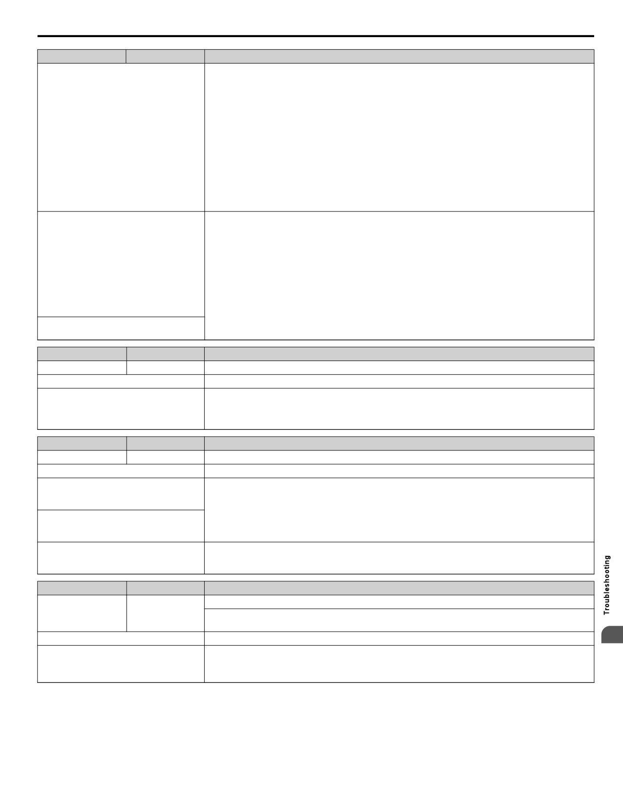
6.5 Operator Programming Errors
LED Display
LCD Display
Error Name
Settings for N.C. and N.O. input for the
following functions were selected
simultaneously:
• External Search Command 1 and External
Search Command 2 (61 vs. 62)
• Fast Stop N.O. and Fast Stop N.C. (15 vs.
17)
• Check if contradictory settings have simultaneously been assigned to the multi-function input terminals.
• KEB Command 1 and KEB Command 2
• Correct setting errors.
(65, 66 vs. 7A, 7B)
• FWD Run Command (or REV) and FWD/
REV Run Command (2-wire) (40, 41 vs.
42, 43)
• External DB Command and Drive Enable
(60 vs. 6A)
One of the following settings was entered
while H1-oo = 2 (External Reference 1/2):
• b1-15 = 4 (Pulse Train Input) but the pulse
train input selection is not set for the
frequency reference (H6-01 > 0)
• b1-15 or b1-16 set to 3 but no option card
Correct the settings for the multi-function input terminal parameters.
is connected
• Although b1-15 = 1 (Analog Input) and
H3-02 or H3-10 are set to 0 (Frequency
Bias)
H2-oo is set to 38 (Drive Enabled) and H1-
oo is not set to 6A (Drive Enable).
LED Display
LCD Display
Error Name
ope04
oPE04
Initialization Required, Term <-> Ctrl Chg
Cause
Possible Solutions
The drive, control board, or terminal board
have been replaced and the parameter
• Set A1-03 to 5550 to load the parameter settings stored in the terminal board to the drive.
settings between the control board and the
• Initialize parameters after drive replacement by setting A1-03 to 1110 or 2220.
terminal board no longer match.
LED Display
LCD Display
Error Name
ope05
oPE05
Run Command/Frequency Reference Source Selection Error
Cause
Possible Solutions
Frequency reference is assigned to an option
card (b1-01 = 3) and an input option card is
not connected to the drive.
Reconnect the input option card to the drive.
The Run command is assigned to an option
card (b1-02 = 3) and an input option card is
not connected to the drive.
Frequency reference is assigned to the pulse
train input (b1-01 = 4) and terminal RP is not
Set H6-01 to 0.
set for frequency reference input (H6-01 > 0)
LED Display
LCD Display
Error Name
Multi-Function Analog Input Selection Error
ope07
oPE07
A contradictory setting is assigned to multi-function analog inputs H3-02 or H3-10 and PID functions
conflict.
Cause
Possible Solutions
6
Change the settings to H3-02 or H3-10 so that functions no longer conflict.
H3-02 and H3-10 are set to the same value.
Note:
Both 0 (Frequency Reference Bias) and F (Not Used) can be set to H3-02 or H3-10
simultaneously.
281
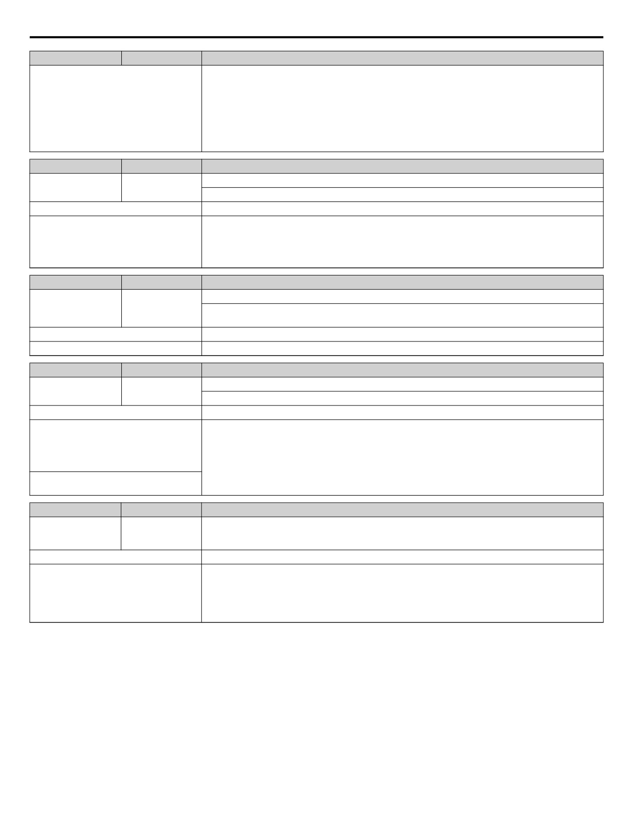
6.5 Operator Programming Errors
LED Display
LCD Display
Error Name
The following simultaneous contradictory
settings:
• H3-02 or H3-06 = B (PID Feedback) while
H6-01
Disable one of the PID selections.
(Pulse Train Input) = 1 (PID Feedback)
• H3-02 or H3-06 = C (PID Target Value)
while H6-01 = 2
(pulse train input sets the PID target value)
LED Display
LCD Display
Error Name
PID Control Selection Fault
ope09
oPE09
PID control function selection is incorrect. Requires that PID control is enabled (b5-01 = 1).
Cause
Possible Solutions
b5-01 is set to 1 or 2, enabling PID control,
but the lower limit for the frequency
reference (d2-02) is not set to 0 while reverse
Correct the parameter settings.
output is enabled
(b5-11 = 1).
LED Display
LCD Display
Error Name
V/f Data Setting Error
ope10
oPE10
One of the following setting errors has occurred:
E1-09 ≤ E1-07 < E1-06 ≤ E1-11 ≤ E1-04
Cause
Possible Solutions
V/f pattern setting error.
Correct the settings for E1-04, E1-06, E1-07, E1-09, and E1-11.
LED Display
LCD Display
Error Name
Carrier Frequency Setting Error
ope11
oPE11
Correct the setting for the carrier frequency.
Cause
Possible Solutions
The following simultaneous contradictory
settings have occurred: C6-05 > 6 and C6-04
> C6-03 (carrier frequency lower limit is
greater than the upper limit).
Correct the parameter settings.
If C6-05 ≤ 6, the drive operates at C6-03.
The upper and lower limits between C6-02
and C6-05 are contradictory.
LED Display
LCD Display
Error Name
oPE33
ope33
Net
Parameter selection is incompatible with the selected network P9-99
Incompatible
Cause
Possible Solutions
When P1-01 = 3 (MEMOBUS Networking)
and P9-99 = 0 (A-Version 30034), one of the
following parameters has been set:
Confirm parameter settings for P1-01, P9-01, P9-99, and P9-05.
• P9-01 = 2 (Stop History)
• P9-05 = 3 (Follow Lead Speed)
282
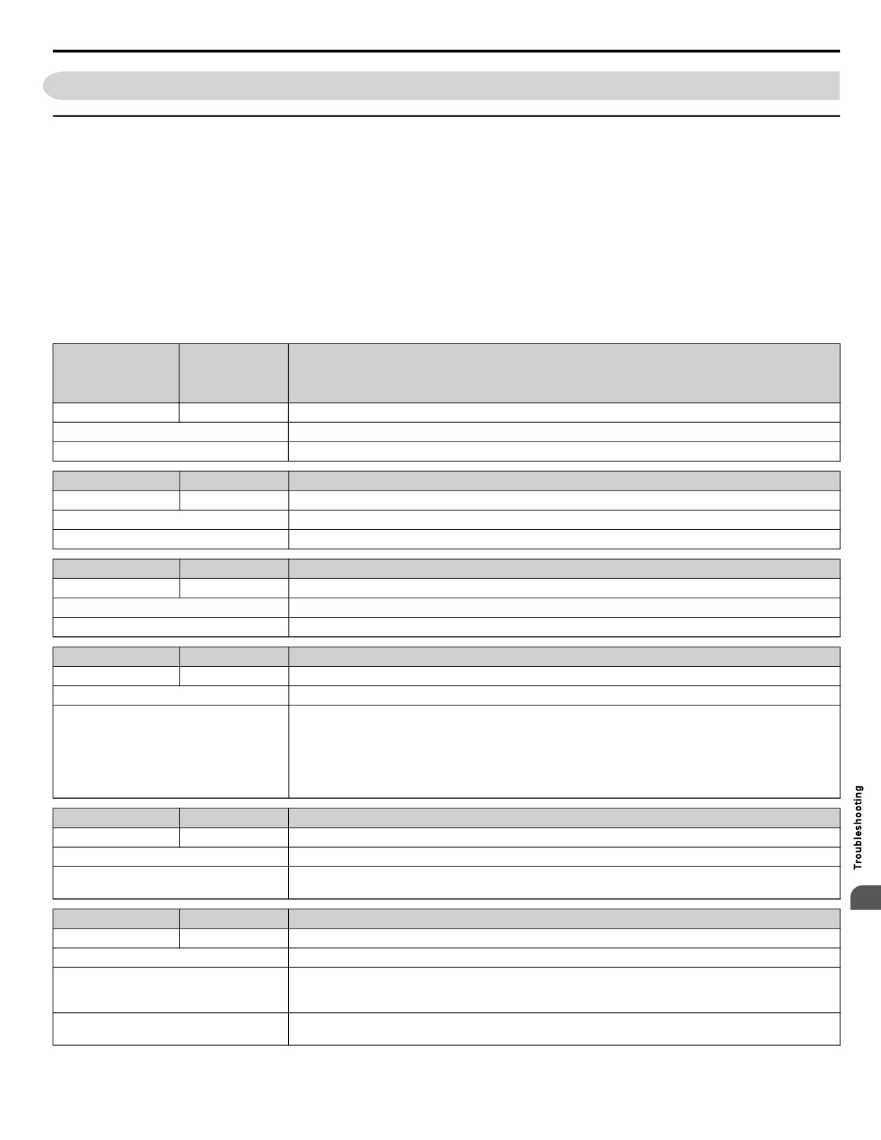
6.6 Copy Function Related Displays
6.6
Copy Function Related Displays
u Tasks, Errors, and Troubleshooting
The table below lists the messages and errors that may appear when using the Copy function.
When executing the tasks offered by the Copy function, the keypad will indicate the task being performed. When an error
occurs, a code appears on the keypad to indicate the error. Note that errors related to the Copy function do not trigger a multi-
function output terminal that has been set up to close when a fault or alarm occurs. To clear an error, simply press any key on
the keypad and the error display will disappear.
Table 6.5 lists the corrective action that can be taken when an error occurs.
Note:
1. The drive should be fully stopped when using the copy function.
2. The drive will not accept a Run command while the Copy function is being executed.
3. Parameters can only be saved to a drive when the voltage class, capacity, control mode, and software version match.
Table 6.5 Copy Function Task and Error Displays
LED Display
LCD Display
Task
copy
CoPy
Writing Parameter Settings (flashing)
Cause
Possible Solutions
Parameters are being written to the drive.
This is not an error.
LED Display
LCD Display
Task
cpye
CoPyE
Error Writing Data
Cause
Possible Solutions
Failed writing parameters
Attempt to write parameters again.
LED Display
LCD Display
Task
c5er
CSEr
Copy Unit Error
Cause
Possible Solutions
Hardware fault
Replace the HOA keypad or the USB Copy Unit.
LED Display
LCD Display
Task
dfp5
dFPS
Drive Model Mismatch
Cause
Possible Solutions
The drives used in the copy and write process
are not the same model.
• Verify the model number of the drive from which the parameters were copied and the model of the drive
• The drive from which the parameters were
to which those parameters will be written.
copied is a different model.
• Make sure the two drives are the same model and have the same software version.
• The drive to be written to is a different
model.
LED Display
LCD Display
Task
end
End
Task Complete
Cause
Possible Solutions
Finished reading, writing, or verifying
This is not an error.
parameters.
6
LED Display
LCD Display
Task
ifer
iFEr
Communication Error
Cause
Possible Solutions
A communication error occurred between
the drive and the HOA keypad or the USB
Check the cable connection.
copy unit.
A non-compatible cable is being used to
Use the cable originally packaged with the USB Copy Unit.
connect the USB Copy Unit and the drive.
283
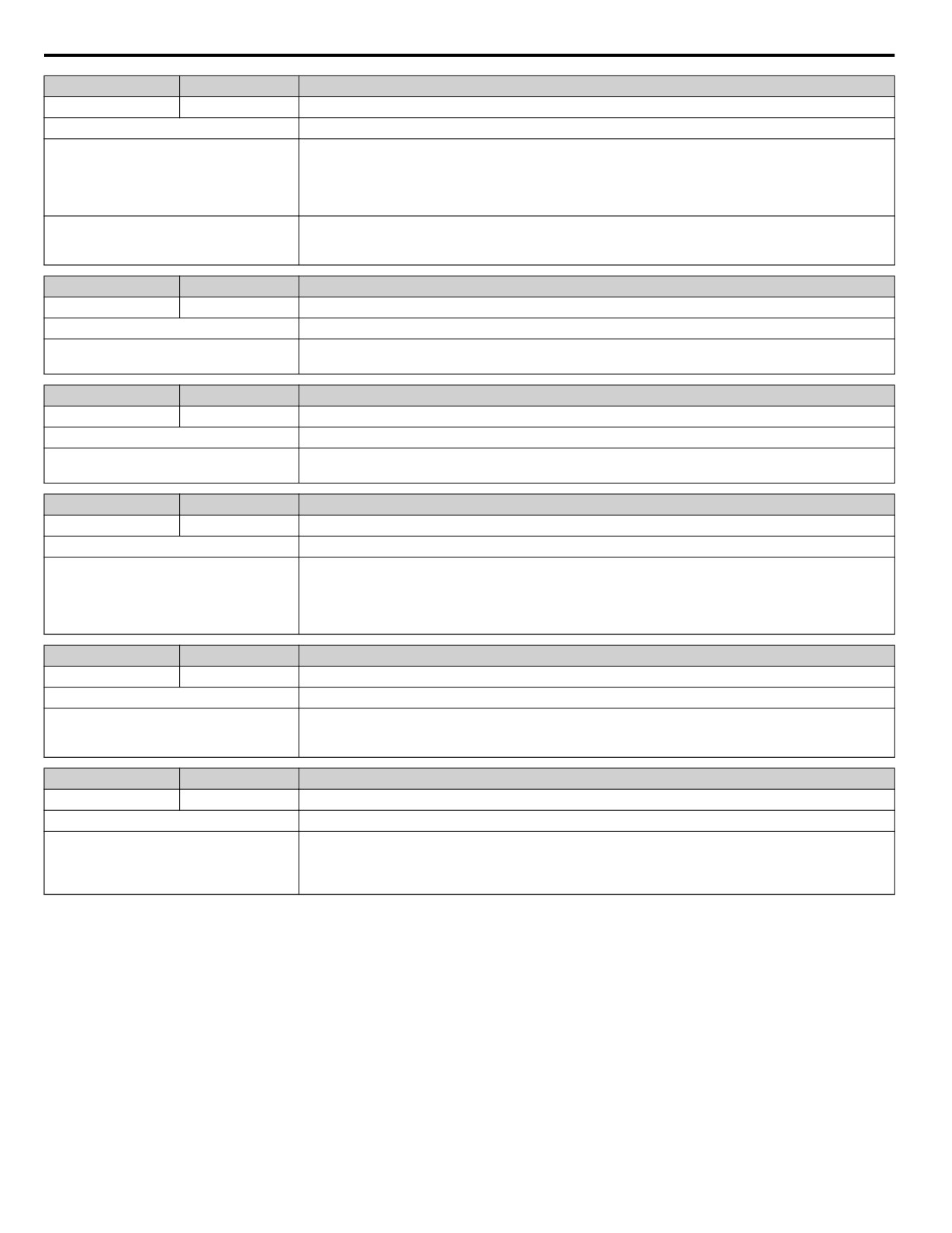
6.6 Copy Function Related Displays
LED Display
LCD Display
Task
ndat
ndAT
Model, Voltage Class, Capacity Mismatch
Cause
Possible Solutions
The drive from which the parameters were
copied and the drive to which the parameters
will be written have different electrical
Make sure model numbers and specifications are the same for both drives.
specifications, capacities, are set to different
control modes, or are different models.
The device being used to write the
Make sure all connections are correct, and copy the parameter settings onto the USB Copy Unit or the HOA
parameters is blank and does not have any
keypad.
parameters saved on it.
LED Display
LCD Display
Task
rder
rdEr
Error Reading Data
Cause
Possible Solutions
Failed while attempting to read parameter
Press and hold the READ key on the USB Copy Unit for at least one second to have the unit read parameters
settings from the drive.
from the drive.
LED Display
LCD Display
Task
read
rEAd
Reading Parameter Settings (flashing)
Cause
Possible Solutions
Displayed while the parameter settings are
This is not an error.
being read onto the USB Copy Unit.
LED Display
LCD Display
Task
uAEr
vAEr
Voltage Class, Capacity Mismatch
Cause
Possible Solutions
The drive from which the parameters were
copied and the drive on which the Verify
mode is being performed have different
Make sure electrical specifications and capacities are the same for both drives.
electrical specifications or are a different
capacity.
LED Display
LCD Display
Task
ufyE
vFyE
Parameter settings in the drive and those saved to the copy function are not the same
Cause
Possible Solutions
Indicates that parameter settings that have
To synchronize parameters, either write the parameters saved on the USB Copy Unit or HOA keypad onto
been Read and loaded onto the Copy Unit or
the drive, or Read the parameter settings on the drive onto the USB Copy Unit.
HOA keypad are different.
LED Display
LCD Display
Task
urfy
vrFy
Comparing Parameter Settings (flashing)
Cause
Possible Solutions
The Verify mode has confirmed that
parameters settings on the drive and
This is not an error.
parameters read to the copy device are
identical.
284
6.7 Digital Operator Display Messages
6.7
Digital Operator Display Messages
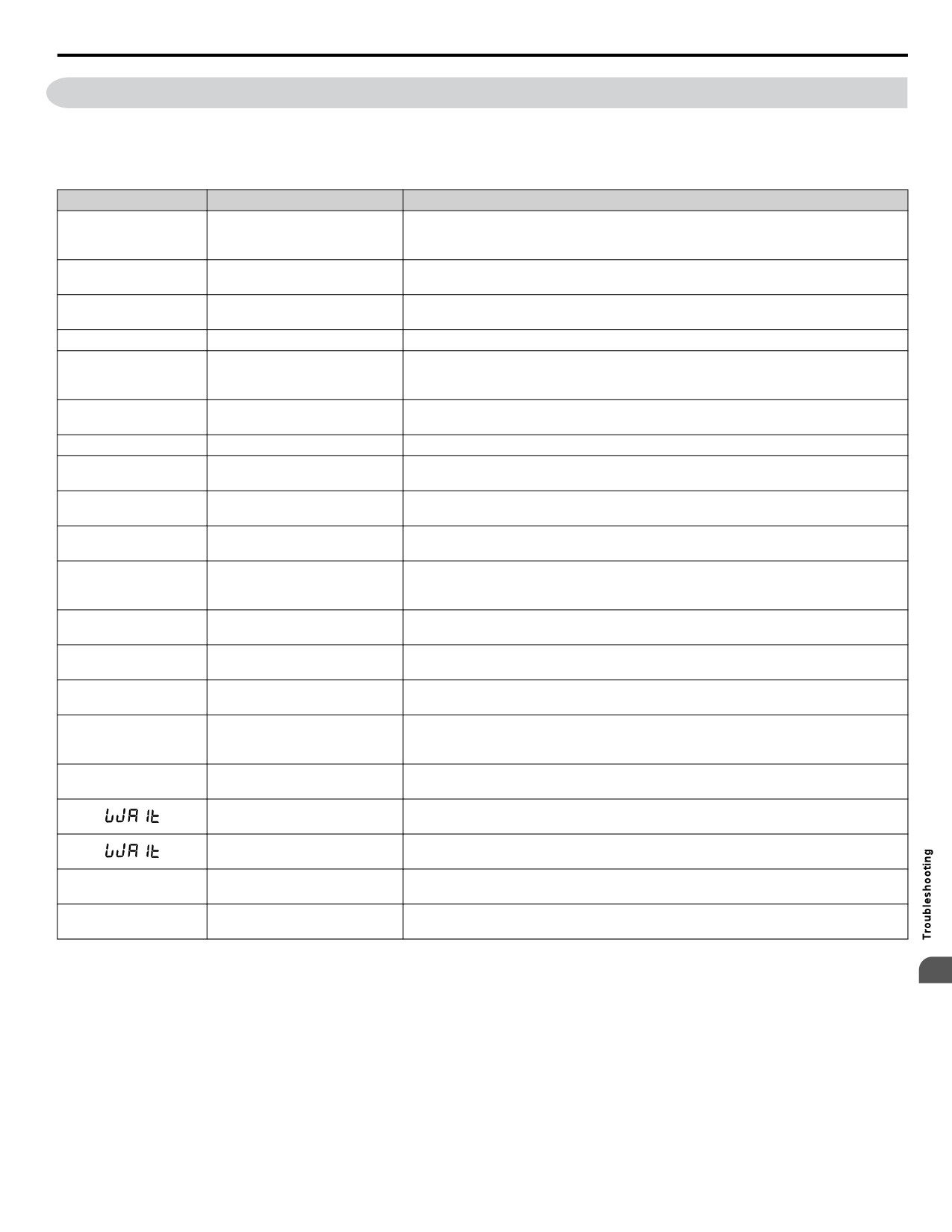
Table 6.6 lists messages and errors that may appear during normal pump operation.
These messages do not trigger multi-function output terminals that have been set up to close when a fault or alarm occurs.
Table 6.6
Digital Operator Display Messages
LED Display
LCD Display
Description
Fault reset was being executed when a Run command was entered. Ensure that a Run
CrST
cr5t
command cannot be entered from the external terminals or option during fault reset. Turn
Cannot Reset
off the Run command.
Displayed when drive output speed is being limited due to the output current limit. Reduce
cvr
Current Limit Foldback
the load or replace with higher capacity drive.
Displayed during multiplexing when drive de-staging is in progress. X sec indicates the
d5tge
De-staging in X sec
time left before the de-staging takes place.
no indication
DigitalOut Delay Active
Displayed when the Digital Output Delay function is active.
Displayed when the drive is determining whether the feedback will change abruptly when
fbcH-
Feedback Drop Check
the drive enters Sleep Mode. Drop Level is configured by P2-08, Delta Sleep Feedback
Drop Level, and P2-09 Feedback Detection Drop Time.
LOCK
Displayed after an attempt to change a parameter when A1-01 = 3. Unlock the keypad by
loc-p
Parameter Locked
setting A1-01 = 2.
no indication
Lube Pump Active
Displayed when the Lube Pump digital output is energized.
Net Pump Err
Displayed when the drive has been stopped because another drive in the network has a
neter
Chk Faulted Pump
system fault or a Low City Pressure alarm.
Net Start Delay
net5t
Displayed when the MEMOBUS network is waiting for the P9-29 timer to elapse.
P9-29 Active
Network FB Lost
Displayed when no valid analog PID feedback source can be found on the network and
netfb
Check FB Source
network PID feedback has been lost.
PASS
pa55
MEMOBUS/Modbus Comm.
MEMOBUS/Modbus test has finished normally.
Test Mode Complete
Pre Chg Mode
Pre-charge 1 or 2 active. X indicates time left before pre-charge exits due to timers
prchg
Exit in Xsec
(P4-03 + P4-07).
Displayed when an input phase has been lost, or when excess load is being drawn by the
1ph
Single Phase Foldback
motor in a single phase application.
Sleep Active Wait for
Displayed when the drive is in Sleep Mode or when the drive is waiting for the feedback
5leep
Start
level to reach the level set in P1-04, Start Level.
Displayed when the drive entering Sleep Mode and the pressure setpoint is being boosted.
boo5t
Sleep Boost Active
During this time, the U1-01, Frequency Reference, monitor will be updated with the
boosted setpoint.
Displayed during multiplexing when drive staging is in progress. X sec indicates the time
5tage
Staging in X sec
left before the staging takes place.
Displayed when the drive start is being delayed by Coast to Stop with Timer (Back Spin
Start Delay Adjust b1-11
Timer). This time is adjusted by parameter b1-11, Coast to Stop with Timer Time.
Displayed when the feedback level has reached the level set in P1-04, Start Level, and the
Start Delay Timer Active
Start Delay timer is incrementing.
Thrust Mode
thr5t
Displayed during Thrust Mode.
Thrust Active
Utility Delay Adjust by
Displayed when the drive is delaying the Run command due to the Utility Start Delay
vt1l
P4-17
Function.
6
285
6.7 Digital Operator Display Messages
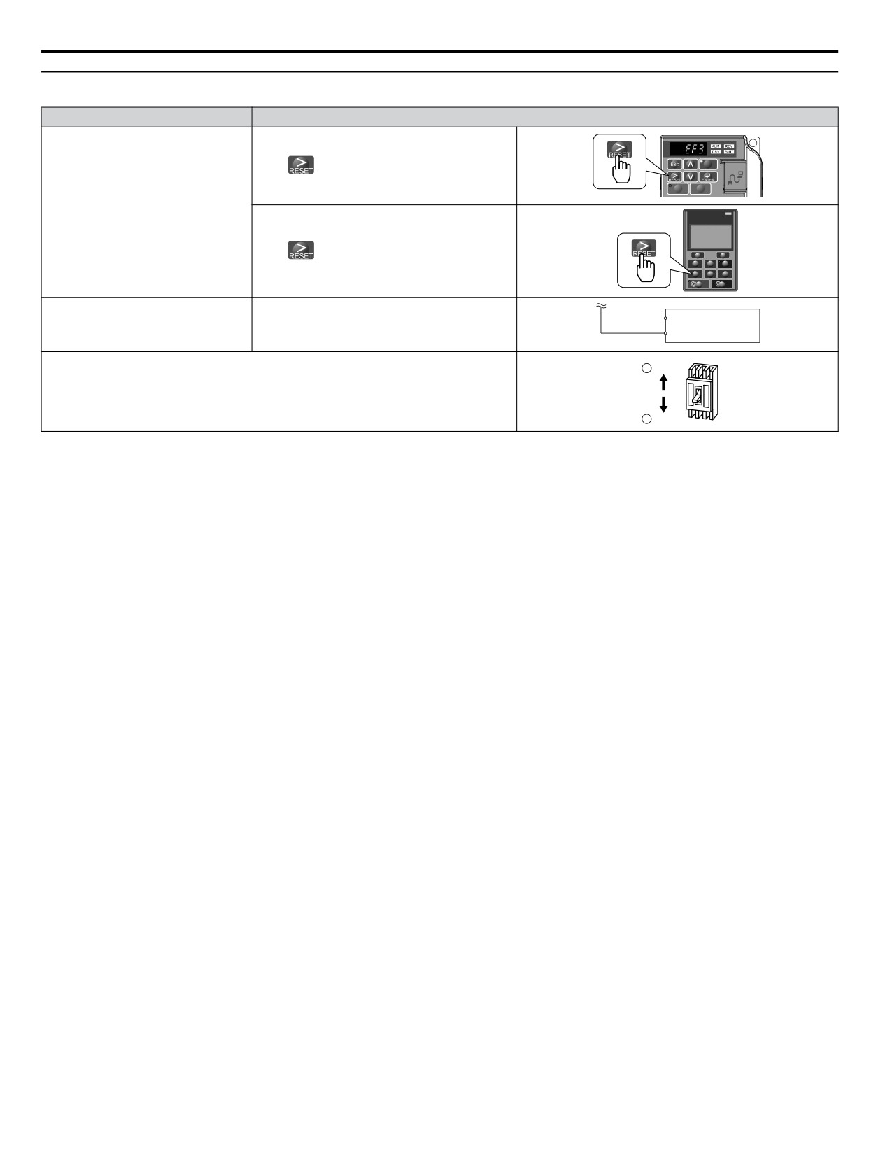
u Fault Reset Methods
After the Fault Occurs
Procedure
Press
on the digital operator.
Fix the cause of the fault, restart the
DIGITAL OPERATOR JVOP-183
ALM
drive, and reset the fault
-DRIVE-
-Rdy-
Freq Ref (OPR)
U1- 01=60.00Hz
----------------
U1- 02=60.00Hz
JOG FWD FWD/REV
F1
F2
Press
on the optional HOA keypad.
M M
ESC
HAND
RESET
ENTER
AUTO
OFF
Drive
Close then open the fault signal digital input via
Fault Reset Switch
Fix the cause of the fault and reset via
S4 Fault Reset Digital Input
terminal S4. S4 is set fault reset as default
Fault Reset Digital Input S4.
SC Digital Input Common
(H1-04 = 12).
2
ON
Turn off the main power supply if the above methods do not reset the fault. Reapply power
after the digital operator display has turned off.
1
OFF
286
7
Periodic Inspection & Maintenance
This chapter describes the periodic inspection and maintenance of the drive to ensure that it receives
the proper care to maintain overall performance.
7.1
SECTION SAFETY
288
7.2
INSPECTION
290
7.3
PERIODIC MAINTENANCE
292
7.4
DRIVE COOLING FANS
294
7.5
DRIVE REPLACEMENT
301
287
7.1 Section Safety
7.1
Section Safety
DANGER
Electrical Shock Hazard
Do not connect or disconnect wiring while the power is on.
Failure to comply will result in death or serious injury.
WARNING
Electrical Shock Hazard
Do not operate equipment with covers removed.
Failure to comply could result in death or serious injury.
The diagrams in this section may show drives without covers or safety shields to show details. Be sure to reinstall covers or
shields before operating the drives and run the drives according to the instructions described in this manual.
Always ground the motor-side grounding terminal.
Improper equipment grounding could result in death or serious injury by contacting the motor case.
Do not remove covers or touch circuit boards while the power is on.
Failure to comply could result in death or serious injury.
Do not allow unqualified personnel to perform work on the drive.
Failure to comply could result in death or serious injury.
Installation, maintenance, inspection, and servicing must be performed only by authorized personnel familiar with
installation, adjustment, and maintenance of AC drives.
Do not perform work on the drive while wearing loose clothing, jewelry or without eye protection.
Failure to comply could result in death or serious injury.
Remove all metal objects such as watches and rings, secure loose clothing, and wear eye protection before beginning work
on the drive.
Do not touch any terminals before the capacitors have fully discharged.
Failure to comply could result in death or serious injury.
Before wiring terminals, disconnect all power to the equipment. The internal capacitor remains charged even after the power
supply is turned off. The charge indicator LED will extinguish when the DC bus voltage is below 50 Vdc. To prevent electric
shock, wait at least five minutes after all indicators are off and measure the DC bus voltage level to confirm safe level.
Fire Hazard
Tighten all terminal screws to the specified tightening torque.
Loose electrical connections could result in death or serious injury by fire due to overheating of electrical connections.
Do not use an improper voltage source.
Failure to comply could result in death or serious injury by fire.
Verify that the rated voltage of the drive matches the voltage of the incoming power supply before applying power.
Do not use improper combustible materials.
Failure to comply could result in death or serious injury by fire.
Attach the drive to metal or other noncombustible material.
288
7.1 Section Safety
NOTICE
Observe proper electrostatic discharge procedures (ESD) when handling the drive and circuit boards.
Failure to comply may result in ESD damage to the drive circuitry.
Never connect or disconnect the motor from the drive while the drive is outputting voltage.
Improper equipment sequencing could result in damage to the drive.
Do not use unshielded cable for control wiring.
Failure to comply may cause electrical interference resulting in poor system performance. Use shielded, twisted-pair wires
and ground the shield to the ground terminal of the drive.
Do not allow unqualified personnel to use the product.
Failure to comply could result in damage to the drive or braking circuit.
Carefully review instruction manual TOBPC72060000 when connecting a braking option to the drive.
Do not modify the drive circuitry.
Failure to comply could result in damage to the drive and will void warranty.
Yaskawa is not responsible for any modification of the product made by the user. This product must not be modified.
Check all the wiring to ensure that all connections are correct after installing the drive and connecting any other
devices.
Failure to comply could result in damage to the drive.
7
289
7.2 Inspection
7.2
Inspection
Power electronics have limited life and may exhibit changes in characteristics or performance deterioration after years of use
under normal conditions. To help avoid such problems, it is important to perform preventive maintenance and periodic
inspection on the drive.
Drives contain a variety of power electronics such as power transistors, semiconductors, capacitors, resistors, fans, and relays.
The electronics in the drive serve a critical role in maintaining proper motor control.
Follow the inspection lists provided in this chapter as a part of a regular maintenance program.
Note: The drive will require more frequent inspection if it is placed in harsh environments, such as:
• High ambient temperatures
• Frequent starting and stopping
• Fluctuations in the AC supply or load
• Excessive vibrations or shock loading
• Dust, metal dust, salt, sulfuric acid, chlorine atmospheres
• Poor storage conditions.
Perform the first equipment inspection one to two years after installation.
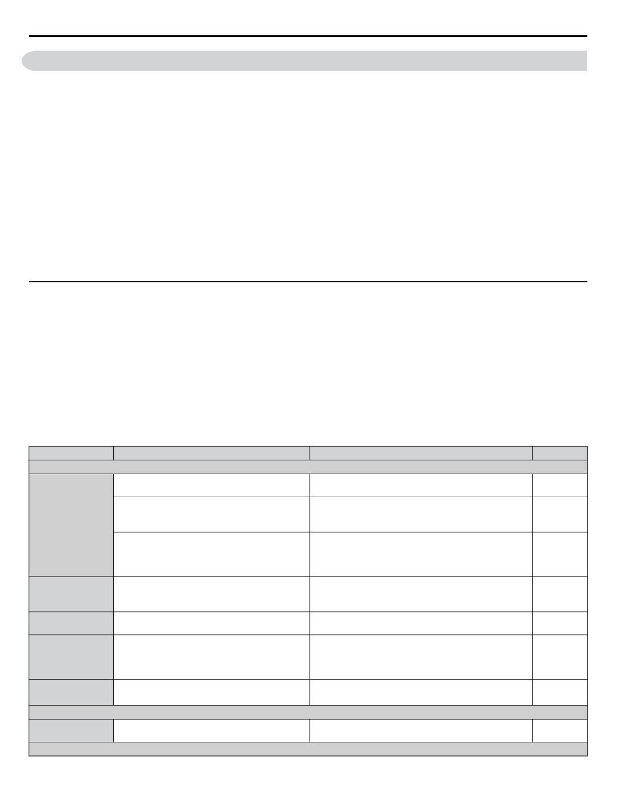
u Recommended Periodic Inspection
outlines the recommended periodic inspections for Yaskawa drive installations. Although periodic inspections should generally
be performed once a year; the drive may require more frequent inspection in harsh environments or with rigorous use. Operating
and environmental conditions, along with experience in each application, will determine the actual inspection frequency for
each installation. Periodic inspection will help to avoid premature deterioration in performance or product failure. Copy this
checklist and mark the “Checked” column after each inspection.
n Periodic Inspection
WARNING! Electrical Shock Hazard. Do not connect or disconnect wiring while the power is on. Failure to comply can result in serious
personal injury. Before servicing the drive, disconnect all power to the equipment. The internal capacitor remains charged even after the
power supply is turned off. The charge indicator LED will extinguish when the DC bus voltage is below 50 Vdc. To prevent electric shock,
wait at least five minutes after all indicators are OFF and measure the DC bus voltage level to confirm safe level.
Table 7.1 Periodic Inspection Checklist
Inspection Area
Inspection Points
Corrective Action
Checked
Main Circuit Periodic Inspection
•
Overall check of the main power circuit and
Take appropriate actions (e.g., tightening loose
ground terminals
connections).
•
Inspect equipment for discoloration from
• Replace damaged components as required.
overheating or deterioration.
• The drive has few serviceable parts and may require
General
•
Inspect for damaged or deformed parts.
complete drive replacement.
• Inspect enclosure door seal if present. Replace
•
Inspect for dirt, foreign particles, or dust collection
components if cleaning is not possible.
on components.
• Remove foreign particles and dust with a vacuum cleaner
to avoid touching parts.
•
Inspect wiring and connections for discoloration,
Conductors and
damage, or heat stress.
• Repair or replace damaged wiring.
Wiring
•
Inspect wire insulation and shielding for wear.
•
Inspect terminals for stripped, damaged, or loose
• Tighten loose screws and replace damaged screws or
Terminals
connections.
terminals.
•
Inspect contactors and relays for excessive noise
• Check coil voltage for over or under voltage conditions.
Relays and
during operation.
• Replace damaged removable relays contactors or circuit
Contactors
•
Inspect coils for signs of overheating such as
board.
melted or cracked insulation.
•
Inspect for discoloration of heat stress on or around
• Minor discoloration may be acceptable.
Braking Resistors
resistors.
• If discoloration exists check for loose connections.
Motor Periodic Inspection
• Stop the motor and contact qualified maintenance
Operation Check
•
Check for increased vibration or abnormal noise.
personnel as required.
Control Circuit Periodic Inspection
290
7.2 Inspection
Inspection Area
Inspection Points
Corrective Action
Checked
• Tighten loose screws and replace damaged screws or
• Inspect terminals for stripped, damaged or loose
terminals.
General
connections.
• If terminals are integral to a circuit board then board or
• Check for tightness.
drive replacement may be required.
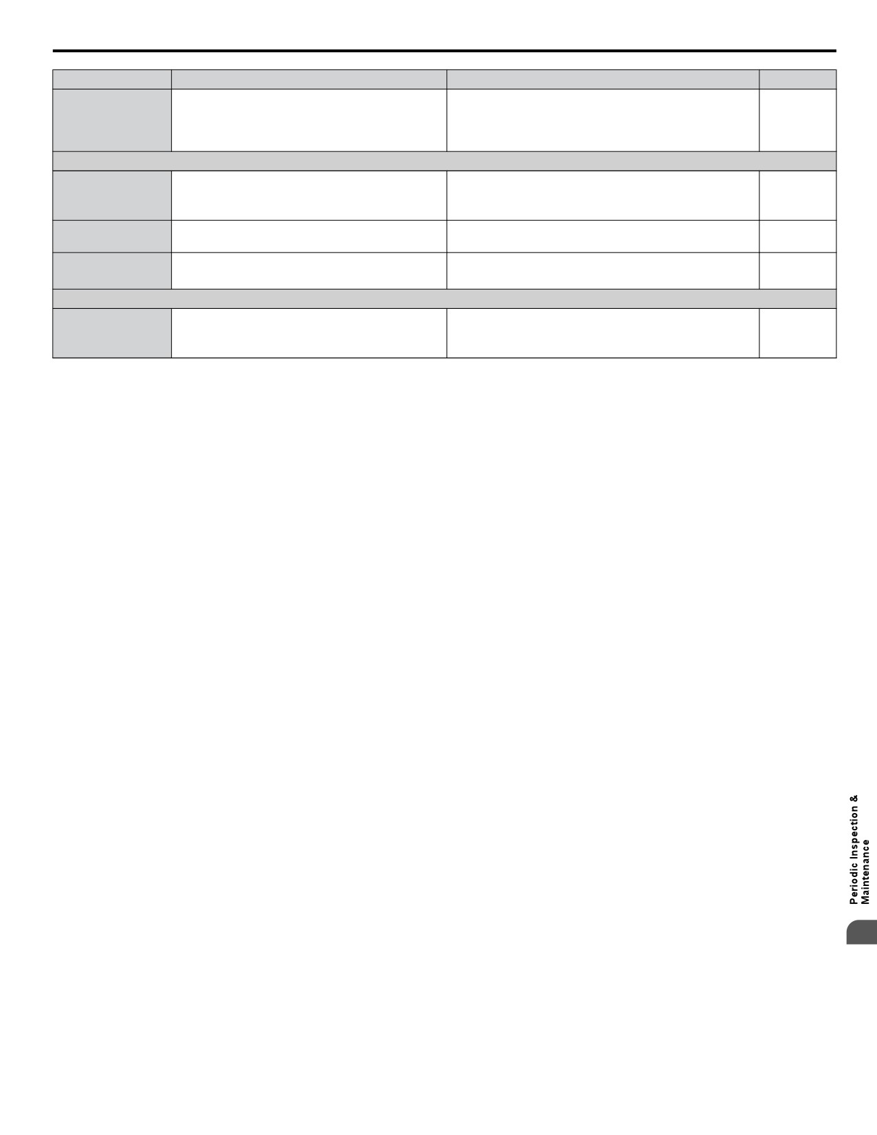
Cooling System Periodic Inspection
• Replace as required.
• Check for abnormal oscillation or unusual noise.
Cooling Fan
• Refer to Drive Cooling Fans on page 294 for information
• Check for damaged or missing fan blades.
on cleaning or replacing the cooling fan.
• Inspect for dust or other foreign material collected
• Remove foreign particles and dust with a vacuum cleaner
Heatsink
on the surface.
to avoid touching parts.
• Inspect air intake and exhaust openings. They must
• Visually inspect the area.
Air Duct
be free from obstruction and properly installed.
• Clear obstructions and clean air duct as required.
LED Periodic Inspection
• Make sure the LED lights correctly.
• Contact your Yaskawa representative if there is any
LEDs
• Inspect for dust or other foreign material that may
trouble with the LED or keypad.
have collected on surrounding components.
• Clean the LED.
Note:
Periodic inspections should be performed every one or two years. The drive, however, may require more frequent inspection due to poor
environments or rigorous use.
7
291
7.3 Periodic Maintenance
7.3
Periodic Maintenance
The drive has various "maintenance monitors." This feature provides advance maintenance warning and eliminates the need
to shut down the entire system for unexpected problems. The drive allows the user to check the following maintenance periods.
• Cooling Fan
• Electrolytic Capacitors (Main Circuit)
• Inrush Prevention Circuit
• IGBT
u Replacement Parts
Table 7.2 contains the estimated performance life of components that require replacement during the life of the drive. Only
use Yaskawa replacement parts for the appropriate drive model and revision.
Table 7.2 Estimated Performance Life
Component
Estimated Performance Life
Cooling Fan
10 years
Electrolytic Capacitors (Main Circuit)
10 years <1>
<1> The drive has few serviceable parts and may require complete drive replacement.
NOTICE: Estimated performance life based on specific usage conditions. These conditions are provided for the purpose of replacing parts
to maintain performance. Some parts may require more frequent replacement due to poor environments or rigorous use.
Usage conditions for estimated performance life:
• Ambient temperature: Yearly average of 40 °C
• Load factor: 80% maximum
• Operation time: 24 hours a day
n Performance Life Monitors
The drive calculates the maintenance period for components that may require replacement during the life of the drive. A
percentage of the maintenance period is displayed on the LED digital operator by viewing the appropriate monitor parameter.
When the maintenance period reaches 100%, there is increased risk that the drive may malfunction. Yaskawa recommends
checking the maintenance period regularly to ensure maximum performance life.
Table 7.3 Performance Life Monitors Used for Component Replacement
Parameter
Component
Contents
Displays the accumulated operation time of the cooling fan, from 0 to 99999 hours. This value is
U4-03
automatically reset to 0 once it reaches 99999.
Cooling Fan
Displays the accumulated cooling fan operation time as a percentage of the specified maintenance
U4-04
period (displayed in percent %).
Main Circuit (DC bus)
Displays the accumulated time the capacitors are used as a percentage of the specified maintenance
U4-05
Electrolytic Capacitors
period.
Displays the number of times the drive is powered up as a percentage of the performance life of
U4-06
Inrush (pre-charge) relay
the inrush circuit.
U4-07
IGBT
Displays the percentage of the maintenance period reached by the IGBTs.
292
7.3 Periodic Maintenance
n Alarm Outputs for Maintenance Monitors
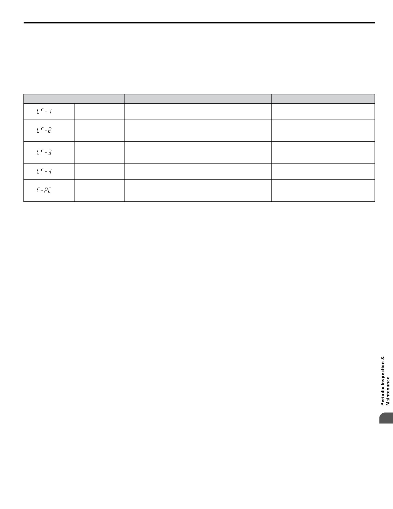
An output can be set up to inform the user when a specific components has neared its expected performance life.
When one of multi-function digital output terminals has been assigned the maintenance monitor function (H2-oo = 2F), the
terminal will close when the cooling fan, DC bus capacitors, or DC bus pre-charge relay reach 90% of the expected performance
life, or when the IGBTs have reached 50% of their expected performance life. Additionally the digital operator will display
an alarm like shown in Table 7.4 to indicate the specific components that may need maintenance.
Table 7.4 Maintenance Alarms
Digital Operator Alarm Display
Function
Corrective Action
<1>
The cooling fans have reached 90% of their designated
LT-1
Replace the cooling fan.
life time.
Contact a Yaskawa representative or the
<1>
The DC bus capacitors have reached 90% of their
LT-2
nearest Yaskawa sales office on
designated life time.
possible drive replacement.
Contact a Yaskawa representative or the
<1>
The DC bus charge circuit has reached 90% of its
LT-3
nearest Yaskawa sales office on
designated life time.
possible drive replacement.
<1>
The IGBTs have reached 50% of their designated life
Check the load, carrier frequency, and
LT-4
time.
output frequency.
Contact a Yaskawa representative or the
<2>
The IGBTs have reached 90% of their designated life
TrPC
nearest Yaskawa sales office on
time.
possible drive replacement.
<1> This alarm message will be output only if the Maintenance Monitor function is assigned to one of the digital outputs (H2-oo = 2F). The alarm
will also trigger a digital output that is programmed for alarm indication (H2-oo = 10).
<2> This alarm message will always be output, even if the Maintenance Monitor function is not assigned to any of the digital outputs (H2-oo = 2F).
The alarm will also trigger a digital output that is programmed for alarm indication (H2-oo = 10).
n Related Drive Parameters
Use parameters o4-03, o4-05, o4-07, and o4-09 to reset a Maintenance Monitor to zero after replacing a specific component.
Refer to Parameter List on page 317 for details on parameter settings.
NOTICE: If these parameters are not reset after the corresponding parts have been replaced, the Maintenance Monitor function will continue
to count down the performance life from the value that was reached with the old part. If the Maintenance Monitor is not reset, the drive will
not have the correct value of the performance life for the new component.
7
293
7.4 Drive Cooling Fans
7.4
Drive Cooling Fans
NOTICE: Follow cooling fan replacement instructions. The cooling fan cannot operate properly when installed incorrectly and could seriously
damage the drive. To ensure maximum useful product life, replace all cooling fans when performing maintenance.
Contact your Yaskawa representative or supplier to order replacement cooling fans as required.
Some drive models have multiple cooling fans.
For drives with multiple cooling fans, replace all the fans when performing maintenance to ensure maximum useful product
life.
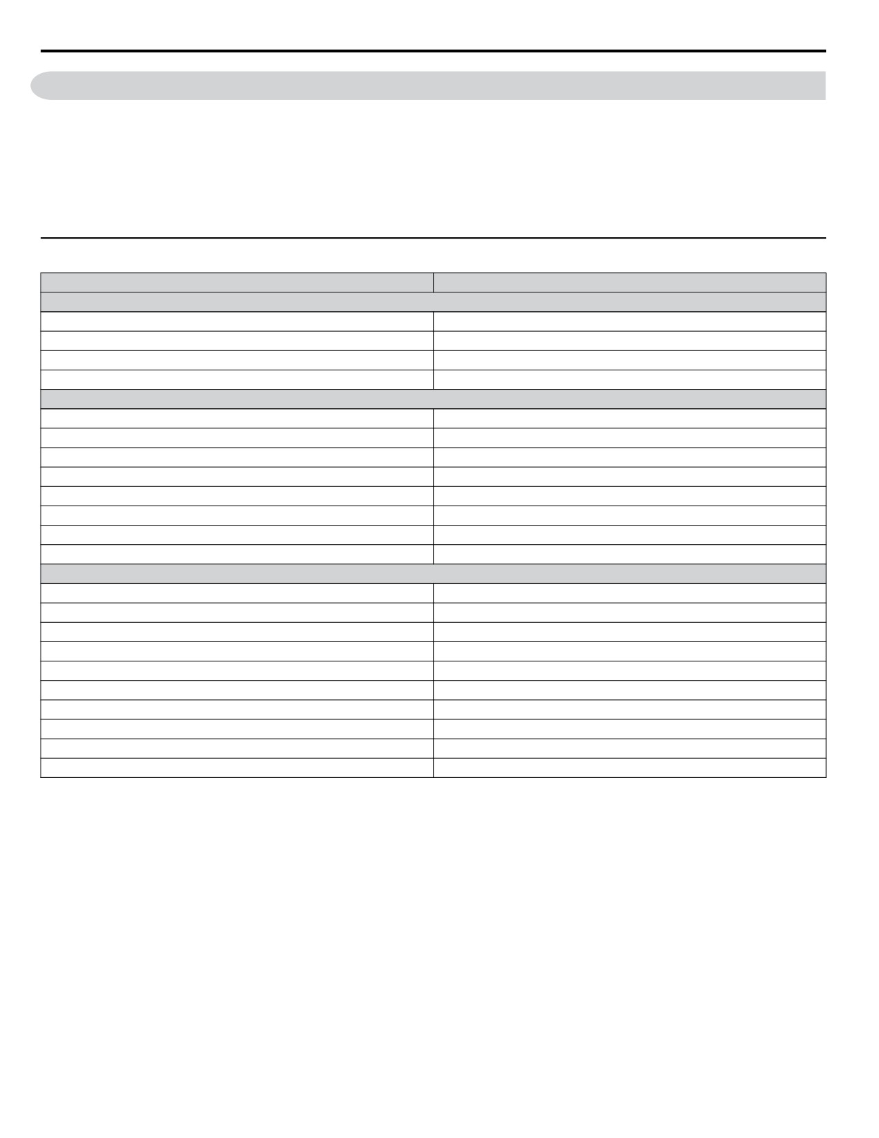
u Number of IP20/NEMA 1, UL Type 1 Cooling Fans
Drive Model
Cooling Fans
Single-Phase 200 V Class
BV0006F
-
BV0010F
1
BV0012F
1
BV0018F
2
Three-Phase 200 V Class
2V0006F
1
2V0010F
1
2V0012F
1
2V0020F
1
2V0030F
2
2V0040F
2
2V0056F
2
2V0069F
2
Three-Phase 400 V Class
4V0002F
-
4V0004F
-
4V0005F
1
4V0007F
1
4V0009F
1
4V0011F
1
4V0018F
2
4V0023F
2
4V0031F
2
4V0038F
2
294
7.4 Drive Cooling Fans
u IP20/NEMA 1, UL Type 1 Cooling Fan Replacement
The cooling fan is installed on the top of the drive. The cooling fan can easily be replaced without tools or removal of the drive
or enclosure parts.
WARNING! Electrical Shock Hazard. Do not connect or disconnect wiring while the power is on. Failure to comply can result in serious
personal injury. Before servicing the drive, disconnect all power to the equipment. The internal capacitor remains charged even after the
power supply is turned off. The charge indicator LED will extinguish when the DC bus voltage is below 50 Vdc. To prevent electric shock,
wait at least five minutes after all indicators are OFF and measure the DC bus voltage level to confirm safe level.
CAUTION! Burn Hazard. Do not touch a hot drive heatsink. Failure to comply could result in minor or moderate injury. Shut off the power
to the drive when replacing the cooling fan. To prevent burns, wait at least 15 minutes and ensure the heatsink has cooled down.
u Cooling Fan Replacement
The cooling fan is installed on the top of the drive. The cooling fan can easily be replaced without tools or removal of the drive
or enclosure parts.
WARNING! Electrical Shock Hazard. Do not connect or disconnect wiring while the power is on. Failure to comply can result in serious
personal injury. Before servicing the drive, disconnect all power to the equipment. The internal capacitor remains charged even after the
power supply is turned off. The charge indicator LED will extinguish when the DC bus voltage is below 50 Vdc. To prevent electric shock,
wait at least five minutes after all indicators are OFF and measure the DC bus voltage level to confirm safe level.
CAUTION! Burn Hazard. Do not touch a hot drive heatsink. Failure to comply could result in minor or moderate injury. Shut off the power
to the drive when replacing the cooling fan. To prevent burns, wait at least 15 minutes and ensure the heatsink has cooled down.
n Removing the Cooling Fan
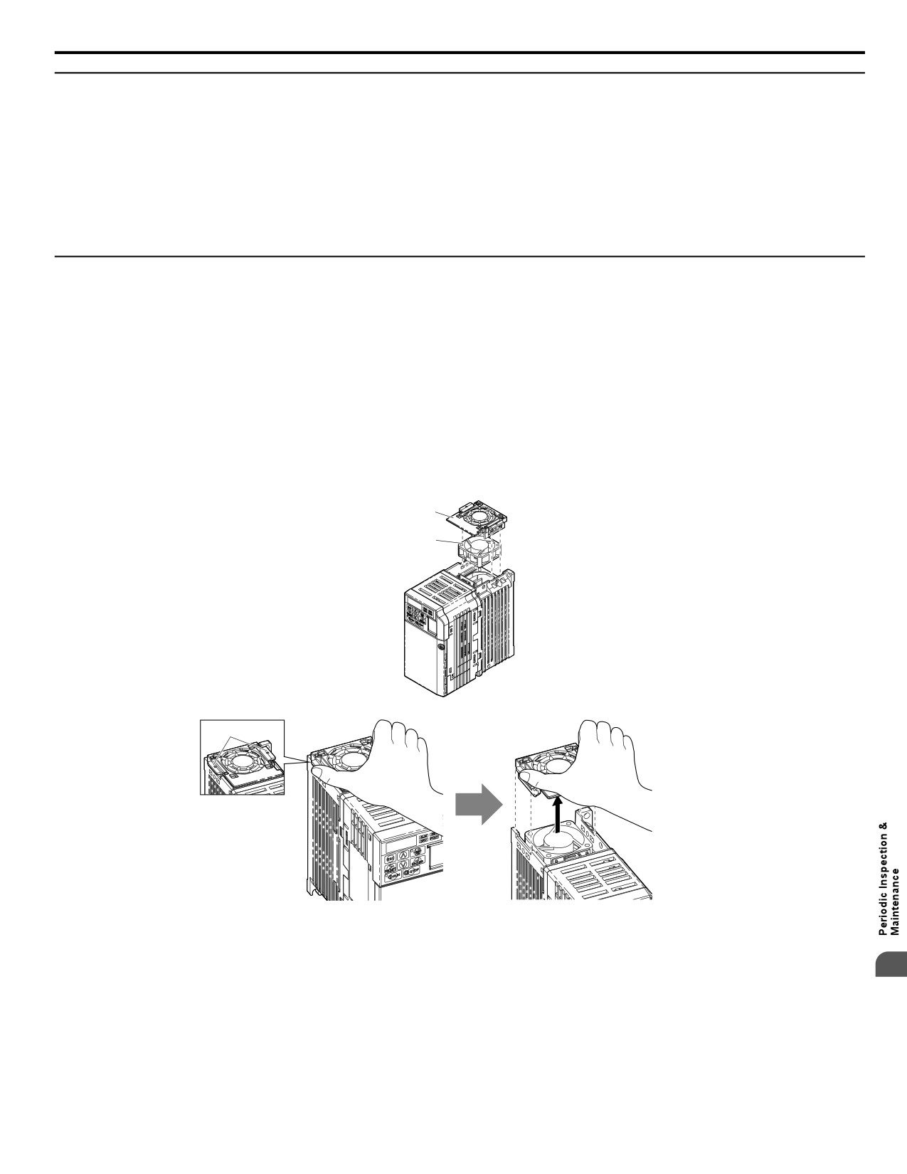
1. Depress the right and left sides of the fan cover tabs and pull upward. Remove the fan cover from the top of the drive.
The following figure illustrates a drive with a single cooling fan.
A
B
C
A - Fan cover
C - Tab
B - Cooling fan
Figure 7.1 Remove the Cooling
Fan Cover
7
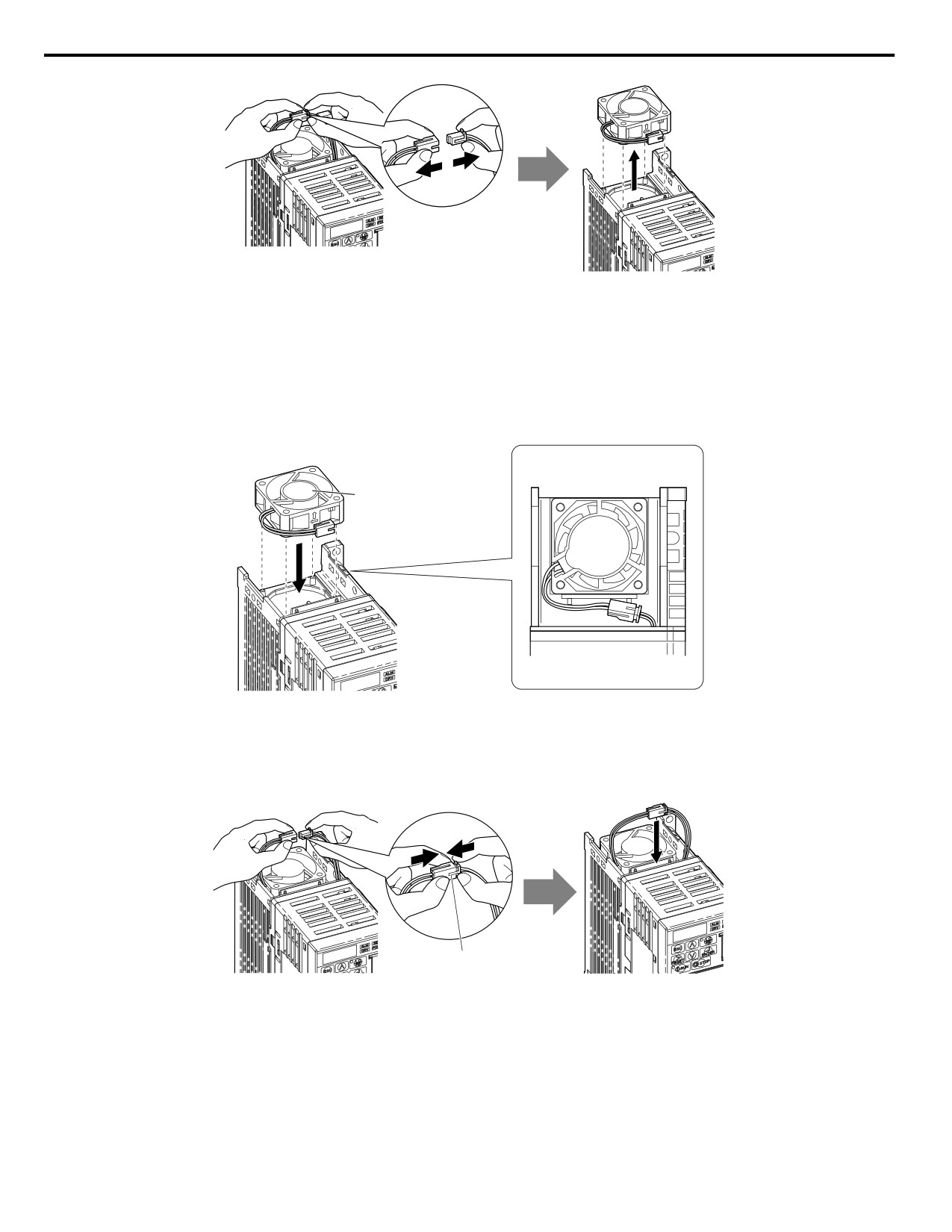
2. Remove the fan cable carefully, disconnect the pluggable connector
and
remove the
fan.
295
7.4 Drive Cooling Fans
Figure 7.2
Disconnect and Remove the
Fan
n Installing the Cooling Fan
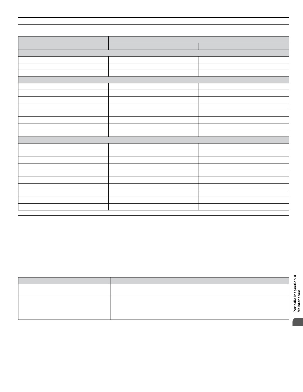
NOTICE: Prevent Equipment Damage. Follow cooling fan replacement instructions. Improper cooling fan replacement could result in
damage to equipment. When installing the replacement cooling fan into the drive, make sure the fan
is facing upwards. To ensure maximum
useful product life, replace all cooling fans when performing maintenance.
1. Install the replacement cooling fan into the drive, ensuring the alignment pins line up, as shown in the figure below:
B
A
C
A - Label
facing up
C - Front
B - Back
Figure 7.3
Cooling Fan Orientation
2. Ensure the connectors are properly connected and place the cable back into the recess of the drive.
A
A -Push the connectors together so no space remains between
them.
Figure 7.4 Connectors
Note:
Ensure that the left and right
tabs are locked
back into place.
3. Align the left and right cover tabs to install
the fan cover back on the top of the drive.
296
7.4 Drive Cooling Fans
u Number of IP66/NEMA 4X, UL Type 4X Cooling Fans
Number of Fans
Drive Model
Internal Fan
External Fan
Single-Phase 200 V Class
BV0006G
-
-
BV0010G
-
-
BV0012G
1
-
Three-Phase 200 V Class
2V0006G
-
-
2V0010G
-
-
2V0012G
-
-
2V0020G
1
-
2V0030G
1
1
2V0040G
1
1
2V0056G
1
1
2V0069G
1
2
Three-Phase 400 V Class
4V0002G
-
-
4V0004G
-
-
4V0005G
-
-
4V0007G
1
-
4V0009G
1
-
4V0011G
1
-
4V0018G
1
1
4V0023G
1
1
4V0031G
1
1
4V0038G
1
2
u IP66/NEMA 4X, UL Type 4X Cooling Fan Replacement
WARNING! Electrical Shock Hazard. Do not connect or disconnect wiring while the power is on. Failure to comply can result in serious
personal injury. Before servicing the drive, disconnect all power to the equipment. The internal capacitor remains charged even after the
power supply is turned off. The charge indicator LED will extinguish when the DC bus voltage is below 50 Vdc. To prevent electric shock,
wait at least five minutes after all indicators are OFF and measure the DC bus voltage level to confirm safe level.
CAUTION! Burn Hazard. Do not touch a hot drive heatsink. Failure to comply could result in minor or moderate injury. Shut off the power
to the drive when replacing the cooling fan. To prevent burns, wait at least 15 minutes and ensure the heatsink has cooled down.
n Required Additional Parts
Table 7.5 Additional Parts
Parts Sold Separately
Description
Contact your Yaskawa representative or the nearest Yaskawa sales office to order replacement
Cooling Fan
cooling fans as required.
Manufacturer: Shin-Etsu PN: KE3494
Description: Non-Flow, Electronic Grade RTV
RTV Sealant
North America: Shin-Etsu Silicones of America, Inc.
1150 Damar Street, Akron, Ohio 44305-1201
Phone: 800-544-1745, Fax: 330-630-9855, http://www.shinetsua.com/
7
297
7.4 Drive Cooling Fans
n Required Tools
Table 7.6 Tool Requirements
Tool
Single-Phase
Three-Phase
Three-Phase
200 V Class
200 V Class
400 V Class
4V0002G
2V0006G
4V0004G
BV0006G
2V0010G
4V0005G
8 mm socket wrench (cover removal)
BV0010G
2V0012G
4V0007G
BV0012G
2V0020G
4V0009G
4V0011G
2V0030G
4V0018G
2V0040G
4V0023G
10 mm socket wrench (cover removal)
-
2V0056G
4V0031G
2V0069G
4V0038G
7 mm socket wrench (fan removal)
All models
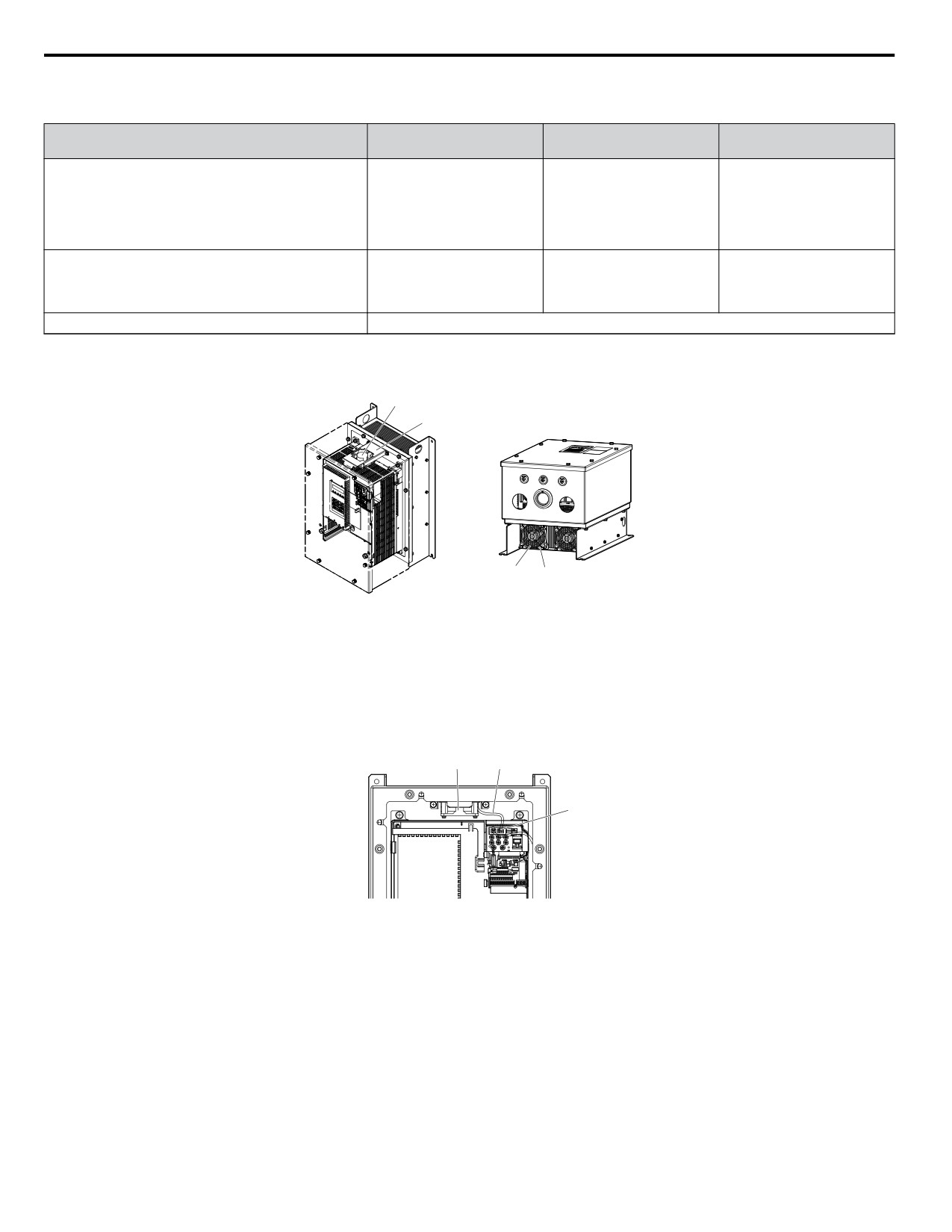
Refer to Figure 7.5 for internal fan and external fan locations.
Internal fan
External fan
A
B
A C
A - Fan
C - Fan guard
B - Fan support
Figure 7.5 Cooling Fan Location in Model 2V0069G
n Removing the Internal Fan
1. Remove the front cover. Refer to IP66/NEMA 4X, UL Type 4X Enclosure Front Cover Removal and Installation
on page 48 for details.
2. Unplug the fan connector (CN7).
A
B
C
A - Internal fan
C - Fan connector (CN7)
B - Fan relay cable
Figure
7.6 Internal Fan Components
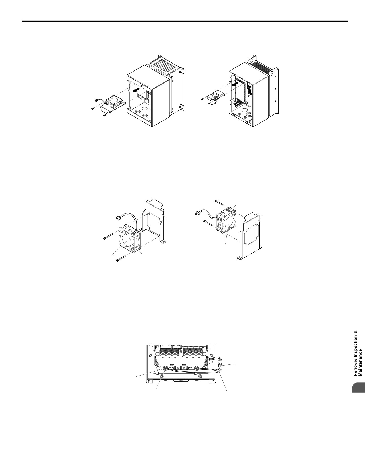
3. Loosen the screws holding the fan unit
in place then remove the fan unit from the drive.
298
7.4 Drive Cooling Fans
BV0012G
2V0020G
2V0030G to 2V0069G
4V0007G to 4V0011G
4V0018G to 4V0038G
Figure 7.7 Removing the Internal Fan
n Installing the Internal Fan
1. Fasten the replacement internal fan into place.
Note:
Pay special attention to the fan label direction, fan lead wire routing, and fan support bracket direction when connecting the
fan and the fan support in the drive.
BV0012G
2V0030G to 2V0069G
2V0020G
4V0018G to 4V0038G
4V0007G to 4V0011G
B
C
C
A
B
A
A - Label
C - Fan support
B - Cooling fan
Figure 7.8 Internal Fan Replacement
2. Install the fan unit back into the drive enclosure in its original position.
3. Plug the fan connector (CN7) back in.
n Removing the External Fan
1. Remove the front cover. Refer to IP66/NEMA 4X, UL Type 4X
Enclosure Front Cover Removal and Installation
on page 48 for details.
2. Unplug the fan connector (CN7).
C
A
7
D
B
A - Fan
C - Fan connector (CN7)
B - Fan relay cable
D - Rubber bushing
Figure 7.9 External Fan Components
Note:
The external fan is installed outside of the waterproof/dust-proof enclosure.
3. Remove the screws to take the fan guard out of the drive. Push the rubber bushing out of conduit hole and take the
internal fan out of the drive.
299
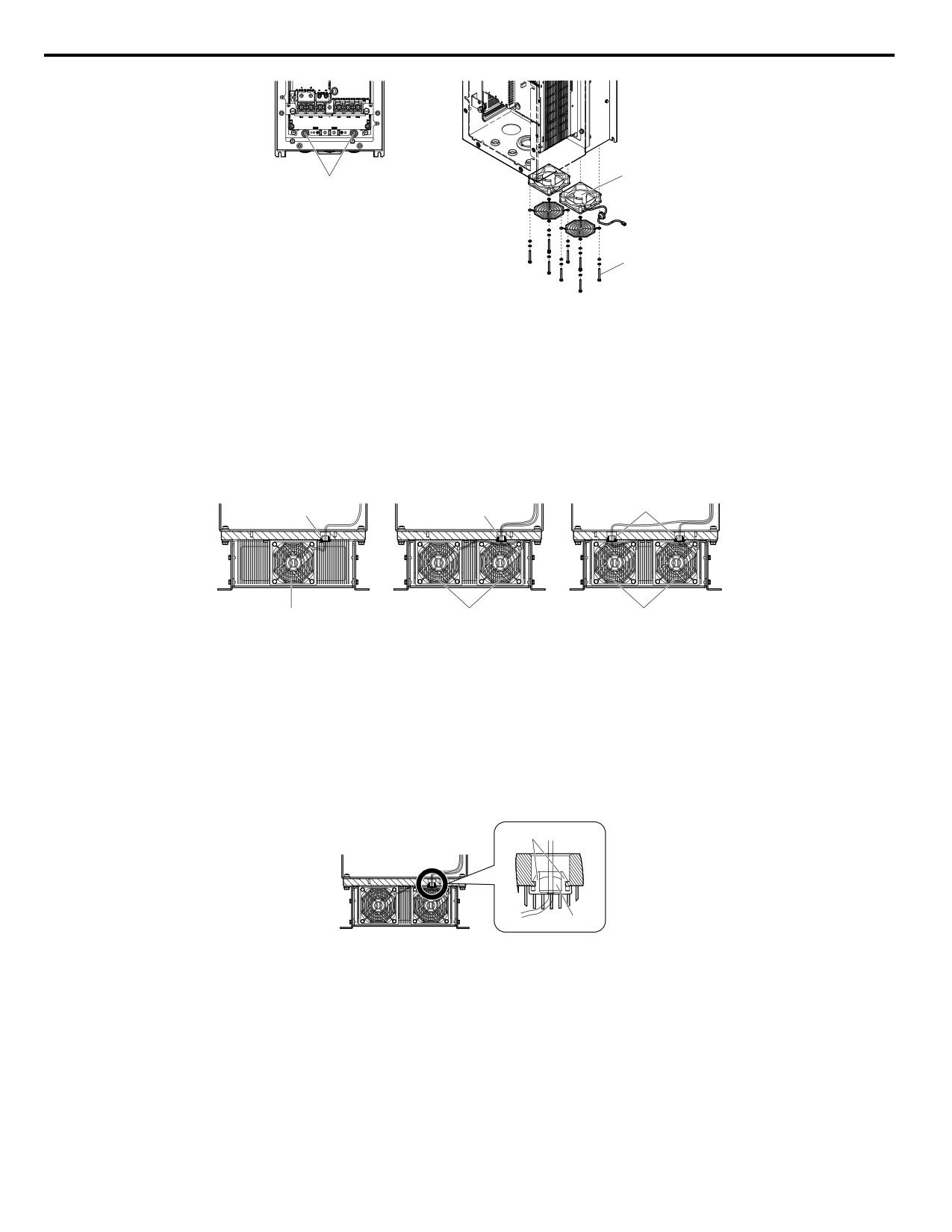
7.4 Drive Cooling Fans
Label
Rubber bushing
Push the rubber bushing
out of the wiring holes
Bolt 7 mm
Figure 7.10 Removing the External Fan
n Installing the External Fan
The external fan installation procedure differs by drive model. Refer to Figure 7.11 for the different fan configurations.
NOTICE: Install the fan with the label facing the toward the inside of the drive. The fan may be damaged if it is facing the wrong direction.
2V0030G to 2V0056G
4V0038G
2V0069G
4V0018G to 4V0031G
A
A
A
B
B
B
A - Conduit hole
B - Fan unit
Figure 7.11 External Fans and Conduit Holes
1. Place the rubber bushing for the fan into the heatsink holes.
NOTICE: Ensure that all bushings fit securely into place. Loose rubber bushings may allow water and dust to enter the drive.
2. Route the fan wiring through the rubber bushing.
3. Plug the fan connector back in.
4. Fill the wiring hole in the rubber grommet to a minimum depth of 9.7 mm (0.38 in.) with RTV sealant (KE-3494) specified
in Table 7.5.
A
B
Figure 7.12 Fastening the Rubber Bushing in Model 4V0038G
5. Install the fan guard onto the fan.
6. Replace the fan into its original position and fasten the fan into place.
300
7.5 Drive Replacement
7.5
Drive Replacement
u Serviceable Parts
The drive contains few serviceable parts. The following parts are considered replacement parts on the drive:
• Main control board and I/O Terminal board I/O PCBs.
• Cooling fan(s)
• Front cover
Replace the drive if the main power circuitry is damaged. Contact your local Yaskawa representative before replacing parts
if the drive is still under warranty. Yaskawa reserves the right to replace or repair the drive according to Yaskawa warranty
policy.
On IP66/NEMA 4X, UL Type 4X enclosure drives, replace the entire unit (drive, enclosure, and heatsink) in the event that
any single part becomes damaged. The drive, waterproof/dustproof enclosure, and heatsink are constructed as a single piece,
and it is not possible to replace the drive separately from the protective enclosure.
WARNING! Electrical Shock Hazard. Do not connect or disconnect wiring while the power is on. Failure to comply can result in serious
personal injury. Before servicing the drive, disconnect all power to the equipment. The internal capacitor remains charged even after the
power supply is turned off. The charge indicator LED will extinguish when the DC bus voltage is below 50 Vdc. To prevent electric shock,
wait at least five minutes after all indicators are OFF and measure the DC bus voltage level to confirm safe level.
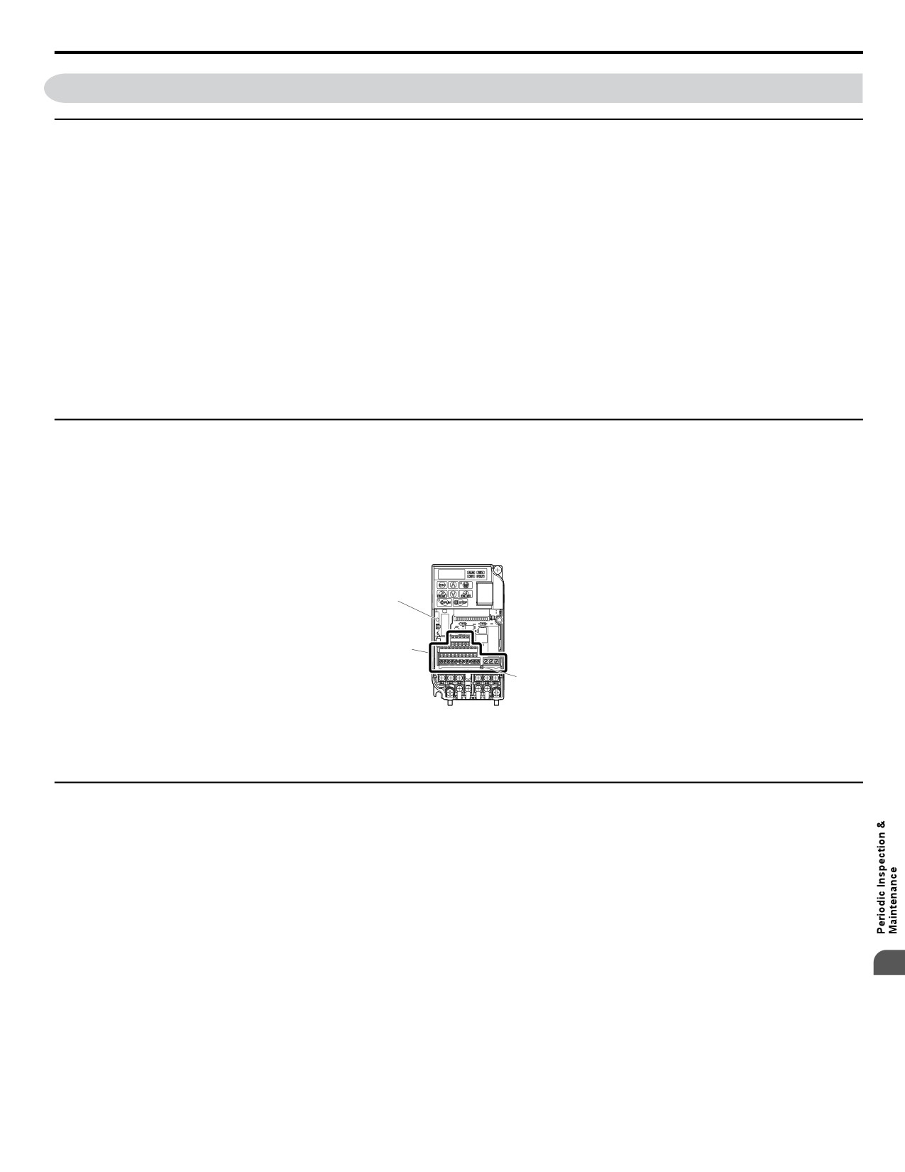
u Terminal Board Overview
The drive has a modular I/O terminal block that facilitates quick drive replacement. The terminal board contains on-board
memory that stores all drive parameter settings and allows the parameters to be saved and transferred to the replacement drive
by disconnecting the terminal board from the damaged drive then reconnecting the terminal board to the replacement drive.
There is no need to manually reprogram the replacement drive.
Note:
When transferring the removable terminal block with backup memory to a drive with a different voltage class or different output capacity,
set A1-03 to 2220 to initialize the drive after installing the terminal block.
A
C
B
A - Charge LED
C - Removable Terminal Board
B - Terminal Board Locking Pin
Figure 7.13 Terminal Board
u Dismantling the Removable Terminal Block
WARNING! Electrical Shock Hazard. Never connect or disconnect wiring, remove connectors or option cards, or replace the cooling fan
while the power is on. Failure to comply may result in serious injury. Before servicing, disconnect all power to the equipment. The internal
capacitor remains charged even after the power supply is turned off.
WARNING! Electrical Shock Hazard. Do not allow unqualified personnel to perform work on the drive. Failure to comply could result in
serious injury. Installation, maintenance, inspection and servicing must be performed only by authorized personnel familiar with installation,
adjustment and maintenance of AC drives.
NOTICE: Damage to Equipment. Observe proper electrostatic discharge procedures (ESD) when handling the drive and circuit boards.
Failure to comply may result in ESD damage to the drive circuitry.
1. Loosen the screw on the front of the drive and remove the front cover.
7
301
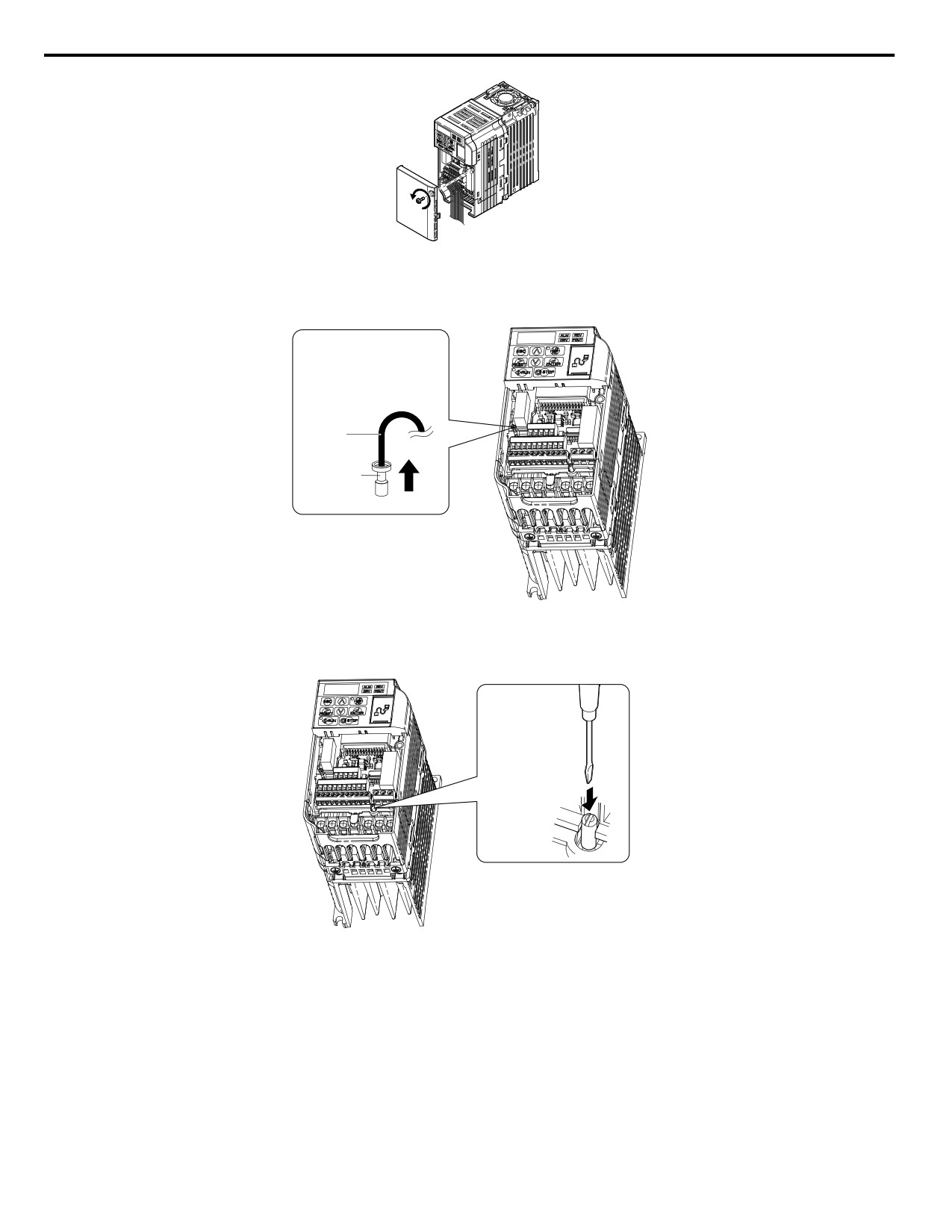
7.5 Drive Replacement
Figure 7.14 Remove the Front Cover
2. Pull the pin on the ground terminal out of the removable terminal block.
Pull out the
ground terminal
pin in the direction
indicated by
the arrow.
Cable
Terminal
Figure 7.15 Pull Out the Ground Terminal
3. Push down the installation pin on the terminal board with a screwdriver
Push down
the terminal
board locking
pin with a
screwdriver.
Figure 7.16 Depress the Plastic Tab
4. While holding down the locking pin from step 3, slide the removable terminal block in the direction of the arrows in
Figure 7.17.
302
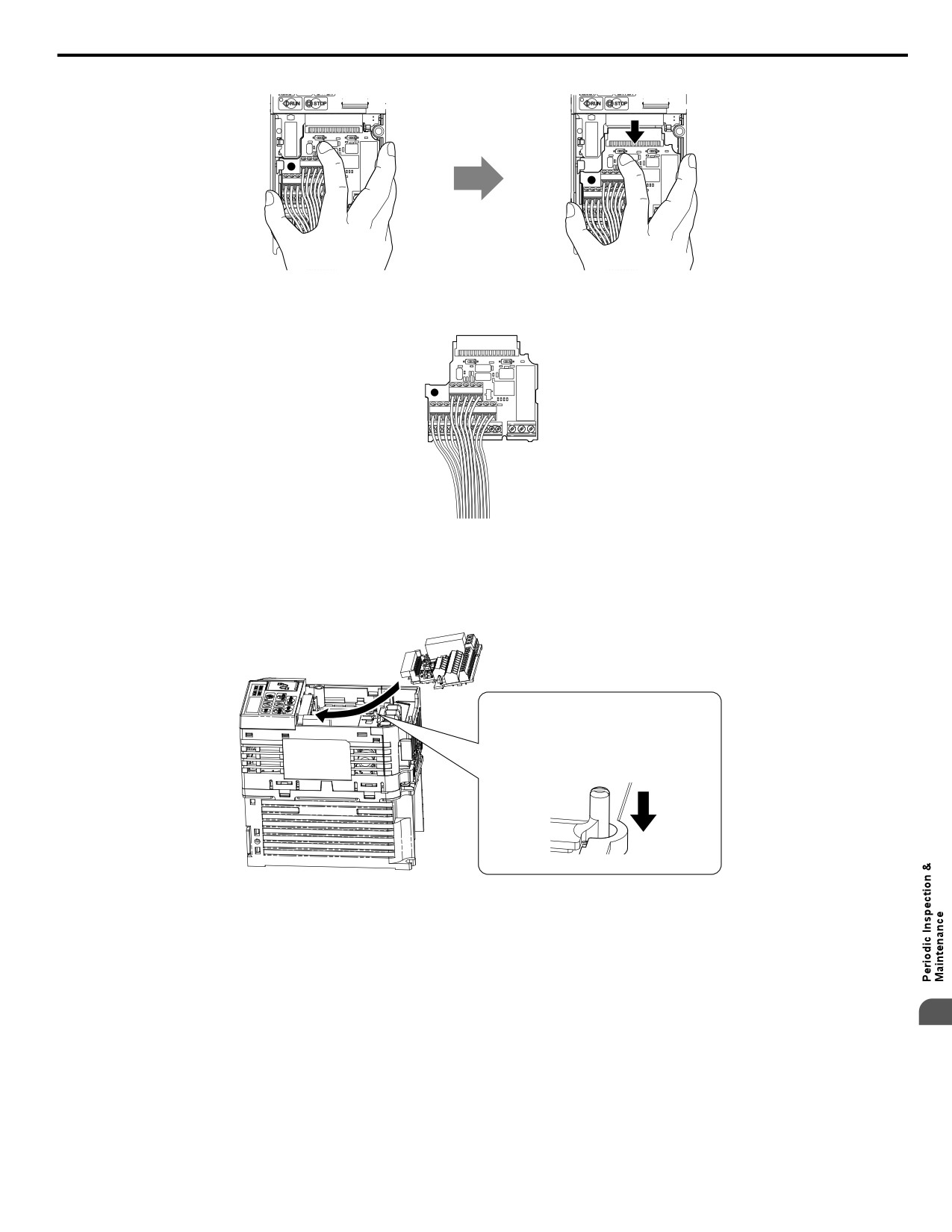
7.5 Drive Replacement
Figure 7.17 Remove the Terminal Board
Figure 7.18 Removable Terminal Board Disconnected from the Drive
n Reinstalling the Terminal Board
1. Reinstall the removable terminal block on the drive according to Figure 7.19.
Place the terminal board below the
guide tracks in the plastic case of the
drive. Then push it gently down and
slide it toward the keypad until the
locking pin clicks into place.
Figure 7.19 Terminal Board Reinstallation
2. Ensure the terminal block is firmly fastened to the connector.
7
303
7.5 Drive Replacement
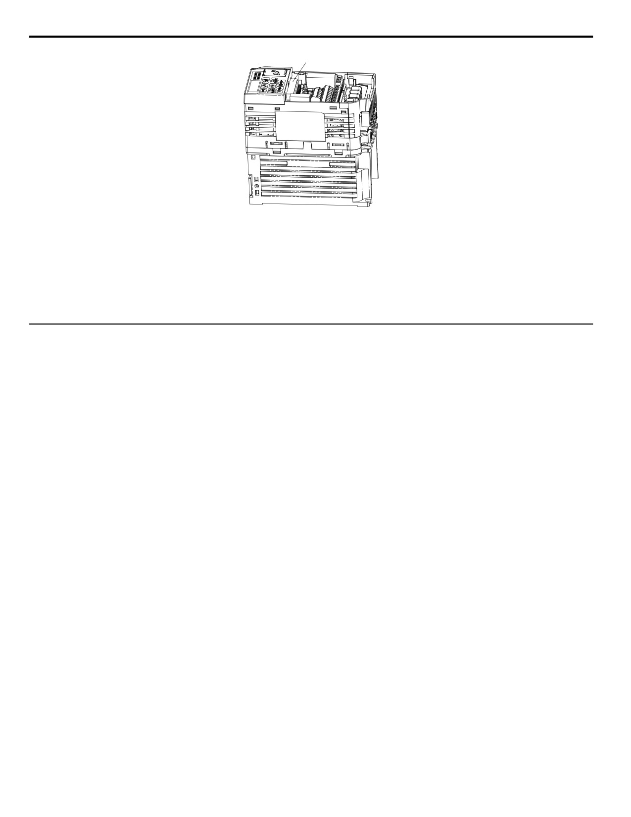
Connector
Figure 7.20 Terminal Board Reinstalled
3. Put the lower cover and the terminal cover back in place.
4. After replacing the drive, check the drive unit selection setting in o2-04. Refer to Defaults by Drive Model on page
377 for more information.
5. An oPE04 error may occur when replacing the drive or the removable terminal block. If the data saved to the terminal
block is compatible, set A1-03 to 5550 to write the parameter settings stored in the terminal block to the new drive.
Reset the appropriate maintenance monitors using parameters o4-01 to o4-13.
u Details on Terminal Board (TB) or Control Board (CNT) Replacement
The drive Terminal Board retains drive parameter settings to significantly improve the ease of drive replacement. Refer to
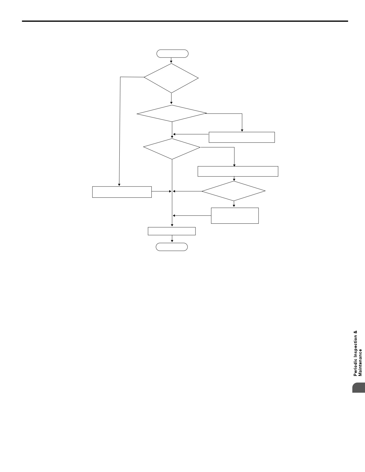
Troubleshooting Terminal Board or Control Board Replacement on page 305 for a flowchart to assist in board replacement.
When replacing the drive, or changing the Control Board or Terminal Board, the following error codes may be encountered
upon application of power:
• oPE04 Drive parameter settings need to be initialized or uploaded from the TB.
• CPF06 Drive specification does not match the replaced drive.
• oPE01 Drive parameter o2-04 kVA requires setting.
Procedural Notes:
1. When replacing the drive, control board or terminal board, make sure to confirm the kVA setting, parameter o2-04 is
correct upon initial power-up.
2. Perform an initialization (via parameter A1-03) to obtain the desired parameter settings.
3. In cases where a previously programmed terminal board is retained, initializing the drive with a setting of A1-03 = 5550
may be desired to program the drive with previously programmed settings (settings used prior to replacing the drive or
control board).
304
7.5
Drive Replacement
Troubleshooting Fault Codes at
Terminal Board (TB) or Control Board (CNT) Replacement
START
YES
“CPF06” Fault is
displayed upon drive
replacement
Note: Drive kVA Setting o2-04 = “FF”
NO
inside a new Terminal Board
YES
Fault “oPE01”
NO
Set parameter o2-04 to match drive
nameplate rating
Fault “oPE04”
YES
NO
Fault “oPE04” drive parameter settings need
to be initialized or uploaded from the TB
Initialize the drive using
Initialize the drive using
Parameter A1-03 = 2220 or 3330
parameter A1-03
Set value = 2220
or 3330
Set value = 5550
Parameter setting values
are copied
TB to CNT
Ready
END
Figure 7.21 Troubleshooting Terminal Board or Control Board Replacement
7
305
7.5 Drive Replacement
This Page Intentionally Blank
306
Appendix: A
Specifications
A.1
POWER RATINGS
308
A.2
DRIVE SPECIFICATIONS
311
A.3
DRIVE WATT LOSS DATA
313
A.4
DRIVE DERATING DATA
314
307
A.1 Power Ratings
A.1
Power Ratings
u Single-Phase 200 V Class Drives
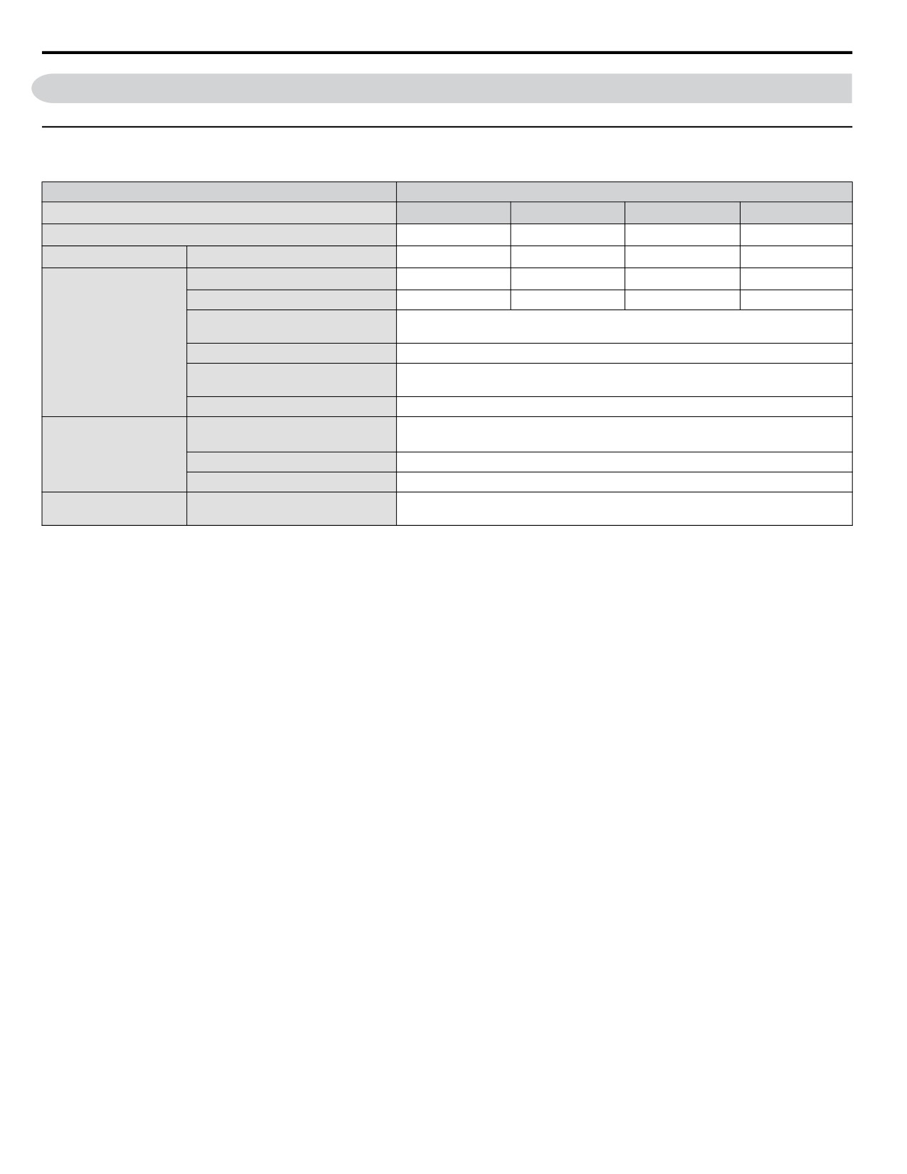
Table A.1 Single-Phase 200 V Class Power Ratings
Item
Specification
Single-Phase Drive Model <1>
BV0006
BV0010
BV0012
BV0018
Maximum Motor Size Allowed kW (HP) <2>
1.1 (1)
2.2 (3)
3.0 (3)
3.7 (5)
Input
Input Current (A) <3>
13.8
20.2
24.0
35.0
Rated Output Capacity (kVA) <4>
2.3
3.7
4.6
6.7
Output Current (A)
6.0
9.6
12.0
17.5
120% of rated output current for 1 minute
Overload Tolerance
(Derating may be required for applications that start and stop frequently)
Output
Carrier Frequency
User-adjustable 2 to 15 kHz
Single-phase power: 200 to 240 V
Max Output Voltage (V)
(both proportional to input voltage)
Max Output Frequency (Hz)
400 Hz (user-adjustable)
Rated Voltage
Single-phase power: 200 to 240 V 50/60 Hz
Rated Frequency
DC power supply: 270 to 340 V <5>
Power Supply
Allowable Voltage Fluctuation
-15 to 10%
Allowable Frequency Fluctuation
±5%
Harmonic Corrective
DC Link Choke
Optional
Actions
<1> Drives with single-phase power supply input will output three-phase power and cannot run a single-phase motor.
<2> The motor capacity (HP) refers to a NEC rated 4-pole motor. The rated output current of the drive output amps should be equal to or greater than
the motor rated current.
<3> Input current rating varies depending on the power supply transformer, input reactor, wiring connections, and power supply impedance.
<4> Rated motor capacity is calculated with a rated output voltage of 230 V.
<5> DC is not available for UL standards.
308
A.1 Power Ratings
u Three-Phase 200 V Class Drives
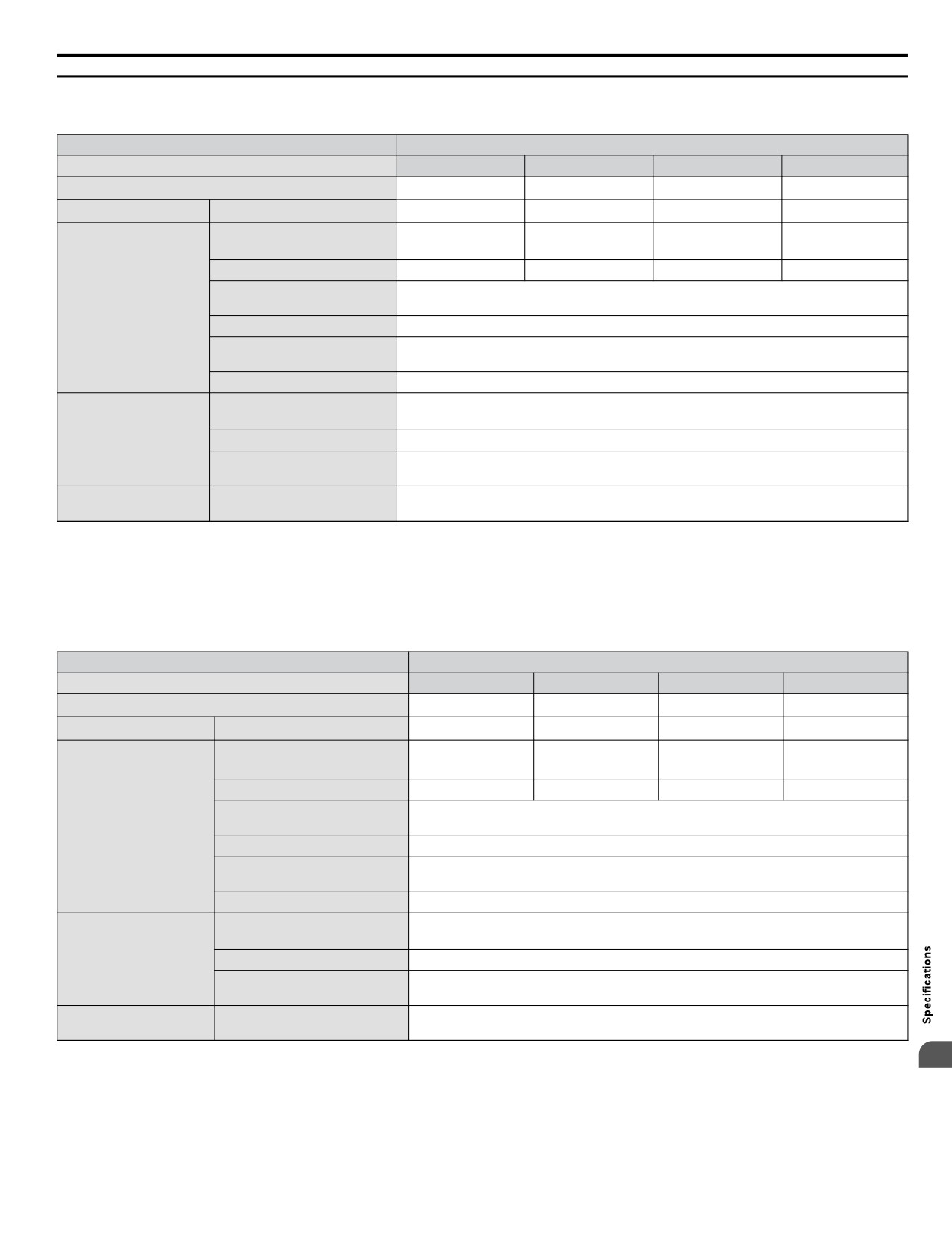
Table A.2 Three-Phase 200 V Class Power Ratings
Item
Specification
Three-Phase Drive Model
2V0006
2V0010
2V0012
2V0020
Maximum Motor Size Allowed kW (HP) <1>
1.1
(1.5)
2.2 (3)
3.0 (3)
5.5 (5)
Input
Input Current (A) <2>
7.3
10.8
13.9
24.0
Rated Output Capacity (kVA)
<3>
2.3
3.7
4.6
7.5
Output Current (A)
6.0
9.6
12.0
19.6
120% of rated output current for 1 minute
Overload Tolerance
Output
(Derating may be required for applications that start and stop frequently)
Carrier Frequency
User-adjustable 2 to 15 kHz
Three-phase power: 200 to 240 V
Max Output Voltage (V)
(proportional to input voltage)
Max Output Frequency (Hz)
400 Hz (user-adjustable)
Rated Voltage
Three-phase power: 200 to 240 V 50/60 Hz
Rated Frequency
DC power supply: 270 to 340 V <4>
Power Supply
Allowable Voltage Fluctuation
-15 to 10%
Allowable Frequency
±5%
Fluctuation
Harmonic Corrective
DC Link Choke
Optional
Actions
<1>
The motor capacity (HP) refers to a NEC rated 4-pole motor. The rated output current of the drive output amps should be equal to or greater than
the motor rated current.
<2>
Input current rating varies depending on the power supply transformer, input reactor, wiring connections, and power supply impedance.
<3>
Rated motor capacity is calculated with a rated output voltage of 230 V.
<4>
DC is not available for UL standards.
Table A.3 Three-Phase 200 V Class Power Ratings Continued
Item
Specification
Three-Phase Model
2V0030
2V0040
2V0056
2V0069
Maximum Motor Size Allowed kW (HP) <1>
7.5 (10)
11 (10)
15 (20)
18.5 (25)
Input
Input Current (A) <2>
37.0
52.0
68.0
80.0
Rated Output Capacity (kVA)
11.4
15.2
21.3
26.3
<3>
Output Current (A)
30.0
40.0
56.0
69.0
120% of rated output current for 1 minute
Overload Tolerance
Output
(Derating may be required for applications that start and stop frequently)
Carrier Frequency
User-adjustable 2 to 15 kHz
Three-phase power: 200 to 240 V
Max Output Voltage (V)
(proportional to input voltage)
Max Output Frequency (Hz)
400 Hz (user-adjustable)
Rated Voltage
Three-phase power: 200 to 240 V 50/60 Hz
Rated Frequency
DC power supply: 270 to 340 V <4>
Power Supply
Allowable Voltage Fluctuation
-15 to 10%
Allowable Frequency
±5%
Fluctuation
Harmonic Corrective
DC Link Choke
Optional
Actions
<1> The motor capacity (HP) refers to a NEC rated 4-pole motor. The rated output current of the drive output amps should be equal to or greater than
A
the motor rated current.
<2> Input current rating varies depending on the power supply transformer, input reactor, wiring connections, and power supply impedance.
<3> Rated motor capacity is calculated with a rated output voltage of 230 V.
<4> DC is not available for UL standards.
309
A.1 Power Ratings
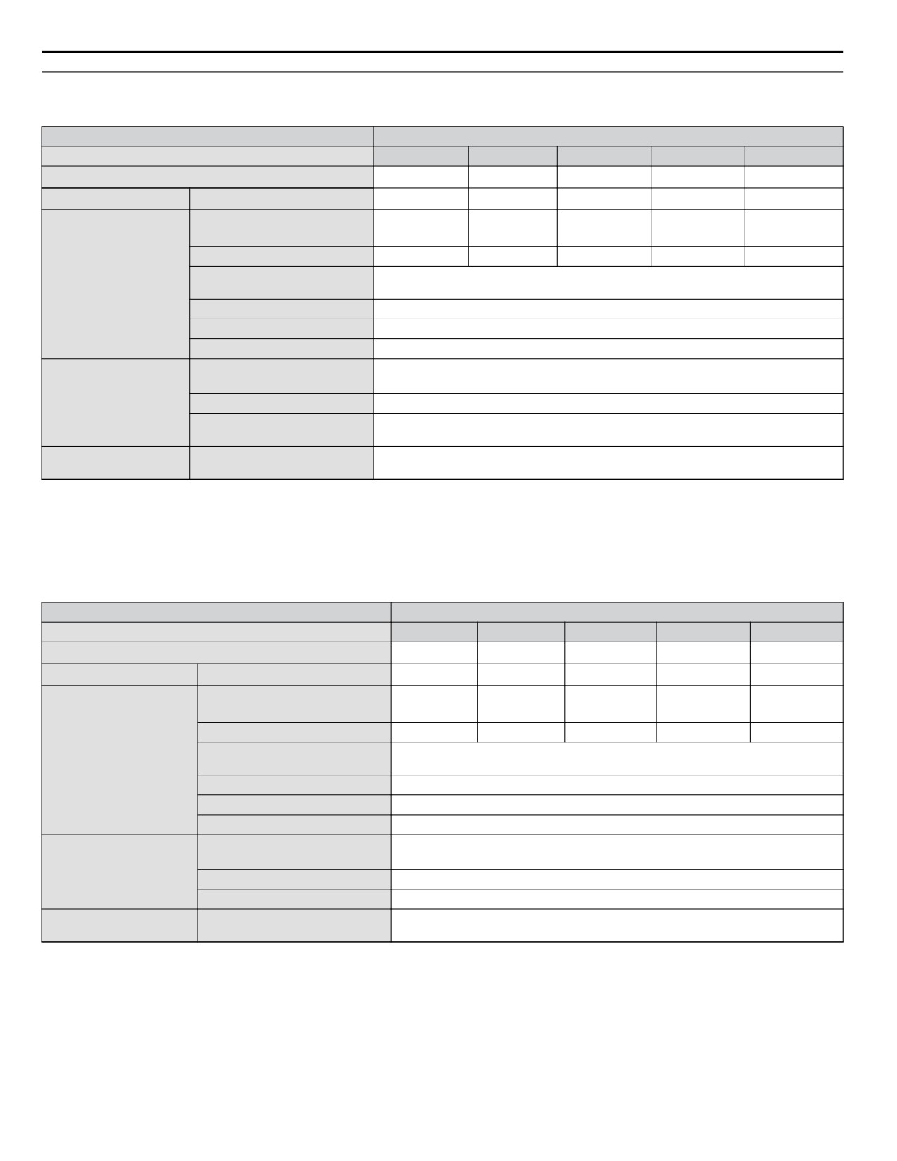
u Three-Phase 400 V Class Drives
Table A.4 Three-Phase 400 V Class Power Ratings
Item
Specification
Three-Phase Model
4V0002
4V0004
4V0005
4V0007
4V0009
Maximum Applicable Motor Capacity kW (HP) <1>
0.75
(1.0)
1.5 (2)
2.2 (3)
3.0 (3)
3.7 (5)
Input
Input Current (A) <2>
2.1
4.3
5.9
8.1
9.4
Rated Output Capacity (kVA)
1.6
3.1
4.1
5.3
6.7
<3>
Output Current (A)
2.1
4.1
5.4
6.9
8.8
120% of rated output current for 60 s
Output
Overload Tolerance
(Derating may be required for applications that start and stop frequently)
Carrier Frequency
User-adjustable 2 to 15 kHz
Max Output Voltage (V)
Three-phase power: 380 to 480 V (proportional to input voltage)
Max Output Frequency (Hz)
400 Hz (user-adjustable)
Rated Voltage
Three-phase power: 380 to 480 V 50/60 Hz
Rated Frequency
DC power supply: 510 to 680 V <4>
Power Supply
Allowable Voltage Fluctuation
-15 to 10%
Allowable Frequency
±5%
Fluctuation
Harmonic Corrective
DC Link Choke
Optional
Actions
<1> The motor capacity (HP) refers to a NEC 4-pole motor. The rated output current of the drive output amps should be equal to or greater than the
motor rated current.
<2> Input current rating varies depending on the power supply transformer, input reactor, wiring conditions, and power supply impedance.
<3> Rated motor capacity is calculated with a rated output voltage of 460 V.
<4> DC is not available for UL standards.
Table A.5 Three-Phase 400 V Class Power Ratings Continued
Item
Specification
Three-Phase Model
4V0011
4V0018
4V0023
4V0031
4V0038
Maximum Applicable Motor Capacity kW (HP) <1>
5.5
(7.5)
7.5 (10)
11 (15)
15 (20)
18.5 (25)
Input
Input Current (A)
<2>
14.0
20.0
24.0
38.0
44.0
Rated Output Capacity (kVA)
8.5
13.3
17.5
23.6
29.0
<3>
Output Current (A)
11.1
17.5
23.0
31.0
38.0
120% of rated output current for 60 s
Output
Overload Tolerance
(Derating may be required for applications that start and stop frequently)
Carrier Frequency
User-adjustable 2 to 15 kHz
Max Output Voltage (V)
Three-phase power: 380 to 480 V (proportional to input voltage)
Max Output Frequency (Hz)
400 Hz (user-adjustable)
Rated Voltage
Three-phase power: 380 to 480 V 50/60 Hz
Rated Frequency
DC power supply: 510 to 680 V <4>
Power Supply
Allowable Voltage Fluctuation
-15 to 10%
Allowable Frequency Fluctuation
±5%
Harmonic Corrective
DC Link Choke
Optional
Actions
<1> The motor capacity (HP) refers to a NEC 4-pole motor. The rated output current of the drive output amps should be equal to or greater than the
motor rated current.
<2> Input current rating varies depending on the power supply transformer, input reactor, wiring conditions, and power supply impedance.
<3> Rated motor capacity is calculated with a rated output voltage of 460 V.
<4> DC is not available for UL standards.
310
A.2 Drive Specifications
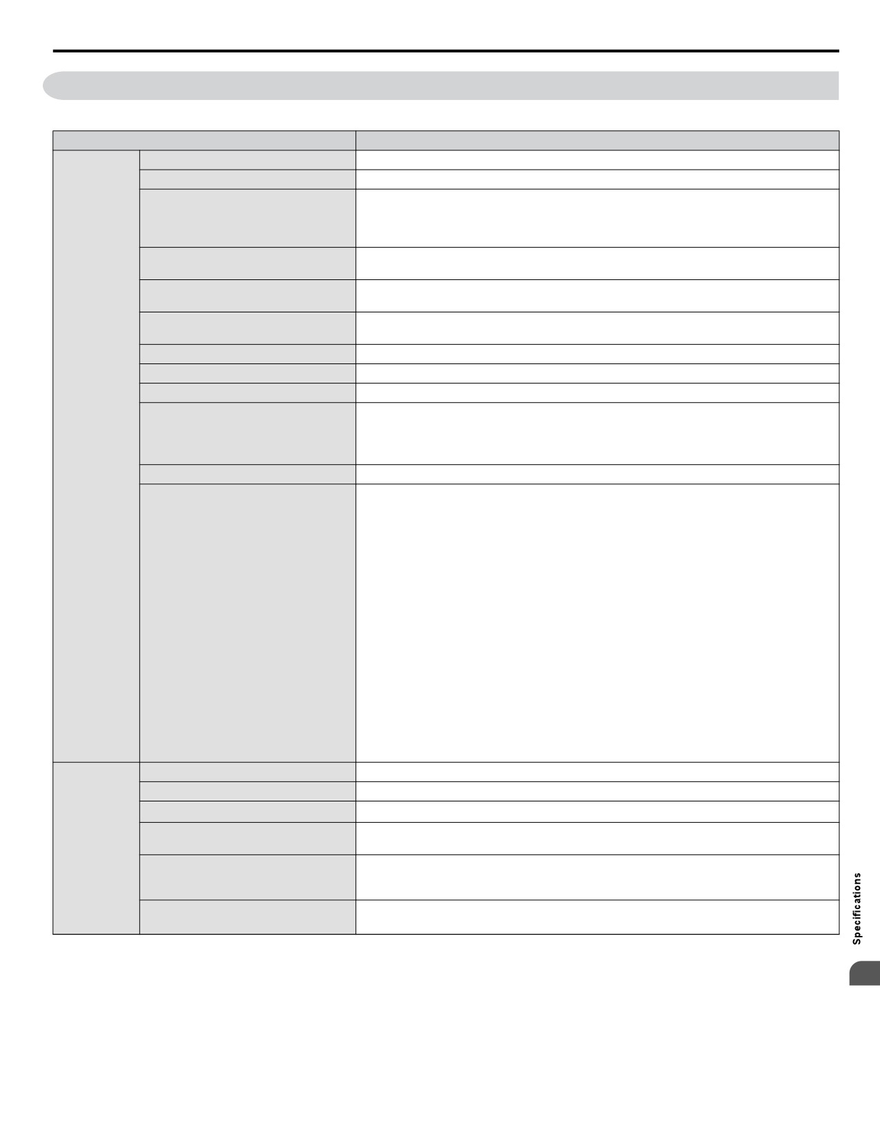
A.2
Drive Specifications
Note:
For optimum performance life of the drive, install the drive in an environment that meets the required specifications.
Item
Specification
Control Method
V/f Control (V/f)
Frequency Control Range
0.01 to 400 Hz
Digital input: within ±0.01% of the max output frequency
(-10 to +50 °C)
Frequency Accuracy
Analog input: within ±0.5% of the max output frequency
(25 °C ±10 °C)
Digital inputs: 0.01 Hz
Frequency Setting Resolution
Analog inputs: 1/1000 of maximum output frequency
Output Frequency Calculation
1/220 x Maximum output frequency (E1-04)
Resolution
Main frequency reference: 0 to +10 Vdc (20 kΩ), 4 to 20 mA (250 Ω), 0 to 20 mA (250 Ω)
Frequency Setting Signal
Main speed reference: Pulse Train Input (max 32 kHz)
Starting Torque
V/f: 150% at 3 Hz
Speed Control Range
1:40 (V/f Control)
Accel/Decel Time
0.00 to 6000.0 s (allows four separate settings for accel and decel)
Instantaneous Average Decel Torque <1> : 0.1/0.2 kW: over 150%, 0.4/0.75 kW: over 100%,
1.5 kW: over 50%, 2.2 kW and above: over 20%
Braking Torque
Control
Continuous Regen Torque: 20%,
Character-
125% with a Braking Resistor Unit <2> : (10% ED) 10 s with an internal braking resistor.
istics
V/f Characteristics
Preset V/f patterns and user-set program available.
Momentary Power Loss Ride-Thru
Speed Search
Over/Undertorque Detection
Multi-Step Speed (17 steps max)
Accel/Decel Time Switch
S-Curve Accel/Decel,
2-Wire/3-Wire Sequence
Stationary Auto-Tuning of Line-to-Line Resistance
Dwell
Cooling Fan ON/OFF
Functions
Slip Compensation
Torque Compensation
Jump Frequencies (reference dead band)
Frequency Reference Upper/Lower Limit
DC Injection Braking (start and stop)
PID Control (with Sleep Function)
MEMOBUS/Modbus (RS-485/RS-422 Max 115.2 kbps)
Fault Reset
Parameter Copy
Fault Restart
Removable Terminals with Parameter Backup Function
Motor Protection
Motor overheat protection via output current sensor
Overcurrent Protection
Drives stops when output exceeds 170% of the rated current
Overload Protection
Drive stops when output current is 120% rated current for 60 sec. <3>
200 V Class: Stops when DC bus voltage exceeds approx. 410 V
Protection
Overvoltage Specification
400 V Class: Stops when DC bus voltage exceeds approx. 820 V
Functions
Drive stops when DC bus voltage falls below the levels indicated:
Low Voltage Protection
190 V (3-phase 200 V), 160 V (single-phase 200 V), 380 V (3-phase 400 V), 350 V (3-phase
380 V)
3 selections available: Ride-Thru disabled (stops after 15 ms), time base of 0.5 s, and continue
Momentary Power Loss Ride-Thru
running as long as the drive control board is powered up. <4>
A
311
A.2 Drive Specifications
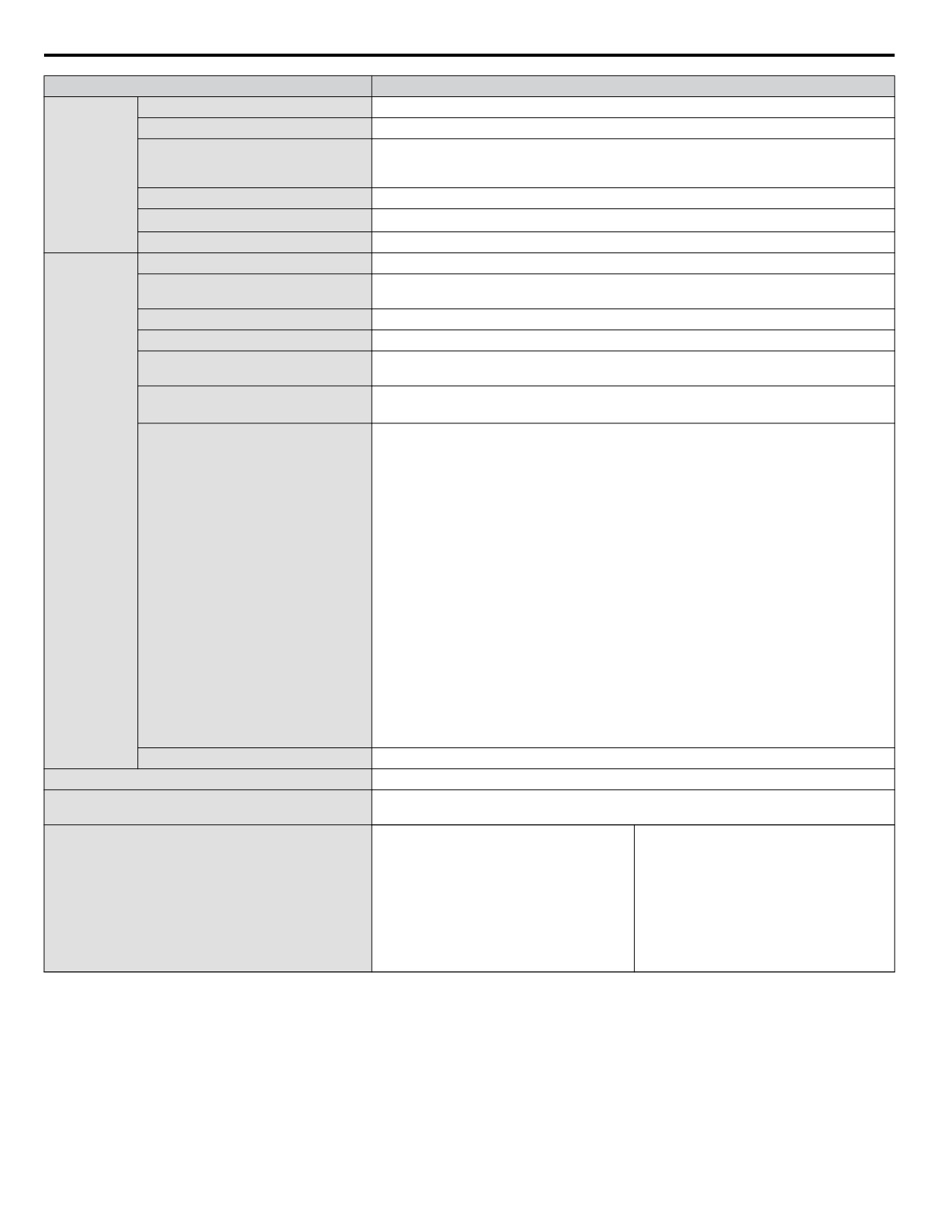
Item
Specification
Heatsink Overheat Protection
Protected by thermistor
Braking Resistor Overheat Protection
Overheat input signal for braking resistor (Optional ERF-type, 3% ED)
Stall prevention is available during acceleration, deceleration, and during run. Separate
Stall Prevention
settings for each type of stall prevention determine the current level at which stall prevention
Protection
is triggered.
Functions
Cooling Fan Failure Protection
Circuit protection (“fan-lock” sensor)
Ground Fault Protection
Electronic circuit protection <5>
DC Bus Charge LED
Remains lit until DC bus voltage falls below 50 V
Storage/Installation Area
Indoors
IP20/NEMA 1, UL Type 1 enclosure: -10 °C to +40 °C (14 °F to 104 °F)
Ambient Temperature
IP66/NEMA 4X, UL Type 4X enclosure: -10 °C to +40 °C (14 °F to 104 °F)
Humidity
95% RH or less with no condensation
Storage Temperature
-20 to +60 °C (-4 to +140 °F) allowed for short-term transport of the product
Up to 1000 meters without derating; up to 3000 meters with output current and voltage
Altitude
derating.
2
10 to 20 Hz: 9.8 m/s
Shock, Impact
20 to 55 Hz: 5.9 m/s2
Install the drive in an area free from:
• oil mist and dust
• metal shavings, oil, water or other foreign materials
• radioactive materials
Environment
• combustible materials (e.g., wood)
• harmful gases and liquids
• excessive vibration
• chlorides
Surrounding Area
• direct sunlight
For IP66/NEMA 4X, UL Type 4X enclosure drives, install the drive in an environment suitable
for IP66/NEMA 4X, UL Type 4X enclosures:
• NEMA 4X, UL Type 4X - Enclosures constructed for either indoor or outdoor use to
provide a degree of protection to personnel against incidental contact with the enclosed
equipment; to provide a degree of protection against falling dirt, rain, sleet, snow,
windblown dust, splashing water, hose-directed water, and corrosion; and that will be
undamaged by the external formation of ice on the enclosure.
• IP66 - Dust-tight enclosures to not allow any dust to penetrate. The enclosure guards the
drive against powerful jetting water sprayed from any direction and is protected against
access to hazardous parts with a wire.
Orientation
Install the drive vertically to maintain maximum cooling effects
Standards
cULus
IP20/NEMA 1, UL Type 1
Protective Enclosure
IP66/NEMA 4X, UL Type 4X
BV0006G and BV0010G: self-cooled
BV0012G: internal cooling fan
2V0006G to 2V0012G: self-cooled
BV0006F: self-cooled
2V0020G: internal cooling fan
BV0010F to BV0018F: cooling fan
2V0030G to 2V0069G: internal and external
Cooling Method
2V0006F to 2V0069F: cooling fan
cooling fans
4V0002F to 4V0004F: self-cooled
4V0002G to 4V0005G: self-cooled
4V0005F to 4V0038F: cooling fan
4V0007G to 4V0011G: internal cooling fan
4V0018G to 4V0038G: internal and external
cooling fans
<1>
Instantaneous average deceleration torque refers to the torque required to decelerate the motor (uncoupled from the load) from the rated motor speed
down to zero in the shortest time.
<2>
Ensure that Stall Prevention Selection during Deceleration is disabled (L3-04 = 0) or set to 3 when using a braking resistor or the Braking Resistor
Unit. The default setting for the stall prevention function will interfere with the braking resistor.
<3>
Overload protection may be triggered when operating with 150% of the rated output current if the output frequency is less than 6 Hz.
<4>
A Momentary Power Loss Ride-Thru Unit is required for 200/400 V class drives 7.5 kW and less if the application needs to continue running during
a momentary power loss up to 2 seconds.
<5>
Ground protection cannot be provided under the following circumstances when a ground fault is likely in the motor windings during run: Low
ground resistance for the motor cable and terminal block; low ground resistance for the motor cable and terminal block; or the drive is powered up
from a ground short.
312
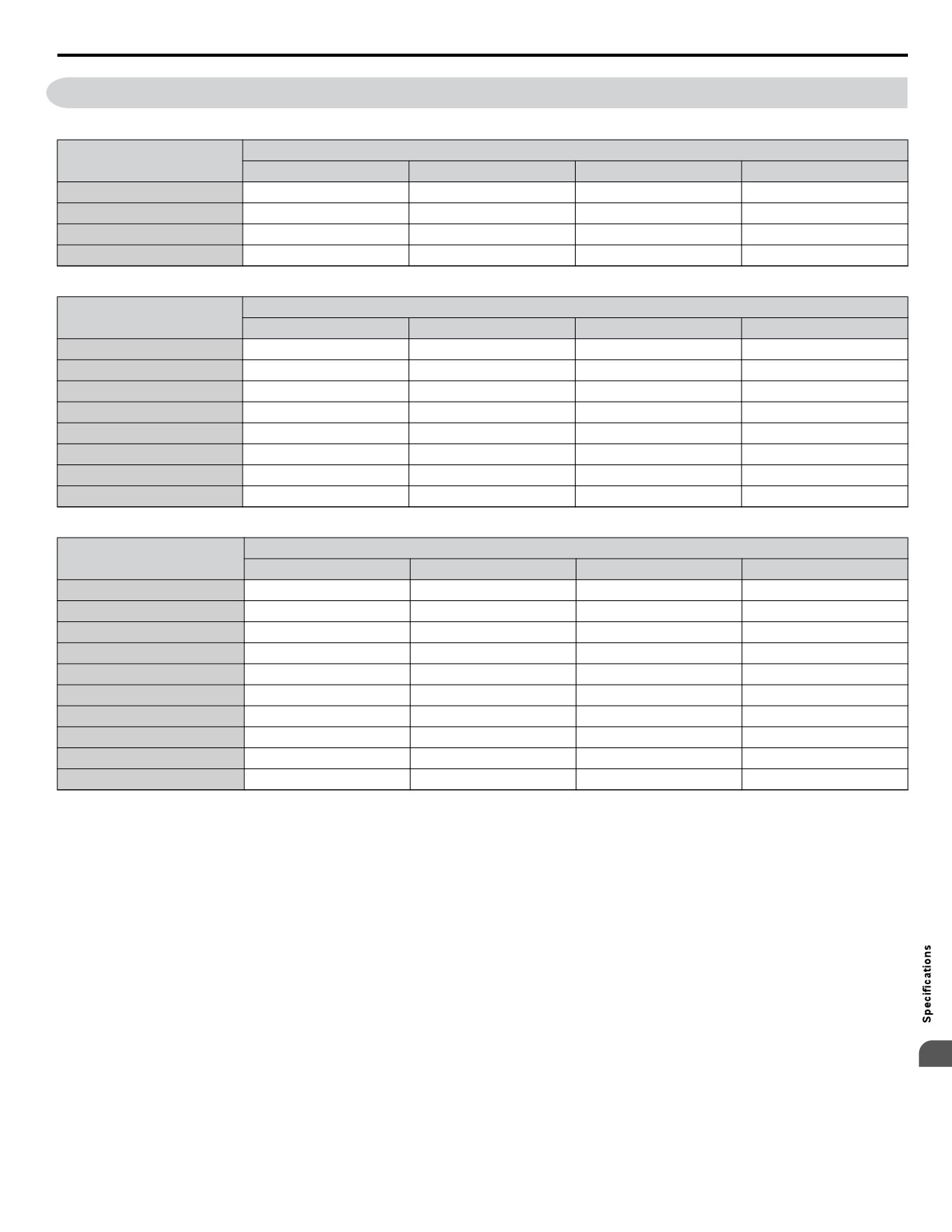
A.3
Drive Watt Loss Data
A.3
Drive Watt Loss Data
Table A.6 Watt Loss 200 V Class Single-Phase Models
Normal Duty (Swing PWM equal 2 kHz)
Drive Model
Rated Amps (A)
Heatsink Loss (W)
Interior Unit Loss (W)
Total Loss (W)
BV0006
6.0
30.1
19.4
49.5
BV0010
9.6
51.7
29.8
81.4
BV0012
12.0
61.3
37.1
98.4
BV0018
17.5
110.5
51.4
161.9
Table A.7 Watt Loss 200 V Class Three-Phase Models
Normal Duty (Swing PWM equal 2 kHz)
Drive Model
Rated Amps (A)
Heatsink Loss (W)
Interior Unit Loss (W)
Total Loss (W)
2V0006
6.0
27.5
17.2
44.7
2V0010
9.6
51.7
25.8
77.5
2V0012
12.0
61.3
30.4
91.7
2V0020
19.6
98.7
46.3
145.0
2V0030
30.0
246.4
88.9
335.3
2V0040
40.0
266.7
112.8
379.6
2V0056
56.0
357.9
151.8
509.7
2V0069
69.0
461.7
184.5
646.2
Table A.8 Watt Loss 400 V Class Three-Phase Models
Normal Duty (Swing PWM equal 2 kHz)
Drive Model
Rated Amps (A)
Heatsink Loss (W)
Interior Unit Loss (W)
Total Loss (W)
4V0002
2.1
18.5
13.9
32.4
4V0004
4.1
30.5
16.8
47.3
4V0005
5.4
44.5
21.8
66.3
4V0007
6.9
58.5
28.4
86.9
4V0009
8.8
63.7
31.4
95.1
4V0011
11.1
81.7
46.0
127.7
4V0018
17.5
181.2
80.1
261.3
4V0023
23.0
213.4
107.7
321.1
4V0031
31.0
287.5
146.1
433.6
4V0038
38.0
319.2
155.8
475.0
A
313
A.4 Drive Derating Data
A.4
Drive Derating Data
The drive can be operated at above the rated temperature, altitude, and default carrier frequency by derating the drive capacity.
u Single-Phase Derating
iQpump Micro drives are compatible for use with both three-phase and single-phase input power supplies. The drive output
to the motor is always three-phase, regardless of number of input phases.
Output capacity to the motor is derated when using single-phase input power and the drive firmware includes protection for
single-phase input applications. This protection is enabled by default. Disabling this protection for single-phase input
applications can void warranty and result in premature failure.
Selection of larger models always results in greater output capacity to the motor when supplying the drive with three-phase
input power. However, the selection of larger models does not always yield greater output capacity when using the drive with
single-phase input power.
Several factors affect the amount of derated drive output capacity when single-phase input power is supplied to the drive:
• Single-phase input voltage level
• Motor voltage rating
• Amount of input impedance.
The tables in this section assist in model selection by considering factors that affect the amount of derating in single-phase
input power applications.
n Single-Phase Input Sizing
The rated output current listed in the tables allows for a 120% overload for 60 seconds. Contact Yaskawa if assistance is needed
in selecting drive models with higher overload requirements. Adding more impedance than is specified will degrade
performance.
Table A.9 240 V Single-Phase Input (-5% to +10%)
Without Input Reactor
With Input Reactor
Drive Model
Rated
Max
Rated
Max
Rated Input
Yaskawa Reactor Part
Rated Input
Output
Applicable
Output
Applicable
Current (A)
Number
Current (A)
Current (A)
Motor (HP)
Current (A)
Motor (HP)
2V0006
7.3
4.9
1.0
URX000303
7.3
4.9
1.0
2V0010
10.8
6.8
1.5
URX000307
10.8
6.8
1.5
2V0012
13.9
7.5
2.0
URX000311
13.9
7.5
2.0
2V0020
24.0
9.7
2.0
URX000319
24.0
12.3
3.0
2V0030
37.0
7.5
2.0
URX000326
37.0
15.2
3.0
2V0040
52.0
16.7
5.0
URX000329
52.0
21.0
5.0
2V0056
68.0
23.4
5.0
URX000335
68.0
27.7
7.5
2V0069
80.0
25.8
7.5
URX000335
80.0
30.8
10.0
Table A.10 480 V Single-Phase Input (-5% to +10%)
Without Input Reactor
With Input Reactor
Rated
Max
Rated
Max
Drive Model
Rated Input
Yaskawa Reactor Part
Rated Input
Output
Applicable
Output
Applicable
Current (A)
Number
Current (A)
Current (A)
Motor (HP)
Current (A)
Motor (HP)
4V0002
2.1
1.3
0.5
URX000292
2.1
1.7
0.5
4V0004
4.3
2.4
1.0
URX000300
4.3
2.8
1.0
4V0005
5.9
3.5
1.5
URX000304
5.9
3.9
2.0
4V0007
8.1
3.5
1.5
URX000309
8.1
5.4
2.0
4V0009
9.4
5.1
2.0
URX000308
9.4
5.5
3.0
4V0011
14.0
5.5
3.0
URX000312
14.0
7.5
3.0
4V0018
20.0
4.5
2.0
URX000316
20.0
8.7
5.0
4V0023
24.0
5.5
3.0
URX000320
24.0
10.5
5.0
4V0031
38.0
7.9
3.0
URX000327
38.0
13.5
7.5
4V0038
44.0
11.3
5.0
URX000327
44.0
16.1
10.0
314
A.4 Drive Derating Data
u Temperature Derating
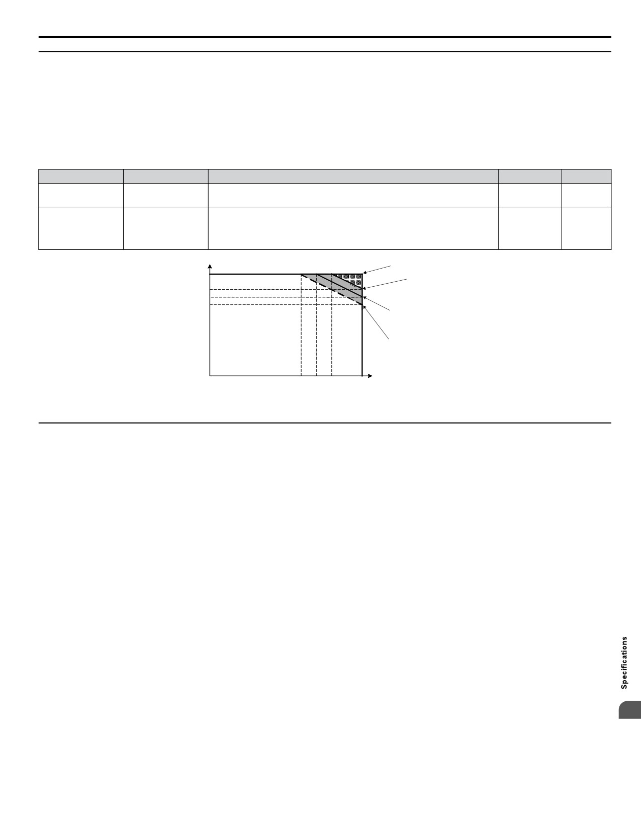
As the ambient temperature for the drive is increased above the drive specification the drive should be derated. Additionally
parameter L8-35 Installation Method Selection on page 315 should be set according to enclosure type and mounting method
as illustrated in Figure A.1.
n Output Current Derating Due to Ambient Temperature
Set L8-12 and L8-35 according to the installation conditions when the ambient temperature is above the drive specification
or when drives are mounted side-by-side in a cabinet. The output current is derated as shown in Figure A.1.
No.
Name
Description
Range
Def.
Ambient
Adjust the drive overload (oL2) protection level when the drive is installed
L8-12
-10 to 50
40 °C
Temperature Setting
in an environment that exceeds its ambient temperature rating.
0: IP20/IP00 Drive
Installation Method
1: Side-by-Side Mounting
Dep. on
L8-35
0 to 3
Selection
2: NEMA 1, UL Type 1 Drive
o2-04
3: Finless Drive or External Heatsink Installation
Parameter L8-35 = 0 (IP20/IP00 Drive)
100%
Parameter L8-35 = 2
(NEMA Type 1 Drive)
85%
80%
Drive
70%
Parameter L8-35 = 3
Rating
(Finless Drive or External
50%
Heatsink Installation)
Parameter L8-35 = 1
(Side-by-side Mounting)
0%
Ambient temp oC
o
o
o
o
-10o
30
35
40
50
Parameter L8-12
Figure A.1 Ambient Temperature and Installation Method Derating
u Altitude Derating
The drive standard ratings are valid for an installation altitude up to 1000 m. If the altitude exceeds 1000 m, both the drive
input voltage and the rated output current must be derated for 1% per 100 m. The maximum altitude is 3000 m.
A
315
A.4 Drive Derating Data
This Page Intentionally Blank
316
Appendix: B
Parameter List
This appendix contains a full listing of all parameters and settings available in the drive.
B.1
PARAMETER GROUPS
318
B.2
A: INITIALIZATION PARAMETERS
319
B.3
B: APPLICATION
320
B.4
C: TUNING
325
B.5
D: REFERENCES
327
B.6
E: MOTOR PARAMETERS
330
B.7
F: OPTIONS
333
B.8
H PARAMETERS: MULTI-FUNCTION TERMINALS
335
B.9
L: PROTECTION FUNCTION
345
B.10
N: ADVANCED PERFORMANCE SET-UP
352
B.11
O: OPERATOR RELATED PARAMETERS
353
B.12
P: PUMP PARAMETERS
356
B.13
Q: PID CONTROLLER PARAMETERS
366
B.14
S: SPECIAL APPLICATION
367
B.15
T: MOTOR TUNING
368
B.16
U: MONITORS
369
B.17
DEFAULTS BY DRIVE MODEL
377
317
B.1 Parameter Groups
B.1
Parameter Groups
Parameter
Parameter
Name
Page
Name
Page
Group
Group
A1
Initialization
319
L3
Stall Prevention
346
A2
User Parameters
319
L4
Reference Detection
348
b1
Operation Mode Selection
320
L5
Fault Restart
348
b2
DC Injection Braking
321
L6
Overtorque Detection
349
b3
Speed Search
321
L8
Hardware Protection
350
b4
Delay Timer
322
n1
Hunting Prevention
352
b5
PID Control
322
n3
High-Slip Braking
352
b6
Dwell Function
324
o1
Monitor Display Selection
353
C1
Acceleration/Deceleration Time
325
o2
Operator Keypad Functions
354
C2
S-Curve Accel/Decel
325
o3
Copy Function
354
C3
Motor Slip Compensation
326
o4
Maintenance Functions
355
C4
Motor Torque Compensation
326
P1
Pump Basic
356
C6
Carrier Frequency
326
P2
Pump Protection
358
d1
Frequency Reference
327
P4
Pump Advanced
359
d2
Reference Limits
328
P5
Pump HAND Mode
361
d3
Jump Frequencies
328
P7
Anti-Jam
362
d4
Frequency Reference Hold
329
P9
Network Options
362
E1
V/f Pattern
330
Q1
Preset Setpoint
366
E2
Motor Setup
331
Q3
Output Current Limit
366
F6
Network Communications
333
S6
Protection
367
EtherNet/IP and Modbus TCP/IP
T1
Auto-Tuning
368
F7
333
Communications
U1
Status Monitor
369
H1
Digital Inputs
335
U2
Fault Trace
372
H2
Digital Outputs
339
U3
Fault History
372
H3
Analog Inputs
341
U4
Maintenance Monitor
374
H4
Analog Outputs
343
U5
PID Monitor
376
H5
Serial Communications Setup
343
U6
Control Monitor
376
H6
Pulse Train I/O Setup
344
U9
Operation Status Monitors
376
L1
Motor Overload
345
L2
Power Loss Ride-Thru
346
318
B.2 A: Initialization Parameters
B.2
A: Initialization Parameters
Table B.1 Symbols and Icons Used in Parameter Descriptions
Symbol
Description
Parameter can be changed during run.
The A parameter group creates the operating environment for the drive. This includes the parameter Access Level, Motor
Control Method, Password, User Parameters and more.
u A1: Initialization
No.
(Addr.
Name
LCD Display
Description
Values
Page
Hex)
Select Language
0: English
0: English
1: Japanese
A1-00
1:
(Japanese)
2: German
(0100)
2: Deutsch
3: French
Default: 0
Language Selection
3: Français
4: Italian
110
Range: 0 to 7
4: Italiano
5: Spanish
<1>
5: Español
6: Portuguese
6: Português
7: Chinese
7:
0: View and set A1-01 and A1-04. Uo-oo parameters can also
A1-01
Access Level
be viewed.
(0101)
0: Operation Only
1: User Parameters (access to parameters selected by the user,
Default: 2
Access Level Selection
1: User Parameters
110
A2-01 to A2-32)
Range: 0 to 3
2: Advanced Level
<2>
2: Advanced Access (access to view and set all parameters)
3: Lock parameters
3: Lock parameters
Init Parameters
0: No initialization
0: No Initialize
1110: User Initialize (parameter values must be stored using
1110: User Initialize
parameter o2-03)
2220: 2-Wire Initial
2220: 2-Wire initialization
Default: 0
3330: 3-Wire Initial
3330: 3-Wire initialization
A1-03
Range: 0 to 5550;
Initialize Parameters
5550: Term->Cntrl Int
5550: Terminal->Control Initialize
111
(0103)
6008, 6009, 7770,
6008: Pressure Control
6008: Pressure Control
7771
6009: Pump down level
6009: Pump down level
7770: General purpose
7770: General purpose
7771: Sub Mtr GP
7771: Submersible motor GP operation
Operation
A1-04
When the value set into A1-04 does not match the value set into
Password
Enter Password
Default: 0000
(0104)
A1-05, parameters A1-01 through A1-03 and A2-01 through A2-33
Min.: 0000
112
A1-05
cannot be changed.
Password Setting
Select Password
Max.: 9999
(0105)
0: Pressure control
Application Sel
1: General purpose
0: Pressure Control
2: Submersible motor GP operation
1: General Purpose
A1-06
8: Pressure control
Default: 0
Application Preset
2: Sub Mtr GP
86
(0127)
9: Pump down level
Range: 0 to 2: 8, 9
Operation
8: Pressure Control
Note:
This parameter is not settable. It is used as a
9: Pump Down Level
monitor only.
<1> Parameter setting value is not reset to the default value when the drive is initialized.
<2> Default setting value is dependent on the Initialization parameter A1-03.
u A2: User Parameters
No.
(Addr.
Name
LCD Display
Description
Values
Page
Hex)
A2-01 to
Recently edited parameters are listed here. The user can also select
Default: <1>
A2-32
parameters to appear here for quicker access.
User Parameters 1 to 32
User Param 1 - 32
Range: b1-01 to
113
(0106 to
S6-02
0125)
0: A2-01 to A2-32 are reserved for the user to create a list of User
User Parms Sel
Parameters.
A2-33
User Parameter
Default: 0
-
0: Disabled
1: Save history of recently viewed parameters. Recently edited
(0126)
Automatic Selection
Range: 0, 1
113
B
1: Enabled
parameters will be saved to A2-17 through A2-32 for quicker
access.
<1> Default setting value is dependent on the Initialization parameter A1-03.
319
B.3 b: Application
B.3
b: Application
Application parameters configure the Run Command Source, Timer functions, PID control, and a variety of other application-
related settings.
u b1: Operation Mode Selection
No.
(Addr.
Name
LCD Display
Description
Values
Page
Hex)
Ref Source 1
0: Operator (will also switch PID setpoint to Q1-01)
0: Operator
1: Analog input terminals
b1-01
Frequency Reference
1: Analog Input
2: MEMOBUS/Modbus communications
Default: 0
115
(0180)
Selection 1
2: Serial Com
3: Option PCB
Range: 0 to 4
3: Option PCB
4: Pulse input (terminal RP)
4: Pulse Input
Run Source 1
0: HOA keypad
0: Operator
1: Digital input terminals
b1-02
Run Command
Default: 0
1: Digital Inputs
2: MEMOBUS/Modbus communications
118
(0181)
Selection 1
Range: 0 to 3
2: Communication
3: Option PCB
3: Option PCB
Stopping Method
0: Ramp to stop
0: Ramp to Stop
1: Coast to stop
b1-03
Stopping Method
Default: 1
1: Coast to Stop
2: DC Injection Braking to stop
118
(0182)
Selection
Range: 0 to 3
2: DCInj to Stop
3: Coast with timer
3: Coast w/Timer
Reverse Oper
0: Reverse enabled
b1-04
Reverse Operation
Default: 1
0: Reverse Enabled
1: Reverse disabled
120
(0183)
Selection
Range: 0, 1
1: Reverse Disabled
Determines whether the run command is retained when the
Run Command
RunCmd@SrcChange
b1-07
Sequence Selection is changed
Default: 0
Retention when Source
0: Require Cycle
121
(0186)
0: Require Cycle
Range: 0, 1
is Changed
1: Retain Run Cmd
1: Retain Run Command
RUN dur PRG Mode
0: Run command is not accepted while in Programming Mode.
0: Run
1: Run command is accepted while in Programming Mode.
Run Command
b1-08
Disabled@PRG
2: Prohibit entering Programming Mode during run.
Default: 0
Selection in
121
(0187)
1: ModeRun
Range: 0 to 2
Programming Mode
Enabled@PRG
2: Prg only @ Stop
Sets the amount of time that the drive will disallow the
reapplication of the Run command after the Run command is
Default: 0.0 s
b1-11
Run Delay at Stop
lost. b1-11 is active for all b1-03 settings.
Run Delay @ Stop
Min.: 0.0
-
(01DF)
(Back Spin Timer)
If set to zero and b1-03 = 3 (Coast to Stop w/ Timer), a
Max.: 6000.0
combination of C1-02 and output frequency determine the
length of time. Otherwise, no run delay will be applied.
Determines whether the Run Delay Timer is saved to the
EEPROM during power loss.
0: Disabled
1: Only at Stop
b1-12
Run Delay Memory
2: Running & Stop
Default: 2
Run Dly Mem Sel
-
(01E0)
Selection
Range: 0 to 2
Note:
A JVOP-183 HOA Keypad must be plugged into
the drive for settings 1 and 2 to function. If the
keypad is removed, b1-12 will function as setting
0 (Disabled).
Rotation Sel
0: Standard
b1-14
Default: 0
Phase Order Selection
0: Standard
1: Switch phase order (reverses the direction of the motor)
122
(01C3)
Range: 0, 1
1: SwitchPhaseOrder
Enabled when a multi-function digital input set for “External
Ref Source 2
Reference” (H1-oo = 2) closes.
0: Operator
0: Operator
b1-15
Frequency Reference
1: Analog Input
Default: 0
1: Analog Input
123
(01C4)
Selection 2
2: Serial Com
Range: 0 to 4
2: Serial Communications
3: Option PCB
3: Option PCB
4: Pulse Input
4: Pulse Input
320