Yaskawa iQpump Micro AC Drive Compact Intelligent Pump Controller. User Manual (2014) - page 6
5.8 L: Protection Functions
No.
Name
Setting Range
Default
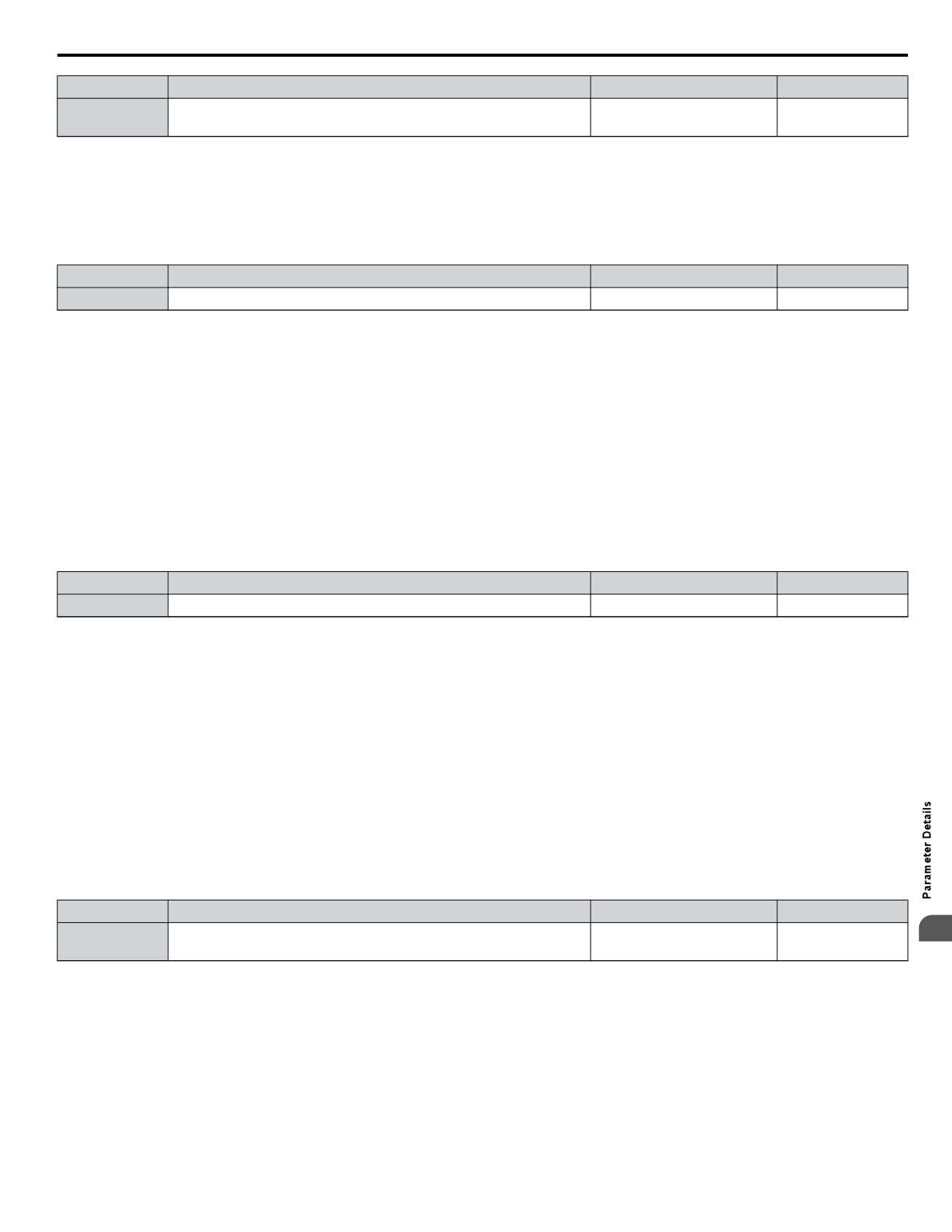
Target DC Bus Voltage for Overvoltage Suppression, and
L3-17
150 to 400 <1>
375 V <1> <2>
Intelligent Stall Prevention During Deceleration
<1> Values are for 200 V class drives and must be doubled for 400 V class drives.
<2> This value is initialized when E1-01 is changed.
n L3-20: DC Bus Voltage Adjustment Gain
Determines the proportional gain used by overvoltage suppression (L3-11 = 1), Kinetic Energy Backup 2, and Intelligent Stall
Prevention during deceleration (L3-04 = 2) in order to control the DC bus voltage.
No.
Name
Setting Range
Default
L3-20
DC Bus Voltage Adjustment Gain
0.00 to 5.00
1.00
Adjustment for KEB 2 and Intelligent Stall Prevention During Deceleration
• Increase this setting slowly in steps of 0.1 if overvoltage (ov) or undervoltage (Uv1) occurs at the beginning of deceleration
while KEB Ride-Thru 2 is enabled or Intelligent Stall Prevention during deceleration is activated.
• If this setting is too high, then a fair amount of speed or torque ripple can result.
Adjustment for Overvoltage Suppression
• Increase this setting slowly in steps of 0.1 if overvoltage suppression is enabled (L3-11 = 1) and a sudden increase in a
regenerative load results in an overvoltage (ov) fault.
• If this setting is too high, excessive speed or torque ripple can result.
n L3-21: Accel/Decel Rate Calculation Gain
Determines the proportional gain used by overvoltage suppression (L3-11 = 1), Kinetic Energy Backup 2, and Intelligent Stall
Prevention during deceleration (L3-04 = 2) in order to calculate acceleration and deceleration rates.
No.
Name
Setting Range
Default
L3-21
Accel/Decel Rate Calculation Gain
0.10 to 10.00
1.00
Adjustment for KEB 2 and Intelligent Stall Prevention During Deceleration
• Reduce the setting in steps of 0.05 if there is a fairly large speed or current ripple during KEB Ride-Thru 2 or when using
Intelligent Stall Prevention during deceleration.
• Small reductions in the acceleration gain can also help solve problems with overvoltage and overcurrent.
• Decreasing this setting too much can result in a slow DC bus voltage control response and may also lengthen deceleration
times beyond optimal levels.
Adjustment for Overvoltage Suppression
• Increase this setting in steps of 0.1 if overvoltage occurs as a result of a regenerative load when overvoltage suppression is
enabled (L3-11 = 1).
• If there is a fairly large speed ripple when overvoltage suppression is enabled, then decrease L3-21 in steps of 0.05.
n L3-23: Automatic Stall Prevention Level Reduction
This function reduces the Stall Prevention during run level in the constant power range.
No.
Name
Setting Range
Default
Automatic Reduction Function Selection for Stall Prevention during
5
L3-23
0 or 1
0
Run
Setting 0: Disabled
The level set in L3-06 is used throughout the entire speed range.
Setting 1: Enabled
The Stall Prevention level during run is reduced in the constant power range. The lower limit will be 40% of L3-06.
n Overvoltage Suppression Function
This function suppresses overvoltage faults by slightly increasing the output frequency when the DC bus voltage rises. It can
be used to drive loads with cyclic regenerative operation, such as punch presses or other applications that involve repetitive
crank movements.
201
5.8 L: Protection Functions
The output frequency is adjusted during ov suppression so that the DC bus voltage does not exceed the level set in parameter
L3-17. In addition to the parameters explained below, ov suppression also uses these settings for frequency adjustment:
• DC bus voltage gain L3-20
• Deceleration rate calculations gain L3-21
• Inertia calculations for motor acceleration time L3-24
• Load inertia ratio L3-25
Note:
1. The motor speed will exceed the frequency reference when overvoltage suppression is triggered. Consequently, overvoltage suppression
is not appropriate in applications that require a perfect match between the frequency reference and the actual motor speed.
2. Disable overvoltage suppression when using a braking resistor.
3. Overvoltage may still occur if there is a sudden increase to a regenerative load.
4. This function is enabled only when operating just below the maximum frequency. Overvoltage suppression does not increase the output
frequency beyond the maximum frequency. If this is required by the application increase the maximum frequency and change the base
frequency setting.
n L3-24: Motor Acceleration Time for Inertia Calculations
Sets the time it takes to accelerate the motor from stop to the maximum speed at motor rated torque. This parameter should
be set when using KEB Ride-Thru 2, Intelligent Stall Prevention during deceleration (L2-04 = 2), or the overvoltage suppression
function (L3-11 = 1).
No.
Name
Setting Range
Default
<1>
L3-24
Motor Acceleration Time for Inertia Calculations
0.001 to 10.000
<1> Parameter value changes automatically if E2-11 is manually changed or changed by Auto-Tuning. Default setting is dependent on parameter o2-04,
Drive Model Selection.
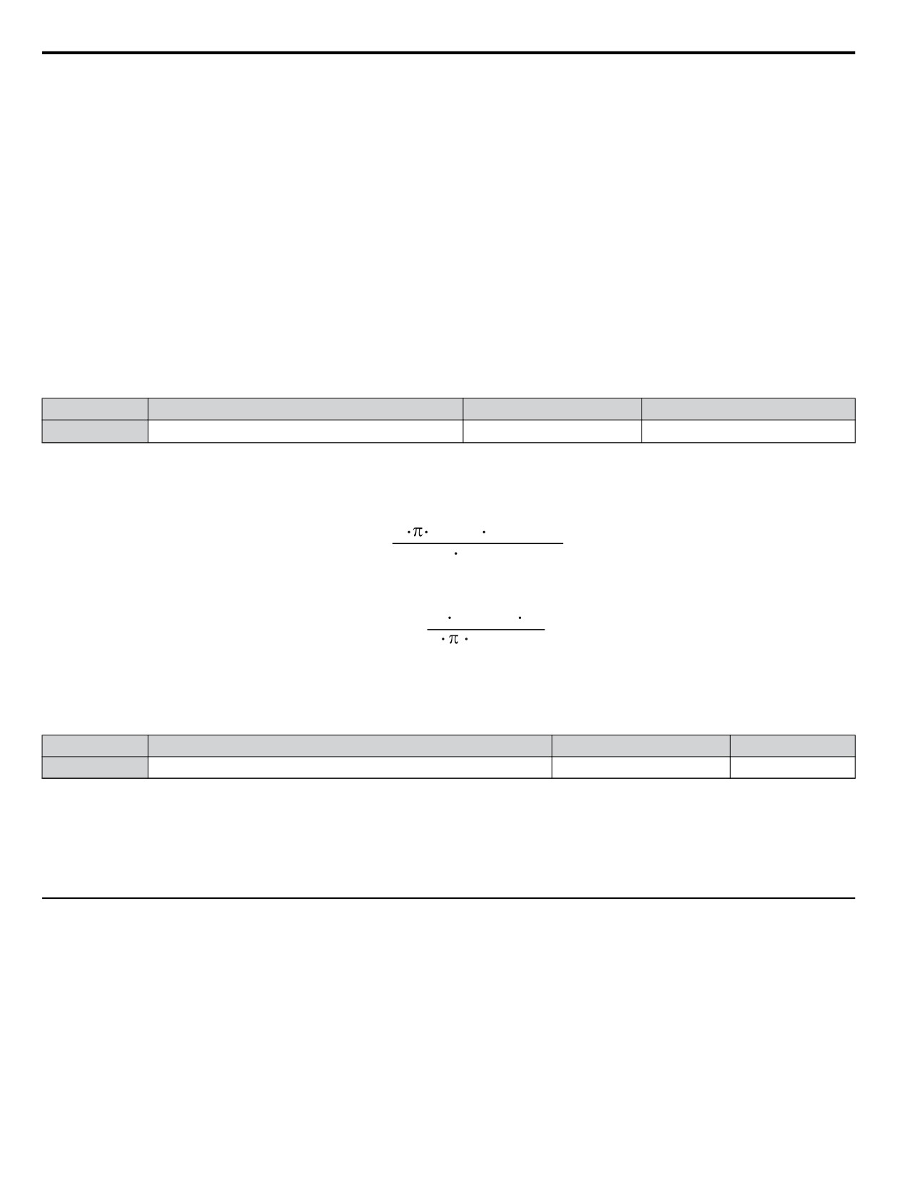
Calculations are made as follows:
2
J [kgm2] n
rated
[r/min]
L3-24 =
60 T
rated
[Nm]
The rated torque can be calculated as follows:
60 P
Motor
[kW]
103
T
[Nm] =
rated
2
n
[r/min]
rated
n L3-25: Load Inertia Ratio
Determines the ratio between the rotor inertia and the load. Set this parameter when using KEB Ride-Thru 2, Intelligent Stall
Prevention during deceleration (L3-04 = 2), or the overvoltage suppression function (L3-11 = 1).
No.
Name
Setting Range
Default
L3-25
Load Inertia Ratio
1.0 to 1000.0
1.0
When set incorrectly, a fairly large current ripple can result during KEB Ride-Thru 2 and overvoltage suppression (L3-11 =
1) or other faults such as ov, Uv1, and oC may occur.
Parameter L3-25 can be calculated by:
Machine Inertia
L3-25 =
Motor Inertia
u L4: Speed Agree/Frequency Reference Loss Detection
These parameters set up the speed agree and speed detection functions which can be assigned to the multi-function output
terminals.
n L4-01/02: Speed Agreement Detection Level and Detection Width
Parameter L4-01 sets the detection level for the digital output functions “Speed Agree 1”, “User Set Speed Agree 1”,
“Frequency Detection 1”, and “Frequency Detection 2”.
Parameter L4-02 sets the hysteresis level for these functions.
202
5.8 L: Protection Functions
No.
Name
Setting Range
Default
L4-01
Speed Agreement Detection Level
0.0 to 400.0 Hz
0.0 Hz
L4-02
Speed Agreement Detection Width
0.0 to 20.0 Hz
2.0 Hz
Refer to H2-01 to H2-03: Terminal MA/MB/MC, P1/PC, and P2/PC Function Selection on page 174, Settings 2, 3, 4, and
5.
n L4-03/04: Speed Agreement Detection Level and Detection Width (+/-)
Parameter L4-03 sets the detection level for the digital output functions “Speed Agree 2”, “User Set Speed Agree 2”,
“Frequency Detection 3”, and “Frequency Detection 4”.
Parameter L4-04 sets the hysteresis level for these functions.
No.
Name
Setting Range
Default
L4-03
Speed Agreement Detection Level (+/-)
0.0 to 400.0 Hz
0.0 Hz
L4-04
Speed Agreement Detection Width (+/-)
0.0 to 20.0 Hz
2.0 Hz
Refer to H2-01 to H2-03: Terminal MA/MB/MC, P1/PC, and P2/PC Function Selection on page 174, Settings 13, 14, 15,
and 16.
n L4-05: Frequency Reference Loss Detection Selection
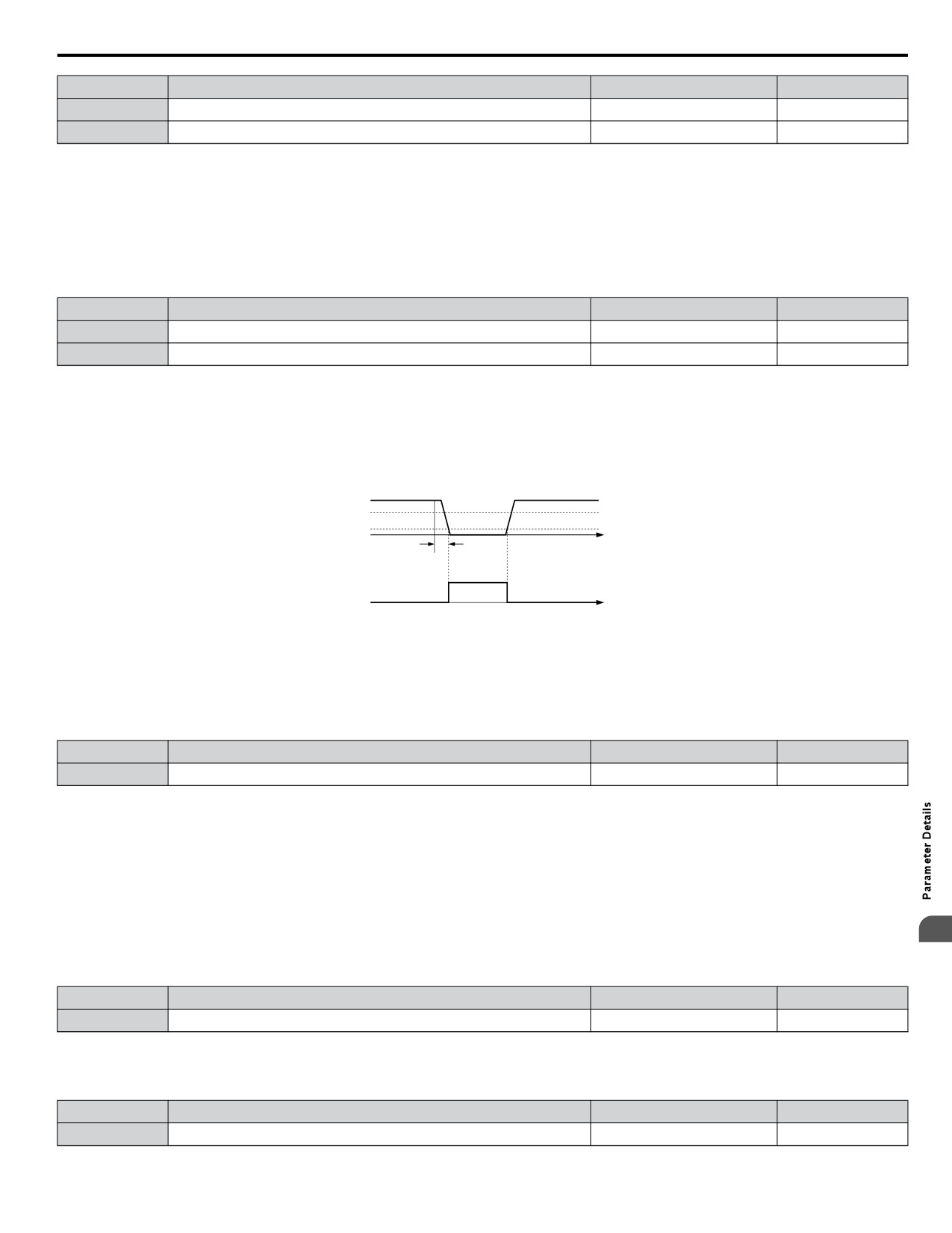
The drive can detect a loss of an analog frequency reference from input A1 or A2. Reference loss is detected when the frequency
reference value reduces for 90% within 400 ms.
100%
Analog
frequency
80%
reference
10%
400ms
Loss of
Reference
OFF
ON
output
time
Figure 5.75 Loss of Reference Function
To have a fault output trigger when frequency reference loss occurs, set H2-01, H2-02, or H2-03 to “C”. Refer to Setting C:
Frequency Reference Loss on page 177 for details on setting the output function.
Parameter L4-05 selects the operation when a frequency reference loss is detected.
No.
Name
Setting Range
Default
L4-05
Frequency Reference Loss Detection Selection
0 or 1
0
Setting 0: Stop
The drive will stop the motor.
Setting 1: Continue Operation with Reduced Frequency Reference
The drive will continue operation at the frequency reference value set in parameter L4-06. When the external frequency
reference value is restored, the operation is continued with the frequency reference.
n L4-06: Frequency Reference at Reference Loss
5
Sets the frequency reference level the drive runs with when L4-05 = 1 and a reference loss was detected. The value is set as
a percentage of the frequency reference before the loss was detected.
No.
Name
Setting Range
Default
L4-06
Frequency Reference at Reference Loss
0.0 to 100.0%
80.0%
n L4-07: Speed Agreement Detection Selection
Determines when frequency detection is active using parameters L4-01 through L4-04.
No.
Name
Setting Range
Default
L4-07
Speed Agreement Detection Selection
0, 1
0
203
5.8 L: Protection Functions
Setting 0: No Detection During Baseblock
Setting 1: Detection Always Enabled
u L5: Fault Restart
The drive can be set up to perform a self-diagnostic check and resume the operation after a fault has occurred. If the self-check
is successful and the cause of the fault has disappeared, the drive restarts by performing Speed Search.
The drive can attempt to restart itself following the faults listed below.
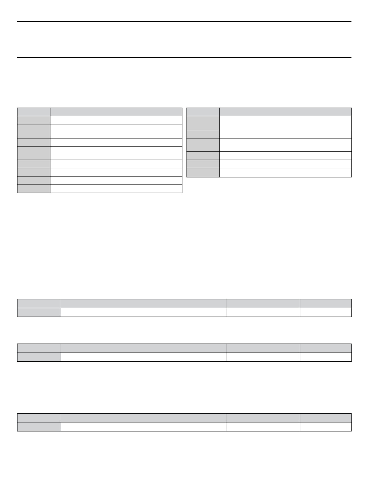
Table 5.26 Restart Faults
Setting
Function
Setting
Function
GF
(Ground Fault)
ov
(DC Bus Overvoltage)
LF
(Output Open Phase)
PF
(Input Phase Loss)
oC
(Overcurrent)
rH
(Braking Resistor Fault)
oH1
(Drive Overheat)
rr
(Braking Transistor Fault)
oL1
(Motor Overload)
STo
(Step Out Detection)
oL2
(Drive Overload)
Uv1
(DC Bus Undervoltage) <1>
oL3
(Overtorque 1)
oL4
(Overtorque 2)
<1> When L2-01 is set to 1 or 2 (continue operation during momentary power loss)
To output a signal during fault restart, set H2-01, H2-02, or H2-03 to 1E.
n L5-01: Number of Auto Restart Attempts
Sets the number of times that the drive may attempt to restart itself.
When the counter reaches the number set to L5-01, the operation stops and the fault must be manually cleared and reset.
The restart counter is incremented at each restart attempt, regardless of whether the attempt was successful. When the counter
reaches the number set to L5-01, the operation stops and the fault must be manually cleared and reset.
The number of fault restarts is reset to zero when:
• The drive operates normally for 10 minutes following a fault restart.
• A fault is cleared manually after protective functions are triggered.
• The power supply is cycled.
No.
Name
Setting Range
Default
L5-01
Number of Auto Restart Attempts
0 to 10 Times
5 Times
n L5-02: Auto Restart Fault Output Operation Selection
Selects if the fault output (H2-01/02/03 = E) is set when the drive attempts to restart.
No.
Name
Setting Range
Default
L5-02
Auto Restart Fault Output Operation Selection
0 or 1
0
Setting 0: No Fault Output
Setting 1: Fault Output is Set
n L5-04: Fault Reset Interval Time
Determines the amount of time to wait between restart attempts when parameter L5-05 is set to 1.
No.
Name
Setting Range
Default
L5-04
Fault Reset Interval Time
10.0 to 3600.0 s
20.0 s
n Auto Restart for Faults
The Auto Restart function several faults can be disabled and enabled in parameters L5-40 to L5-53.
204
5.8 L: Protection Functions
n L5-40: Low Feedback Fault Retry Selection
No.
Name
Setting Range
Default
L5-40
Low Feedback Fault Retry Selection
0, 1
0
Setting 0: No retry
Setting 1: Retry
n L5-41: High Feedback Fault Retry Selection
No.
Name
Setting Range
Default
L5-41
High Feedback Fault Retry Selection
0, 1
0
Setting 0: No retry
Setting 1: Retry
n L5-42: Feedback Loss Fault Retry Selection
No.
Name
Setting Range
Default
L5-42
Feedback Loss Fault Retry Selection
0, 1
0
Setting 0: No retry
Setting 1: Retry
n L5-50: Setpoint Not Met Retry Selection
No.
Name
Setting Range
Default
L5-50
Setpoint Not Met Retry Selection
0, 1
0
Setting 0: No retry
Setting 1: Retry
n L5-51: Loss of Prime Fault Retry Selection
No.
Name
Setting Range
Default
L5-51
Loss of Prime Fault Retry Selection
0, 1
0
Setting 0: No retry
Setting 1: Retry
n L5-52: Pump Over Cycle Fault Retry Selection
No.
Name
Setting Range
Default
L5-52
Pump Over Cycle Fault Retry Selection
0, 1
0
Setting 0: No retry
Setting 1: Retry
n L5-53: Volute-Thermostat Retry Selection
No.
Name
Setting Range
Default
L5-53
Volute-Thermostat Retry Selection
0, 1
0
n Volute Thermostat Digital Inputs
5
There are two multi-function digital input settings, one normally open (closed causes the fault) and one normally closed (open
causes the fault). Only one of these inputs may be programmed into the H1-oo parameters at a time.
Setting 0: No retry
Setting 1: Retry
When automatic retries are enabled (L5-01 > 0) and the drive faults on FLTS - Volute-TStat Flt , the drive will wait for the
Volute-Thermostat digital input to deactivate plus the L5-04 time before the drive will restart.
u L6: Torque Detection
The drive provides two independent torque detection functions that trigger an alarm or fault signal when the load is too heavy
(oL), or suddenly drops (UL). They are set up using the L6-oo parameters. To indicate the underload or overload condition
to an external device, digital outputs should be programmed as shown below.
205
5.8 L: Protection Functions
H2-01 /02/03 Setting
Description
B
Torque detection 1, N.O. (output close when over-/underload is detected)
17
Torque detection 1, N.C. (output opens when over-/underload is detected)
18
Torque detection 2, N.O. (output close when over-/underload is detected)
19
Torque detection 2, N.C. (output opens when over-/underload is detected)
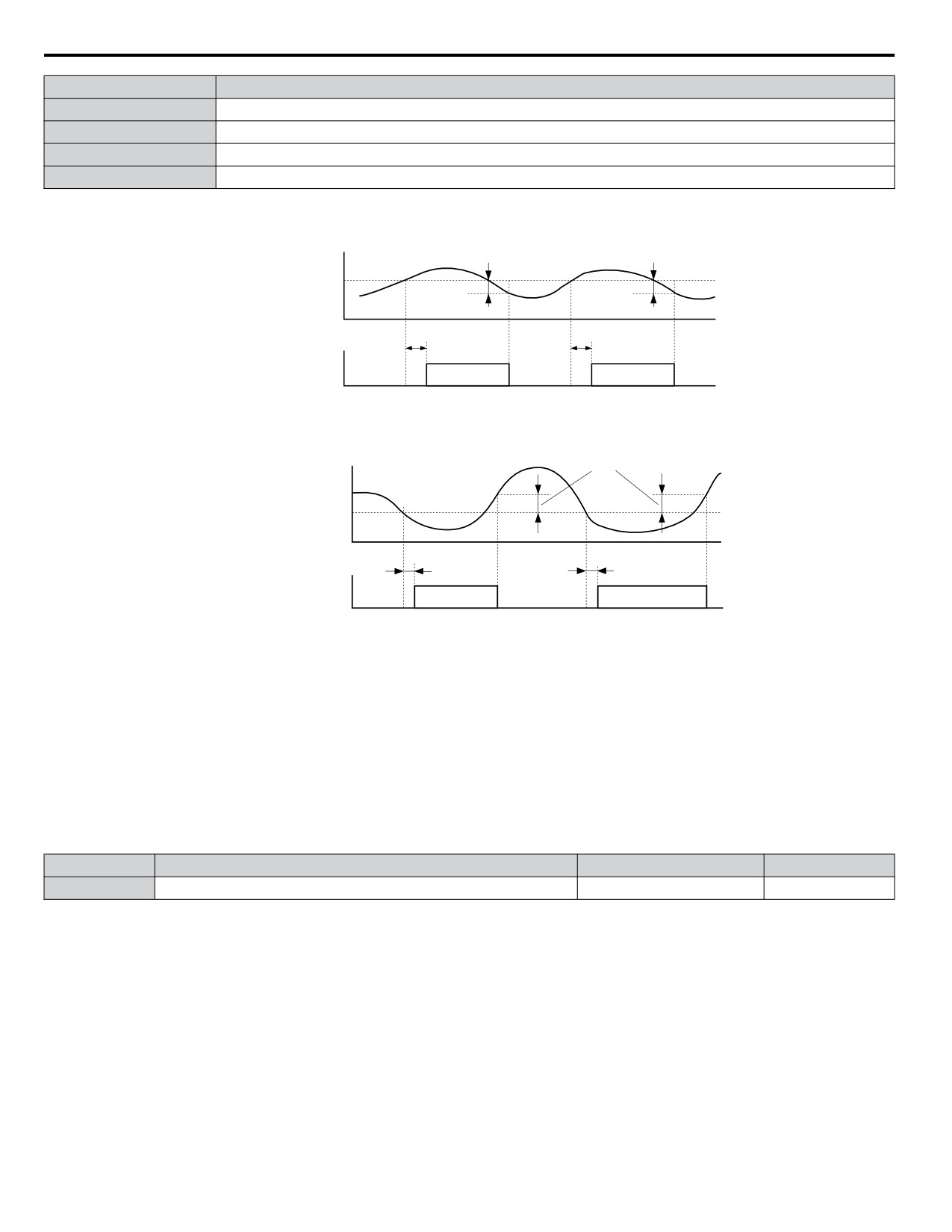
Figure 5.76 and Figure 5.77 show the function of overtorque and undertorque detection.
Motor current / torque
10 % hysteresis
10 % hysteresis
L6-02/05
L6-03/06
L6-03/06
Torque detection 1 (NO)
or
ON
ON
Torque detection 2 (NO)
Figure 5.76 Overtorque Detection Operation
Motor current / torque
10 % hysteresis
L6-02/05
L6-03/06
L6-03/06
Torque detection 1 (NO)
or
ON
ON
Torque detection 2 (NO)
Figure 5.77 Undertorque Detection Operation
Note:
The torque detection function uses a hysteresis of 10% of the drive rated output current/motor rated torque.
Note:
When overtorque occurs in the application, the drive may stop due to overcurrent (oC) or overload (oL1). To prevent this, an overload
situation should be indicated to the controller before oC or oL1 occur in the drive. Use the torque detection for this purpose. Use undertorque
detection to discover application problems like a torn belt, a pump shutting off, or other similar trouble.
n L6-01/L6-04: Torque Detection Selection 1/2
The torque detection function is triggered when the current/torque exceeds the levels set in parameter L6-02/L6-05 for longer
than the time set in L6-03L6-/06. The parameters L6-01/L6-04 select the detection condition and the operation at detection.
No.
Name
Setting Range
Default
L6-01/ L6-04
Torque Detection Selection 1/2
0 to 8
0
Setting 0: Disabled
Setting 1: oL3/oL4 at Speed Agree - Alarm
Overtorque detection is active only when the output speed is equal to the frequency reference, i.e., no detection during
acceleration and deceleration. The operation continues after detection and an oL3/oL4 alarm is triggered.
Setting 2: oL3/oL4 at Run - Alarm
Overtorque detection works whenever a Run command is active. The operation continues after detection and an oL3/oL4
alarm is triggered.
Setting 3: oL3/oL4 at Speed Agree - Fault
Overtorque detection is active only when the output speed is equal to the frequency reference, i.e., no detection during
acceleration and deceleration. The operation is stopped and an oL3/oL4 fault is triggered.
206
5.8 L: Protection Functions
Setting 4: oL3/oL4 at Run - Fault
Overtorque detection works whenever a Run command is active. The operation is stopped and an oL3/oL4 fault is triggered.
Setting 5: UL3/UL4 at Speed Agree - Alarm
Undertorque detection is active only when the output speed is equal to the frequency reference, i.e., no detection during
acceleration and deceleration. The operation continues after detection and a UL3/UL4 alarm is triggered.
Setting 6: oL5/UL5 at Run - Alarm
Undertorque detection works whenever a Run command is active. The operation continues after detection and an oL5/UL5
alarm is triggered.
Setting 7: UL5 at Speed Agree - Fault
Undertorque detection is active only when the output speed is equal to the frequency reference, i.e., no detection during
acceleration and deceleration. The operation is stopped and a UL5 fault is triggered.
Setting 8: oL3/oL4 at Run - Fault
Undertorque detection works whenever a Run command is active. The operation is stopped and an oL3/oL4 fault is triggered.
Setting 9: UL6 Alarm at Speed Agree
Setting 10: UL6 Alarm during Run
Setting 11: UL6 Fault at Speed Agree
Setting 12: UL6 Fault during Run
n L6-02/L6-05: Torque Detection Level 1/2
These parameters the detection levels for the torque detection functions 1 and 2.
No.
Name
Setting Range
Default
L6-02
Torque Detection Level 1
0 to 300%
150%
L6-05
Torque Detection Level 2
0 to 300%
150%
Note:
1. The torque detection level 1 (L6-02) can also be supplied by an analog input set to H3-02/10 = 7. In this case the analog value has priority
and the setting L6-02 is disregarded. Torque detection level 2 (L6-05) cannot be set by an analog input.
2. The detection levels for overtorque and undertorque are set as a percentage of the drive rated current when using V/f Control or Open
Loop Vector Control. When using Closed Loop Vector Control, the drive sets torque detection as a percentage of the motor rated current.
n L6-03/L6-06: Torque Detection Time 1/2
These parameters set the time that the levels set in L6-02/05 have to be exceeded before an alarm/fault is triggered.
No.
Name
Setting Range
Default
L6-03
Torque Detection Time 1
0.0 to 10.0 s
0.1 s
L6-06
Torque Detection Time 2
0.0 to 10.0 s
0.1 s
n L6-13: Motor Underload Protection Selection
Sets the motor underload protection (UL6) based on motor load.
No.
Name
Setting Range
Default
L6-13
Motor Underload Protection Selection
0, 1
0
Setting 0: Base frequency enable
5
Setting 1: Max frequency enable
n L6-14: Motor Underload Protection Level at Minimum Frequency
Sets the motor underload protection (UL6) based on motor load.
No.
Name
Setting Range
Default
L6-14
Motor Underload Protection Level at Minimum Frequency
0 to 300%
15%
u L8: Hardware Protection
207
5.8 L: Protection Functions
n L8-01: Internal Dynamic Braking Resistor Protection Selection (ERF type)
This parameter selects the dynamic braking resistor protection when using an optional heatsink mounted braking resistor (ERF
type, 3% ED).
No.
Name
Setting Range
Default
L8-01
Internal Braking Resistor Protection
0 or 1
0
Setting 0: Disabled
Disables the braking resistor protection. Use this setting for any braking option other than the Yaskawa ERF Type resistor.
Setting 1: Enabled
Enables the protection for ERF type resistors.
n L8-02: Overheat Alarm Level
Sets the overheat alarm (oH) detection level.
The drive will output an alarm when the heatsink temperature exceeds the alarm level set in parameter L8-02. If the temperature
reaches the overheat fault level, the drive will trigger an oH1 fault and stop operation.
When an output terminal is set for the oH pre-alarm (H2-01/02/03 = 20), the switch will close when the heatsink temperature
rises above L8-02.
No.
Name
Setting Range
Default
Determined by
L8-02
Overheat Alarm Level
50 to 130 °C
o2-04
n L8-03: Overheat Pre-Alarm Operation Selection
Sets the operation when an overheat pre-alarm is detected.
No.
Name
Setting Range
Default
L8-03
Overheat Pre-Alarm Operation
0 to 4
3
Setting 0: Ramp to Stop
If an overheat alarm occurs, the drive decelerates to stop using the selected deceleration time. If a digital output is programmed
for “fault” (H2-01/02/03 = E), this output will be triggered.
Setting 1: Coast to Stop
If an overheat alarm occurs, the drive switches off the output and the motor coasts to stop. If a digital output is programmed
for “fault” (H2-01/02/03 = E), this output will be triggered.
Setting 2: Fast-stop
If an overheat alarm occurs, the drive decelerates to stop using the Fast-stop time (C1-09). If a digital output is programmed
for “fault” (H2-01/02/03 = E), this output will be triggered.
Setting 3: Alarm Only
If an overheat alarm occurs, an alarm is output and the drive continues operation.
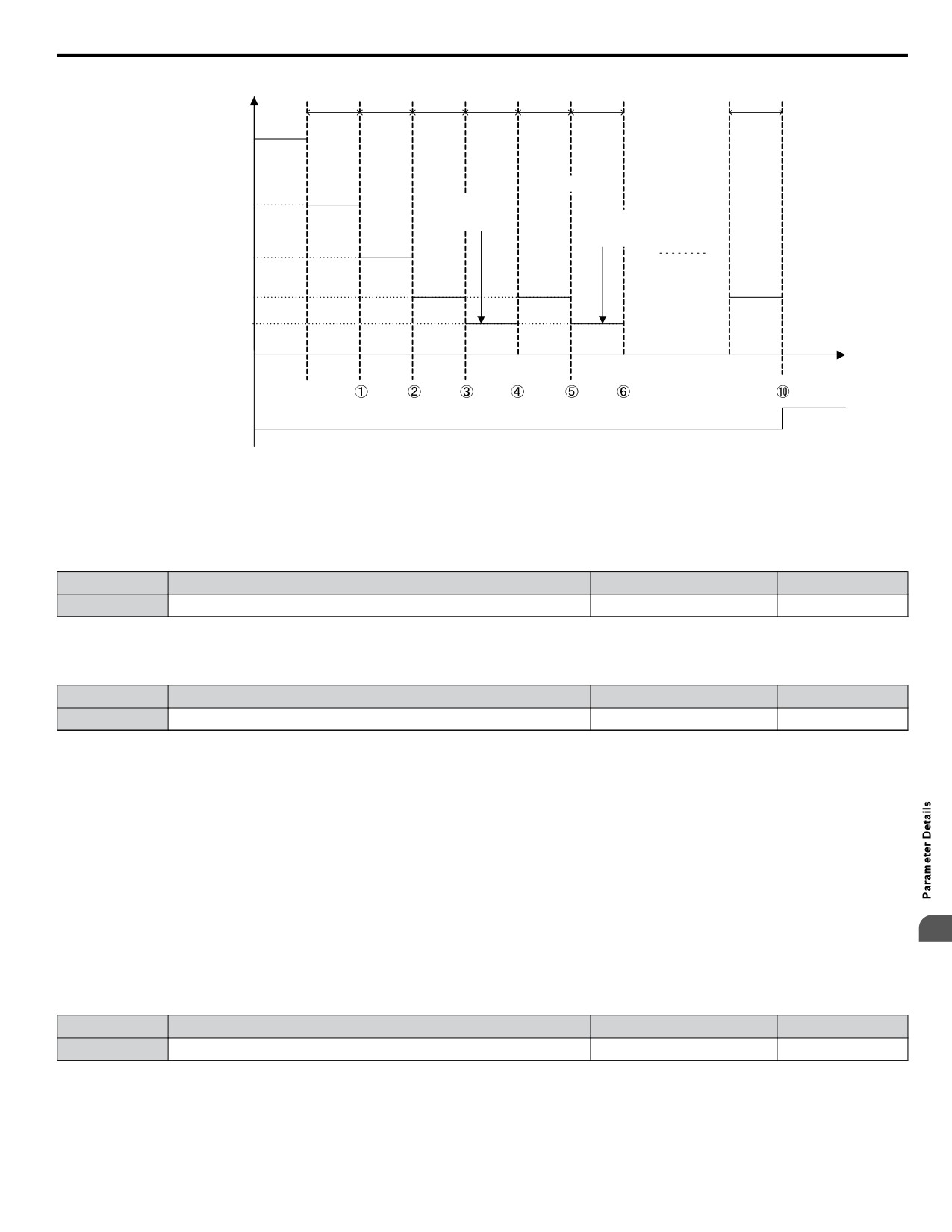
Setting 4: Operation with Reduced Speed
If an overheat alarm occurs, the operation is continued but the speed is reduced to the level set in parameter L8-19. If after 10
s the oH alarm is still present, the speed is reduced once more. The amount of reduction depends on how often the alarm
repeats. If the oH alarm disappears while the drive is operating at a reduced speed, then the drive will switch back to the
previous speed it was reduced to before. Figure 5.78 explains the operation with reduced speed during an oH alarm. A digital
output programmed for 4D is switched when the oH alarm is still active after ten reduction cycles.
208
5.8 L: Protection Functions
Output frequency
10 s
10 s
10 s
10 s
10 s
10 s
10 s
fref
oH
Alarm
fref × (L8-19)
Reset oH
Alarm
Reset oH
oH
Alarm
Alarm
fref × (L8-19)2
oH
etc.
oH
Alarm
Alarm
fref
× (L8-19)3
fref
× (L8-19)4
oH Alarm number
Time
Digital output (4D)
Figure 5.78 Output Frequency Reduction During Overheat Alarm
n L8-19: Frequency Reduction Rate During Overheat Pre-Alarm
Specifies how much the output frequency is reduced when L8-03 is set to 4 and an oH alarm is present. Set as a factor of the
maximum output frequency.
No.
Name
Setting Range
Default
L8-19
Frequency Reduction Rate During oH Pre-Alarm
0.1 to 0.9
0.8
n L8-05: Input Phase Loss Protection Selection
Enables or disables the input phase loss detection.
No.
Name
Setting Range
Default
L8-05
Input Phase Loss Detection Selection
0 or 1
1
Setting 0: Disabled
Setting 1: Enabled
Enables the input phase loss detection. As detection is performed by measuring the DC bus ripple, a phase loss fault (PF) can
also be triggered by power supply voltage imbalance or main circuit capacitor deterioration. Detection is disabled when:
• The drive is decelerating.
• No Run command is active.
• Output current is less than or equal to 30% of the drive rated current.
n L8-07: Output Phase Loss Protection Selection
5
Enables or disables the output phase loss detection, which is triggered when the output current falls below 5% of the drive
rated current.
Note:
Output phase loss detection can mistakenly be triggered if the motor rated current is very small compared to the drive rating. Disable this
parameter in such cases.
No.
Name
Setting Range
Default
L8-07
Output Phase Loss Protection Selection
0 to 2
1
Setting 0: Disabled
Setting 1: Fault when One Phase is Lost
An output phase loss fault (LF) is triggered when one output phase is lost. The output shuts off and the motor coasts to stop.
209
5.8 L: Protection Functions
Setting 2: Fault when Two Phases are Lost
An output phase loss fault (LF) is triggered when two output phases are lost. The output shuts off and the motor coasts to stop.
n L8-09: Output Ground Fault Detection Selection
Enables or disables the output ground fault detection.
No.
Name
Setting Range
Default
L8-09
Output Ground Fault Detection
0 or 1
0
Setting 0: Disabled
Ground faults are not detected.
Setting 1: Enabled
A ground fault (GF) is triggered when high leakage current or a ground short circuit occurs in one or two output phases.
n L8-10: Heatsink Cooling Fan Operation Selection
Selects the heatsink cooling fan operation.
No.
Name
Setting Range
Default
L8-10
Fan Operation Selection
0 or 1
0
Setting 0: Run with Timer
The fan is switched on when a Run command is active. It is switched off with the delay set in parameter L8-11 after the Run
command has been released. Using this setting extends the fan lifetime.
Setting 1: Run always
The fan runs whenever power is supplied to the drive.
n L8-11: Heatsink Cooling Fan Off Delay Time
Sets the cooling fan switch off delay time if parameter L8-10 is set to 0.
No.
Name
Setting Range
Default
L8-11
Cooling Fan Switch Off Delay
0 to 300 s
60 s
n L8-12: Ambient Temperature Setting
If the temperature where the drive is mounted is above the specified values, the drive rated current must be reduced for optimal
performance life. By setting the ambient temperature to parameter L8-12 and adjusting the installation method setting in L8-35,
the drive rating automatically adapts to safe values.
No.
Name
Setting Range
Default
L8-12
Ambient Temperature Setting
-10 to +50 °C
40 °C
n L8-15: oL2 Characteristics Selection at Low Speeds
Selects whether the drive overload capability (oL fault detection level) is reduced at low speeds in order to prevent premature
output transistor failures.
No.
Name
Setting Range
Default
L8-15
oL2 Characteristics at Low Speed
0 or 1
1
Setting 0: Disabled
The overload protection level is not reduced. Frequently operating the drive with high output current at low speed can lead to
premature drive faults.
Setting 1: Enabled
The overload protection level (oL2 fault detection level) is automatically reduced at speeds below 6 Hz.
210
5.8 L: Protection Functions
n L8-18: Software Current Limit Selection
The Software Current Limit (CLA) is a drive protection function that prevents output transistor failures caused by high current.
Parameter L8-18 enables or disables this function.
Note:
This setting should not be changed unless absolutely necessary. For proper drive protection and operation leave the Software CLA function
enabled.
No.
Name
Setting Range
Default
L8-18
Software Current Limit Selection
0 or 1
0
Setting 0: Disabled
The drive may trip on an oC fault if the load is too heavy or the acceleration is too short.
Setting 1: Enabled
When the soft CLA current level is reached, the drive reduces the output voltage in order to reduce the current. If the current
level drops below the Software CLA level, then normal operation will continue.
n L8-35: Installation Method Selection
Selects the type of installation and changes the drive overload (oL2) limits accordingly.
Note:
1. This parameter is not reset when the drive is initialized.
2. The value is preset to the appropriate value when the drive is shipped. Change the value only when using Side-by-Side installation or
when mounting a standard drive with the heatsink outside the cabinet.
No.
Name
Setting Range
Default
Determined by
L8-35
Installation Method Selection
0 to 3
o2-04
Setting 0: IP20/IP00 Drive
Must be selected if an IP20/IP00 drive is installed with a minimum of 30 mm space to the next drive or a cabinet wall.
Setting 1: Side-by-Side Mounting
Must be selected if drives are Side-by-Side mounted with a minimum space of 2 mm.
Setting 2: NEMA 1, UL Type 1 Drive
Must be selected if the drive has a NEMA 1, UL Type 1 enclosure or an IP20/Open-Chassis drive fitted with the NEMA 1,
UL Type 1 Kit option.
Setting 3: Finless Drive or External Heatsink Installation
Must be selected for finless drives or if a standard drive is mounted with the heatsink outside the cabinet.
n L8-38: Carrier Frequency Reduction Selection
The drive can reduce the carrier frequency when the output current exceeds a certain level. This temporarily increases the
overload capability (oL2 detection) and the drive can run through transient load peaks without tripping.
L8-38 selects the operation of the carrier frequency reduction function.
No.
Name
Setting Range
Default
L8-38
Carrier Frequency Reduction Selection
0 to 2
1
Setting 0: Disabled
5
No carrier frequency reduction at high current.
Setting 1: Enabled for Output Frequencies below 6 Hz
The carrier frequency is reduced at speeds below 6 Hz when the current exceeds 100% of the drive rated current. The drive
returns to its normal carrier frequency when the current falls below 88% or the output frequency exceeds 7 Hz.
Setting 2: Enabled for Entire Frequency Range
The carrier frequency is reduced at the following speeds:
• Below 6 Hz when the current exceeds 100% of the drive rated current.
• Above 7 Hz when the current exceeds 112% of the drive rated current.
The drive uses the delay time set in parameter L8-40 and a hysteresis of 12% when switching the carrier frequency back to
the set value.
211
5.8 L: Protection Functions
n L8-40: Carrier Frequency Reduction Off Delay Time
Sets the delay time which is used to switch back to the normal carrier frequency. The carrier frequency reduction function is
disabled if this value is 0 s.
No.
Name
Setting Range
Default
L8-40
Low Carrier Frequency Off Delay Time
0.00 or 2.00 s
0.50 s
n L8-41: High Current Alarm Selection
The drive can be set to trigger a high current alarm (HCA) when the output current rises too high.
No.
Name
Setting Range
Default
L8-41
High Current Alarm Selection
0 or 1
0
Setting 0: Disabled
No alarm is output.
Setting 1: Enabled
An alarm is triggered when the output current exceeds 150% of the drive rated current. A digital output indicating an alarm
(H2-01/02/03 = 10) can be programmed.
212
5.9 n: Special Adjustments
5.9
n: Special Adjustments
The n parameters handle a variety of specialized adjustments and functions, including Hunting Prevention.
u n1: Hunting Prevention
Hunting Prevention keeps the drive from hunting as a result of low inertia and operating with light load.
n n1-01: Hunting Prevention Selection
Enables or disables the Hunting Prevention function.
Note:
Hunting Prevention should be disabled when drive response is need over suppressing motor oscillation. This function can also be disabled
without any problems in applications with high inertia loads or relatively heavy loads.
No.
Name
Setting Range
Default
n1-01
Hunting Prevention Selection
0 or 1
1
Setting 0: Disabled
Setting 1: Enabled
n n1-02: Hunting Prevention Gain Setting
Sets the gain for the Hunting Prevention Function.
No.
Name
Setting Range
Default
n1-02
Hunting Prevention Gain Setting
0.00 to 2.50
1.00
Normally, n1-02 does not need to be changed, but adjustment may help under the following conditions:
• If the motor vibrates while lightly loaded and n1-01 = 1, increase the gain by 0.1 until vibration ceases.
• If the motor stalls while n1-01 = 1, decrease the gain by 0.1 until the stalling ceases.
n n1-03: Hunting Prevention Time Constant
Determines how responsive the Hunting Prevention function is (affects the primary delay time for Hunting Prevention).
No.
Name
Setting Range
Default
Determined by
n1-03
Hunting Prevention Time Constant
0 to 500 ms
o2-04
n n1-05: Hunting Prevention Gain while in Reverse
This parameter is the same as n1-02, except that it is used when the motor rotates in reverse. See the setting instructions for
n1-02.
Note:
When set to 0 ms, n1-02 is enabled even when the drive is operating in reverse.
No.
Name
Setting Range
Default
n1-05
Hunting Prevention Gain while in Reverse
0.00 to 2.50
0.00
u n3: Overexcitation Braking
5
n n3-13: Overexcitation Deceleration Gain
Applies a gain to the V/f pattern output value during overexcitation deceleration, thereby determining the level of
overexcitation. The drive returns to the normal V/f value after the motor has stopped or when it is accelerating to the frequency
reference.
No.
Name
Setting Range
Default
n3-13
Overexcitation Deceleration Gain
1.00 to 1.40
1.10
The optimum setting for n3-13 depends on the motor flux saturation characteristics.
• Increase the gain by 1.25 to 1.30 to improve the breaking power of overexcitation.
• Reduce the value when the motor slip gets too high, which can trigger overcurrent (oC), motor overload (oL1), or drive
overload (oL2) faults. Alternatively reduce n3-21.
213
5.9 n: Special Adjustments
n n3-21: High Slip Suppression Current Level
If overcurrent, oL1, or oL2 occur during overexcitation deceleration, reduce the overslip suppression current level. Set as a
percentage of the drive rated current.
Reduce this setting if the current during overexcitation deceleration exceeds the overslip suppression current set in n3-21 as
a result of flux saturation and excessive slip. Alternatively reduce the overexcitation gain n3-13.
No.
Name
Setting Range
Default
n3-21
Overslip Suppression Current Level
0 to 150%
100%
n n3-23: Overexcitation Operation Selection
Determines which direction overexcitation can be used in. However, parameter L3-04 must be set to 4 in order for n3-23 to
be enabled.
No.
Name
Setting Range
Default
n3-23
Overexcitation Operation Selection
0 to 2
0
Setting 0: Enabled in Both Directions
Setting 1: Enabled in Forward Direction Only
Setting 2: Enabled in Reverse Direction Only
214
5.10 o: Operator Related Settings
5.10 o: Operator Related Settings
These parameters concern the various functions and features of the digital operator.
u o1: Display Settings and Selections
These parameters determine how data is shown on the operator display.
n o1-01: Drive Mode Unit Monitor Selection
When using an LED operator, pressing the up arrow key on the drive will display the following data: frequency reference →
rotational direction → output frequency → output current → o1-01 selection.
Parameter o1-01 selects the content of the last monitor in this sequence. There is no effect like this on an LCD operator.
No.
Name
Setting Range
Default
104 to 904
o1-01
Drive Mode Unit Monitor Selection
106 (U1-06)
(U1-04 to U9-04) <1>
<1> U2-oo and U3-oo parameters cannot be selected.
To select a monitor parameter, set the three numeric digits that make up that monitor. This is done by entering the o-oo part
of Uo-oo.
n o1-02: User Monitor Selection after Power Up
Selects which monitor parameter will be displayed upon power up. Defaulted to show the frequency reference when the drive
is first turned on.
No.
Name
Setting Range
Default
o1-02
User Monitor Selection after Power Up
1 to 5
1
Setting 1: Frequency Reference (U1-01)
Setting 2: Forward/Reverse
Setting 3: Output Frequency (U1-02)
Setting 4: Output Current (U1-03)
Setting 5: User Selected Monitor (set by o1-01)
Setting 5 displays the monitor selected from the U parameter by o1-01.
n o1-03: Digital Operator Display Selection
Sets the units used to display the frequency reference and output frequency.
Set this parameter to 3 for user-set units before setting parameters o1-10 and o1-11.
No.
Name
Setting Range
Default
o1-03
Digital Operator Display Selection
0 to 3
0
Setting 0: 0.01 Hz Units
Setting 1: 0.01% Units
5
100% = max output frequency.
Setting 2: r/min Units
Calculated by the max output frequency and the number of motor poles.
Note:
Setting 2 requires entering the number of motor poles to E2-04, E4-04, and E5-04.
Setting 3: User-Set Units (use o1-01 and 01-11)
Set the value used for the maximum frequency reference to o1-10, then set the placement of the decimal point in this number
to o1-11.
For example, to display the maximum output frequency as “100.00”, set o1-10 to 10000 and o1-11 to 2 (i.e., 10000 with two
numbers to the right of the decimal point).
Note:
Parameter o1-03 allows the programmer to change the units used in the following parameters and monitors:
215
5.10 o: Operator Related Settings
U1-01: Frequency Reference
U1-02: Output Frequency
U1-05: Motor Speed
U1-16: Output Frequency after Soft-Starter (Accel/Decel Ramp Generator)
d1-01 to d1-17: Frequency References
n o1-05: LCD Contrast Control
Sets the brightness of the optional LCD operator. The lower the setting, the brighter the LCD contrast. The higher the setting,
the darker the LCD contrast.
No.
Name
Setting Range
Default
o1-05
LCD Contrast Control
0 to 5
3
n o1-06: User Monitor Selection Mode
Select between standard sequential monitors or selectable monitors to be displayed on the 2nd and 3rd lines of the digital
operator display.
Use parameters o1-07 and o1-08 to select and fix the second and third monitors shown in the Home (Frequency Reference)
and Monitor screen to ensure that those monitors are always visible when scrolling through the monitor list.
No.
Name
Setting Range
Default
o1-06
User Monitor Selection Mode
0, 1
0
Setting 0: 3 Mon Sequential (displays the next 2 sequential monitors)
Setting 1: 3 Mon Selectable (set by o1-07 and o1-08)
n o1-07: Second Line User Monitor Selection
Selects the monitor that is shown in the second line. Effective only when o1-06 is set to 1.
Enter the last three digits of the monitor parameter number to be displayed: Uo-oo. For example, set “403” to display
monitor parameter U4-03.
No.
Name
Setting Range
Default
o1-07
Second Line User Monitor Selection
101 to 799
102
n o1-08: Third Line User Monitor Selection
Selects the monitor that is shown in the third line. Effective only when o1-06 is set to 1.
Enter the last three digits of the monitor parameter number to be displayed: Uo-oo. For example, set “403” to display
monitor parameter U4-03.
No.
Name
Setting Range
Default
o1-08
Second Line User Monitor Selection
101 to 904
191
216
5.10 o: Operator Related Settings
n o1-09: Frequency Reference Display Units
No.
Name
Setting Range
Default
o1-09
Frequency Reference Display Units
0 to 15; 24, 25
25
Setting 0: Inch of Water (WC)
Setting 1: Pounds per Square Inch (PSI)
Setting 2: Gallons per Minute (GPM)
Setting 3: Degrees Fahrenheit (F)
Setting 4: Cubic Feet per Minute (CFM)
Setting 5: Cubic Meters per Hour (CMH)
Setting 6: Liters per Hour (LPH)
Setting 7: Liters per Second (LPS)
Setting 8: Bar (Bar)
Setting 9: Pascals (Pa)
Setting 10: Degrees Celsius (C)
Setting 11: Meters (Mtr)
Setting 12: Feet (Ft)
Setting 13: Liters per Minute (LPN)
Setting 14: Cubic Meters per Minute (CMM)
Setting 15: Inches of Mercury (Hg)
Setting 24: Custom Units (determined by o1-13 to o1-15)
Setting 25: None
n o1-10: User-Set Display Units Maximum Value
Determines the display value that is equal to the maximum output frequency. The decimal number is defined by parameter
o1-11.
Note:
This setting changes automatically when o1-03 is changed. o1-10 can only be adjusted when o1-03 is set to 3.
No.
Name
Setting Range
Default
Determined by
o1-10
User-Set Display Units Maximum Value
1 to 60000
o1-03
n o1-11: User-Set Display Units Decimal Display
Determines the number of digits for user-set display if o1-03 is set to 3. The setting value is equal to the number of decimal
places. The maximum display value is defined by o1-10.
Note:
This setting changes automatically when o1-03 is changed. o1-11 can only be adjusted when o1-03 is set to 3.
No.
Name
Setting Range
Default
Determined by
o1-11
User-Set Display Units Decimal Display
0 to 3
o1-03
n o1-12: Home Help Text
No.
Name
Setting Range
Default
5
o1-12
Home Help Text
0, 1
1
Setting 0: Disabled
Setting 1: Enabled
u o2: Operator Key Selections
These parameters determine the functions assigned to the operator keys.
n o2-02: STOP Key Function Selection
Selects if the STOP key on the digital operator can be used to stop the operation when the drive is controlled from a remote
source (i.e., not from digital operator).
217
5.10 o: Operator Related Settings
No.
Name
Setting Range
Default
o2-02
STOP Key Function Selection
0 or 1
1
Setting 0: Disabled
The STOP key has no function when the drive is controlled by a source other than the digital operator. The drive can only be
stopped from the Run command source that has been selected.
Setting 1: Enabled
The STOP key can be used to terminate the operation, even if the Run command source is not assigned to the digital operator.
If operation has been interrupted by pressing the STOP key, the Run command must be cycled to restart the drive.
n o2-03: User Parameter Default Value
Once drive parameters are set up completely, the values set can be saved as “User Initialization Values” by setting parameter
o2-03. Once this has been done, the “Initialize Parameters” parameter (A1-03) will offer the choice of “1110: User Initialize”.
Choosing A1-03 = “1110: User Initialize”, will reset all parameters to the values saved as “User Initialization Values”.
No.
Name
Setting Range
Default
o2-03
User Parameter Default Value
0 to 2
0
Setting 0: No Change
All “User Initialization Values” are saved as they are.
Setting 1: Set User Initialization Values
The current parameter settings are saved as “User Initialization Values”. After setting o2-03 to 1 and pressing the ENTER
key, the values are saved and the display returns to 0.
Setting 2: Clear User Initialization Values
All “User Initialization Values” are cleared. After setting o2-03 to 2 and pressing the ENTER key, the values are erased and
the display returns to 0. A1-03 = 1110 becomes invalid.
n o2-04: Drive Model Selection
Parameter o2-04 matches the control board to the drive hardware. Proper setting of o2-04 is important for optimal performance
and proper protection for the drive hardware. This parameter is configured at the factory and does not normally require
adjustment in the field. It is available primarily to accommodate control board replacement in the event of damage.
No.
Name
Setting Range
Default
Depending on drive
o2-04
Drive Model Selection
-
size
Note:
1. Refer to Defaults by Drive Model on page 377 for a list of o2-04 settings and parameters that change depending on the drive model
selection.
2. Drive performance will suffer if the correct drive capacity is not set to o2-04, and protective functions will fail to operate properly.
3. This parameter is not reset to the default value when the drive is initialized using A1-03.
n o2-05: Frequency Reference Setting Method Selection
Determines if the ENTER key must be used to input a frequency reference from the digital operator.
No.
Name
Setting Range
Default
o2-05
Frequency Reference Setting Method Selection
0 or 1
0
Setting 0: ENTER Key Required
Every change in the frequency reference setting on the digital operator has to be finalized by pressing the ENTER key before
it becomes effective.
Setting 1: ENTER Key Not Required
The output frequency changes immediately when the reference is changed by the UP and DOWN key on the digital operator.
The ENTER key does not need to be pressed. The frequency reference is saved five seconds after the Up or DOWN key has
been released. If an undervoltage error (Uv) occurs within 5 seconds of pressing the ENTER key, the frequency reference will
not be saved to memory. The digital operator display flashes when settings can be made to the frequency reference.
218
5.10 o: Operator Related Settings
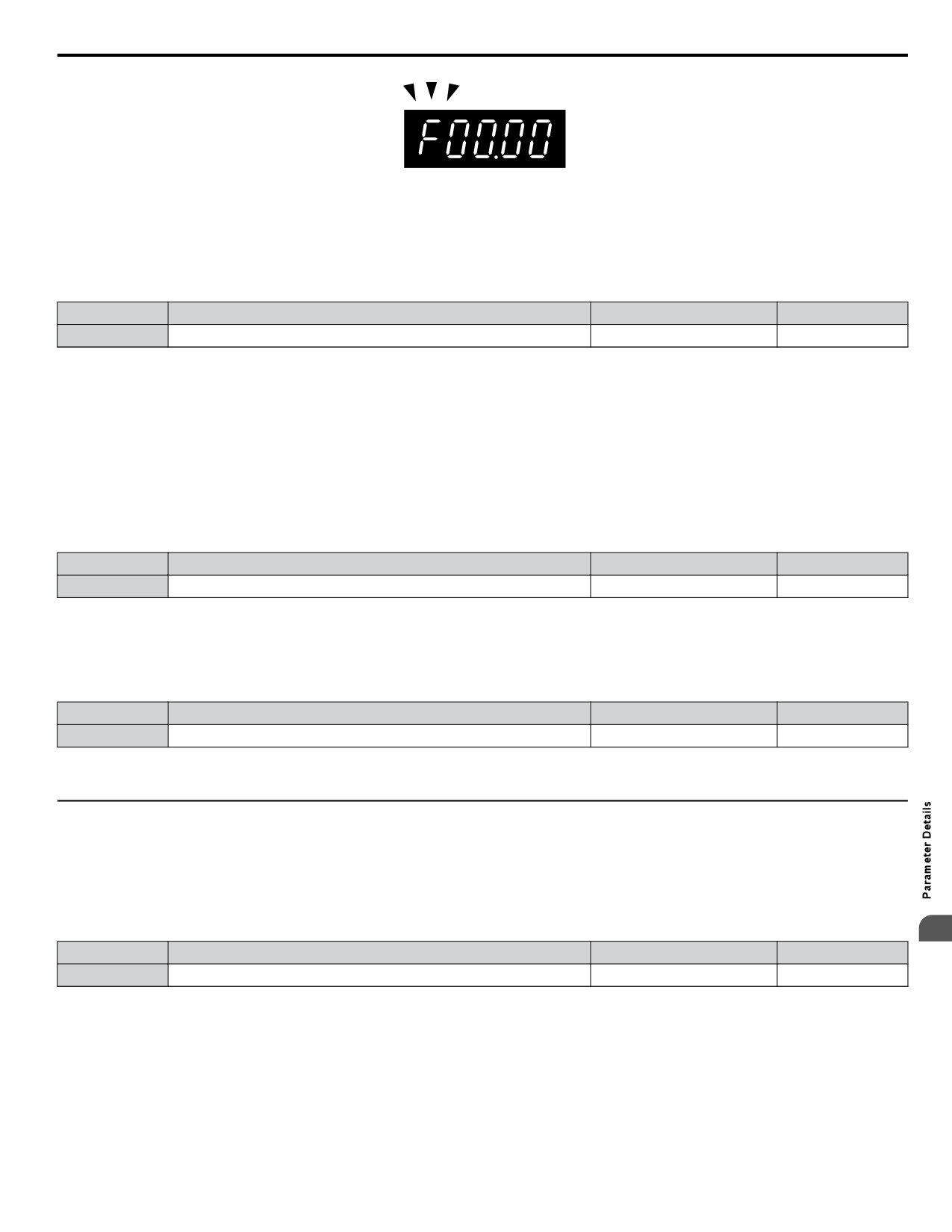
Figure 5.79 Ready to Set Frequency Reference (Standard Digital LED Operator)
n o2-06: Operation Selection when Digital LCD Operator is Disconnected
Determines if the drive will stop when an external LCD operator is removed in LOCAL mode or with b1-02 set to 0.
Note:
An LCD operator is available as an option. This setting is not applicable to the standard LED operator that comes with the drive.
No.
Name
Setting Range
Default
o2-06
Digital Operator Disconnection Operation
0 or 1
0
Setting 0: Continue Operation
The operation is continued.
Setting 1: Trigger a Fault
The operation is stopped and an oPr fault is triggered. The motor coasts to stop.
n o2-07: Motor Direction at Power Up when Using Operator
Determines the direction the motor will rotate after the drive is powered up when the Run command is set to be given from
the digital operator.
Note:
This parameter is effective only when the Run command is set to be given from the digital operator (b1-02/16 = 0).
No.
Name
Setting Range
Default
o2-07
Motor Direction at Power Up when Using Operator
0 or 1
0
Setting 0: Forward
Setting 1: Reverse
n o2-30: Monitor Position Save
No.
Name
Setting Range
Default
o2-30
Monitor Position Save
0, 1
0
Setting 0: Disabled
Setting 1: Enabled
u o3: Copy Function
Use o3 parameters to Read, Copy, and Verify the parameter settings to and from the drive.
n o3-01: Copy Function Selection
This parameter controls the copying of parameters to and from the LED operator (option). The copy function will change
certain parameter default settings depending on the regional specification of the drive.
5
No.
Name
Setting Range
Default
o3-01
Copy Function Selection
0 to 3
0
0: COPY SELECT (no function)
1: INV --> OP READ
All parameters are copied from the drive to the digital operator.
Note:
Set o3-02 to 1 to unlock copy protection.
2: OP --> INV WRITE
All parameters are copied from the digital operator to the drive.
219
5.10 o: Operator Related Settings
3: OP<-->INV VERIFY
Parameter settings in the drive are compared to those in the digital operator.
Note:
When using the copy function, the drive model number (o2-04) and the software number (U1-14) must match or an error will occur.
n o3-02 Copy Allowed Selection
Enables and disables the digital operator copy functions.
No.
Name
Setting Range
Default
o3-02
Copy Allowed Selection
0, 1
0
0: Disabled
No digital operator copy functions are allowed
1: Enabled
Copying allowed
u o4: Maintenance Monitor Settings
n o4-01: Accumulated Operation Time Setting
Parameter o4-01 sets the cumulative operation time and allows the user to set the starting value of the accumulated operation
time displayed in monitor U4-01.
Note:
The value in o4-01 is set in 10 h units. For example, a setting of 30 will set the cumulative operation time counter to 300 h. 300 h will also
be displayed in monitor U4-01.
No.
Name
Setting Range
Default
o4-01
Accumulated Operation Time Setting
0 to 9999
0
n o4-02: Accumulated Operation Time Selection
Selects the conditions for what is to be considered “accumulated operation time.” Accumulated operation time is displayed in
U4-01.
No.
Name
Setting Range
Default
o4-02
Accumulated Operation Time Selection
0 or 1
0
Setting 0: Power On Time
The drive logs the time it is connected to a power supply, no matter if the motor is running or not.
Setting 1: Run Time
The drive logs the time that the output is active, i.e., whenever a Run command is active (even if the motor is not rotating) or
a voltage is output.
n o4-03: Cooling Fan Operation Time/Maintenance Setting
Sets the value of the cooling fan operation time counter displayed in monitor U4-03. Parameter o4-03 also sets the base value
used for the cooling fan maintenance value displayed in U4-04. Be sure to reset this parameter back to 0 if the cooling fan is
replaced.
Note:
1. The value in o4-03 is set in 10 h units. For example, a setting of 30 will set the cooling fan operation time counter to 300 h. “300” will
be displayed in monitor U4-03.
2. The actual maintenance time depends on the environment the drive is used in.
No.
Name
Setting Range
Default
o4-03
Cooling Fan Operation Time
0 to 9999
0
n o4-05: Capacitor Maintenance Setting
Sets value of the maintenance monitor for the DC bus capacitors displayed in U4-05 as a percentage of the total expected
performance life. This value should be reset to 0 when the DC bus capacitors have been replaced.
Note:
The actual maintenance time will depend on the environment the drive is used in.
No.
Name
Setting Range
Default
o4-05
Capacitor Maintenance Setting
0 to 150%
0%
220
5.10 o: Operator Related Settings
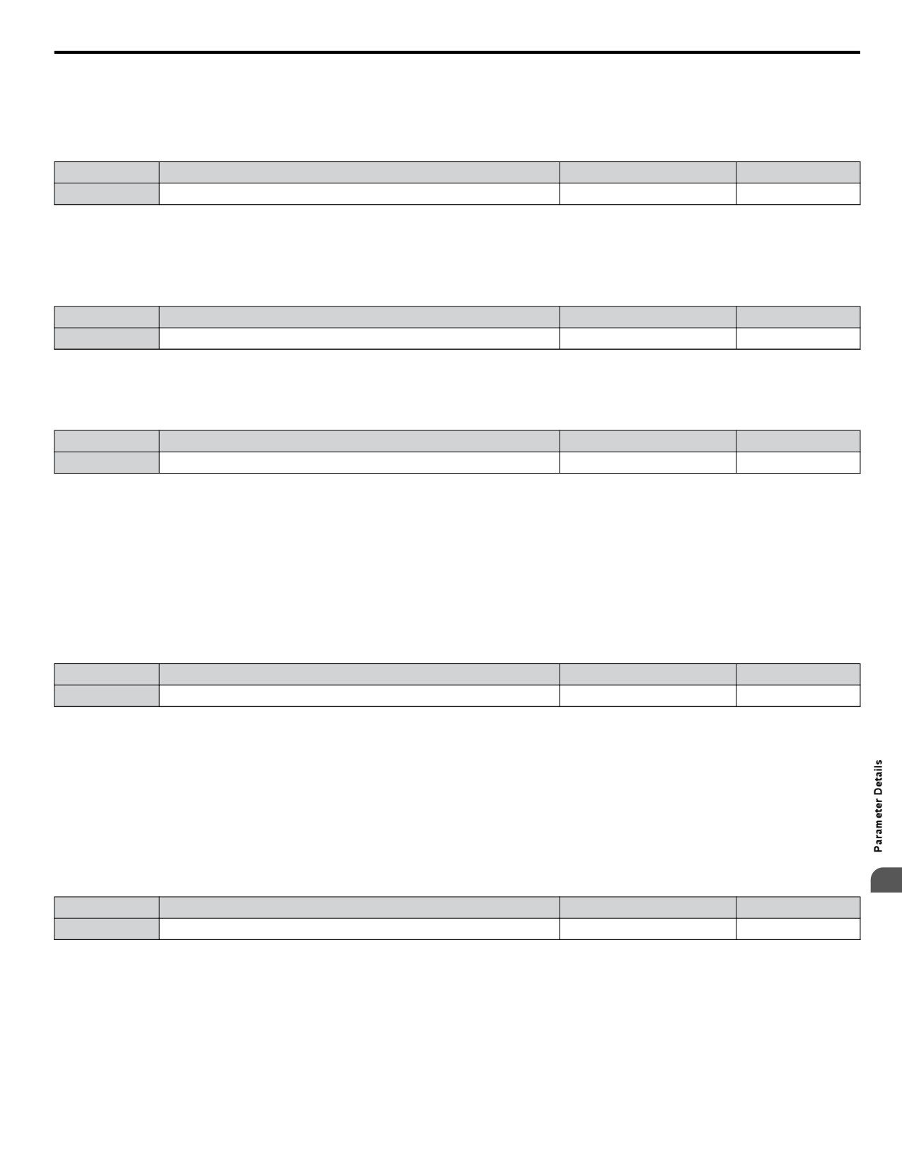
n o4-07: DC Bus Pre-charge Relay Maintenance Setting
Sets the value of the softcharge bypass relay maintenance time displayed in U4-06 as a percentage of the total expected
performance life. This value should be reset to 0 when the relay has been replaced.
Note:
The maintenance actual time depends on the environment the drive is used in.
No.
Name
Setting Range
Default
o4-07
DC Bus Pre-charge Relay Maintenance Setting
0 to 150%
0%
n o4-09: IGBT Maintenance Setting
Sets the value of the IGBT maintenance time displayed in U4-07 as a percentage of the total expected performance life. This
value should be reset to 0 when the IGBTs have been replaced.
Note:
The actual maintenance time depends on the environment the drive is used in.
No.
Name
Setting Range
Default
o4-09
IGBT Maintenance Setting
0 to 150%
0%
n o4-11: U2, U3 Initialization
When the drive is initialized, the fault trace and fault history monitors (U2-oo and U3-oo) are not reset. Parameter o4-11
can be used to initialize them.
No.
Name
Setting Range
Default
o4-11
U2, U3 Initialization
0 or 1
0
Setting 0: No Action
The drive keeps a record of the fault trace and fault history.
Setting 1: Reset Fault Data
Resets the data for the U2-oo and U3-oo monitors. Once o4-11 is set to 1 and the ENTER key is pressed, the fault data
are erased and the display returns to 0.
n o4-12: kWh Monitor Initialization
The kWh monitors U4-10 and U4-11 are not initialized when the power is cycled or the drive is initialized. o4-12 can be used
to manually reset them.
No.
Name
Setting Range
Default
o4-12
kWh Monitor Initialization
0 or 1
0
Setting 0: No Action
The kWh data are kept as they are.
Setting 1: Reset kWh Data
Resets the kWh counter. The monitors U4-10 and U4-11 will show 0. Once o4-12 is set to 1 and the ENTER key is pressed,
the kWh data are erased and the display returns to 0.
n o4-13: Number of Run Commands Counter Initialization
The Run command counter displayed in U4-02 is not reset when the power is cycled or the drive is initialized. Using o4-13
it can be manually reset to 0.
5
No.
Name
Setting Range
Default
o4-13
Number of Run Commands Counter Reset
0 or 1
0
Setting 0: No Action
The Run command data are kept as they are.
Setting 1: Reset Run Commands Counter
Resets the Run commands counter. The monitor U4-02 will show 0. Once o4-13 is set to 1 and the ENTER key is pressed,
the counter value is erased and the display returns to 0.
221
5.10 o: Operator Related Settings
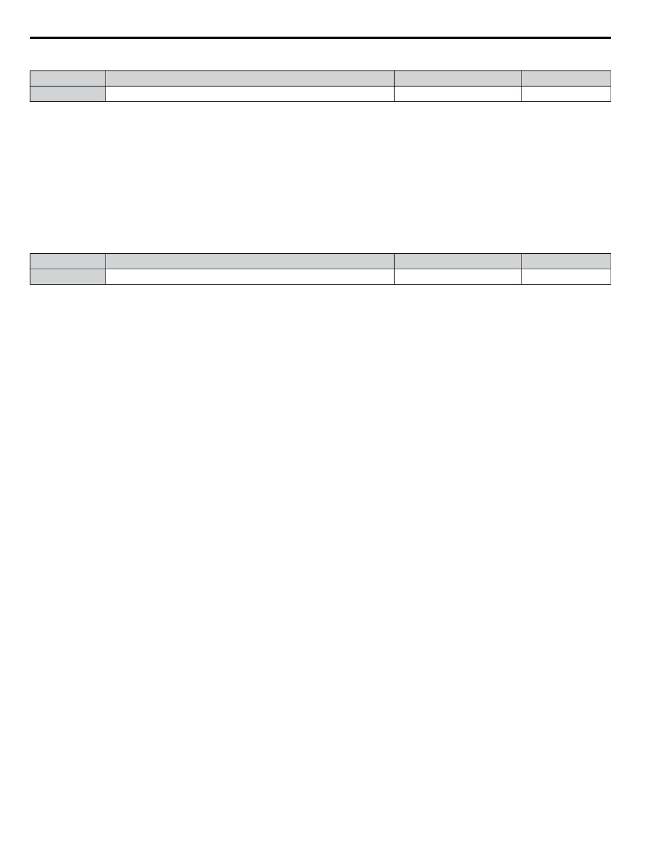
n o4-17: Real-Time Clock Setting
No.
Name
Setting Range
Default
o4-17
Set/Reset Real-Time Clock
0 to 2
0
Setting 0: — —
No Setting (Default)
Setting 1: Set
When o4-17 is set to 1, the digital operator will show the Clock Adjustment display. In Clock Adjustment Mode the user can
adjust the Real-Time Clock.
Setting 2: Reset
When o4-17 is set to 2, the Real-Time Clock data is cleared. A TIM fault will occur until o4-17 is set to 1 and the Real-Time
Clock is set.
n o4-20: Time Display Format
No.
Name
Setting Range
Default
o4-20
Time Display Format
0, 1
0
Sets the time display format.
Setting 0: 12-Hour
Setting 1: 24-Hour
222
5.11 P: Pump
5.11 P: Pump
u P1: Pump Basic
n P1-01: Pump Mode
Selects the base operation mode of the drive controller.
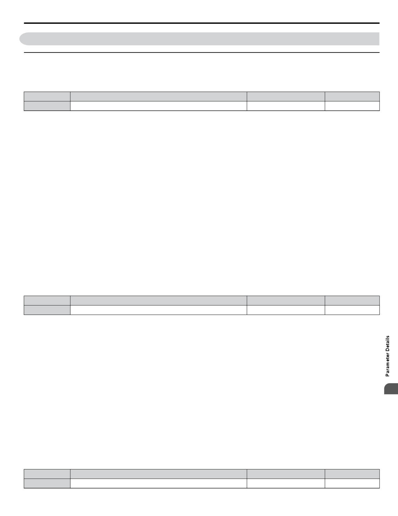
No.
Parameter Name
Setting Range
Default
P1-01
Pump Mode
0, 3
0
Setting 0: Drive only
Designed for single pump stand-alone applications
Setting 3: MEMOBUS network
Up to eight drives can be networked together to provide for system redundancy and precise control.
Staging is disabled when and the drive PID output is influenced by the Water Level / Suction Pressure Control.
The functions listed below will behave slightly different when P1-01 is set to 3:
• Start Level: Active on the first pump in the network. Drives in the process of alternation will not undergo this process.
• Sleep: Active when the drive is the only drive running on the network.
• Over-cycle Protection: Active when the drive is the only drive running on the network.
• Pre-charge: Active only on the first drive to run in the network.
• Low City Pressure: Active on any drive in the network. An alarm condition will cause other drives in the network to stop
running and show a “Net Pump Err” message.
• Utility Delay: When this function is active, the drive is unavailable to the iQpump MEMOBUS Network and will force the
Home Screen text to show “Pump Off Network”.
• Remote Drive Disable: When this function is active, the drive is unavailable to the iQpump MEMOBUS Network and will
force the Home Screen text to show “Pump Off Network”.
n P1-02: System Units
Selects the base unit in which most drive PID setpoints, scaling, monitors, limits, and faults/alarm levels will be set.
Note:
Set this parameter prior to changing other parameters, as internal scaling is based on P1-02.
No.
Parameter Name
Setting Range
Default
P1-02
System Units
0 to 10
1
Setting 0: No unit
Setting 1: PSI: Pounds per square inch
Setting 2: Pa: Pascals
Setting 3: Bar: Bar
Setting 4: "WC: Inch of water
Setting 5: "Hg: Inch of Mercury
Setting 6: ft: feet
Setting 7: m: meters
5
Setting 8: °F: Degrees Fahrenheit
Setting 9: °C: Degrees Celsius
Setting 10: Percent
n P1-03: Feedback Device Scaling
Sets the feedback device scaling used for the PID controller. This information can be found on the nameplate or specification
sheet and is usually expressed as the maximum output of the device.
For example, a pressure sensor scaling might be 145.0 PSI at 20 mA output and would require setting P1-03 to 145.0 PSI.
Note:
Set this parameter prior to changing other parameters related to the PID feedback, as internal scaling is based on P1-03.
No.
Parameter Name
Setting Range
Default
P1-03
Feedback Device Scaling
0.1 to 6000.0
145.0 PSI
223
5.11 P: Pump
n P1-04: Start / Draw Down Level
Sets the wake up level from the Sleep function. This setting is dependent on whether PID is normal or inverse acting (b5-09).
When the drive is asleep and the PID feedback signal rises above (normal acting) or falls below (inverse acting) this setting
for the time set in P1-05, Start Level Delay Time, the drive will wake up.
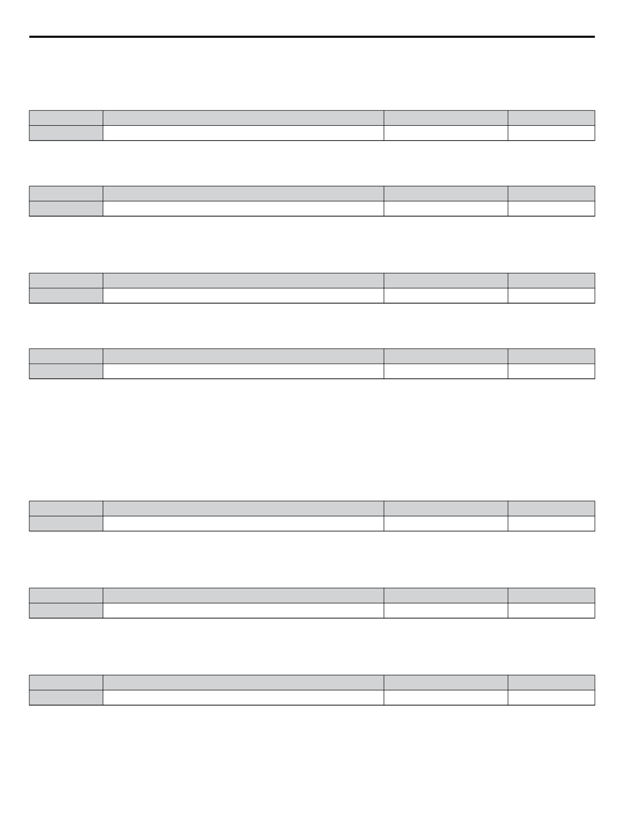
No.
Parameter Name
Setting Range
Default
P1-04
Start / Draw Down Level
-999.9 to 999.9
0.0 PSI
n P1-05: Start Level Delay Time
Sets the delay time for waking the drive to prevent accidental wake up caused by erratic feedback.
No.
Parameter Name
Setting Range
Default
P1-05
Start Level Delay Time
0 to 3600 s
1 s
n P1-06: Minimum Pump Speed
Sets the minimum speed at which the drive will run the pump. Most pumps cannot run at low speeds due to cavitation, so be
sure to consult the pump specification sheet for the minimum safe run speed.
No.
Parameter Name
Setting Range
Default
P1-06
Minimum Pump Speed
0.0 to E1-04
40.0 Hz
n P1-07: Minimum Pump Speed Units
Sets the units, range, and resolution for parameter P1-06. Changing P1-07 resets P1-06 to the default value.
No.
Name
Setting Range
Default
P1-07
Minimum Pump Speed Units
0, 1
0
Setting 0: Hz
Forces a default value of 40.0 Hz for P1-06.
Setting 1: RPM
Forces a default value of 1800 RPM (VTC) and 2400 RPM (all others) for P1-06.
n P1-08: Low Feedback Level
Sets the level at which a Low Feedback alarm or fault will occur. When the PID feedback falls below the P1-08 setting for
the time set in P1-09, the drive will respond based on the setting in P1-10.
No.
Parameter Name
Setting Range
Default
P1-08
Low Feedback Level
0.0 to 6000.0
0.0 PSI
n P1-09: Low Feedback Level Fault Delay Time
Sets the delay time after which a Low Feedback alarm or fault will occur. When the PID feedback falls below the P1-08 setting
for the time set in P1-09, the drive will respond based on the setting in P1-10.
No.
Parameter Name
Setting Range
Default
P1-09
Low Feedback Level Fault Delay Time
0 to 3600 s
10 s
n P1-10: Low Feedback Selection
Selects the drive response to a Low Feedback condition. When the PID feedback falls below the P1-08 setting for the time set
in P1-09, the drive will respond based on the setting in P1-10.
No.
Parameter Name
Setting Range
Default
P1-10
Low Feedback Selection
0 to 2
0
Low feedback detection is enabled when:
• P1-08 > 0.0
• Drive is running in AUTO Mode, including sleep boost and feedback drop detection (standard PID, b5-09 = 0)
• Run Command is present (including sleep and timer operation) (inverse PID, b5-09 = 1)
224
5.11 P: Pump
Setting 0: Fault
When feedback drops below the P1-08 level for longer than the time set in P1-09, the drive will fault on the “LFB - Low
Feedback” fault and coast to a stop.
The digital output programmed to “Low Feedback” (H2-0o = 97) closes. The drive will also display the “Low Feedback -
Low FB Sensed” alarm. The digital output will remain closed until the fault is reset.
Setting 1: Alarm
When feedback drops below the P1-08 level for longer than the time set in P1-09, the digital output programmed to “Low
Feedback” (H2-0o = 97) closes and the drive displays the “Low Feedback - Low FB Sensed” alarm.
When feedback rises above the level determined by P1-08 and P1-14, or when one or more of the conditions that enable low
feedback detection are no longer true, the digital output will open and the alarm will clear.
Setting 2: Digital out only
When feedback drops below the P1-08 level for longer than the time set in P1-09, the digital output programmed to “Low
Feedback” (H2-0o = 97) closes.
When feedback rises above the level determined by P1-08 and P1-14, or when one or more of the conditions that enable low
feedback detection are no longer true, the digital output will open.
n P1-11: High Feedback Level
Sets the level at which a High Feedback alarm or fault will occur. When the PID feedback rises above the P1-11 setting for
the time set in P1-12, the drive will respond based on the setting in P1-13.
No.
Parameter Name
Setting Range
Default
P1-11
High Feedback Level
0.0 to 6000.0
155.0 PSI
n P1-12: High Feedback Level Fault Delay Time
Sets the delay time after which a Low Feedback alarm or fault will occur. When the PID feedback rises above the P1-11 setting
for the time set in P1-12, the drive will respond based on the setting in P1-13.
No.
Parameter Name
Setting Range
Default
P1-12
High Feedback Level Fault Delay Time
0 to 3600 s
5 s
n P1-13: High Feedback Selection
Selects the drive response to a High Feedback condition. When the PID feedback rises above the P1-11 setting for the time
set in P1-12, the drive will respond based on the setting in P1-13.
No.
Parameter Name
Setting Range
Default
P1-13
High Feedback Selection
0 to 2
0
High feedback detection is enabled when:
• P1-11 > 0
• Run Command present, including sleep & timer operation (standard PID, b5-09 = 0)
• Drive is running in AUTO Mode, including feedback drop detection (inverse PID, b5-09 = 1).
Setting 0: Fault
When feedback rises above the P1-11 for longer than the time set in P1-12, the drive will fault on the “HFB - High Feedback”
fault and coast to a stop.
5
The digital output programmed to “High Feedback” (H2-0o= 96) closes. The drive will also display the “High Feedback -
High FB Sensed” alarm. The digital output will remain closed until the fault is reset.
Setting 1: Alarm
When feedback rises above the P1-11 for longer than the time set in P1-12, the digital output programmed to “High Feedback”
(H2-0o= 96) closes and the drive displays the “High Feedback - High FB Sensed” alarm.
When feedback falls below the level determined by P1-11 and P1-14, or when one or more of the conditions that enable high
feedback detection are no longer true, the digital output will open and the alarm will clear.
Setting 2: Digital out only
When feedback rises above the P1-11 for longer than the time set in P1-12, the digital output programmed to “High Feedback”
(H2-0o= 96) closes.
225
5.11 P: Pump
When feedback falls below the level determined by P1-11 and P1-14, or when one or more of the conditions that enable high
feedback detection are no longer true, the digital output will open.
n P1-14: Hysteresis Level
Sets the hysteresis level used for low and high feedback detection.
No.
Name
Setting Range
Default
P1-14
Hysteresis Level
0.0 to 100.0
0.0 PSI
n P1-15: Maximum Setpoint Difference
When the system is running and the difference between the setpoint and feedback exceeds the level set in P1-15 for the time
set in P1-16, the drive will respond according to the method selected in P1-17. On fault, the drive will coast to stop.
Setting this parameter to 0.0 disables the function. This function is active only when running while in AUTO Mode. When
P1-01 is set to 3, the function is active on the lead drive and will stop all drives running on the network when the NMS fault
occurs (system fault).
No.
Name
Setting Range
Default
P1-15
Maximum Setpoint Difference
0.0 to 6000.0
0.0 PSI
n P1-16: Not Maintaining Setpoint Time
Sets the delay time before a “Setpoint Not Met” condition occurs. Pump protection criteria specified in P1-15 must be met
before the timer will start. Setting P1-15 to 0 disables NMS detection.
No.
Name
Setting Range
Default
P1-16
Not Maintaining Setpoint Time
0 to 3600 s
60 s
n P1-17: Not Maintaining Setpoint Selection
No.
Name
Setting Range
Default
P1-17
Not Maintaining Setpoint Selection
0 to 2
0
Setting 0: Fault
The “NMS - Setpoint Not Met” alarm is shown on the HOA keypad and the digital output closes when the PID feedback rises
above or falls below the setpoint for more than the P1-15 amount.
When the feedback returns to a value within the P1-15 setting before the Not Maintaining Set Point Time (P1-16) expires, the
alarm clears, the digital output opens, and the timer resets. If the NMS condition persists for longer than the time set in P1-16,
the drive will fault out on a “NMS - Setpoint Not Met” fault and coast to a stop. The digital output remains closed until the
fault is reset.
Setting 1: Alarm
The “NMS - Setpoint Not Met” alarm is shown on the HOA keypad and the digital output closes when the PID feedback rises
above or falls below the setpoint more than the P1-15 amount.
When the feedback returns to a value within the P1-15 level, the alarm clears and the digital output opens.
Setting 2: Digital out only
A digital output programmed to 93 closes. When the feedback returns to a value within the P1-15 level, the digital output
opens.
n P1-18: Prime Loss Detection Method
No.
Name
Setting Range
Default
P1-18
Prime Loss Detection Method
0 to 2
0
Loss of Prime (LOP) is enabled when one of the following conditions are true:
• P1-19 > 0 in AUTO Mode and Sleep Boost
• P4-05 > 0 in Pre-Charge 1 Mode
• P4-08 > 0 in Pre-Charge 2 Mode
• P5-06 > 0 in HAND Mode
• P5-07 > 0 in HAND Mode 2
226
5.11 P: Pump
• b5-14 > 0 in Wire Break (Run at Fixed Speed Mode)
The drive detects an LOP condition when the output frequency rises above the LOP detection frequency, and the measured
quantity (current, power, or torque) falls below the LOP detection level.
When the condition is detected for longer than the time set in P1-20, Prime Loss Time, the drive will respond according to the
P1-22, Prime Loss Selection, setting.
Setting 0: Current (A)
U1-03, Output Current, is compared against LOP detection level parameters P1-19, P4-05, P4-08, P5-06, P5-07, and b5-14.
The unit text of the LOP Detection Level parameters is A (Amps).
Setting 1: Power (kW)
U1-08, Output Power, is compared against LOP detection level parameters P1-19, P4-05, P4-08, P5-06, P5-07, and b5-14.
The unit text of the LOP Detection Level parameters is kW.
Setting 2: Torque (%)
The drive calculated torque (U6-01, Motor Secondary Current (Iq in V/f) is compared against LOP detection level parameters
P1-19, P4-05, P4-08, P5-06, P5-07, and b5-14. The unit text of the LOP Detection Level parameters is percentage (%).
n P1-19: Prime Loss Level
Detects loss of prime in the pump when in AUTO or Sleep Boost mode. If the measured quantity determined by P1-18 drops
below this level for the time specified in P1-20 and the output frequency is above the level determined by P1-21, a “Loss Of
Prime” condition occurs. The drive will respond to the “Loss Of Prime” condition based on the P1-22 setting.
No.
Name
Setting Range
Default
P1-19
Prime Loss Level
0.0 to 1000.0 A
0.0 A
n P1-20: Loss of Prime Time
Sets the delay time before a “Loss of Prime” condition occurs. The pump protection criteria specified in P1-18 and P1-19 must
be met before the timer will start.
No.
Name
Setting Range
Default
P1-20
Loss of Prime Time
0 to 600 s
20 s
n P1-21: Loss of Prime Frequency
If P1-21 is set to a non-zero value, when the drive is operating above the frequency set in this parameter, the “Loss Of Prime”
detection is enabled. If this parameter is set to zero, the frequency level will be determined by the smaller value between (Fmax
- 1 Hz) and (d2-01 - 1 Hz).
No.
Name
Setting Range
Default
P1-21
Loss of Prime Frequency
0.0 to [E1-04]
0.0 Hz
n P1-22: Loss of Prime Selection
Determines drive response to a “Loss Of Prime” condition.
No.
Name
Setting Range
Default
P1-22
Loss of Prime Selection
0 to 2
0
Setting 0: Fault
5
Setting 1: Alarm
Setting 2: Digital out only
n P1-23: Loss of Prime Maximum Restart Time
If the Loss of Prime fault restart fails (or is not attempted due to a continuing fault condition), the drive will wait for the time
set in P1-23 before attempting another restart.
Note:
This parameter will take the place of L5-04 during a Loss of Prime fault restart attempt.
No.
Name
Setting Range
Default
P1-23
Loss of Prime Maximum Restart Time
0.2 to 6000.0 min
0.2 min
227
5.11 P: Pump
n P1-24: Level at Full Speed
Sets the level used to override the P-gain and I-limit with a calculated value based on Sleep level, Wakeup level, Minimum
Pump Speed, Transducer Scaling, and Maximum Frequency. This feature is disabled when set to 0.0.
No.
Name
Setting Range
Default
P1-24
Level at Full Speed
0.0 to 6000.0
0.0
n P1-30: Low Water Digital Input Configuration
The low water level digital input can indicate when a low water (low level or low pressure) condition exists and fault out the
drive. The “Low Water Level” fault is only active when the drive is in an AUTO run state, including sleep boost and feedback
drop detection. The fault is not active in all other modes (Sleep, HAND Mode, Pre-Charge, Run at Wire Break, and Sleep).
The low water level digital input can also indicate the end of the Pre-Charge function. The Pre-Charge runs until the low water
indication is no longer active.
No.
Name
Setting Range
Default
P1-30
Low Water Digital Input Configuration
0, 1
0
Setting 0: Normally open
Closing the switch during an AUTO Mode run triggers the “LWL - Low Water Level” fault and the drive coasts to a stop.
Pre-Charge continues while the switch is closed and ends when it opens.
Setting 1: Normally closed
Opening the switch during an AUTO mode run triggers the “LWL - Low Water Level” fault and the drive coasts to a stop.
Pre-Charge continues while the switch is open and ends when it closes.
n P1-31: High Water Digital Input Configuration
The high water level digital input indicates if a high water (high level or pressure) condition exists and faults out the drive.
The “High Water Fault” is only active when the drive is running the pump. The fault is not active when the drive is stopped
or sleeping.
No.
Name
Setting Range
Default
P1-31
High Water Digital Input Configuration
0, 1
0
Setting 0: Normally open
Closing the switch while the drive is running will trigger the “HWL - High Water Level” fault and the drive will coast to a
stop.
Setting 1: Normally closed
Opening the switch while the drive is running will trigger the “HWL - High Water Level” fault and the drive will coast to a
stop.
u P2: Pump Protection
n P2-01: Sleep Level Type
Selects which data source the drive will use to determine if it should activate the sleep function. This parameter is application-
dependent and should be set in conjunction with the type of system data is available. Choose the data type that best represents
a low-activity condition for the system.
Note:
Set this parameter prior to changing other parameters related to the Sleep Function, as internal scaling is based on P2-01.
No.
Parameter Name
Setting Range
Default
P2-01
Sleep Level Type
0 to 3
0
Setting 0: Output frequency
Setting 1: Output current
Setting 2: Feedback
Setting 3: Output speed (RPM)
n P2-02: Sleep Level
Sets the level at which the drive will enter sleep mode. The drive will enter sleep mode when the monitored data falls below
the P2-02 setting for the time set in P2-03.
228
5.11 P: Pump
No.
Parameter Name
Setting Range
Default
P2-02
Sleep Level
0.0 to 6000.0
0.0 Hz
n P2-03: Sleep Delay Time
Sets the delay time after which the drive will enter sleep mode. The drive will enter sleep mode when the monitored data falls
below the P2-02 setting for the time set in P2-03.
No.
Parameter Name
Setting Range
Default
P2-03
Sleep Delay Time
0 to 3600 s
5 s
n P4-01: Pre-Charge Level
Sets the level at which the drive will activate the pre-charge function. At start, if the PID is below the P4-01 setting, the drive
will run at the P4-02 frequency setting for the time set in P4-03. PID control is delayed until the Pre-charge function stops.
The drive will exit the pre-charge function early if the feedback rises above the P4-01 setting or if a Low Water digital input
switch (H1-oo = 8F) deactivates. Pre-charge is useful to slowly fill or pressurize a system.
No.
Parameter Name
Setting Range
Default
P4-01
Pre-Charge Level
0.0 to 6000.0
0.0 PSI
n P4-02: Pre-Charge Frequency
Sets the frequency at which the pre-charge function will run.
No.
Parameter Name
Setting Range
Default
P4-02
Pre-Charge Frequency
0.0 to E1-04
0.0 Hz
n P4-03: Pre-Charge Time
Sets the duration of time that the Pre-Charge function will run.
No.
Parameter Name
Setting Range
Default
P4-03
Pre-Charge Time
0.0 to 3600.0 min
0.0 min
The following conditions must be met to enter Pre-Charge Mode:
• Drive Ready or Sleeping (Run command, not faulted, not in program mode)
• NOT in HAND Mode
•
“Disable Pre-charge” digital input NOT closed
• P4-03 > 0.0
• If P4-01, Pre-Charge Level, is greater than 0, the PID feedback must be below the P4-01 level. (Forward acting PID, b5-09
= 0, Reverse acting PID, b5-09 = 1).
When the drive enters Pre-Charge Mode 1 and 2, the drive runs at the Pre-Charge frequency set in P4-02/P4-06, the PID
controller is disabled and the Pre-Charge digital output (H2-0o = A4) closes.
When pre-charge is active, the message “Pre Chg Mode Exit in Xsec” appears on the keypad to show how long before pre-
charge exits via timers (P4-03 + P4-07).
Additionally, during Pre-Charge Mode:
• When Pre-charge Level 2 (P4-32) is set to 0, the system can exit Pre-charge when the PID Feedback goes above the Pre-
charge Level (P4-01) in normal PID operation, or below the P4-01 level in inverse PID operation.
5
However, when Pre-charge Level 2 (P4-32) is set to a non-zero value, the system goes into Pre-Charge 2 instead when Pre-
Charge 1 completes via timer (P4-03) or level (P4-01). At this point, the drive will run at Pre-charge Frequency 2 (P4-06).
The system can exit Pre-charge 2 when the PID Feedback goes above the Pre-charge Level 2 (P4-32) in normal PID operation,
or below the P4-32 level in inverse operation.
• When P4-02, Pre-Charge Frequency, or P4-06, Pre-Charge Frequency 2, are set to a value less than P1-06, Minimum Pump
Speed, the alarm “Freq. Ref < Pump Min P1-06” is displayed and the drive runs at the minimum speed.
• When Pre-Charge Loss of Prime parameters P4-05 and P4-08 are set to 0, the Loss of Prime detection is disabled.
• When Pre-Charge Loss of Prime parameters P4-05 or P4-08 are set to a value greater than 0, Loss of Prime detection will
operate after the output speed reaches the Pre-Charge Frequency set in P4-02 or P4-06.
• The “Low Water” fault (H1-0o = 8F) is disabled.
229
5.11 P: Pump
• The “Low Feedback” fault is disabled when forward-acting PID is selected (b5-09 = 0) and the “High Feedback” fault is
disabled when reverse-acting PID is selected (b5-09 = 1).
• The “Not Maintaining Setpoint” fault is disabled.
• The “Feedback Loss” detection (4 to 20 mA wire break) is enabled, however, the Pre-Charge frequencies will override and
the b5-13 “feedback loss goto speed”.
The drive will always exit Pre-Charge Mode when Pre-Charge times P4-03 and P4-07 have expired. The drive will also exit
Pre-Charge Mode when one of the following conditions are met:
• P4-03 and P4-32 are set to 0.0
• The “Disable Pre-Charge” digital input (H1-0o = 8C) closes.
• A digital input programmed to “Low Water” (H1-0o = 8F) is deactivated (open when P1-30 = 0 or closed when P1-30 =
1).
• The PID feedback satisfies both Pre-charge levels 1 and 2 (all must be true):
Pre-charge timers P4-03 and P4-07 have NOT expired
PID is enabled (b5-01 > 0).
PID is NOT disabled via digital input
Pre-Charge Level Set (P4-01 > 0) (and if used, P4-32 > 0)
Feedback is greater than Pre-Charge Level (P4-01) and Pre-charge Level 2 (P4-32) (forward-acting PID, b5-09 = 0) or less
than Pre-Charge Levels 1 and 2 (reverse-acting PID, b5-09 = 1)
Drive is NOT in a “Feedback Loss” condition (4 to 20 mA wire-break detection).
n P2-04: Sleep Activate Level
When P2-01, Sleep Level Type, is set to 0 (Output Frequency / Speed), the Sleep function activates when the output frequency
is greater or equal to the level set in P2-04. When P2-04 is programmed to 0.0, the Sleep function activates above P2-02, Sleep
Level.
No.
Name
Setting Range
Default
P2-04
Sleep Activate Level
0.0 to 6000.0
0.0 Hz
n P2-05: Sleep Boost Level
Sets the amount of boost applied to the setpoint prior to going to sleep. A setting of 0.0 disables the sleep boost function.
No.
Name
Setting Range
Default
P2-05
Sleep Boost Level
0.0 to 6000.0
0.0 PSI
n P2-06: Sleep Boost Hold Time
Sets the amount of time the boosted pressure will be maintained before the drive goes to sleep.
No.
Name
Setting Range
Default
P2-06
Sleep Boost Hold Time
0.5 to 160.0 s
5.0 s
n P2-07: Sleep Boost Maximum Time
Sets the amount of time the system (feedback) has to reach the boosted setpoint. The drive goes to sleep when the amount of
time set in P2-07 is exceeded.
No.
Name
Setting Range
Default
P2-07
Sleep Boost Maximum Time
0.5 to 160.0 s
5.0 s
n P2-08: Delta Sleep Feedback Drop Level
When the drive enters sleep mode, the software monitors the feedback to detect a flow-no flow condition. When the PID error
(setpoint minus feedback) exceeds the level set in P2-08 within the time set in P2-09 and the output frequency exceeds the
P1-06 setting, the sleep operation deactivates and the drive returns to normal operation.
No.
Name
Setting Range
Default
P2-08
Delta Sleep Feedback Drop Level
0.0 to 6000.0
0.0 PSI
230
5.11 P: Pump
n P2-09: Feedback Detection Drop Time
Sets the time window in which the software monitors the feedback to detect a flow-no flow condition using parameter P2-08.
No.
Name
Setting Range
Default
P2-09
Feedback Detection Drop Time
0.0 to 3600.0 s
10.0 s
n P2-10: Sleep Mode: Cycling Protection
Sets the maximum number of cycles allowed within the time specified in P2-11 before system faults on a PCF “Pump Cycle
Fault”.
One cycle is defined as when the drive transfers from normal operation to sleep mode while in AUTO Mode.
A value of 0 disables this function. If P1-01 is set to 3, the function is active when there is only one drive running in the
network.
No.
Name
Setting Range
Default
P2-10
Sleep Mode: Cycling Protection
0 to 10
0
n P2-11: Sleep Mode: Maximum Cycling Protection Time
Sets the maximum time allowed between cycles. When no cycling occurs within the time programmed in P2-11, the drive will
decrease the internal cycle register.
No.
Name
Setting Range
Default
P2-11
Sleep Mode: Maximum Cycling Protection Time
0 to 3600 s
300 s
n P2-12: Over Cycling Mode
Selects the mode and response to an over-cycling condition.
No.
Name
Setting Range
Default
P2-12
Over Cycling Mode
0 to 3
0
Setting 0: Disabled
Setting 1: Alarm
Setting 2: Fault
Setting 3: Auto SP Compensation
n P2-13: Setpoint Compensation
Sets the amount the drive will increase the setpoint after each over-cycle in an effort to stop the drive from sleeping too often.
When P2-12 is set to 3 (Auto SP Compensation), the software automatically adjusts the setpoint when over-cycling is detected.
No.
Name
Setting Range
Default
P2-13
Setpoint Compensation
0.0 to 6000.0
0.0 PSI
n P2-14: Maximum Setpoint Compensation
Sets the maximum allowed setpoint compensation for the Auto Setpoint Compensation mode (P2-12 = 3).
No.
Name
Setting Range
Default
5
P2-14
Maximum Setpoint Compensation
0.0 to 6000.0
0.0 PSI
n P2-23: Anti-No-Flow Bandwidth
Sets the amount of PI “Error” bandwidth used to detect the no-flow condition. Operation can become less stable if this value
is set too high. A setting of 0.00% disables this feature.
No.
Name
Setting Range
Default
P2-23
Anti-No-Flow Bandwidth
0.00 to 2.00%
0.40%
n P2-24: Anti-No-Flow Detection Time
Sets the time delay after Anti-No-Flow is detected before the drive begins an increased deceleration rate.
231
5.11 P: Pump
No.
Name
Setting Range
Default
P2-24
Anti-No-Flow Detection Time
1.0 to 60.0 s
10.0 s
n P2-25: Anti-No-Flow Release Level
Sets the amount below the setpoint that the feedback must drop after the Anti-No-Flow activates to disengage the Anti-No-
Flow and return to normal PI operation.
No.
Name
Setting Range
Default
P2-25
Anti-No-Flow Release Level
0.0 to 100.0
3.0 PSI
u P4: Pump Advanced
n P4-05: Pre-Charge Loss of Prime Level
Sets the level used to detect loss of prime in the pump.
No.
Name
Setting Range
Default
P4-05
Pre-Charge Loss of Prime Level
0.0 to 1000.0
0.0 A
If the measured quantity set in P1-18 drops below the level set in P4-05 for the time specified in P1-20 and the output frequency
is at the P4-02 level, a “Loss Of Prime” condition occurs. The drive will respond to the “Loss Of Prime” condition based on
P1-22 setting.
n P4-06: Pre-Charge Frequency 2
Sets the frequency reference used when the Pre-Charge 2 function is active. A value of 0.00 disables this function.
No.
Name
Setting Range
Default
P4-06
Pre-Charge Frequency 2
0.0 to [E1-04]
0.0 Hz
n P4-07: Pre-Charge Time 2
Sets the amount of time the drive will spend at the P1-06 Pre-Charge Frequency 2 speed during Pre-Charge 2. A value of 0.0
disables this function.
No.
Name
Setting Range
Default
P4-07
Pre-Charge Time 2
0.0 to 3600.0 min
0.0 min
n P4-08: Pre-Charge Loss of Prime Level 2
Sets the level used to detect loss of prime in the pump.
No.
Name
Setting Range
Default
P4-08
Pre-Charge Loss of Prime Level 2
0.0 to 1000.0
0.0 A
If the measured quantity set in P1-18 drops below the level set in P4-08 for the time specified in P1-20 and the output frequency
is at the P4-06 level, a “Loss Of Prime” condition occurs. The drive will respond to the “Loss Of Prime” condition based on
P1-22 setting.
n P4-10: AUTO Mode Operator Run Power Down Storage
Selects drive response to power loss with regards to the Run command. When running in AUTO Mode and using a Run
command from the keypad (b1-02 = 0), P4-10 determines whether the drive will automatically start running when power is
reapplied. The factory setting of this parameter requires pressing the AUTO key to start the drive after power loss.
WARNING! Sudden Movement Hazard. If the drive is running at power loss, it will automatically initiate an internal Run command upon
power-up if P4-10 = 1 (Enabled) and could result in death or serious injury from moving equipment.
No.
Parameter Name
Setting Range
Default
P4-10
AUTO Mode Operator Run Power Down Storage
0, 1
0
Setting 0: Disabled
Setting 1: Enabled
n P4-11: Thrust Bearing Acceleration Time
Setst he amount of time that the drive will accelerate from 0 speed to the value set in P4-12.
232
5.11 P: Pump
No.
Name
Setting Range
Default
P4-11
Thrust Bearing Acceleration Time
0.0 to 600.0 s
1.0 s
While this parameter is active, the drive will display the message “Thrust Mode - Thrust Active” on the keypad and the digital
output associated with thrust mode (H2-0o = A9) will close. For output frequencies above P4-12, the drive standard
acceleration rates will apply and the message and digital output will clear. When this parameter is set to 0.0, the drive will use
the standard acceleration rate.
n P4-12: Thrust Bearing Frequency
Sets the frequency used by the drive when determining which acceleration and deceleration time to use. The Thrust Bearing
function is used for applications using submersible motors. The function provides an alternate acceleration time (P4-11) and
deceleration time (P4-13) for protecting the pump bearings.
At start, the drive will use the P4-11 acceleration time until the P4-12 frequency is reached, at which time it will use the active
C1-oo acceleration and deceleration times. At stop, if the output frequency is above the P4-12 setting, the active C1-oo
deceleration time will be used until the P4-12 setting is reached at which time it will use the P4-13 time setting for the rest of
deceleration.
If P4-12 is set greater than P1-06 (minimum Pump Speed), P4-12 will become the frequency lower limit. The drive PID control
must be disabled (b5-01 = 0) for this function to work.
No.
Parameter Name
Setting Range
Default
P4-12
Thrust Bearing Frequency
0.0 to E1-04
30.0 Hz
n P4-13: Thrust Bearing Deceleration Time
Specifies the amount of time that the drive will decelerate from the value set in P4-12 until reaching 0.
No.
Name
Setting Range
Default
P4-13
Thrust Bearing Deceleration Time
0.0 to 600.0 s
5.0 s
While this parameter is active, the drive will display the message “Thrust Mode - Thrust Active” on the keypad and the digital
output associated with thrust mode (H2-0o = A9) will close. For output frequencies above P4-12, the drive standard
deceleration rates apply and the message and digital output will clear. When this parameter is set to 0.0, the drive will use the
standard deceleration rate.
n P4-17: Utility Start Delay
Sets the delay time after power up until the drive will recognize a Run command present within one second of power up or
when the Run command is jumpered on the terminal strip.
This is useful in preventing a peak power surge when multiple drives power up and begin accelerating simultaneously. This
function works when the drives all have different P4-17 settings to spread out the power draw during acceleration.
If the Run command is removed and re-applied during the P4-17 time, the drive will cancel the utility start delay and
immediately begin running.
The Utility Start Delay is applied when the drive is auto-restarting after an Undervoltage (Uv) or an Overvoltage (ov) condition.
No.
Parameter Name
Setting Range
Default
P4-17
Utility Start Delay
0.0 to 1000.0 min
0.2 min
n P4-21: Low City Input Select
5
Selects the type of pressure switch connected to the “Low City Press” digital input (H1-0o = 73).
No.
Name
Setting Range
Default
P4-21
Low City Input Select
0, 1
1
Setting 0: Normally open
Setting 1: Normally closed
n P4-22: Low City On-Delay Time
Sets the amount of time a “Low City Pressure” condition must be present before the drive will stop.
No.
Name
Setting Range
Default
P4-22
Low City Input On-Delay Time
1 to 1000 s
10 s
233
5.11 P: Pump
n P4-23: Low City Off-Delay Time
Sets the amount of time a “Low City Pressure” condition must be absent before the drive will restart.
No.
Name
Setting Range
Default
P4-23
Low City Input Off-Delay Time
1 to 1000 s
5 s
n P4-24: Low City Alarm Text
Selects the alarm message that will be displayed when a "Low City Pressure" condition is detected.
No.
Name
Setting Range
Default
P4-24
Low City Alarm Text
0 to 2
0
Setting 0: Low city pressure
Setting 1: Low suction pressure
Setting 2: Low water in tank
n P4-25: Remote Drive Disable Selection
No.
Name
Setting Range
Default
P4-25
Remote Drive Disable Selection
0, 1
1
Setting 0: Normally open
When this parameter is set to 0 and digital input H1-0o = 95 (Remote Drive Disable) is closed for the time set in P4-26, Drive
Disable On-Delay, the drive will stop according to the method set in b1-03.
The drive will not run, and will display the “R-DNE-Sx” alarm where “Sx” denotes the digital input terminal programmed for
this function. For example, if H1-03 = 95, the alarm will display: “R-DNE-S3”.
To be able to run again, the Remote Drive Disable digital input has to be opened for the time set in P4-27, Drive Disable Off-
Delay.
Setting 1: Normally closed
When this parameter is set to 0 and digital input H1-0o = 95 (Remote Drive Disable) is opened for the time set in P4-26,
Drive Disable On-Delay, the drive will stop according to the method set in b1-03.
When drive run is disabled using this feature, the Pre-Charge function is reset and will run if necessary when drive run is
enabled.
n P4-26: Remote Drive Disable On-Delay
Sets the amount of time a “Remote Drive Disable” condition must be present before the drive will stop.
No.
Name
Setting Range
Default
P4-26
Remote Drive Disable On-Delay
0 to 1000 s
0 s
n P4-27: Remote Drive Disable Off-Delay
Sets the amount of time a “Remote Drive Disable” condition must be absent before the drive will be allowed to restart.
No.
Name
Setting Range
Default
P4-27
Remote Drive Disable Off-Delay
0 to 1000 s
0 s
n P4-29: Lube Pump Message Text
Selects which text is displayed when Lube Pump is active. Also changes the text for the Lube Pump Digital Output selection
(H2-oo = 8B)
No.
Name
Setting Range
Default
P4-29
Lube Pump Message Text
0, 1
0
Setting 0: Lube Pump
Setting 1: Digital Out Delay
n P4-30: Lube Pump Active During Run
When enabled, the Lube Pump digital output stays activated after the timer expires and the drive starts to run normally. The
output is deactivated only when the drive stops, faults, or sleeps.
234
5.11 P: Pump
No.
Name
Setting Range
Default
P4-30
Lube Pump Active During Run
0, 1
0
Setting 0: Disabled
Setting 1: Active During Run
n P4-31: Lube Pump / Digital Output Delay Timer
No.
Name
Setting Range
Default
P4-31
Lube Pump / Digital Output Delay Timer
0.0 to 300.0 s
0.0 s
The Lube Pump / Digital Output function operates when the drive accelerates from zero speed. Instead of starting, the drive
will remain baseblocked at zero speed until the lube pump / digital output timer expires.
A programmed digital output H2-0o = 8B closes when the lube pump / digital output timer is timing (after a start or restart).
This digital output can control a small lubrication pump or solenoid valve to lubricate the main pump bearings.
If an anti-jam condition is detected, the lube pump / digital output will not activate between anti-jam retries.
When P4-29 = 0 (Lube Pump), the display will show “Lube Pump Active” when Lube Pump /Digital Output (P4-31) is active.
The text for multifunction digital output selection H2-oo = 8B will read as “Lube Pump”.
When P4-29 = 1 (Digital Out Delay), the display will show “DigitalOut Delay Active” when Lube Pump / Digital Output
(P4-31) is active. The text for multifunction digital output selection H2-oo = 8B will read as “DigitalOut Delay”.
When P4-30 = 0 (Lube Pump During Run Disabled), the digital output (H2-oo = 8B) is deactivated after Lube Pump / Digital
Output timer P4-31 expires.
When P4-30 = 1 (Lube Pump Active During Run), the digital output (H2-oo = 8B) remains active after Lube Pump /Digital
Output timer P4-31 expires. It will only deactivate when the drive sleeps, stops, or faults.
n P4-32: Pre-Charge Level 2
For normal PI operation during Pre-charge 2, if the PI Feedback signal rises above the P4-32 level, Pre-charge 2 is cancelled
and the drive resumes normal operation.
For inverse PI operation and during Pre-charge 2, if the PI Feedback signal goes below the P4-32 level, Pre-charge 2 is cancelled
and the drive resumes normal operation.
When set to zero, Pre-charge 2 still runs when P4-07 is set, but uses P4-01 to determine if normal operation should resume.
No.
Name
Setting Range
Default
P4-32
Pre-Charge Level 2
0.0 to 6000.0
0.0
u P5: Pump HAND Mode
n P5-01: HAND Mode Reference Source
Selects the frequency reference source for the HAND mode of operation.
No.
Name
Setting Range
Default
P5-01
HAND Mode Reference Source
0, 1
1
Setting 0: Analog input
This analog input is defaulted to input A3 (0-10 V).
5
Setting 1: P5-02 (HAND reference)
n P5-02: HAND Reference 1
Sets the frequency reference of HAND mode. When the drive is stopped, pressing the HAND key will start the drive and the
drive will accelerate to the P5-02 setting.
No.
Parameter Name
Setting Range
Default
P5-02
HAND Reference 1
0.0 to E1-04
40.0 Hz
n P5-03: HAND/AUTO during Run Selection
Selects if the drive will permit switching between HAND and AUTO modes while running.
235
5.11 P: Pump
Switching from AUTO to HAND is not permitted when the drive it running in Modbus multiplex mode with auxiliary drives
enabled.
No.
Name
Setting Range
Default
P5-03
HAND/AUTO during Run Selection
0, 1
0
Setting 0: Disabled
Setting 1: Enabled
n P5-04: HAND Key Function Selection
Selects whether the HAND key on the HOA keypad is active. Disabling this function by setting P5-04 to 0 will prevent the
drive from entering HAND Mode.
No.
Parameter Name
Setting Range
Default
P5-04
HAND Key Function Selection
0, 1
1
Setting 0: Disabled
Setting 1: Enabled
n P5-05: HAND Reference 2
Sets the frequency reference used when Hand Mode 2 is active.
No.
Name
Setting Range
Default
P5-05
HAND Reference 2
0.0 to [E1-04]
0.0 Hz
n P5-06: HAND Reference 1 Loss of Prime Level
Sets the level used to detect loss of prime in the pump.
No.
Name
Setting Range
Default
P5-06
HAND Reference 1 Loss of Prime Level
0.0 to 1000.0
0.0 A
If the measured quantity set in P1-18 drops below this level for the time specified in P1-20 and the output frequency is at or
above the P5-02 level, a “Loss Of Prime” condition occurs. The drive will respond to the “Loss Of Prime” condition based
on P1-22 setting.
n P5-07: HAND Reference 2 Loss of Prime Level
Sets the level used to detect loss of prime in the pump.
No.
Name
Setting Range
Default
P5-07
HAND Reference 2 Loss of Prime Level
0.0 to 1000.0
0.0 A
If the measured quantity set in P1-18 drops below this level for the time specified in P1-20 and the output frequency is at or
above the P5-02 level, a “Loss Of Prime” condition occurs. The drive will respond to the “Loss Of Prime” condition based
on P1-22 setting.
n P5-09: HAND References Set via Motor Operated Pot Selection
Selects whether parameters P5-02 and P5-05 are changed via MOP (up and down arrow keys) on the HOA keypad.
No.
Name
Setting Range
Default
P5-09
HAND References Set via Motor Operated Pot Selection
0, 1
0
Setting 0: Disabled
Setting 1: Enabled
u P7: Anti-Jam
Anti-Jam is a method to detect and attempt to expel solids that preventing the pump impeller from turning.
The drive monitors the output current when starting from zero speed. When the current goes too high, the motor will coast to
stop and switch into reverse. This cycle is repeated until the output current remains below the detection level or until the drive
faults out on an “AJF - Anti-Jam Fault”.
WARNING! Sudden Movement Hazard. The Anti-Jam function can force the motor to briefly run in the reverse direction and may cause
injury even if parameter b1-04 is set to “Reverse Disabled”. Be sure all personnel are clear of rotating machinery.
236
5.11 P: Pump
Minimum pump speed and thrust speed are disregarded during Anti-Jam operation. The pre-charge timer is held and will not
increment during anti-jam or de-scale operations.
n P7-01: Anti-Jam Operation Selection
Enables and disables the Anti-Jam function.
No.
Name
Setting Range
Default
P7-01
Anti-Jam Operation Selection
0, 1
0
Setting 0: Disabled
Setting 1: Enabled
n P7-02: Anti-Jam Cycle Count
Sets the maximum number of cycle attempts before the Anti-Jam fault occurs.
No.
Name
Setting Range
Default
P7-02
Anti-Jam Cycle Count
1 to 100
1
n P7-03: Anti-Jam Detection Current Level
Sets the current level (at start) that will trigger the Anti-Jam function. Set as a percentage of motor rated current.
No.
Name
Setting Range
Default
P7-03
Anti-Jam Detection Current Level
50 to 200%
120%
n P7-04: Anti-Jam Detection Time at Start
Sets the amount of time the current must be above the level set in P7-03 to trigger the Anti-Jam function.
No.
Name
Setting Range
Default
P7-04
Anti-Jam Detection Time at Start
0.1 to 2.0
0.3 s
n P7-05: Anti-Jam During Run Current
Sets the current level (during run) that will trigger the Anti-Jam function. Set as a percentage of motor rated current.
A setting of 0% disables Anti-Jam during run.
No.
Name
Setting Range
Default
P7-05
Anti-Jam During Run Current
0 to 200%
0%
n P7-06: Anti-Jam During Run Time
Sets the amount of time that the current must be above the level set in P7-05 to trigger the Anti-Jam function.
No.
Name
Setting Range
Default
P7-06
Anti-Jam During Run Time
0.1 to 2.0 s
0.3 s
n P7-07: Anti-Jam Frequency Reference
Sets the maximum speed when the Anti-Jam feature is operating.
5
No.
Name
Setting Range
Default
P7-07
Anti-Jam Frequency Reference
0.00 to 400.00 Hz
25.00 Hz
n P7-08: Anti-Jam Release Time
Sets the amount of time that the current must fall below the level set in P7-03 to resume normal operation.
No.
Name
Setting Range
Default
P7-08
Anti-Jam Release Time
0.5 to 10.0 s
2.0 s
237
5.11 P: Pump
u P9: Network Options
n P9-01: Lead Drive Selection
Determines the selection method of the next Lead Drive.
No.
Name
Setting Range
Default
P9-01
Lead Drive Selection
0 to 2
1
Setting 0: Next available
Setting 1: Lowest runtime
Setting 2: Stop history
n P9-02: Feedback Source
No.
Name
Setting Range
Default
P9-02
Feedback Source
0 to 3
0
The drive Analog PI feedback signal and status are sent to the iQpump MEMOBUS network. The status is dependent on b5-12,
PI Feedback 4 to 20 mA Detection, that is run in the background per drive. If the status is good and the drive is the current
Lead drive, that feedback signal is used as the Network PI Feedback and is constantly sent to all the drives in the network.
When the current Lead drive does not have a good status, the Network PI Feedback is taken from another drive that has a good
status.
When there is no Analog Feedback signal for PI Feedback, the drive uses the Network PI Feedback register when it is allowed
and an alarm can flash if desired.
When P1-01 is set to 3, b5-12 > 0, and the PI source is 4 to 20 mA, the analog feedback detection process starts automatically
for all drives that have P9-02 ≠ 3 and are ready to run on the network as soon as one of the drives receives a Run command
is not running in Pre-charge mode. Drives that fail on the feedback detection will indicate that their feedback signals are invalid
and will not be considered by the iQpump MEMOBUS Network as good sources. The network reads out the valid signals
selected using lead-drive priority, and sends it back to all the drives as the Network PI Feedback. If the current lead drive has
a valid analog feedback signal, it will be the Network PI Feedback signal. Otherwise, the Network PI Feedback signal is set
to a drive with a good analog signal based on the Drive Discovery of the iQPump Memobus Network. In both cases, a status
bit is also sent out indicating that the network has a good feedback source.
b5-12 = 1: Instead of alarm, NetwrkFB Lost message
b5-12 = 2: Instead of fault, NetwrkFB Lost message, drive will not accept iQpump Network run commands, and the stopping
method is fixed to coast-to-stop.
Any drive with b5-12 set to 0 and P9-02 ≠ 3 will effectively have no feedback loss detection and will continuously send the
Analog PI Feedback to the iQpump Network regardless if it is a healthy signal.
When b5-12 is set to 2 and P9-02 ≠ 3, PI Feedback detection will cause an alarm instead when one of the following conditions
exists:
• The drive is in HAND Mode
• There is no Lead drive on the network
• The drive is not in AUTO Mode
Setting 0: Analog only
The drive will never read the Network PI Feedback register as the feedback source, although the drive will still transmit its
own PI Feedback signal to the network. The feedback detection is based on parameter b5-12.
Setting 1: Ana->Net, No alarm
The drive reads the Network PI Feedback register if the analog feedback detection determines a signal loss. If the network
feedback signal is also invalid, it will act according to b5-12. Setting b5-12 to 0 or using a non-4 to 20 mA PI Feedback signal
disables analog feedback detection and prevents the drive from switching to the Network PI Feedback.
Setting 2: Ana->Net, Alarm
The drive reads the Network PI Feedback register if the analog feedback detection determines a signal loss. In addition, an
alarm will be displayed indicating that the analog has been lost, and that the feedback source is now the network. If the network
feedback signal is invalid as well, it will act according to the b5-12 setting. Setting b5-12 = 0 or using a non-4 to 20 mA PI
Feedback signal disables analog feedback detection and prevents the drive from switching to the Network PI Feedback.
Setting 3: Network only
The drive will always read the Network PI Feedback register.
238

5.11 P: Pump
n P9-03: Alternation Time
Sets the time for a drive to request alternation, influenced by the Alternation Mode P9-04.
The alternation feature is disabled when this parameter is set to 0.
No.
Name
Setting Range
Default
P9-03
Alternation Time
0 to 1000 H
24 H
n P9-04: Alternation Mode
No.
Name
Setting Range
Default
P9-04
Alternation Mode
0 to 3
0
Alternation can be requested by a drive when a specified time has expired. Two basic modes allow the timer to either run from
the lead drive (LIFO - Last In, First Out) or from the first drive (FIFO - First In, First Out) where the First drive is defined
as the first pump that was run in the system and the Last drive is defined as the Lead Drive. When the timer expires, the drive
is removed from the system, turned-off, and a new lead drive is brought online to replace it.
Alternation is enabled when P9-03, Alternation Time, is set to a non-zero value. In FIFO, the timer is run on the first drive
and in LIFO it is on the lead drive. When the timer expires, the drive requests alternation based on the P9-04 setting and sends
that information to the MEMOBUS network.
Setting 0: First in, first out auto
Removes the first drive in the running queue and starts the lead drive automatically (if needed) using the MEMOBUS Multiplex
function. When there is only one drive running, then the new lead drive is forced to run since the MEMOBUS Multiplex
function cannot run if there is no lead drive.
Setting 1: First in, first out forced
Removes the first drive in the running queue and forces a new lead drive to run.
Setting 2: Last in, first out
Removes the current lead drive and replaces it with a new lead drive.
Setting 3: First in, first out @sleep
Removes the first drive in the running queue and forces a new lead drive to run, but alternation is only requested when the
drive is asleep. The new lead drive is selected using parameter P9-01.
n P9-05: Lag Drive Mode
Determines the function of the lag drives.
No.
Name
Setting Range
Default
P9-05
Lag Drive Mode
0, 2, 3
0
Setting 0: Fixed speed
Runs at the P9-06 setting after the P9-07 time expires.
Setting 2: Turn off
Drive stops running when it switches to a lag drive after the P9-07 time expires.
Setting 3: Follow lead speed
The drive will follow the speed of the current Lead drive applying P9-30 gain and P9-31 bias.
5
n P9-06: Lag Fixed Speed
Sets the speed at which the drive will run when the drive changes from a lead to a lag after the P9-07 delay time expires and
P9-05 is set to 0.
No.
Name
Setting Range
Default
P9-06
Lag Fixed Speed
0.0 to 400.0 Hz
55.0 Hz
n P9-07: Lag Fixed Speed Delay
Sets the time that speed is latched when the drive changes from a lead to a lag and P9-05 ≠ 1 before reacting based on the
P9-05 setting.
239
5.11 P: Pump
No.
Name
Setting Range
Default
P9-07
Lag Fixed Speed Delay
0 to 1000 s
5 s
n P9-08: Add Pump Mode
Selects the detection method for staging a new pump.
No.
Name
Setting Range
Default
P9-08
Add Pump Mode
0 to 3
2
Setting 0: Output frequency
Setting 1: Feedback
Setting 2: Feedback + Fout
Setting 3: Flow meter
n P9-09: Add Frequency Level
Sets the level above which the output frequency must rise for the time set in P9-11 for the lead drive to request a new lead
drive through the iQpump Modbus network when P9-08 is set to 0.
When P9-08 is set to 2, the delta feedback (setpoint - feedback) must also exceed the level set in P9-10.
No.
Name
Setting Range
Default
P9-09
Add Frequency Level
0.0 to 400.0 Hz
59.5 Hz
n P9-10: Add Delta Level
Sets the level above which the delta feedback (setpoint - feedback) for the time set in P9-11 for the lead drive to request a
new lead drive through the iQpump Modbus network when P9-08 is set to 1.
When P9-08 is set to 2, the output frequency must also exceed the level set in P9-09.
No.
Name
Setting Range
Default
P9-10
Add Delta Level
0.0 to 6000.0
4.0 PSI
n P9-11: Add Delay Time
Sets the delay time before a new lead drive is added to the system.
No.
Name
Setting Range
Default
P9-11
Add Delay Time
0 to 3600 s
10 s
n P9-12: Remove Pump Mode
Selects the detection method for de-staging to the previous lead pump.
No.
Name
Setting Range
Default
P9-12
Remove Pump Mode
0 to 3
0
Setting 0: Output frequency
Setting 1: Feedback
Setting 2: Feedback + Fout
Setting 3: Flow meter
n P9-13: Remove Frequency Level
Sets the level below which the output frequency must fall for the time set in P9-15 for the lead drive to request to be removed
from the system through the iQpump Modbus network when P9-12 is set to 0.
When P9-12 is set to 2, the delta feedback (feedback - setpoint) must also exceeded the level set in P9-14.
No.
Name
Setting Range
Default
P9-13
Remove Frequency Level
0.0 to 400.0 Hz
40.0 Hz
n P9-14: Remove Delta Level
Sets the level above which the delta feedback (setpoint - feedback) must rise for the time set in P9-15 for the lead drive to
request to be removed from the system through the iQpump Modbus network when P9-12 is set to 1.
240