Yaskawa iQpump Micro AC Drive Compact Intelligent Pump Controller. User Manual (2014) - page 5
5.6 F: Option Settings
5.6
F: Option Settings
u F6: Serial Communications Option Card Settings
These parameters configure communication option cards and communication fault detection methods.
n F6-01: Communications Error Operation Selection
Determines drive operation if a communication error occurs.
No.
Parameter Name
Setting Range
Default
F6-01
Communications Error Operation Selection
0 to 5
1
Setting 0: Ramp to Stop Using Current Accel/Decel Time
Setting 1: Coast to Stop
Setting 2: Fast-stop Using C1-09
Setting 3: Alarm Only, Continue Operation
Setting 4: Alarm and Run at d1-04
Note:
Take proper safety measures, such as installing an emergency stop switch, as the drive will continue operation when detecting an bUS error.
Setting 5: Alarm and Ramp to stop
n F6-02: External Fault from Comm. Option Detection Selection
Determines the detection method of an external fault initiated by a communication option (EF0).
No.
Parameter Name
Setting Range
Default
F6-02
External Fault from Comm. Option Selection
0 or 1
0
Setting 0: Always Detected
Setting 1: Detection During Run Only
n F6-03: External Fault from Comm. Option Operation Selection
Determines the operation when an external fault is initiated by a communication option (EF0).
No.
Parameter Name
Setting Range
Default
F6-03
External Fault from Comm. Option Operation Selection
0 to 3
1
Setting 0: Ramp to Stop Using Current Accel/Decel Time
Setting 1: Coast to Stop
Setting 2: Fast-stop Using C1-09
Setting 3: Alarm Only, Continue Operation
5
n F6-04: bUS Error Detection Time
Sets the delay time for bUS error detection.
No.
Parameter Name
Setting Range
Default
F6-04
bUS Error Detection Time
0.0 to 5.0 s
2.0 s
161
5.6 F: Option Settings
n F6-07: NetRef/ComRef Function Selection
Selects how multi-step speed inputs are treated when the NetRef command is set.
No.
Parameter Name
Setting Range
Default
F6-07
NetRef/ComRef Function Selection
0 or 1
0
Setting 0: Multi-Step Speed Operation Disabled
If the NetRef command is selected, multi-step speed input frequency references are disabled. This is the same as Yaskawa F7
drives.
Setting 1: Multi-Step Speed Operation Enabled
Multi-step speed inputs are active and can override the frequency reference from the communications option even when the
NetRef command is selected. This is the same as Yaskawa F7 drives.
n F6-08: Reset Communication Parameters
Determines whether communication-related parameters (F6-oo and F7-oo) are reset when the drive is initialized using
A1-03.
No.
Parameter Name
Setting Range
Default
F6-08
Reset Communication Parameters
0 or 1
0
Setting 0: Do Not Reset Parameters F6-oo and F7-oo when the Drive Is Initialized with A1-03
Setting 1: Reset F6-oo and F7-oo when the Drive Is Initialized with A1-03
Note:
F6-08 is not reset when the drive is initialized, but does determine whether initializing the drive with A1-03 resets communication parameters
F6-oo and F7-oo.
u MECHATROLINK-II Parameters
Parameters F6-20 through F6-26 set up the drive to operate on a MECHATROLINK-II network. Refer to the option manual
for details on parameter settings.
u MECHATROLINK-III Parameters
Parameters F6-20, F6-21, and F6-23 through F6-26 set up the drive to operate on a MECHATROLINK-III network. Refer to
the option manual for details on parameter settings.
u PROFIBUS-DP Parameters
Parameters F6-30 through F6-32 set up the drive to operate on a PROFIBUS-DP network. Refer to the option manual for
details on parameter settings.
u DeviceNet Parameters
Parameters F6-50 through F6-63 set up the drive to operate on a DeviceNet network. Refer to the option manual for details
on parameter settings.
u F7-01 to F7-42: EtherNet/IP and Modbus TCP/IP Option Parameters
F7-oo parameters are reserved for use with SI-EN3/V and SI-EM3/V options. Refer to the Option Installation Manuals for
details.
162
5.7 H: Terminal Functions
5.7
H: Terminal Functions
H parameters are used to assign functions to the external terminals.
u H1: Multi-Function Digital Inputs
n H1-01 to H1-07: Functions for Terminals S1 to S7
These parameters assign functions to the multi-function digital inputs.
Setting
No.
Parameter Name
Default
Range
H1-01
Multi-Function Digital Input Terminal S1 Function Selection
2 to B0
40 (F) <1> : Forward Run Command (2-Wire sequence)
H1-02
Multi-Function Digital Input Terminal S2 Function Selection
2 to B0
F: Through Mode
H1-03
Multi-Function Digital Input Terminal S3 Function Selection
0 to B0
26: External Pump Fault
H1-04
Multi-Function Digital Input Terminal S4 Function Selection
0 to B0
14: Fault Reset
H1-05
Multi-Function Digital Input Terminal S5 Function Selection
0 to B0
8D (0) <1> : Multi Setpoint 1
H1-06
Multi-Function Digital Input Terminal S6 Function Selection
0 to B0
80 (3) <1> : HAND Mode
H1-07
Multi-Function Digital Input Terminal S7 Function Selection
0 to B0
81 (4) <1> : HAND Mode 2
<1> Number appearing in parenthesis is the default value after performing a 3-Wire initialization (A1-03 = 3330).
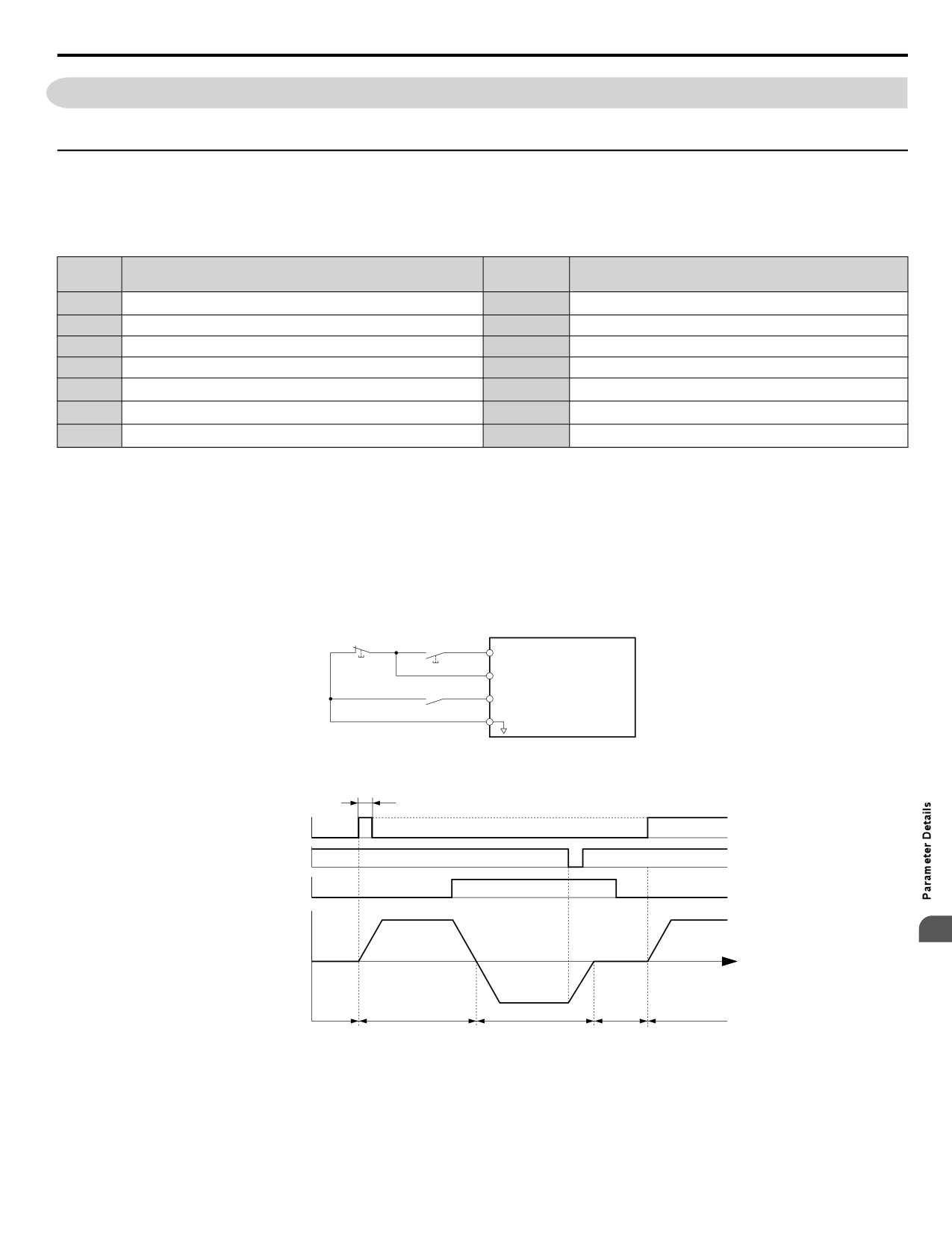
Setting 0: 3-Wire Sequence
The digital input programmed for 3-Wire control becomes the forward/reverse directional input, S1 becomes the Run command
input, and S2 becomes the Stop command input.
The drive starts the motor when the input S1 set for the Run command closes for longer than 2 ms. The drive stops the operation
when the Stop input S2 releases for 2 ms. When the digital input programmed for a forward/reverse operation is open, the
drive is set for forward operation. When the digital input is closed, the drive is set for reverse operation.
Note:
Input the Run and Stop commands via S1 and S2 when selecting a 3-Wire sequence.
Stop Switch
Run Switch
DRIVE
(N.C.)
(N.O.)
S1
Run Command (Runs when Closed)
S2
Stop Command (Stops when Open)
S5
FWD/REV (Multi-Function Input)
(H1-05 = 0)
SN
Standard Digital Input Common
Figure 5.39 3-Wire Sequence Wiring Diagram
2 ms min.
Can be either ON or OFF
Run command
Stop command
OFF (stopped)
Forward/reverse
OFF (forward)
ON (reverse)
command
5
Motor speed
TIME
Stop
Forward
Reverse
Stop
Foward
Figure 5.40 3-Wire Sequence
Note:
1.
The Run command must be closed for more than 2 ms.
2.
If the Run command is active at power up and b1-17 = 0 (Run command at power up not accepted), the Run LED will flash to indicate
that protective functions are operating. If required by the application, set b1-17 to 1 to automatically issue the Run command upon drive
power up.
163
5.7 H: Terminal Functions
WARNING! Sudden Movement Hazard. Ensure start/stop and safety circuits are wired properly and in the correct state before applying
power to the drive. Failure to comply could result in death or serious injury from moving equipment.
WARNING! Sudden Movement Hazard. The drive may start unexpectedly in reverse direction after power up if it is wired for 3-Wire sequence
but set up for 2-Wire sequence (default). Make sure b1-17 is set to “0” (drive does not accept a Run command active at power up). When
initializing the drive use 3-Wire initialization. Failure to comply could result in death or serious injury from moving equipment.
Setting 2: External Reference 1/2 Selection
Switches between two different sources of Run Commands and Frequency References. When multi-function digital input
selection 2 (Ext Ref Sel) is programmed, the Run Command and Frequency Reference source can be switched between External
Reference 1 (b1-01/b1-02) and External Reference 2 (b1-15/b1-16) if the drive is in AUTO mode.
Settings 3 to 5: Multi-Step Speed Reference 1 to 3
Switches multi-step speed frequency references d1-01 to d1-08 by digital inputs.
Setting 6: Jog Reference Selection
The Jog frequency set in parameter d1-17 becomes the frequency reference when the input terminal closes.
Setting 7: Accel/Decel Time Selection 1
Switches between accel/decel times 1 (C1-01 and C1-02) and 2 (C1-03 and C1-04). Refer to C1-01 to C1-04: Accel, Decel
Times 1 and 2 on page 140 for details.
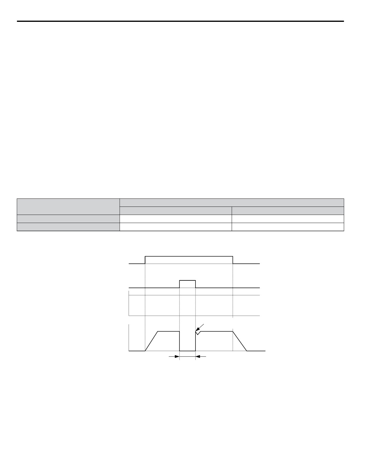
Settings 8 and 9: Baseblock Command (N.O., N.C.)
When the drive receives a baseblock command, the output transistors stop switching, the motor coasts to stop, and a bb alarm
flashes on the digital operator to indicate baseblock. When baseblock ends while a Run command is active, the drive performs
Speed Search to restart the motor.
Drive Operation
Digital Input Function
Input Open
Input Closed
Setting 8 (N.C.)
Baseblock (Interrupt output)
Normal operation
Setting 9 (N.O.)
Normal operation
Baseblock (Interrupt output)
WARNING! Sudden Movement Hazard. When using a mechanical holding brake with the drive in a lifting application, close the brake when
the drive output is cut off by a baseblock command triggered by one of the input terminals. Failure to comply will result in a slipping load
from the motor suddenly coasting when the baseblock command is entered and may cause serious injury or death.
OFF
ON
Run command
Baseblock
ON
release
Baseblock input
Frequency
reference
Begin Speed Search from the
previous frequency reference
Output frequency
Output off, motor coasts
Figure 5.41 Baseblock Operation During Run
Setting A: Accel/Decel Ramp Hold
When the digital input programmed for the Accel/decel ramp hold function closes, the drive locks (holds) the output frequency.
Acceleration or deceleration resumes when the input is reopened.
If the Accel/decel ramp hold function is enabled (d4-01 = 1), the drive saves the output frequency to memory when the Ramp
Hold input is closed. When the drive is restarted after stop or after power supply interruption, the saved output frequency
becomes the frequency reference (provided that the Accel/decel ramp hold input is still closed).
Setting B: Drive Overheat Alarm (oH2)
Triggers an oH2 alarm when the contact closes. Drive operation is not affected because this is an alarm.
164
5.7 H: Terminal Functions
Setting C: Analog Terminal Input Selection (Terminal A1, A2)
When closed, the terminals specified in H3-14 are enabled. When open, the drive disregards the input signal to the analog
terminals.
Setting F: Not Used/Through Mode
Select this setting when using the terminal in a pass-through mode. When set to F, an input does not trigger any function in
the drive. Setting F, however, still allows the input status of the terminal (open or closed) to be read out by a PLC via a
communication option or MEMOBUS/Modbus communications. The drive input terminals can then be used as remote I/O by
the PLC.
Settings 10 and 11: Up/Down Function
The Up/Down function allows the frequency reference to be set by two push buttons when one digital input is programmed
as the Up input (H1-oo= 10) to increase the frequency reference and the other digital input is programmed as the Down input
(H1-oo= 11) to decrease the frequency reference.
The Up/Down function takes priority over the frequency references from the digital operator, the analog inputs, and the pulse
input (b1-01 = 0, 1, 4). When using the Up/Down function, references provided by these sources will be disregarded.
The inputs operate as shown in Table 5.20:
Table 5.20 Up, Down Command
Status
Drive Operation
Up (10)
Down (11)
Open
Open
Hold current frequency reference
Closed
Open
Increase frequency reference
Open
Closed
Decrease frequency reference
Closed
Closed
Hold current frequency reference
Note:
1. An oPE03 alarm occurs when only one of the Up/Down functions is programmed to a digital input.
2. An oPE03 alarm occurs when the Up/Down function is assigned to the terminals and a different digital input is programmed for the
Accel/decel ramp hold function. For more information on alarms, Refer to Drive Faults, Alarms, Errors, and Messages on page
252.
3. The Up/Down function can only be used for External reference 1. Consider this when using Up/Down and the external reference switching
command (H1-oo = 2).
Using the Up/Down Function with Frequency Reference Hold (d4-01)
• If the frequency reference hold function is disabled (d4-01 = 0), the Up/Down frequency reference will be reset to 0 when
the Run command is cleared or the power is cycled.
• When d4-01 = 1, the drive will save the frequency reference set by the Up/Down function. When the Run command or the
power is cycled, the drive will restart with the saved reference value. Close the Up or Down input without an active Run
command to reset the saved value.
Using the Up/Down Function with Frequency Reference Limits
Parameter d2-01 determines the upper frequency reference limit.
The value for the lower frequency reference limit depends on the parameter d4-10 setting. This value can be set by an analog
input or parameter d2-02. When a Run command is applied, the lower limits function as follows:
• If the lower limit is set by d2-02 only, the drive accelerates to this limit as soon as a Run command is entered.
• If the lower limit is determined by an analog input only, the drive accelerates to the limit when both the Run command and
an Up or Down command are active. The drive will not start running if only the Run command is active.
• If the lower limit is set by both an analog input and d2-02, and the analog limit is higher than the d2-02 value, the drive
5
accelerates to the d2-02 value when a Run command is input. When the d2-02 value is reached, the drive accelerates to the
analog limit only if an Up or Down command is set.
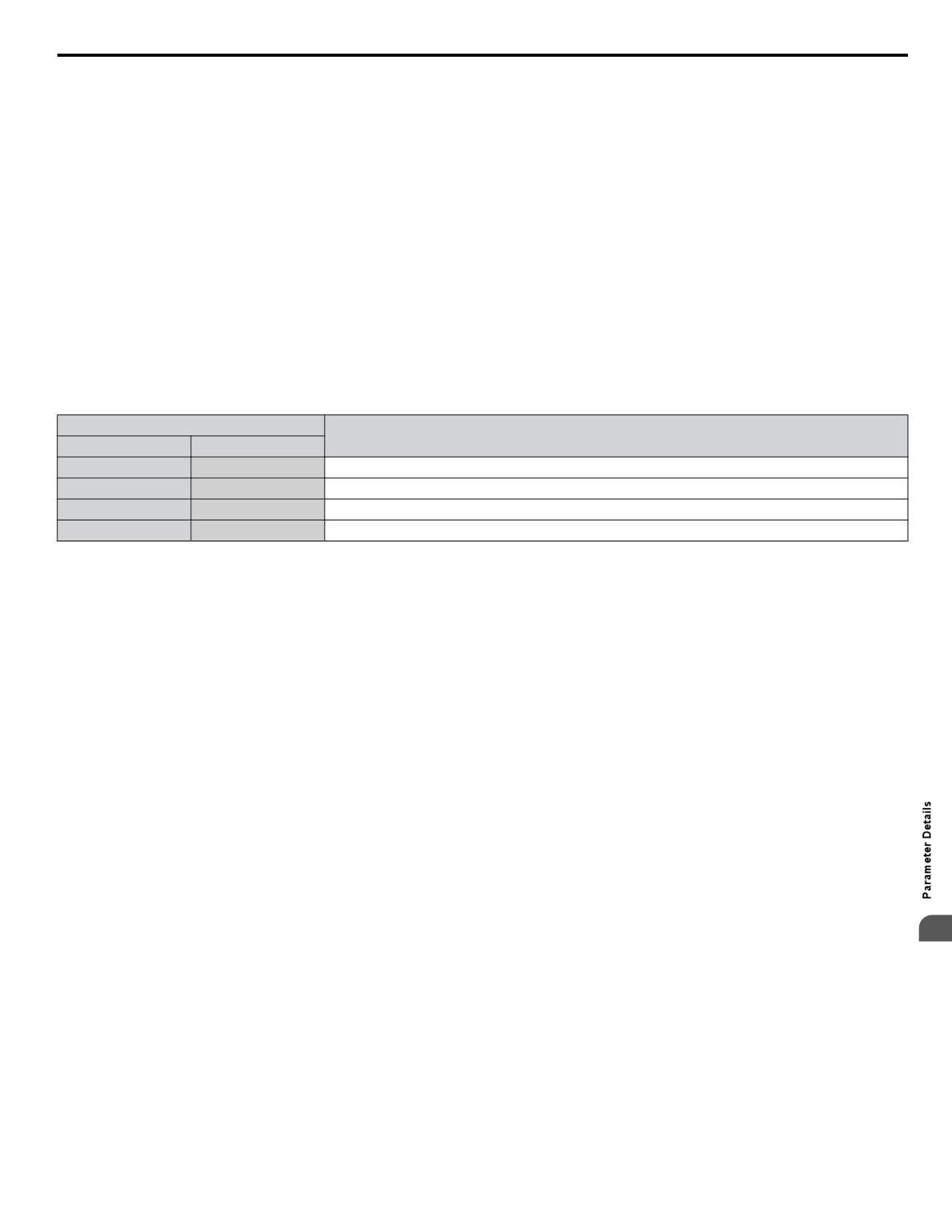
Figure 5.42 shows an Up/Down function example with a lower frequency reference limit set by d2-02, and the frequency
reference hold function both enabled and disabled.
165
5.7 H: Terminal Functions
Output frequency
upper limit
Accelerates to
lower limit
d4-01 = 1
Same
frequency
d4-01 = 0
Lower limit
FWD run/stop
ON
ON
Up command
Hold
ON
frequency
reset
Down command
ON
ON
Power supply
Figure 5.42 Up/Down Command Operation
Settings 12 and 13: Forward Jog, Reverse Jog
Digital inputs programmed as Forward Jog (H1-oo = 12) and Reverse Jog (H1-oo = 13) are Jog inputs that do not require
a Run command. Closing the terminal set for Forward Jog input will cause the drive to ramp to the Jog frequency reference
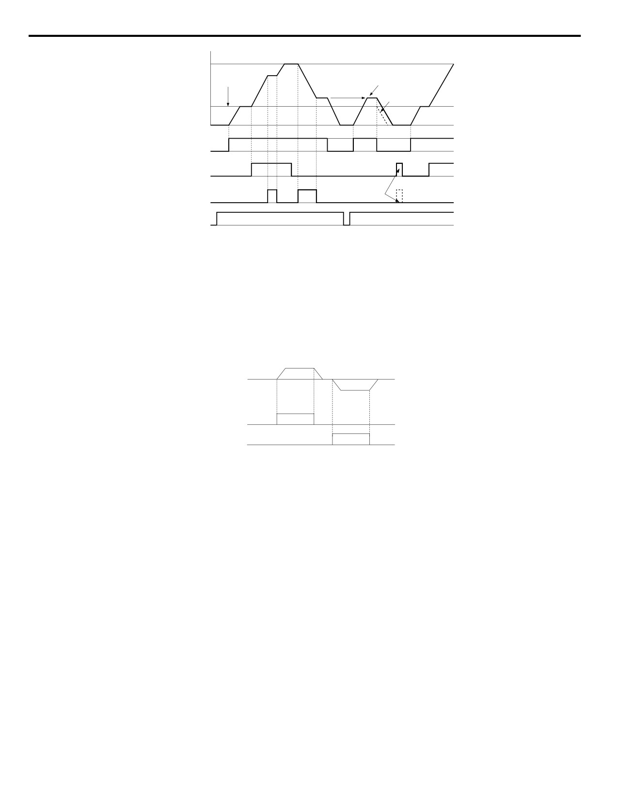
(d1-17) in the forward direction. The Reverse Jog will cause the same action in the reverse direction. The Forward Jog and
Reverse Jog command can be set independently.
Note:
The Forward Jog and Reverse Jog commands override all other frequency references. However, if the drive is set to prohibit reverse rotation
(b1-04 = 1), activating Reverse Jog will have no effect. Inputting both the Forward Jog and Reverse Jog are simultaneously for 500 ms or
longer will trigger an alarm will and the drive will ramp to stop.
d1-17
Output
Frequency
d1-17
ON
FJOG
ON
RJOG
Figure 5.43 FJOG/RJOG Operation
Setting 14: Fault Reset
When the drive detects a fault condition, the fault output contact closes, the drive output shuts off, and the motor coasts to
stop (specific stopping methods can be selected for some faults such as L1-04 for motor overheat). After removing the Run
command, clear the fault either by pressing the RESET key on the digital operator or closing a digital input configured as a
Fault Reset (H1-oo = 14).
Note:
Remove the Run command prior to resetting a fault. Fault Reset commands are ignored while the Run command is present.
Settings 15 and 17: Fast Stop (N.O., N.C.)
The Fast Stop function operates similar to an emergency stop input to the drive. If a Fast Stop command is input while the
drive is running, the drive decelerates to a stop in the deceleration time set to C1-09. The drive can only be restarted after
bringing the drive to a complete stop, turning off the Fast Stop input, and switching off the Run command.
• To trigger the Fast Stop function with an N.O. switch, set H1-oo = 15.
• To trigger the Fast Stop function with an N.C. switch, set H1-oo = 17.
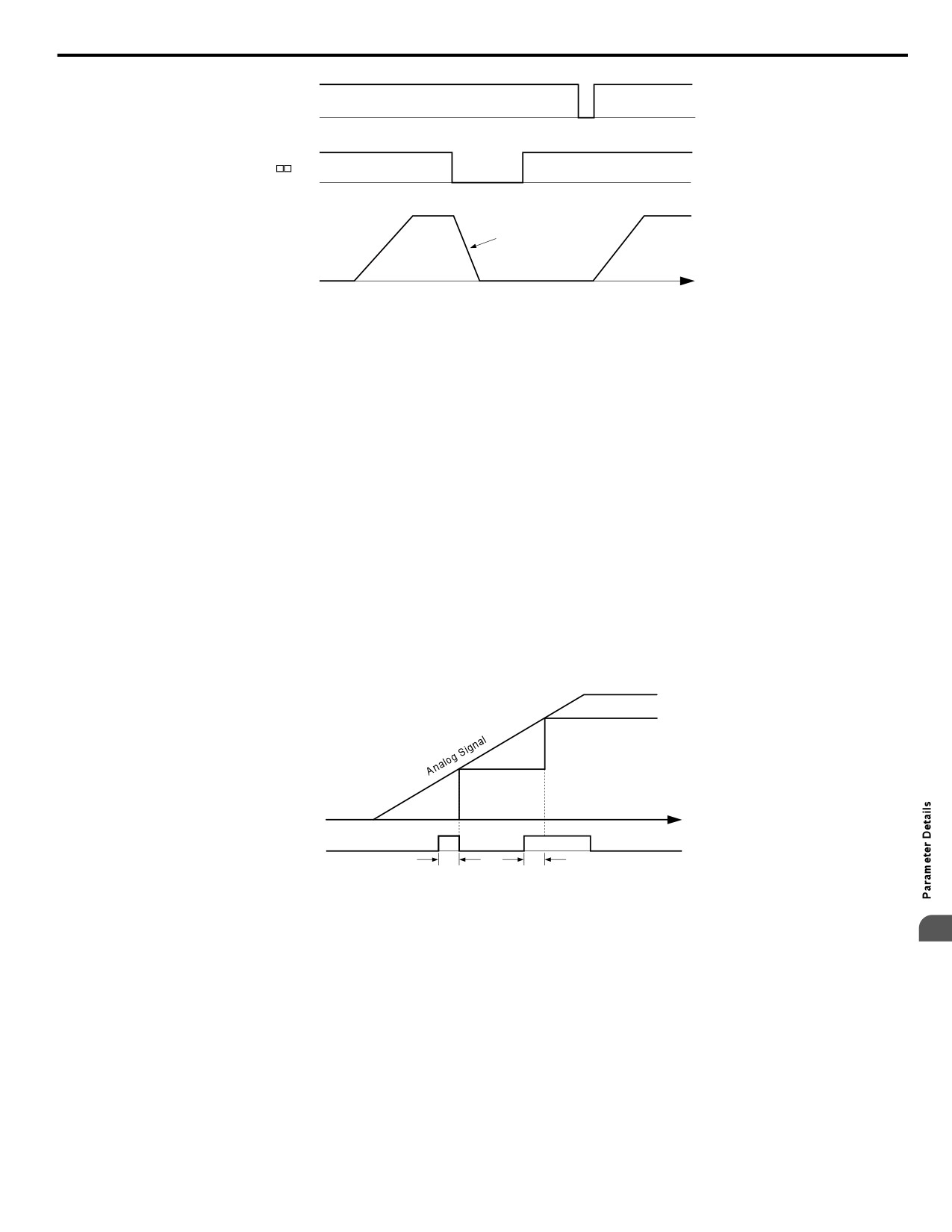
Figure 5.44 shows an operation example of Fast Stop.
166
5.7 H: Terminal Functions
Run/Stop
ON
ON
Fast-Stop
H1-
= 17
ON
ON
Decelerates at C1-09
Output Frequency
TIME
Figure 5.44 Fast Stop Sequence
NOTICE: Rapid deceleration can trigger an overvoltage fault. When faulted, the drive output shuts off, and the motor coasts. To avoid this
uncontrolled motor state and to ensure that the motor stops quickly and safely, set an appropriate Fast Stop time to C1-09.
Setting 18: Timer Function Input
This setting configures a digital input terminal as the input for the timer function. Use this setting combination with the timer
function output (H2-oo = 12).
Setting 19: PID Disable
Close a digital input to indefinitely disable the PID function. When the input is released, the drive resumes PID operation.
Setting 1B: Program Lockout
Parameter values cannot be changed when an input is programmed for Program Lockout and the input is open. It is still possible,
however, to view and monitor parameter settings.
Setting 1E: Reference Sample Hold
This function allows the user to sample an analog frequency reference signal being input to terminal A1, A2, or A3 and hold
the frequency reference at the sampled level. When the Analog Frequency Reference Sample/Hold function is held for at least
100 ms, the drive reads the analog input and changes the frequency reference to the newly sampled speed as illustrated in
Figure 5.45.
When the power is shut off and the sampled analog frequency reference is cleared, the frequency reference is reset to 0.
Frequency
Reference
Time
Reference
OFF
ON
Sample Hold Input
100 ms
100 ms
Figure 5.45 Analog Frequency Reference Sample/Hold
5
An oPE03 error will occur when one of the following functions is used simultaneously with the Analog frequency reference
sample/hold command:
• Hold accel/decel stop (setting: A)
• Up command, Down command (setting: 10, 11)
• Up or Down functions (setting: 75, 76)
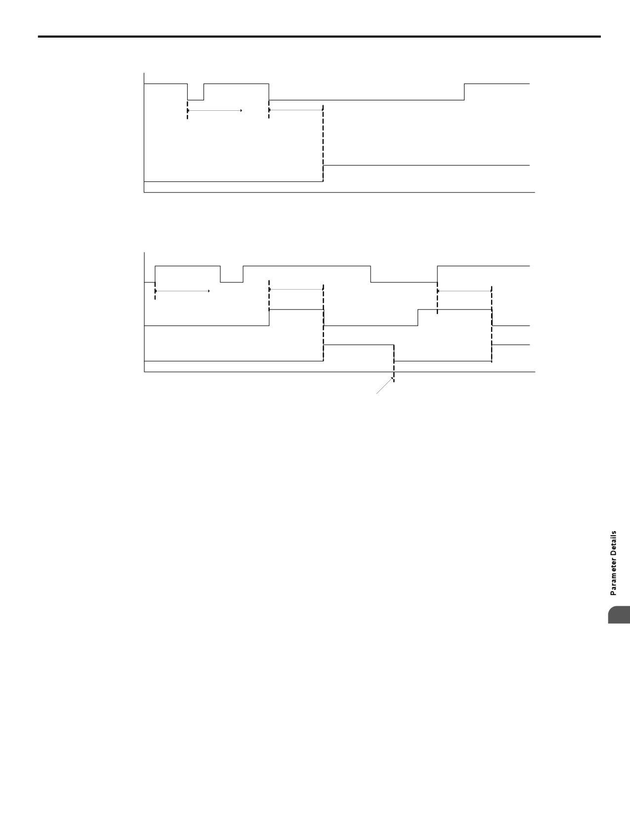
Settings 20 to 2F: External Fault
The External fault command stops the drive when problems occur with external devices.
To use the External fault command, set one of the multi-function digital inputs to a value between 20 and 2F. The digital
operator will display EFo where o is the number of the terminal to which the external fault signal is assigned.
For example, if an external fault signal is input to terminal S3, “EF3” will be displayed.
167
5.7 H: Terminal Functions
Select the value to be set in H1-oo from a combination of any of the following three conditions:
• Signal input level from peripheral devices (N.O., N.C.)
• External fault detection method
• Operation after external fault detection
An “On-Delay” timer will be applied to the external fault if it is “Normally Open” and an “Off-Delay” timer will be applied
to the external fault if it is “Normally Closed”.
If the external fault is set to “During Run”, the time delay will start after the Run command is received.
Refer to Figure 5.46 to Figure 5.48 for details.
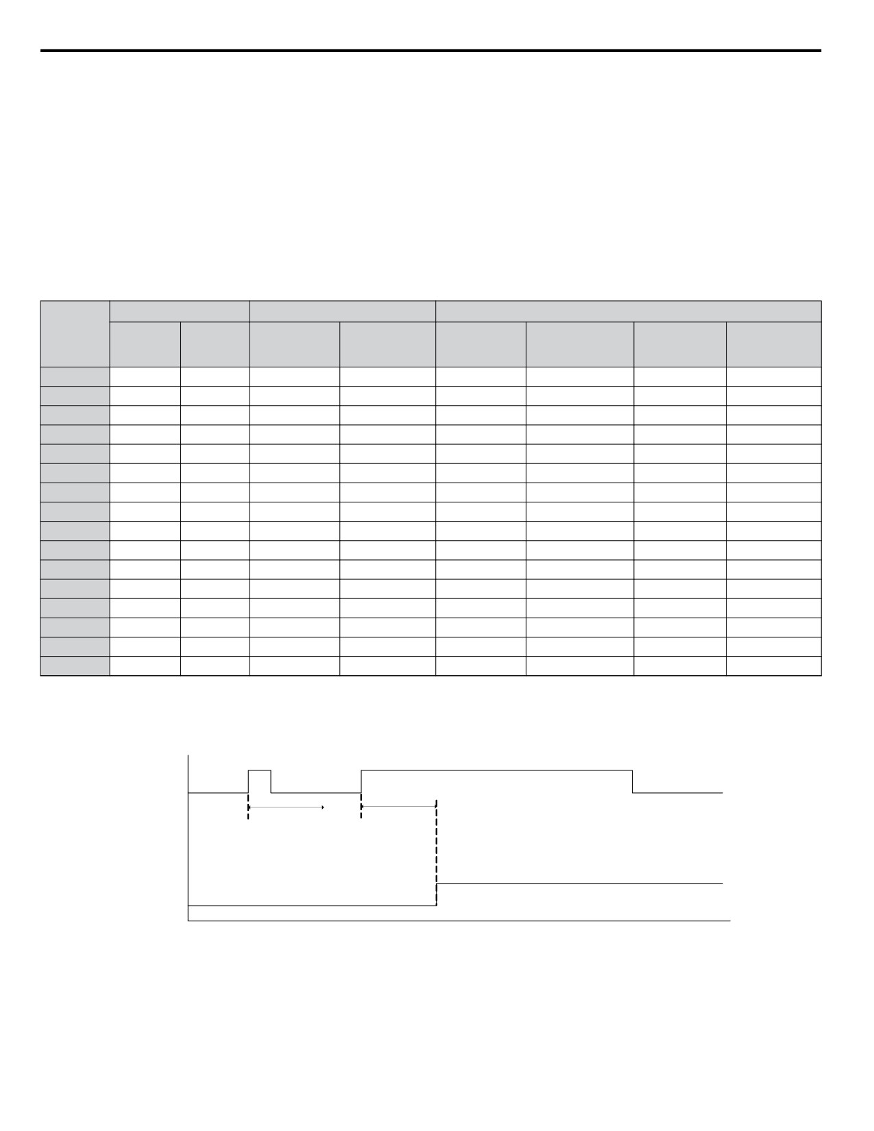
Table 5.21 shows the relationship between the conditions and the value set to H1-oo:
Terminal statuses, detection conditions, and stopping methods marked with an “O” are applicable to the corresponding settings.
Table 5.21 Stopping Method for External Fault
Terminal Status <1>
Detection Conditions <2>
Stopping Method
Setting
Detected
Alarm Only
Always
Ramp to Stop
Coast to Stop
Fast Stop
N.O.
N.C.
during Run
(continue
Detected
(fault)
(fault)
(fault)
only
running)
20
O
O
O
21
O
O
O
22
O
O
O
23
O
O
O
24
O
O
O
25
O
O
O
26
O
O
O
27
O
O
O
28
O
O
O
29
O
O
O
2A
O
O
O
2B
O
O
O
2C
O
O
O
2D
O
O
O
2E
O
O
O
2F
O
O
O
<1>
Determine the terminal status for each fault, i.e., whether the terminal is normally open or normally closed.
<2>
Determine whether detection for each fault should be enabled only during run or always detected.
External Pump Fault (or Alarm) N.O. Always Detected
Closed
Pump Fault
Digital Input
Open
(H1-0☐ = 2☐)
H1-2☐
H1-2☐
EF☐ Delay Time
EF☐ Delay
Time
EF☐ Pump
Fault or Alarm
Figure 5.46 External Pump Fault and Alarm N.O. Always Detected
168
5.7 H: Terminal Functions
External Pump Fault (or Alarm) N.C. Always Detected
Closed
Pump Fault
Digital Input
Open
(H1-0☐ = 2☐)
H1-2☐
H1-2☐
EF☐ Delay Time
EF☐ Delay
Time
EF☐ Pump
Fault or Alarm
Figure 5.47 External Pump Fault and Alarm N.C. Always Detected
External Pump Fault N.O. Detected During Run
Closed
Pump Fault
Digital Input
Open
(H1-0☐ = 2☐)
H1-2☐
H1-2☐
H1-2☐
EF☐ Delay Time
EF☐ Delay
EF☐ Delay
Time
Time
Drive
Running
or Sleeping
EF☐ Pump
Fault
Fault Reset
Commanded
Figure 5.48 External Pump Fault N.O. Detected During Run
Setting 30: PID Integral Reset
Configuring one of the digital inputs for PID integral reset (H1-oo = 30) resets the value of the integral component in PID
control to 0 when the terminal is closed.
Setting 31: PID Integral Hold
Configuring a digital input for Integral Hold (H1-0o = 31) locks the value of the integral component of the PID control as
long as the input is active. The PID controller resumes integral operation from the hold value as soon as the integral hold input
is released.
Setting 32: Multi-Step Speed Reference 4
Selects the multi-step speeds d1-09 to d1-16 in combination with the input terminal set for Multi-Step Speed 1, 2 and 3.
Setting 34: PID Soft Starter Cancel
A digital input configured as a PID soft starter cancel input (H1-0o = 34) enables or disables the PID soft starter and cancels
the PID accel/decel time (b5-17).
5
Setting 35: PID Input Level Selection
Allows an input terminal to switch the sign of the PID input.
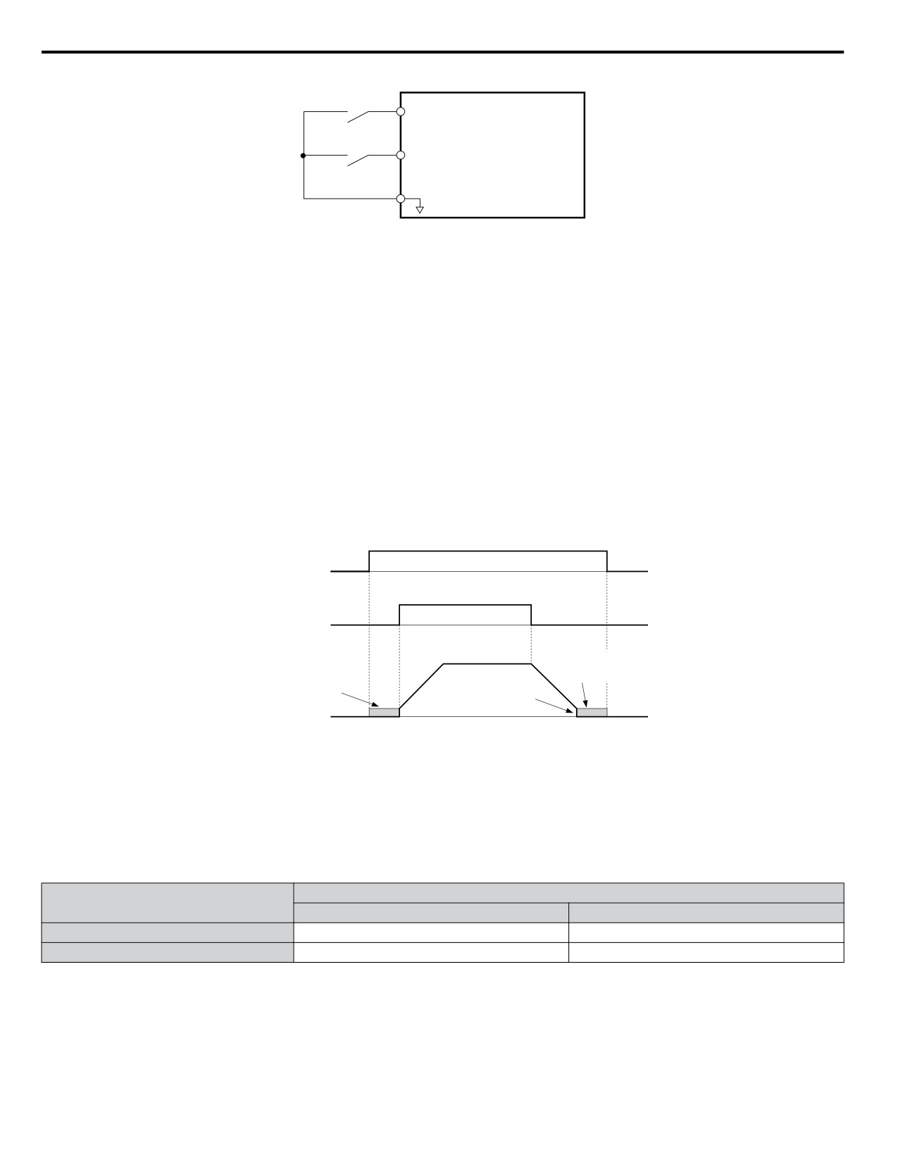
Settings 40 and 41: Forward Run, Reverse Run Command for 2-Wire Sequence
Configures the drive for a 2-Wire sequence.
When an input terminal set to 40 closes, the drive operates in the forward direction. When an input set for 41 closes, the drive
operates in reverse. Closing both inputs simultaneously will result in an external fault.
Note:
1. This function cannot be used simultaneously with settings 42 and 43.
2. The same functions are assigned to terminals S1 and S2 when the drive is initialized for 2-Wire sequence.
169
5.7 H: Terminal Functions
Drive
Forward Run
S1
Reverse Run
S2
Standard Digital
SN
Input Common
Figure 5.49 Example Wiring Diagram for 2-Wire Sequence
Settings 42 and 43: Run and Direction Command for 2-Wire Sequence 2
Sets the drive for 2-Wire sequence 2.
When an input terminal programmed for 42 closes, the drive will operate in the selected direction. The drive will stop when
the input opens.
The input programmed for 43 selects the direction. If the input is open, forward direction is selected. If the input is closed,
reverse direction is selected.
Note:
This function cannot be used simultaneously with settings 40 and 41.
Setting 47: Node Setup
If the SI-S3 option card is connected, closing this terminal sets a node address for operation on a CANopen network.
Setting 60: DC Injection Braking Command
DC Injection Braking is activated when a DC Injection Braking command is input while the drive is stopped. DC Injection
Braking is released when a Run command or a Jog command is input.
The diagram below illustrates DC Injection Braking:
DC Injection braking
OFF
ON
OFF
command
OFF
ON
OFF
FWD Run command
DC Injection
DC Injection
braking
braking
DC Injection Braking
Start Frequency
(b2-01)
Output frequency
Figure 5.50 DC Injection Braking Input Timing Diagram
Settings 61 and 62: External Speed Search Command 1, 2
These input functions enable Speed Search even if parameter b3-01 = 0 (no Speed Search at start).
Note:
Assigning Speed Search 1 and Speed Search 2 to input terminals will trigger an oPE03 error.
Settings 65 and 66: KEB Ride-Thru 1 (N.C.), 2 (N.O.)
Enables the KEB Ride-Thru function selected in parameter L2-29.
Drive Operation
Digital Input Function
Input Open
Input Closed
Setting 65 (N.C.)
KEB Ride-Thru Deceleration
Normal operation
Setting 66 (N.O.)
Normal operation
KEB Ride-Thru Deceleration
Note:
Simultaneously assigning KEB Ride-Thru 1 and KEB Ride-Thru 2 to the input terminals will trigger an oPE03 error.
Setting 67: Communication Test Mode
The drive has a built-in function to self-diagnose serial communications operation. The test involves wiring the send and
receive terminals of the RS-422/RS-485 port together. The drive transmits data and then confirms that the communications
are received normally.
170
5.7 H: Terminal Functions
Setting 6A: Drive Enable
A digital input configured as a “Drive enable” (H1-oo = 6A) will prevent the drive from executing a Run command until
the input is closed. When the input is open, the digital operator will display “dnE” to indicate that the drive is disabled.
If a Run command is enabled before the terminal set for “Drive enable” closes, then the drive will not run until the Run
command is cycled (i.e., a new Run command is required). If the input is opened while the drive is running, the drive will stop
according to the stop method set to b1-03. Refer to b1-03: Stopping Method Selection on page 118 for details.
Setting 73: Low City Press
Indicates that sufficient or insufficient pressure is present on the inlet to the pump. Used mainly for pressure booster situations.
Settings 75 and 76: Up 2/Down 2 Function
The Up/Down 2 function adds a bias to the frequency reference. The input programmed for 75 will increase the bias and the
input programmed for 76 will decrease the bias. Table 5.22 explains how the Up/Down 2 function works depending on the
frequency reference source and parameters d4-01, d5-03, and d4-05.
Note:
1. The Up/Down 2 functions must be set as a pair.
2. When using the Up/Down 2 function, set appropriate bias limit values to parameters d4-08 and d4-09.
Table 5.22 Up/Down 2 Operations
Freq. Ref.
Condition
d4-03
d4-05
d4-01
Operation
Frequency Saved
Source
1
0
•
Accelerates (increases the bias) while the Up 2
Not saved
terminal is closed.
•
Decelerates (decreases the bias) while Down 2 is
closed.
If the bias and frequency reference
0
•
Holds output frequency (holds the bias) when no
are constant for 5 s, the bias is
2
1
Up 2 or Down 2 input or both active.
added to the active frequency
•
Resets the bias when the reference changes.
reference and reset afterwards.
Multi-Step Speed
0
Reference
•
Operates with the frequency reference in all other
situations.
•
Accelerates (increases the bias) while the Up 2
terminal is closed.
3
1
--
•
Decelerates (decreases the bias) while Down 2 is
Not saved
closed.
•
Otherwise operates at the frequency reference.
4
0
•
When the Up 2 is enabled, the drive accelerates to
Not saved
the frequency reference plus d4-03 (bias is
increased for d4-03).
•
When Down 2 is enabled, the drive decelerates to
the frequency reference minus d4-03 (bias is
Value
decreased for d4-03).
If the bias and frequency reference
Multi-Step Speed
other
--
are constant for 5 s, the bias is
Reference
•
Holds output frequency (holds the bias) when
5
than 0
1
neither Up/Down 2 inputs are active or both inputs
added to the active frequency
are active.
reference and reset afterwards.
•
Resets the bias when the reference changes.
•
Operates with the frequency reference in all other
situations.
6
0
•
Accelerates (increases the bias) while the Up 2
Not saved
terminal is closed.
•
Decelerates (decreases the bias) while Down 2 is
closed.
If the bias is constant for 5 s, it is
5
•
Holds output frequency (holds the bias) when
Other (analog
saved to parameter d4-06. The
0
0
neither Up/Down 2 inputs are active or both inputs
7
comm., etc.)
1
frequency reference cannot be
are active.
overwritten, so only the bias is
•
If the frequency reference changes for more than
saved.
the time set to d4-07 during accel/decel, bias value
is held until the output frequency meets the
reference (speed agree).
171
5.7 H: Terminal Functions
Freq. Ref.
Condition
d4-03
d4-05
d4-01
Operation
Frequency Saved
Source
• Accelerates (increases the bias) while the Up 2
terminal is closed.
8
0
1
--
• Decelerates (decreases the bias) while Down 2 is
Not saved
closed.
• Otherwise operates at the frequency reference
9
0
• When Up 2 is enabled, drive accelerates to the
Not saved
Other (analog
frequency reference plus d4-03 (increases the bias
comm, etc.)
for d4-03).
Value
• When Down 2 is enabled, drive decelerates to the
If the bias is constant for 5 s, it is
other
--
frequency reference minus d4-03 (decreases the
saved to parameter d4-06. The
10
than 0
1
bias for d4-03).
frequency reference cannot be
overwritten, so only the bias is
• If the frequency reference changes for more than
saved.
d4-07 during accel/decel, bias value is held until the
output frequency meets the reference (speed agree).
Settings 7A and 7B: KEB Ride-Thru 2 (N.C., N.O.)
An input terminal set to 7A or 7B can trigger Single Drive KEB Ride-Thru during deceleration. L2-29 is disregarded if this
is enabled.
Drive Operation
Digital Input Function
Input Open
Input Closed
Setting 7A (N.C.)
Single Drive KEB Ride-Thru 2
Normal operation
Setting 7B (N.O.)
Normal operation
Single Drive KEB Ride-Thru 2
Note:
Simultaneously assigning KEB Ride-Thru 1 and KEB Ride-Thru 2 to the input terminals will trigger an oPE03 error.
Setting 80: HAND Mode
Closing this input will put the drive in HAND Mode.
If this contact is closed within one second of power-up, the drive will honor the utility delay time.
Note:
When inputs 80 and 81 are closed simultaneously, input 80 has priority and P5-01 determines the frequency reference.
Setting 81: HAND Mode 2
Closing this input will put the drive in HAND Mode using P5-05 as a frequency reference.
If this contact is closed within one second of power-up, the drive will honor the utility delay time.
Note:
When inputs 80 and 81 are closed simultaneously, input 80 has priority and P5-01 determines the frequency reference.
Settings 83, 84, and 85: Alternate Multi-step Setpoints
These setpoint selections are different from Multi Setpoints 1 and 2 (H1-oo = 8D/8E) in that each input is dedicated to a
setpoint instead of being a binary selection.
Table 5.23 shows active setpoints based on the Alternate Multi-Setpoint Selections (H1-oo = 83 to 85):
Table 5.23 Active Setpoints by H1-oo Setting
Alternate Multi-Setpoint Q1-02
Alternate Multi-Setpoint Q1-03
Alternate Multi-Setpoint Q1-04
Setpoint
H1-oo = 83
H1-oo = 84
H1-oo = 85
Open
Open
Open
Q1-01
Closed
Open/Closed
Open/Closed
Q1-02
Open
Closed
Open/Closed
Q1-03
Open
Open
Closed
Q1-04
Setting 88: Volute-Thermostat (N.O.)
Closed: Drive will trip on “VLTS - Volute-TStat Flt”.
Open: Thermostat fault not active.
Note:
Assigning both 88 and 89 to input terminals will trigger a VLTS-Volute-TStat Flt.
Setting 89: Volute-Thermostat (N.C.)
Closed: Thermostat fault not active.
Open: Drive will trip on “VLTS - Volute-TStat Flt”.
Note:
Assigning both 88 and 89 to input terminals will trigger a VLTS-Volute-TStat Flt.
172
5.7 H: Terminal Functions
Setting 8C: Disable Pre-Charge
Close to disable pre-charge.
Settings 8D and 8E: Multi Setpoints 1 and 2
Settings 8D and 8E will override all other PID setpoints when closed.
Table 5.24 Multi Setpoints 1 and 2
Multi Setpoint 1
Multi Setpoint 2
Setpoint Source
(H1-0o = 8D)
(H1-0o = 8E)
Frequency Ref (dependent on b1-01), Setpoint 1 - Q1-01 (when b1-01 = 0),
Open
Open
Analog Setpoint (H3-0o = C), Pulse Input Setpoint (H6-01 = 2), or
MEMOBUS setpoint.
Closed
Open
Setpoint 2 - Q1-02
Open
Closed
Setpoint 3 - Q1-03
Closed
Closed
Setpoint 4 - Q1-04
Setting 8F: Low Water Level
Function is active in AUTO Mode during normal operation and is also used with Pre-charge function.
Function depends on P1-30, Low Water Digital Input Configuration, setting.
When P1-30 = 0 (N.O.): Closed: Low Water Level Fault. Open: Reservoir/Tank is filled to normal level.
When P1-30 = 1 (N.C.): Closed: Reservoir/Tank is filled to normal level. Open: Low Water Level Fault.
Pre-charge function uses low water level input as “Tank/Reservoir” feedback to indicate water level reached.
Setting 90: High Water Level
Function is active when the drive is running and depends on P1-31, High Water Digital Input Configuration, setting.
When P1-31 = 0 (N.O.): Closed: High Water Level Fault. Open: Reservoir/Tank is filled to normal level.
When P1-30 = 1 (N.C.): Closed: Reservoir/Tank is filled to normal level. Open: High Water Level Fault.
Setting 95: Remove Drive Disable
Prevents the drive from running when active for the time set in P4-26. Must be inactive for the time set in P4-27 to allow the
drive to run again.
Note:
Parameter P4-25 determines whether this input is Normally Open or Normally Closed.
Setting B0: Emergency Override Function
The Emergency Override function is activated by closing the digital input programmed for Emergency Override Forward Run
(H1-oo = AF) or Emergency Override Reverse Run (H1-oo = B0).
If H1-oo = 6A (Drive Enable) is programmed, it must be opened to disable the drive for Emergency Override to take effect.
Closing both Emergency Override digital inputs at the same time will trigger an External Fault (EF) error.
When the drive is in Emergency Override, the frequency reference source is dependent on parameter S6-02, Emergency
Override Reference Selection. When S6-02 is set to 0 (Use S6-01 Reference), the drive will run at the S6-01 setting. When
S6-02 is set to 1 (Use Frequency Ref), the drive will use the currently selected frequency reference (based on b1-01 and HAND/
AUTO) as the run speed.
An alarm will flash during Emergency Override indicating that the function is active and the direction the drive is commanded
to run.
Resettable faults occurring when Emergency Override is activated will be cleared.
5
The drive will perform unlimited speed search retries during Emergency Override.
When Emergency Stop is active and Emergency Override is activated, the drive will run in Emergency Override mode.
The CALL (Serial Communication Error) mechanism is deactivated when Emergency Override is activated.
The Emergency Override function has priority over the PID Sleep feature (b5-15/b5-16).
Setting AF: Emergency Override Forward Run
Enables Emergency Override Forward Run (Enabled when S6-01 = 1).
Setting B0: Emergency Override Reverse Run
Enables Emergency Override Reverse Run (Enabled when S6-01 = 1).
173
5.7 H: Terminal Functions
u H2: Multi-Function Output
n H2-01 to H2-03: Terminal MA/MB/MC, P1/PC, and P2/PC Function Selection
The drive has three multi-function output terminals.
No.
Parameter Name
Setting Range
Default
H2-01
Terminal MA, MB and MC Function Selection (relay)
0 to 1AA
E: Fault
H2-02
Terminal P1 Function Selection (open-collector)
0 to 1AA
37: During Frequency Output
H2-03
Terminal P2 Function Selection (open-collector)
0 to 1AA
E: Fault
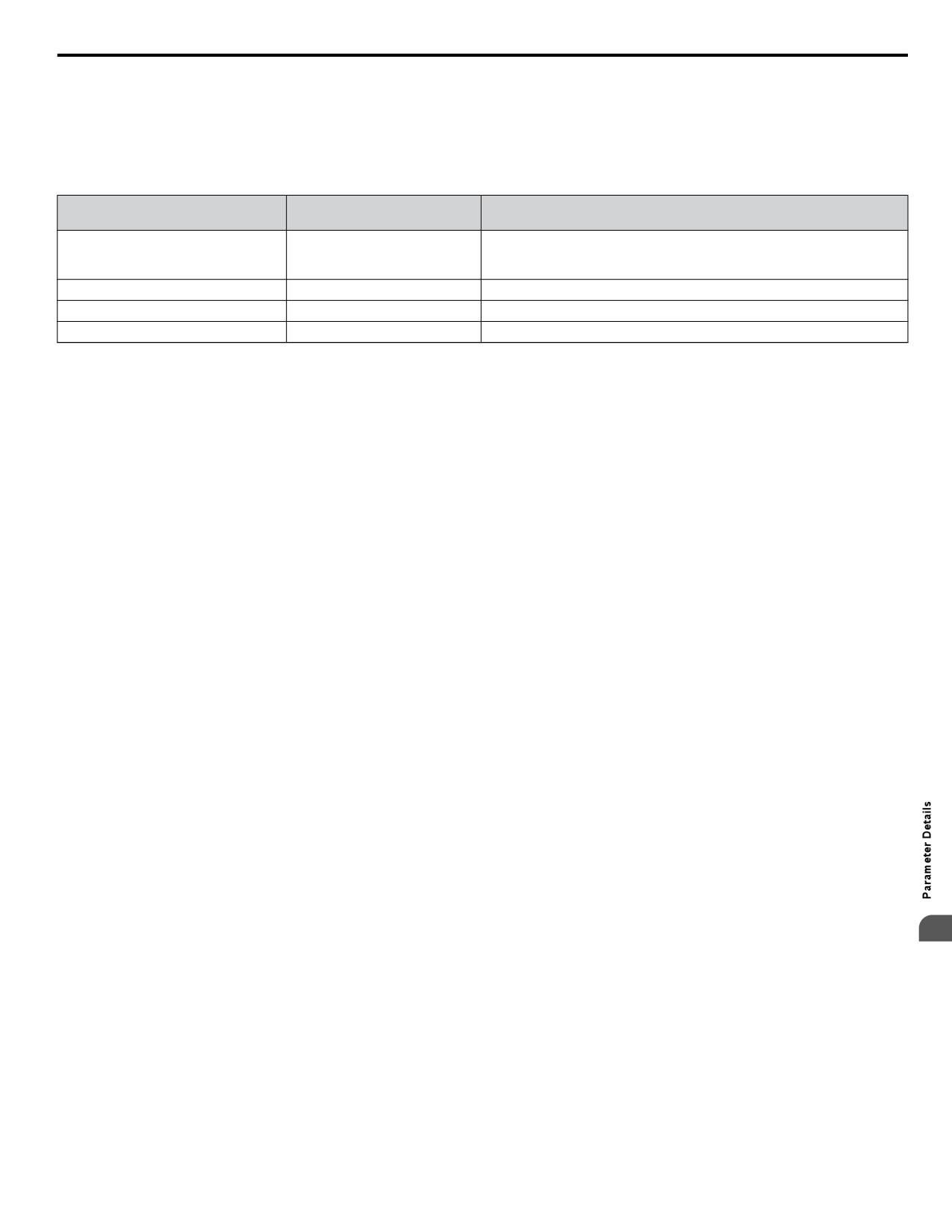
Setting 0: During Run
Output closes when the drive is outputting a voltage.
Status
Description
Open
Drive is stopped.
Closed
A Run command is input or the drive is in deceleration or DC injection.
OFF
ON
Run command
Baseblock
OFF
ON
command
Output
frequency
During Run
OFF
ON
Figure 5.51 During Run Time Chart
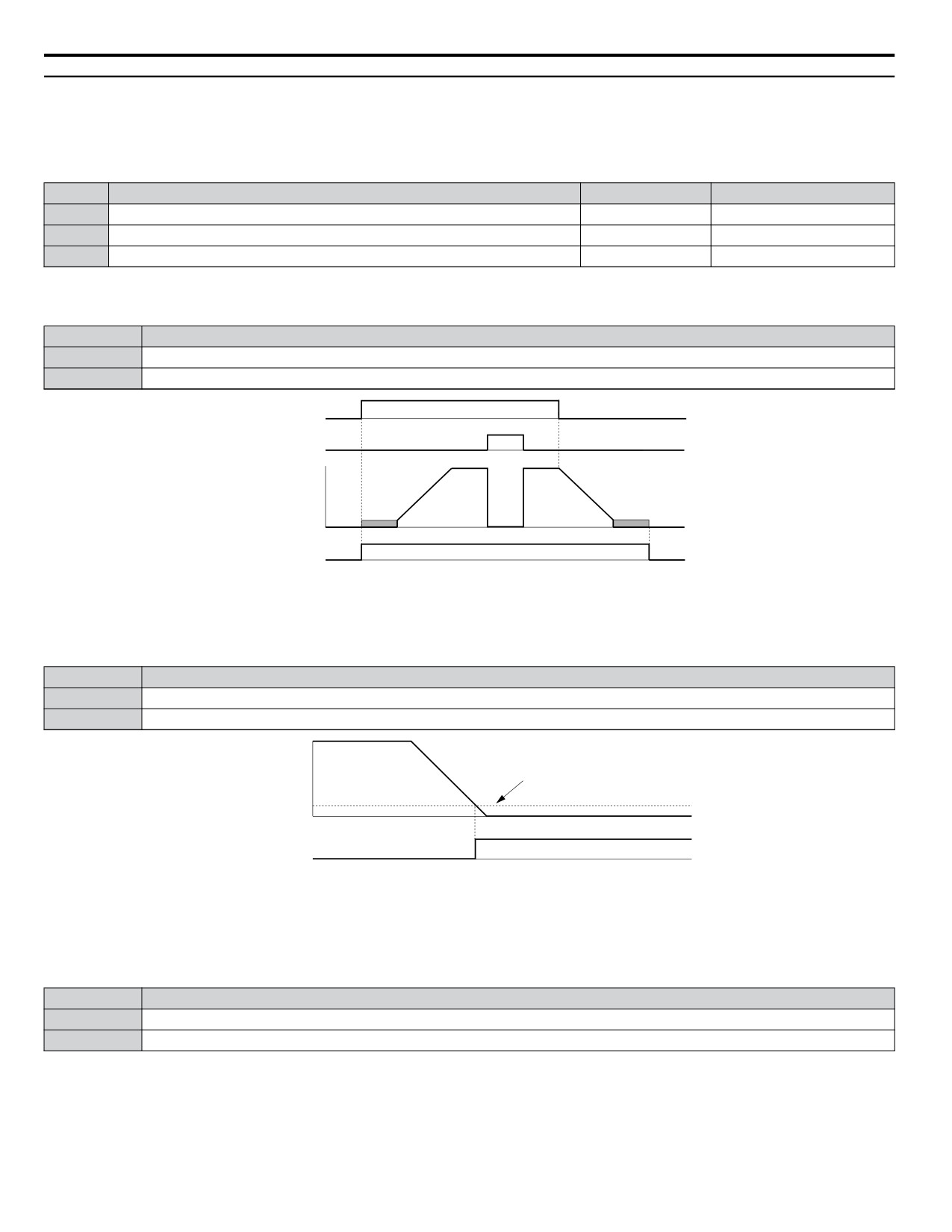
Setting 1: Zero Speed
Terminal closes when the output frequency falls below the minimum output frequency set to E1-09 or b2-01.
Status
Description
Open
Output frequency is above the minimum output frequency set to E1-09 or b2-01
Closed
Output frequency is less than the minimum output frequency set to E1-09 or b2-01
Output frequency
or
E1-09 (Max. Output Frequency) or
motor speed
b2-01 (Zero Speed Level)
OFF
ON
Zero Speed
Figure 5.52 Zero-Speed Time Chart
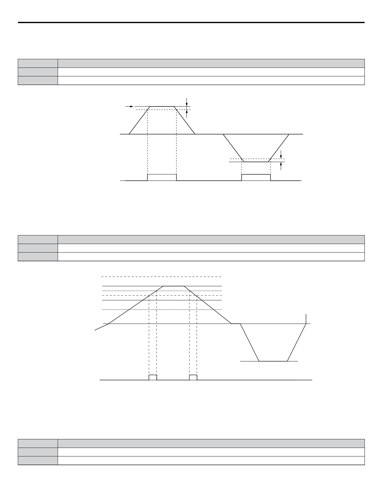
Setting 2: Speed Agree 1 (fref/fout Agree 1)
Closes when the actual output frequency is within the Speed Agree Width (L4-02) of the current frequency reference regardless
of the direction.
Status
Description
Open
Output frequency or motor speed does not match the frequency reference while the drive is running.
Closed
Output frequency or motor speed is within the range of frequency reference ±L4-02.
Note:
Detection works in forward and reverse.
174
5.7 H: Terminal Functions
Frequency
reference
Output Frequency
L4-02
or Motor Speed
L4-02
Speed agree 1
OFF
ON
Figure 5.53 Speed Agree 1 Time Chart
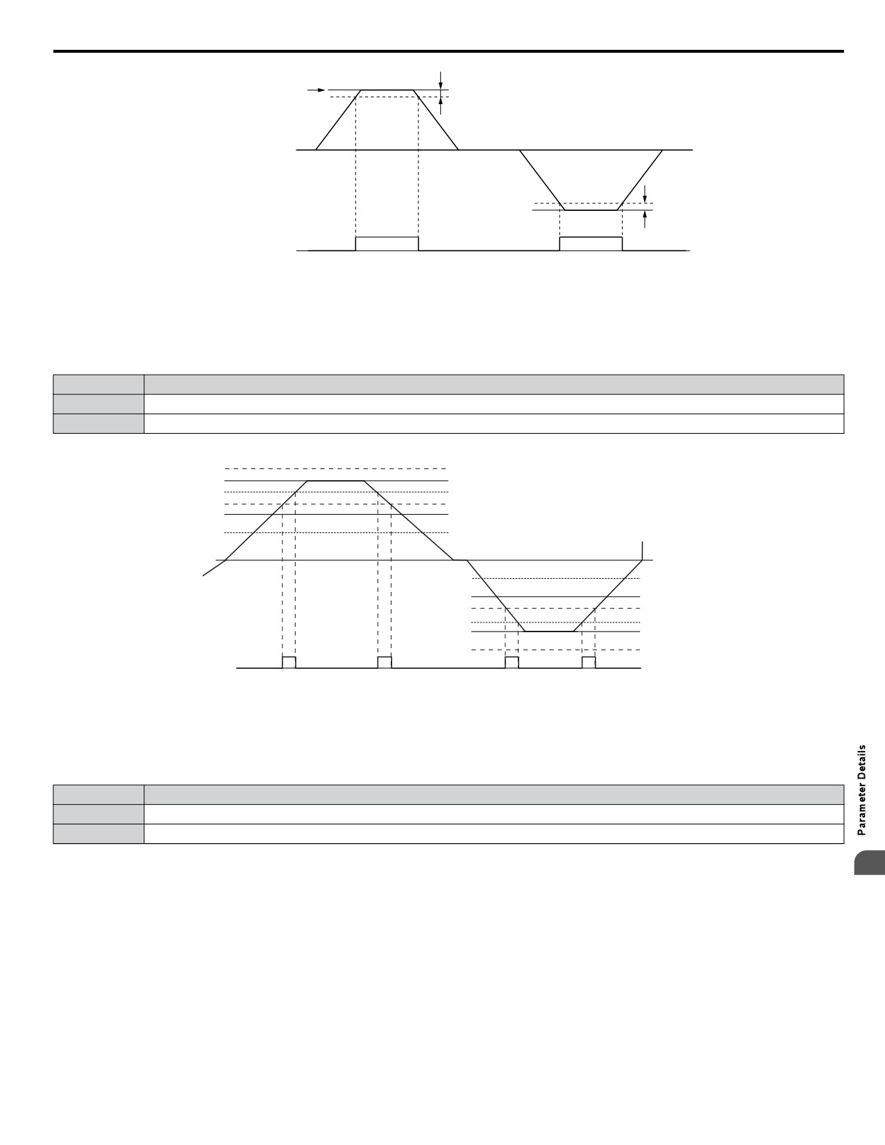
Setting 3: User-Set Speed Agree 1 (fref/fset Agree 1)
Closes when the actual output frequency and the frequency reference are within the speed agree width (L4-02) of the
programmed speed agree level (L4-01).
Status
Description
Open
Output frequency or motor speed and frequency reference are not both within the range of L4-01 ±L4-02.
Closed
Output frequency or motor speed and the frequency reference are both within the range of L4-01 ±L4-02.
Note:
Frequency detection works in forward and reverse. The value of L4-01 is used as the detection level for both directions.
Frequency reference + L4-02
Frequency reference
L4-01 + L4-02
Frequency reference - L4-02
L4-01
L4-01 - L4-02
Output frequency
During
Forward
0 Hz
During Reverse
Output frequency
-L4-01 + L4-02
-L4-01
Frequency reference + L4-02
-L4-01 - L4-02
Frequency reference
Frequency reference - L4-02
User Set
OFF
ON
OFF
ON
ON
OFF
ON
Speed Agree 1
Figure 5.54 User Set Speed Agree 1 Time Chart
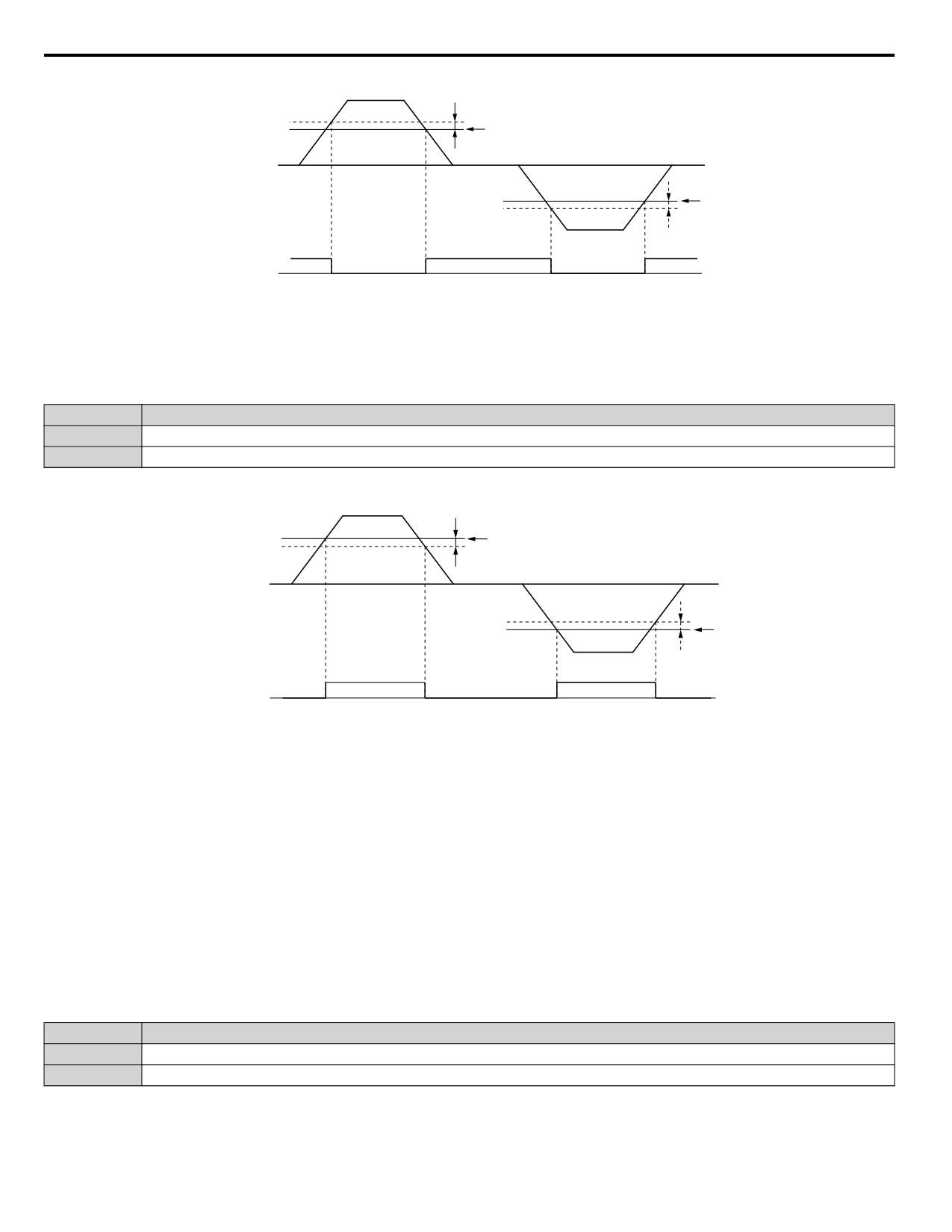
Setting 4: Frequency Detection 1
The output opens when the output frequency rises above the detection level set in L4-01 plus the detection width set in L4-02.
The terminal remains open until the output frequency or motor speed fall below the level set in L4-01.
Status
Description
Open
Output frequency or motor speed exceeded L4-01 + L4-02.
Closed
Output frequency or motor speed is below L4-01 or has not exceeded L4-01 + L4-02.
Note:
Frequency detection works in forward and reverse. The value of L4-01 is used as the detection level for both directions.
5
175
5.7 H: Terminal Functions
Output Frequency
or Motor Speed
L4-02
L4-01
L4-01
L4-02
Frequency
ON
OFF
detection 1
Figure 5.55 Frequency Detection 1 Time Chart
Setting 5: Frequency Detection 2
The output closes when the output frequency is above the detection level set in L4-01. The terminal remains closed until the
output frequency or motor speed fall below L4-01 minus the setting of L4-02.
Status
Description
Open
Output frequency or motor speed is below L4-01 minus L4-02 or has not exceeded L4-01.
Closed
Output frequency or motor speed exceeded L4-01.
Note:
Frequency detection works in forward and reverse. The value of L4-01 is used as the detection level for both directions.
Output Frequency
L4-02
or Motor Speed
L4-01
L4-01
L4-02
Frequency
OFF
ON
Detection 2
Figure 5.56 Frequency Detection 2 Time Chart
Setting 6: Drive Ready
The output closes when the drive is ready to operate the motor. The terminal will not close under the conditions listed below,
and all Run commands will be disregarded.
• When the power is shut off
• During a fault
• When the internal power supply of the drive has malfunctioned
• When a parameter setting error makes it impossible to run
• Although stopped, an overvoltage or undervoltage situation occurs
• While editing a parameter in the Programming Mode (when b1-08 = 0)
Setting 7: DC Bus Undervoltage
The output closes when the DC bus voltage or control circuit power supply drops below the trip level set in L2-05. A fault in
the DC bus circuit will also cause the terminal set for “DC bus undervoltage” to close.
Status
Description
Open
DC bus voltage is above the level set to L2-05.
Closed
DC bus voltage has fallen below the trip level set to L2-05.
Setting 8: During Baseblock (N.O.)
The output closes to indicate that the drive is in a baseblock state. While in baseblock, output transistors do not switch and no
main circuit voltage is output.
176
5.7 H: Terminal Functions
Status
Description
Open
Drive is not in a baseblock state.
Closed
Baseblock is being executed.
Setting 9: Frequency Reference Source
Displays the currently selected frequency reference source.
Status
Description
Open
Frequency reference is provided from External reference 1 (b1-01) or External reference 2 (b1-15).
Closed
Frequency reference is being sourced from the digital operator.
Setting A: Run Command Source
Displays the currently selected Run command source.
Status
Description
Open
Run command is provided from External reference 1 (b1-02) or 2 (b1-16).
Closed
Run command is being sourced from the digital operator.
Settings B, 17, 18, and 19: Torque Detection 1 (N.O., N.C.), Torque Detection 2 (N.O., N.C.)
These digital output functions signal an overtorque or undertorque situation to an external device.
Set up the torque detection levels and select the output function from the table below.
Setting
Status
Description
Torque detection 1 (N.O.):
B
Closed
Output current/torque exceeds (overtorque detection) or is below (undertorque detection) the torque value set in
parameter L6-02 for longer than the time specified in parameter L6-03.
Torque detection 1 (N.C.):
17
Open
Output current/torque exceeds (overtorque detection) or is below (undertorque detection) the torque value set in
parameter L6-02 for longer than the time specified in parameter L6-03.
Torque detection 2 (N.O.):
18
Closed
Output current/torque exceeds (overtorque detection) or is below (undertorque detection) the torque value set in
parameter L6-05 for longer than the time specified in parameter L6-06.
Torque detection 2 (N.C.):
19
Open
Output current/torque exceeds (overtorque detection) or is below (undertorque detection) the torque value set in
parameter L6-05 for longer than the time specified in parameter L6-06.
Setting C: Frequency Reference Loss
An output set for this function closes when frequency reference loss is detected.
Setting D: Braking Resistor Fault
An output programmed for this function closes when the dynamic braking resistor (DB) overheats or the braking transistor is
in a fault condition.
Setting E: Fault
The output closes when the drive faults (excluding CPF00 and CPF01 faults).
Setting F: Through Mode
Select this setting when using the terminal in a pass-through mode. When set to F, an output does not trigger any function in
the drive. Setting F, however, still allows the status of the output terminal (open or closed) to be read by a PLC via a
communication option or MEMOBUS/Modbus communications.
5
Setting 10: Minor Fault (Alarm)
The output closes when a minor fault (alarm) condition is present.
Setting 11: Fault Reset Command Active
The output closes when there is an attempt to reset a fault situation from the control circuit terminals, via serial communications,
or using a communications option card.
Setting 12: Timer Output
This setting configures a digital output terminal as the output for the timer function.
177
5.7 H: Terminal Functions
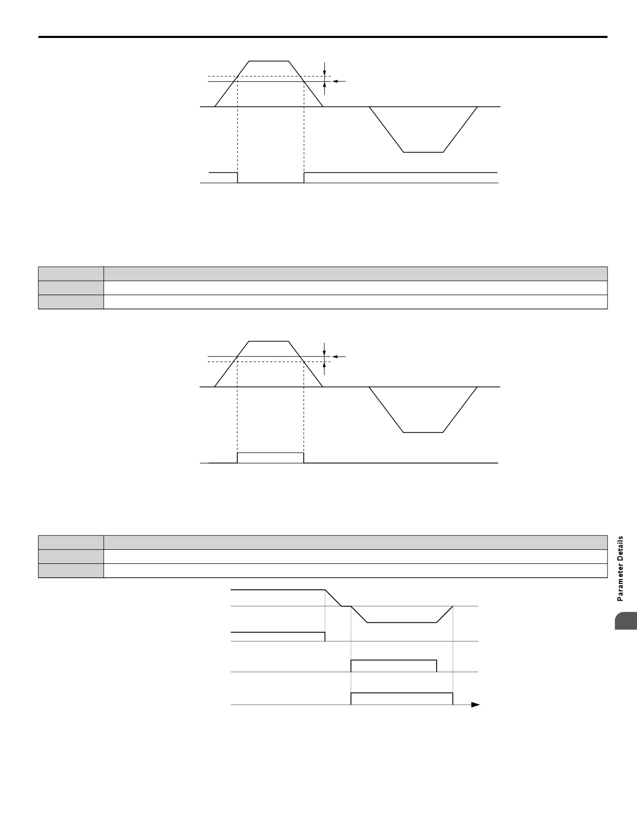
Setting 13: Speed Agree 2 (f
ref /fout Agree 2)
The output closes when the actual output frequency is within the speed agree width (L4-04) of the current frequency reference,
regardless of the direction.
Status
Description
Open
Output frequency or motor speed does not match the frequency reference while the drive is running.
Closed
Output frequency or motor speed is within the range of frequency reference ±L4-04.
Note:
Detection works in forward and reverse.
Frequency
reference
Output Frequency
L4-04
or Motor Speed
L4-04
Speed Agree 2
OFF
ON
Figure 5.57 Speed Agree 2 Time Chart
Setting 14: User-Set Speed Agree 2 (fref /fset Agree 2)
The output closes when the actual output frequency and the frequency reference are within the speed agree width (L4-04) of
the programmed speed agree level (L4-03).
Status
Description
Open
Output frequency or motor speed and frequency reference are both outside the range of L4-03 ±L4-04.
Closed
Output frequency or motor speed and the frequency reference are both within the range of L4-03 ±L4-04.
Note:
The detection level L4-03 is a signed value; detection works in the specified direction only.
Frequency reference + L4-04
Frequency reference
L4-03 + L4-04
Frequency reference - L4-04
L4-03
L4-03 - L4-04
Output frequency
During
Forward
0 Hz
Output frequency
Frequency
reference
User Set
OFF
OFF
ON
ON
Speed Agree 2
Figure 5.58 User-Set Speed Agree 2 Example with a Positive L3-04 Value
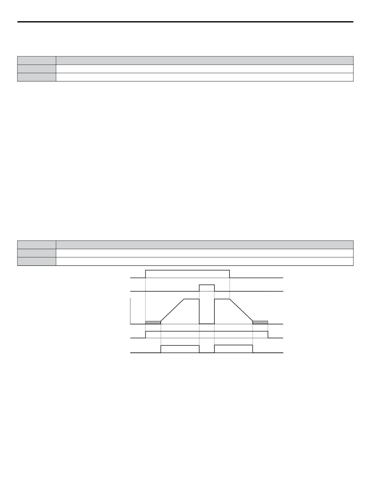
Setting 15: Frequency Detection 3
The output opens when the output frequency rises above the detection level set in L4-03 plus the detection with set in L4-04.
The terminal remains open until the output frequency or motor speed falls below the level set in L4-03. The detection level
L4-03 is a signed value; detection works in the specified direction only.
Status
Description
Open
Output frequency or motor speed exceeded L4-03 plus L4-04.
Closed
Output frequency or motor speed is below L4-03 or has not exceeded L4-03 plus L4-04.
178
5.7 H: Terminal Functions
Output Frequency
or Motor Speed
L4-04
L4-03
Frequency
ON
OFF
detection 3
Figure 5.59 Frequency Detection 3 Example with a Positive L3-04 Value
Setting 16: Frequency Detection 4
The output closes when the output frequency is above the detection level set in L4-03. The terminal remains closed until the
output frequency or motor speed falls below L4-03 minus the setting of L4-04.
Status
Description
Open
Output frequency or motor speed is below L4-03 minus L4-04 or has not exceeded L4-03.
Closed
Output frequency or motor speed exceeded L4-03.
Note:
The detection level L4-03 is a signed value; detection works in the specified direction only.
Output Frequency
L4-04
or Motor Speed
L4-03
Frequency
OFF
ON
Detection 4
Figure 5.60 Frequency Detection 4 Example with Positive L3-04 Value
Setting 1A: During Reverse
A digital output set for “During reverse” closes when the drive is running the motor in the reverse direction.
Status
Description
Open
Motor is being driven in the forward direction or stopped.
Closed
Motor is being driven in reverse.
Output frequency
5
FWD Run command
REV Run command
OFF
ON
During Reverse
time
Figure 5.61 Reverse Direction Output Example Time Chart
179
5.7 H: Terminal Functions
Setting 1B: During Baseblock (N.C.)
The output opens to indicate that the drive is in a baseblock state. While Baseblock is executed, output transistors do not
operate and no main circuit voltage is output.
Status
Description
Open
Baseblock is being executed.
Closed
Drive is not in a baseblock state.
Setting 1E: Restart Enabled
An output set for “Restart enabled” closes when the drive attempts to restart after a fault has occurred.
The fault restart function allows the drive to automatically clear a fault. The terminal set to 1E will close after the fault is
cleared and the drive has attempted to restart. If the drive cannot successfully restart within the number of attempts permitted
by L5-01, a fault will be triggered and the terminal set to 1E will open.
Setting 1F: Motor Overload Alarm (oL1)
The output closes when the motor overload level estimated by the oL1 fault detection exceeds 90% of the oL1 detection level.
Setting 20: Drive Overheat Pre-Alarm (oH)
The output closes when the drive heatsink temperature reaches the level specified by parameter L8-02.
Setting 22: Mechanical Weakening Detection
The output closes when a mechanical weakening situation is detected.
Setting 2F: Maintenance Period
The output closes when the cooling fan, DC bus capacitors, or DC bus pre-charge relay may require maintenance as determined
by the estimated performance life span of those components. Components performance life is displayed as a percentage on
the digital operator screen. Refer to Performance Life Monitors Used for Component Replacement on page 292.
Setting 37: During Frequency Output
The output closes when the drive is outputting a frequency.
Status
Description
Open
Drive is stopped or one of the following functions is being performed: baseblock, DC Injection Braking, Short Circuit Braking.
Closed
Drive is outputting frequency.
OFF
ON
run command
baseblock
OFF
ON
command
output
frequency
OFF
ON
during run
during frequency
OFF
ON
output
Figure 5.62 During Frequency Output Time Chart
Setting 38: Drive Enable
Reflects the status of a digital input configured as a “Drive enable” input (H1-oo = 6A). If that digital input closes, then the
digital output set for “Drive enable” will also close.
Setting 39: Watt Hour Pulse Output
Outputs a pulse to indicate the watt hours.
Setting 3C: LOCAL/REMOTE Status
The output terminal closes while the drive is set for LOCAL and opens when in REMOTE.
180
5.7 H: Terminal Functions
Status
Description
REMOTE: The external reference that has been selected (either b1-01 and b1-02 or b1-15 and b1-16) is used as frequency reference
Open
and Run command source.
Closed
LOCAL: The digital operator is used as frequency reference and Run command source.
Setting 3D: During Speed Search
The output terminal closes while Speed Search is being performed.
Setting 3E: PID Feedback Low
Output terminal closes when a PID feedback loss (FbL) is detected. The feedback is considered to be lost if it falls below the
level set to b5-13 for longer than the time set to b5-14.
Setting 3F: PID Feedback High
Output terminal closes when a PID feedback loss (FbH) is detected. The feedback is considered to be lost if it rises beyond
the level set to b5-36 for longer than the time set to b5-37.
Setting 4A: During KEB Operation
Output terminal closes while KEB is being performed.
Setting 4C: During Fast Stop
Output terminal closes when a Fast Stop is being executed.
Setting 4D: oH Pre-Alarm Time Limit
Output terminal closes when the drive is reducing the speed due to a drive overheat alarm (L8-03 = 4) and the overheat alarm
has not disappeared after 10 frequency reduction operation cycles.
Setting 4E: Braking Transistor Fault (rr)
The output closes if the internal braking transistor reaches the overheat level.
Setting 4F: Braking Resistor Overheat (rH)
Output terminal closes when the braking resistor exceeds the overheat level. The braking resistor may overheat due to motor
regeneration or short deceleration time setting.
Setting 58: Underload Detection
Output terminal closes when the output current falls below the underload detection level defined by L6-14 and L6-02.
Setting 89: Output I Limit
Output terminal closes when drive output speed is being limited due to the output current limit or the single-phase foldback
regulator.
Setting 8B: Lube Pump or Digital Output Delay
Energizes for the time set in parameter P4-31 each time the drive is supposed to start. The drive will delay starting for the
P4-31 time.
Setting 8F: Internal Fan On
Output terminal closes when the internal fan is active.
Setting 91: Pump Fault
Output terminal closes when any of the following faults are active: Low Feedback, High Feedback, Low Water, High Water,
NMS-SetPoint Not Met, POC-Pump Over Cycle, THMS-Thermostat Input, External Pump Fault.
5
Setting 92: Transducer Loss
Output terminal closes the analog input associated with PID feedback has gone above 21mA or below 3mA, or a Transducer
Loss Alarm or Fault is active.
Setting 93: Setpoint Not Met
Output terminal closes during an “NMS - SetPoint Not Met” condition.
Setting 94: Loss of Prime
Output terminal closes during an “LOP - Loss Of Prime” condition.
Setting 95: Volute Thermostat Fault
Output terminal closes when Volute-Thermostat digital input is active.
181
5.7 H: Terminal Functions
Setting 96: High Feedback
Output terminal closes during a “High Feedback Condition” as defined by P1-11 and P1-14, or during a “High FB / Water”
Fault, or during a “High Feedback” Alarm.
Setting 97: Low Feedback
Output terminal closes during a “Low Feedback Condition” as defined by P1-08 and P1-14, or during a “Low FB/Water”
Fault, or during a “Low Feedback” Alarm.
Setting A2: Sleep Active
Output terminal closes when drive is not running due to the Sleep function (does not include Sleep Boost).
Setting A3: Start Delay
Output terminal closes when feedback has risen above the start level (or fallen below the start level for Inverse PID) and the
start timer is timing.
Setting A4: Pre-Charge
Output terminal closes when the drive is in Pre-Charge mode.
Setting A5: Anti-Jam Active
Detects and expels solids that are preventing the pump impeller from turning.
WARNING! Sudden Movement Hazard. The Anti-Jam function can force the motor to briefly run in the reverse direction and may cause
injury even if parameter b1-04 is set to “Reverse Disabled”. Be sure all personnel are clear of rotating machinery.
Setting A9: Thrust Mode
Output terminal closes when the Thrust Bearing feature is active (output frequency is between zero and P4-12).
Setting AA: Utility Start Delay
Output terminal closes when the drive is stopped and waiting for the utility delay timer to expire. This setting is configured
by P4-17.
Settings 100 to 1AA: Functions 0 to AA with Inverse Output
These settings have the same function as settings 0 to AA but with inverse output. Set as 1oo, where the “1” indicates inverse
output and the last two digits specify the setting number of the function.
Examples:
• For inverse output of “8: During baseblock”, set 108.
• For inverse output of “4A: During KEB” set 14A.
n H2-06: Watt Hour Output Unit Selection
When one of the multi-function terminals is set to output the number of watt hours (H2-01/02/03 = 39), parameter H2-06
determines the units for the output signal.
The output is intended to drive a watt hour meter or a PLC input by a 200 ms pulse signal. A pulse is output according to the
kWh unit selected in H2-06.
No.
Parameter Name
Setting Range
Default
0: 0.1 kWh units
1: 1 kWh units
H2-06
Watt Hour Output Unit Selection
2: 10 kWh units
0
3: 100 kWh units
4: 1000 kWh units
n H3-01: Terminal A1 Signal Level Selection
Selects the input signal level for analog input A1.
No.
Name
Setting Range
Default
H3-01
Terminal A1 Signal Level Selection
0, 1
0
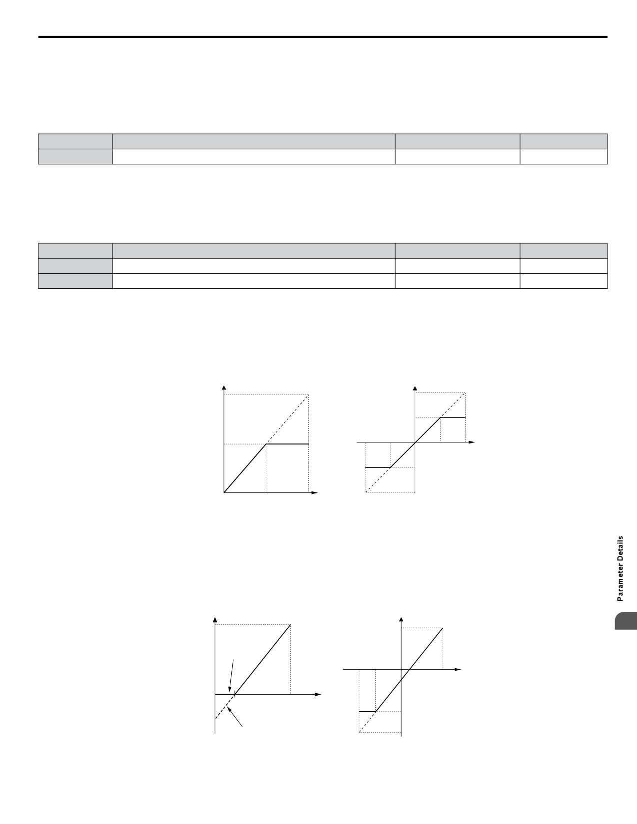
Setting 0: 0 to 10 Vdc
The input level is 0 to 10 Vdc. The minimum input level is limited to 0%, so that a negative input signal due to gain and bias
settings will be read as 0%.
182
5.7 H: Terminal Functions
Setting 1: 0 to 10 Vdc Bipolar
The input level is -10 to 10 Vdc. If the resulting voltage is negative after being adjusted by gain and bias settings, then the
motor will rotate in reverse.
n H3-02: Terminal A1 Function Selection
Selects the input signal level for analog input A1.
No.
Name
Setting Range
Default
H3-02
Terminal A1 Function Selection
0 to 41
0
n H3-03, H3-04: Terminal A1 Gain and Bias Settings
Parameter H3-03 sets the level of the selected input value that is equal to 10 Vdc input at terminal A1 (gain).
Parameter H3-04 sets the level of the selected input value that is equal to 0 V input at terminal A1 (bias).
Use both parameters to adjust the characteristics of the analog input signal to terminal A1.
No.
Name
Setting Range
Default
H3-03
Terminal A1 Gain Setting
-999.9 to 999.9%
100.0%
H3-04
Terminal A1 Bias Setting
-999.9 to 999.9%
0.0%
Setting Examples
•
Gain H3-03 = 200%, bias H3-04 = 0, terminal A1 as frequency reference input (H3-02 = 0):
A 10 Vdc input is equivalent to a 200% frequency reference and 5 Vdc is equivalent to a 100% frequency reference. Since
the drive output is limited by the maximum frequency parameter (E1-04), the frequency reference will be equal to E1-04
above 5 Vdc.
H3-01 = 0
H3-01 = 1
Gain = 200 %
Gain = 200 %
Frequency
100%
reference
E1-04
-10 V
-5 V
100 %
0 V
5 V
10 V
E1-04
-100%
E1-04
Bias = 0 %
Gain = -200 %
0 V
5 V
10 V
Figure 5.63 Frequency Reference Setting by Analog Input with Increased Gain
•
Gain H3-03 = 100%, bias H3-04 = -25%, terminal A1 as frequency reference input:
An input of 0 Vdc will be equivalent to a -25% frequency reference.
When parameter H3-01 = 0, the frequency reference is 0% between 0 and 2 Vdc input.
When parameter H3-01 = 1, the motor will rotate in reverse between -10 and 2 Vdc input.
H3-01 = 0
H3-01 = 1
100 %
5
100%
Frequency
H3-01 = 0
reference
-10 V -6.0 V
2.0 V
10 V
-25%
Analog Input
Voltage
0
2.0 V
10 V
Analog Input
-100%
-25%
Voltage
E1-04
H3-01 = 1
-150%
Figure 5.64 Frequency Reference Setting by Analog Input with Negative Bias
183
5.7 H: Terminal Functions
n H3-09: Terminal A2 Signal Level Selection
Selects the input signal level for analog input A2. Set DIP Switch S1-2 on the terminal board accordingly for a voltage input
or current input.
No.
Name
Setting Range
Default
H3-09
Terminal A2 Signal Level Selection
0 to 3
2
Setting 0: 0 to 10 Vdc
The input level is 0 to 10 Vdc. Refer to Setting 0: 0 to 10 Vdc on page 182.
Setting 1: 0 to 10 Vdc Bipolar
The input level is -10 to 10 Vdc. Refer to Setting 1: 0 to 10 Vdc Bipolar on page 183.
Setting 2: 4 to 20 mA
The input level is 4 to 20 mA. Negative input values by negative bias or gain settings will be limited to 0%.
Setting 3: 0 to 20 mA
The input level is 0 to 20 mA. Negative input values by negative bias or gain settings will be limited to 0%.
n H3-10: Terminal A2 Function Selection
Determines the function assigned to analog input terminal A2.
No.
Name
Setting Range
Default
H3-10
Terminal A2 Function Selection
0 to 32
B
n H3-11, H3-12: Terminal A2 Gain and Bias Setting
Parameter H3-11 sets the level of the input value selected that is equal to 10 Vdc input or 20 mA input to terminal A2.
Parameter H3-12 sets the level of the input value selected that is equal to 0 V, 4 mA or 0 mA input at terminal A2.
Use both parameters to adjust the characteristics of the analog input signal to terminal A2. The setting works in the same way
as parameters H3-03 and H3-04 for analog input A1.
No.
Name
Setting Range
Default
H3-11
Terminal A2 Gain Setting
-999.9 to 999.9%
100.0%
H3-12
Terminal A2 Bias Setting
-999.9 to 999.9%
0.0%
n H3-13: Analog Input Filter Time Constant
Parameter H3-13 sets the time constant for a first order filter that will be applied to both analog inputs A1 and A2.
No.
Name
Setting Range
Default
H3-13
Analog Input Filter Time Constant
0.00 to 2.00 s
0.03 s
An analog input filter can be used to prevent erratic drive control when a “noisy” analog reference is used. The drive operation
becomes more stable the longer the time programmed, but it becomes less responsive to rapidly changing analog signals.
n Multi-Function Analog Input Terminal Settings for A1 and A2 (H3-02 and H3-10)
This section describes the various functions that can be assigned to terminals A1 and A2 by setting H3-02 and H3-10.
Note:
The scaling of all input functions depends on the gain and bias settings for the analog inputs. Set these to appropriate values when selecting
and adjusting analog input functions.
Table 5.25 Multi-Function Input Terminal Settings
Setting
Function
Page
Setting
Function
Page
0
Frequency Bias
185
E
Motor Temperature (PTC input)
185
1
Frequency Gain
185
F
Not Used
185
2
Auxiliary Frequency Reference
185
16
Differential PID Feedback
185
4
Output Voltage Bias
185
1F
Not Used
185
7
Overtorque/Undertorque Detection Level
185
20
HAND Frequency Reference
185
B
PID Feedback
185
41
Output Voltage Gain
185
C
PID Setpoint
185
184
5.7 H: Terminal Functions
Setting 0: Frequency Bias
The input value of an analog input set to this function will be added to the analog frequency reference value. Use this setting
also when only one analog input is used to supply the frequency reference.
By default both analog inputs A1 and A2 are set for this function. Using both A1 and A2 at the same time increases the
frequency reference by the total of both inputs.
Example: If the analog frequency reference by analog input A1 is 50% and a bias of 20% is applied by analog input A2, the
resulting frequency reference will be 70% of the maximum output frequency.
Setting 1: Frequency Gain
The input value of an analog input set to this function will be multiplied with the analog frequency reference value.
Example: If the analog frequency reference from analog input A1 is 80% and a gain of 50% is applied from analog input A2,
the resulting frequency reference will be 40% of the maximum output frequency.
Setting 2: Auxiliary Reference
Sets the auxiliary frequency reference when Multi-Step Speed operation is selected. Refer to Multi-Step Speed Selection on
page 147 for details.
Setting 4: Voltage Bias
Voltage bias boosts the output voltage of the V/f curve as a percentage of the maximum output voltage (E1-05). Available
only when using V/f Control.
Setting 7: Overtorque/Undertorque Level
Overtorque level sets the overtorque/undertorque detection level using the analog input. This works with Torque Detection
Selection 1 (L6-01) and will take the place of the torque detection level set to L6-02. For V/f Control, this function is based
on 100% of the drive rated current. Refer to L6: Torque Detection on page 205 for details on torque detection.
Setting B: PID Feedback
An input set for this function supplies the PID feedback value. This setting requires PID operation to be enabled in b5-01.
Refer to PID Feedback Input Methods on page 131.
Setting C: PID Setpoint
An input set for this function supplies the PID setpoint value. The frequency reference selected in parameter b1-01 no longer
becomes the PID se point. This setting requires PID operation to be enabled in b5-01. Refer to PID Setpoint Input
Methods on page 131.
Setting E: Motor Temperature
In addition to or in place of the oL1 (motor overload) fault detection, it is possible to use a PTC (Positive Temperature
Coefficient) thermistor for motor insulation protection. Refer to Motor Protection Using a Positive Temperature Coefficient
(PTC) on page 191 for detailed explanations.
Setting F: Not Used
Any analog input that is not used should be set to F. When set to “F”, an input does not affect any drive function but the input
level can be read out by a PLC via a communication option or MEMOBUS/Modbus communications (through mode). This
way drive analog inputs can be used to read out external sensor values if there is a lack of PLC analog inputs.
Setting 16: Differential PID Feedback
If an analog value is set for this function, the PID controller is set for differential feedback. The subtraction of the PID feedback
input value and the differential feedback input value builds the feedback value that is used to calculate the PID input. Refer
to PID Feedback Input Methods on page 131.
5
Setting 1F: Not Used
An input does not affect any drive function, but the input level can still be read out by a PLC via a communication option or
MEMOBUS/Modbus communications.
Setting 20: HAND Frequency Reference
Provides the HAND frequency reference when HAND Mode Frequency Reference Source parameter P5-01 is set to 1.
Setting 41: Output Voltage Gain
Allows the user to change the output voltage by adjusting the voltage reference via one of the analog input terminals or with
MEMOBUS/Modbus.
185
5.7 H: Terminal Functions
An internal 0.3 second delay has been added to prevent sudden, drastic change to the V/f pattern.
Note:
When an input terminal is assigned to adjust the Output Voltage Gain (H3-oo = 41), a voltage reference from MEMOBUS/Modbus is
ignored.
n H3-14: Analog Input Terminal Enable Selection
Determines which of the analog input terminals will be enabled or disabled when a digital input programmed for “Analog
input enable” (H1-oo = C) is closed. When H1-oo ≠ C, all of the input terminals are enabled all of the time. Terminals not
set as the target are not influenced by input signals.
No.
Name
Setting Range
Default
H3-14
Analog Input Terminal Enable Selection
1, 2, 7
7
Setting 1: Terminal A1 only
Setting 2: Terminal A2 only
Setting 7: All Terminals Enabled
n H3-16/H3-17: Terminal A1/A2 Offset
Determines the amount of offset to be used to calibrate analog input signals from the terminals A1 and A2.
Enter a 0 V signal to terminal A1. Next adjust the offset in H3-16 until the monitor U1-13 for the terminal A1 input voltage
reads 0.0%.
The process is the same for terminal A2. Enter a 0 V signal, and adjust the offset for terminal A2 in H3-17 until the monitor
U1-14 for terminal A2 input voltage reads 0.0%.
No.
Name
Setting Range
Default
H3-16
Terminal A1 Offset
-500 to 500
0
H3-17
Terminal A2 Offset
-500 to 500
0
u H4: Multi-Function Analog Output Terminals
These parameters assign a function to analog output terminal AM for monitoring a specific aspect of drive performance.
n H4-01: Multi-Function Analog Terminal AM Monitor Selection
Sets the desired drive monitor parameter Uo-oo to output as an analog value via terminal AM. Refer to U: Monitors on
page 369 for a list of all monitors. The “Analog Output Level” columns indicates if a monitor can be applied for analog output.
Example: Enter “103” for U1-03.
No.
Name
Setting Range
Default
H4-01
Multi-Function Analog 1 (Terminal AM Monitor Selection)
000 to 999
102
A setting of 031 or 000 applies no drive monitor to the analog output. With this setting the terminal AM output level can be
set by a PLC via a communication option or MEMOBUS/Modbus communications (through mode).
n H4-02/H4-03: Multi-Function Analog Output Terminal AM Gain/Bias
Parameter H4-02 sets the output voltage that is equal to 100% of the monitor value. Parameter H4-03 sets the output voltage
equal to 0% of the monitor value.
Both values are set as a percentage of 10 V. The minimum output voltage for terminal AM is 0 V, the maximum is 10 Vdc.
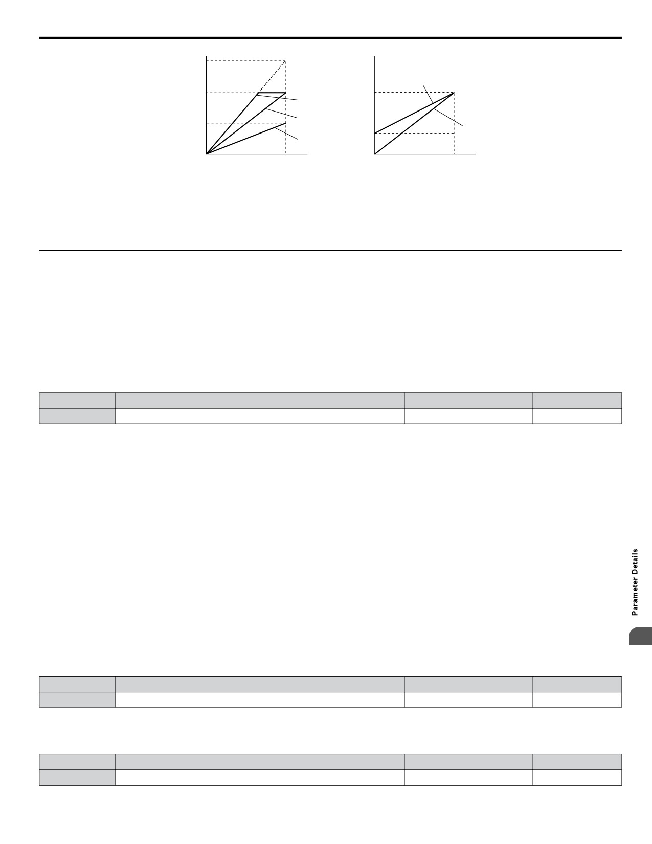
Figure 5.65 illustrates the function of the gain and bias settings.
No.
Name
Setting Range
Default
H4-02
Multi-Function Analog Output Terminal AM Gain
-999.9 to 999.9%
100.0%
H4-03
Multi-Function Analog Output Terminal AM Bias
-999.9 to 999.9%
0.0%
186
5.7 H: Terminal Functions
Bias
30%
Gain 100%
10 V
10 V
Gain 150%
Terminal AM
Bias 0%
Terminal AM
output
output
voltage
voltage
Gain 100%
5 V
Bias 0%
Bias 0%
3 V
Gain 100%
Gain 50%
Bias 0%
0 V
0 V
0%
Monitor value
100%
0%
Monitor value
100%
Figure 5.65 Analog Output Gain/Bias Setting
When viewing the settings for H4-02, terminal AM will output a voltage that is equal to 100% of the monitor value (considering
the present setting). When viewing the settings for H4-03, terminal AM will output a voltage that is equal to 0% of the monitor
value.
u H6: Pulse Train Input/Output
A one track pulse train signal with a maximum frequency of 32 kHz can be input to the drive at terminal RP. This pulse train
signal can be used as the frequency reference, for PID functions, or as the speed feedback signal in V/f Control.
The pulse output monitor terminal MP, which can be used in sinking or sourcing mode, can output drive monitors values as
a pulse train signal with a maximum frequency of 32 kHz.
Use parameters H6-oo to scale and set up the function for the pulse input terminal RP and pulse output terminal MP.
n H6-01: Pulse Train Input Terminal RP Function Selection
Selects the function of pulse train input terminal RP.
No.
Name
Setting Range
Default
H6-01
Pulse Train Input Terminal RP Function Selection
0 to 4
0
Setting 0: Frequency Reference
If the pulse input is set for this function and the frequency reference source is set to pulse input (b1-01/15 = 4), the drive reads
the frequency value from terminal RP.
Setting 1: PID Feedback Value
Using this setting, the feedback value for PID control can be supplied as a pulse signal at terminal RP. Refer to b5: PID
Control on page 129 for details on PID control.
Setting 2: PID Setpoint Value
Using this setting, the setpoint value for PID control can be supplied as a pulse signal at terminal RP. Refer to b5: PID
Control on page 129 for details on PID control.
Setting 3: Speed Feedback for V/f Control (V/f Control only, Motor 1 only)
This setting enables simple speed feedback for V/f Control. A pulse signal can be used to input the motor speed to the drive
and thereby improve the speed control accuracy. Note that this speed feedback can only be a one track signal that cannot be
used for direction detection. The drive needs a separate motor rotation direction signal.
n H6-02: Pulse Train Input Terminal RP Scaling
5
The pulse train input scaling parameter sets the terminal RP input frequency that is equal to 100% of the signal selected as the
input value in parameter H6-01.
No.
Name
Setting Range
Default
H6-02
Pulse Train Input Scaling
100 to 32000 Hz
1440 Hz
n H6-03: Pulse Train Input Terminal RP Gain
Sets the level of the value selected in H6-01 when a pulse train signal with the frequency set in H6-02 is input to terminal RP.
No.
Name
Setting Range
Default
H6-03
Pulse Train Input Gain
0.0 to 1000.0%
100.0%
187
5.7 H: Terminal Functions
n H6-04: Pulse Train Input Terminal RP Bias
Sets the level of the value selected in H6-01 when a 0 Hz signal is input to terminal RP.
No.
Name
Setting Range
Default
H6-04
Pulse Train Input Bias
-100.0 to 100.0%
0.0%
n H6-05: Pulse Train Input Terminal RP Filter Time
Sets the pulse train input filter time constant in seconds.
The pulse train input filter helps prevent noise interference from causing erroneous operation when operating the drive within
the pulse train signal.
Increasing the filter setting time increases the effectiveness of the noise prevention, however, this also increasingly slows drive
response time.
No.
Name
Setting Range
Default
H6-05
Pulse Train Input Filter Time
0.00 to 2.00 s
0.10 s
n H6-06: Pulse Train Output Terminal MP Monitor Selection
Selects the pulse train monitor output terminal MP function. The set value ooo is equal to the numerals in Uo-oo of the
selected monitor. Refer to U: Monitors on page 369 for a complete list of monitors. Selectable monitor items are listed below.
No.
Name
Setting Range
Default
000, 031, 101, 102, 105, 116,
H6-06
Pulse Train Output Terminal MP Monitor Selection
102
501, 502, 801 to 809
n H6-07: Pulse Train Output Terminal MP Monitor Scaling
Pulse train monitor scaling sets the output frequency at terminal MP when the monitor item is 100%. Set H6-06 to 102 and
H6-07 to 0 to make the pulse train monitor output synchronous to the output frequency.
No.
Name
Setting Range
Default
H6-07
Pulse Train Input Monitor Scaling
0 to 32000 Hz
1440 Hz
n H6-08: Pulse Train Input Minimum Frequency
Sets the minimum output frequency detected by the pulse train input. Increasing this setting reduces the time the drive needs
to react to changes in the input signal.
• The pulse input value becomes 0 when the pulse input frequency falls below this level.
• Enabled when H6-01 = 0, 1, or 2.
• When simple speed feedback in V/f Control is set as the function for terminal RP (H6-01 = 3), the minimum frequency
becomes the detection time for PG disconnect (F1-14).
No.
Name
Setting Range
Default
H6-08
Pulse Train Input Minimum Frequency
0.1 to 1000.0 Hz
0.5 Hz
188
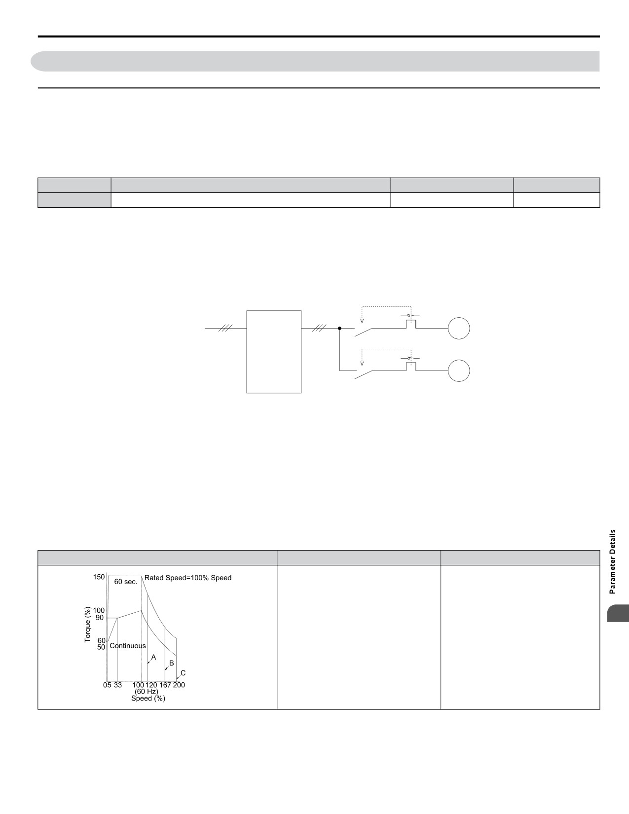
5.8 L: Protection Functions
5.8
L: Protection Functions
u L1: Motor Protection Functions
n L1-01: Motor Overload Protection Selection
The drive has an electronic overload protection function that estimates the motor overload level based on output current, output
frequency, thermal motor characteristics, and time. An oL1 fault will be triggered when motor overload is detected.
L1-01 sets the overload protection function characteristics according to the motor being used.
No.
Name
Setting Range
Default
L1-01
Motor Overload Protection Selection
0 to 3; 6
1
Note:
1. When the motor protection function is enabled (L1-01 is not set to zero), an oL1 alarm can be output through one of the multi-function
outputs by setting H2-01 to 1F. The output will close when the motor overload level reaches 90% of the oL1 detection level.
2. Select a method to protect the motor from overheat by setting L1-01 to a value between 1 and 3; use setting 6 when running a single
motor from the drive. An external thermal relay is not required.
Setting 0: Disabled - Motor Overload Protection is not Provided
This setting should be used if no motor overheat protection is desired or if multiple motors are connected to one drive. In this
case it is recommended that you install a thermal relay for each motor as show in Figure 5.66
Drive
Power
M1
supply
MC1
L10
M2
MC2
L20
MC1, MC2: Magnetic contactors
L10, L20: Thermal relays
Figure 5.66 Example of Protection Circuit Design for Multiple Motors
NOTICE: Protect each motor with individual thermal overloads when multiple motors are connected to one drive. Failure to comply could
result in motor damage. Disable the electronic overload protection of the drive (L1-01 = “0: Disabled”) and protect each motor with individual
motor thermal overloads.
Setting 1: General Purpose Motor (standard self-cooled)
Because the motor is self-cooled, the overload tolerance drops when the motor speed is lowered. The drive appropriately
adjusts the electrothermal trigger point according to the motor overload characteristics, protecting the motor from overheat
throughout the entire speed range.
Overload Tolerance
Cooling Ability
Overload Characteristics
Motor designed to operate from line
Continuous operation at less than line
5
power.
power frequency with 100% load can
Motor cooling is most effective when
trigger motor overload protection
running at rated nameplate base
(oL1). A fault is output and the motor
frequency (check the motor
will coast to stop.
specifications).
Setting 2: Drive Dedicated Motor (constant torque, 1:10)
Use this setting when operating a drive duty motor with a torque ratio of 1:10. This motor type is allowed to run with 100%
load from 10% up to 100% speed. Running slower speeds with full load can trigger an overload fault.
189
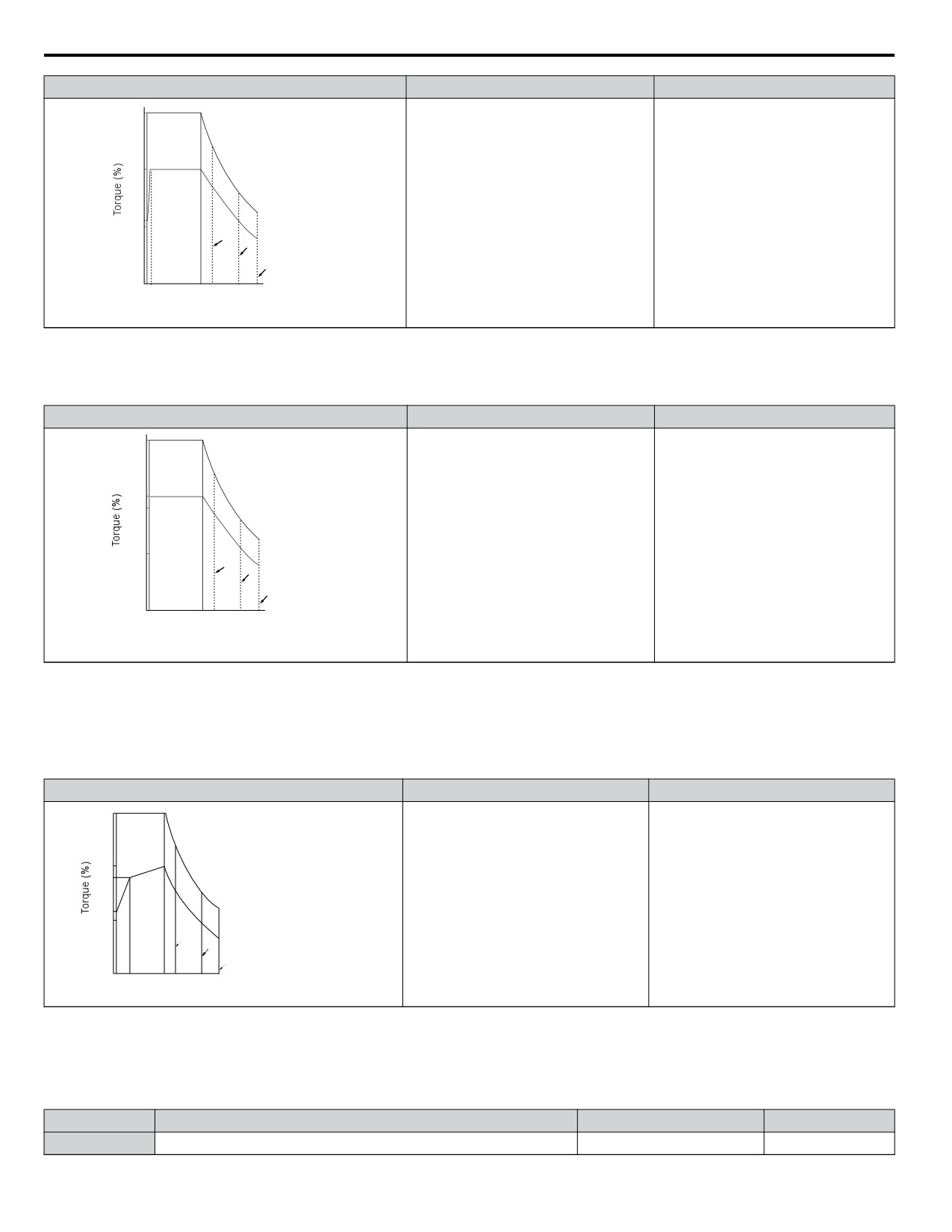
5.8 L: Protection Functions
Overload Tolerance
Cooling Ability
Overload Characteristics
150
Rated Speed=100% Speed
60 sec.
100
Motor is designed to effectively cool
Continuous operation with 100% load
55
itself at speeds as low as 6 Hz.
from 6 Hz to 50/60 Hz.
50
A
Continuous
D
B
0
110
100120 167 200
(60 Hz)
Speed (%)
Setting 3: Vector Motor (constant torque, 1:100)
Use this setting when operating a drive dedicated motor with a torque ratio of 1:100. This motor type is allowed to run with
100% load from 1% up to 100% speed. Running slower speeds with full load can trigger an overload fault.
Overload Tolerance
Cooling Ability
Overload Characteristics
150
Rated Speed=100% Speed
60 sec.
100
90
Motor is designed to effectively cool
Continuous operation with 100% load
itself at speeds as low as approximately
50
Continuous
from 0.6 Hz to 50/60 Hz.
A
0.6 Hz.
B
D
0
1
100120 167 200
(60 Hz)
Speed (%)
Setting 6: General-Purpose Motor
Note:
General-purpose motors are designed with a base speed that operates at line frequency (50/60 Hz depending on geographic region).
Because the motor is self-cooled, the overload tolerance drops when the motor speed is lowered. The drive appropriately
adjusts the electrothermal trigger point according to the motor overload characteristics and protects the motor from overheat
throughout the entire speed range.
Overload Tolerance
Cooling Ability
Overload Characteristics
150
Rated Speed=100% Speed
60 s
A: Max. speed for 200LJ and above
B: Max. speed for 160MJ to 180 LJ
100
C: Max. speed for 132MJ and below
90
Motor designed to operate from line
Continuous operation at less than line
power. Motor cooling is most effective
power frequency with 100% load can
when running at rated base frequency
trigger motor overload protection
60
50
Continuous
(check the motor nameplate or
(oL1). A fault is output and the motor
A
specifications)
will coast to stop.
B
C
05 33
100 120 167 200
Speed (%)
n L1-02: Motor Overload Protection Time
Sets the time for the drive to shut down on motor overload (oL1) when the motor is running with excessive current. Enter the
time the motor can withstand operating at 150% current after previously running at 100% current (hot motor overload
condition). This parameter rarely requires adjustment.
No.
Name
Setting Range
Default
L1-02
Motor Overload Protection Time
0.1 to 5.0 minutes
1.0 minutes
190
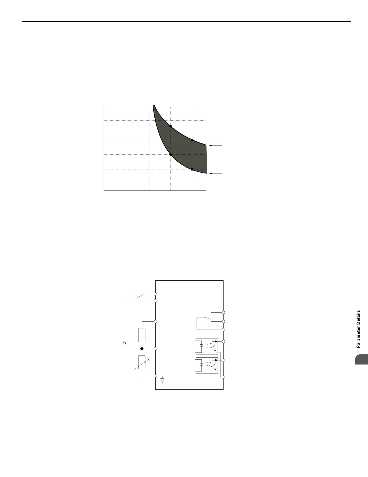
5.8 L: Protection Functions
Defaulted to operate with an allowance of 150% overload operation for one minute in a hot start after continuous operation
at 100%.
Figure 5.67 illustrates an example of the electrothermal protection operation time using a general-purpose motor operating at
the value of E1-06, Motor Base Speed, with L1-02 set to one minute.
Motor overload protection operates in the area between a cold start and a hot start.
• Cold start: Characteristics of motor protection operation time in response to an overload situation that was suddenly reached
when starting a stationary motor.
• Hot start: Characteristics of motor protection operation time in response to an overload situation that occurred while the
motor was operating continuously at or below its rated current.
Operation time (minutes)
10
7
3
Cold start
(characteristics when an
overload occurs at a
1
complete stop)
Hot start
0.4
(characteristics when an
overload occurs during
continuous operation at 100%)
0.1
Motor current (%)
0
100
150
200
E2-01 = 100% motor current
Figure 5.67 Protection Operation Time for General Purpose Motors at the Rated Output Frequency
n Motor Protection Using a Positive Temperature Coefficient (PTC)
A motor PTC can be connected to an analog input of the drive. This input is used by the drive for motor overheat protection.
When the motor overheat alarm level is reached, an oH3 alarm will be triggered and the drive will continue operation as
selected in L1-03. When the overheat fault level is reached an oH4 fault is triggered, a fault signal will be output and the drive
will stop the motor using the stop method determined in L1-04.
Figure 5.68 shows a PTC connection example for analog input A2. If using analog input A2, make sure to set DIP switch S1
on the terminal board for voltage input when using this function.
Multi-function input
Drive
MA
+V
Multi-function
MB
(+10.5V, 20 mA )
output (contact)
MC
Branch
resistor
P1
12 k
A2 (0-10 V)
PTC
P2
Multi-function
5
thermistor
output (photocoupler)
AC
PC
Figure 5.68 Connection of a Motor PTC
The PTC must have the following characteristics for one motor phase. Normally a motor is protected by three PTCs connected
in series.
191
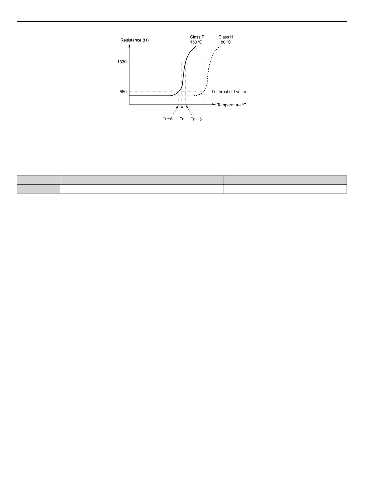
5.8 L: Protection Functions
Tr’
Figure 5.69 Motor PTC Characteristics
Overheat detection using a PTC can be set up by parameters L1-03/04/05 as explained below.
n L1-03: Motor Overheat Alarm (oH3) Operation Selection
Sets the drive operation when the PTC input signal reaches the motor overheat alarm level. (PTC input level: Tr - 5 °C)
No.
Name
Setting Range
Default
L1-03
Motor Overheat Alarm Operation Selection
0 to 3
3
Setting 0: Ramp to Stop
The drive stops the motor using the active deceleration time.
Setting 1: Coast to Stop
The drive output is switched off and the motor coasts to stop.
Setting 2: Fast-stop
The drive stops the motor using the Fast-stop time set in parameter C1-09.
Setting 3: Alarm Only
The operation is continued and an oH3 alarm is displayed on the digital operator
192
5.8 L: Protection Functions
n L1-04: Motor Overheat Fault (oH4) Operation Selection
Sets the drive operation when the PTC input signal reaches the motor overheat fault level. (PTC input level: Tr + 5 °C)
No.
Name
Setting Range
Default
L1-04
Motor Overheat Fault Operation Selection
0 to 2
1
Setting 0: Ramp to Stop
The drive stops the motor using the active deceleration time.
Setting 1: Coast to Stop
The drive output is switched off and the motor coasts to stop.
Setting 2: Fast-stop
The drive stops the motor using the Fast-stop time set in parameter C1-09.
n L1-05: Motor Temperature Input Filter Time
Used to set a filter on the PTC signal in order to prevent a motor overheat fault from being mistakenly detected.
No.
Name
Setting Range
Default
L1-05
Motor Temperature Input Filter Time
0.00 to 10.00 s
0.20 s
n L1-13: Continuous Electrothermal Operation Selection
Determines whether to hold the current value of the electrothermal motor protection (L1-01) when the power supply is
interrupted.
No.
Name
Setting Range
Default
L1-13
Continuous Electrothermal Operation Selection
0 or 1
1
Setting 0: Disabled
Setting 1: Enabled
n L1-22: Leakage Current Filter Time Constant 1
Note:
Available only when C6-02 is set to B. To display this parameter, first set C6-02 to B.
Sets the time constant for the filter applied to motor overload detection current or monitor current for constant speed operation.
Leakage current can incorrectly trigger motor overload fault oL1 or result in incorrect monitor reading. Increase this setting
if erroneous detection occurs or if the monitor display is incorrect.
NOTICE: Setting parameter L1-22 too high may cause the drive to detect motor overload too slowly and burn out the motor. Be sure to set
L1-22 to an appropriate value for the application.
No.
Name
Setting Range
Default
L1-22
Leakage Current Filter Time Constant 1
0.0 to 60.0 s
20.0 s
n L1-23: Leakage Current Filter Time Constant 2
Note:
Available only when C6-02 is set to B. To display this parameter, first set C6-02 to B.
Sets the time constant for the filter applied to monitor current during acceleration and deceleration. Leakage current can result
in incorrect monitor reading. Increase this setting if the monitor display is incorrect.
Note:
Setting parameter L1-23 too high may cause the current monitor to take too long to read the initial current level. Check the operation sequence
5
being used if this is a problem.
No.
Name
Setting Range
Default
L1-23
Leakage Current Filter Time Constant 2
0.0 to 60.0 s
1.0 s
u L2: Momentary Power Loss Ride-Thru
n L2-01: Momentary Power Loss Operation Selection
When a momentary power loss occurs (DC bus voltage falls below the level set in L2-05), the drive can be set to automatically
return to the operation it was performing when the power went out based on certain conditions.
193
5.8 L: Protection Functions
No.
Name
Setting Range
Default
L2-01
Momentary Power Loss Operation Selection
0 to 2
0
Setting 0: Disabled (default)
If power is not restored within 15 ms, a Uv1 fault will result and the drive will stop the motor.
Setting 1: Enabled, Recover Within L2-02
When a momentary power loss occurs, the drive will attempt to restart and perform Speed Search if power is restored within
the period of time set to parameter L2-02. If power is not restored within the time set to L2-02 (i.e. DC bus voltage level
remains below Uv1 detection level L2-05), then a Uv1 fault is triggered and the drive output will be shut off.
Setting 2: Recover as Long as CPU has Power
Drive will try to restart as long as the CPU still has power. This allows for a longer ride-through time than setting L2-01 to 1.
A Uv1 fault is not triggered. This setting should also be used if the KEB function is utilized.
Note:
1. The amount of time the drive is capable of recovering after a power loss is determined by the capacity of the drive. Drive capacity
determines the upper limit for L2-02.
2. When L2-01 is set to 1 or 2, and a magnetic contactor between motor and drive is used, be sure that the magnetic contactor is kept close
as long as the drive attempts to restart.
3. When L2-01 is set to 1 or 2, “Uv” will flash on the operator while the drive is attempting to recover from a momentary power loss. A
fault signal is not output at this time.
n L2-02: Momentary Power Loss Ride-Thru Time
Set the time in which the power has to return before a Uv fault is tripped. This parameter is valid only if L2-01 = 1.
No.
Name
Setting Range
Default
Determined by
L2-02
Momentary Power Loss Ride-Thru Time
0.0 to 25.5 s
o2-04.
n L2-03: Momentary Power Loss Minimum Baseblock Time
Sets the minimum baseblock time when power is restored following a momentary power loss. This determines the time it takes
for the leftover voltage in the motor to dissipate. Increase this setting if overcurrent or overvoltage occur at the beginning of
Speed Search after a power loss or DC Injection Braking. If L2-03 > L2-02, then the drive will restart after the time set to
L2-03 has passed from the beginning of the power loss.
No.
Name
Setting Range
Default
Determined by
L2-03
Momentary Power Loss Minimum Baseblock Time
0.1 to 5.0 s
o2-04
n L2-04: Momentary Power Loss Voltage Recovery Ramp Time
Sets the time constant used to ramp up the voltage during Speed Search. The setting value determines the time for a change
from zero to the maximum voltage.
No.
Name
Setting Range
Default
Determined by
L2-04
Momentary Power Loss Voltage Recovery Ramp Time
0.0 to 5.0 s
o2-04
n L2-05: Undervoltage Detection Level
Determines the voltage at which a Uv1 fault is triggered or at which the KEB function is activated.
No.
Name
Setting Range
Default
L2-05 <1>
Undervoltage Detection Level
150 to 210 V
190 V <2>
<1> Values are for 200 V class drives and must be doubled for 400 V class drives.
<2> This value is initialized when E1-01 is changed.
This setting rarely needs to be changed.
When setting L2-05 is lower than the default setting, be sure to install an AC reactor option to the input side of the power
supply to prevent damage to drive circuitry.
194
5.8 L: Protection Functions
n Kinetic Energy Backup (KEB) Function
In case of a power loss, the KEB function can decelerate the motor and use the rotational energy of the machine to backup/
maintain the drive DC bus for a certain period of time. This allows the drive to continue running without interrupting the output
power during a momentary power loss. Once the power is restored, the drive smoothly returns to the same operational state
before the power loss occurred. The KEB function supports two different operation modes.
KEB 1
In this mode the drive decelerates the motor based on the deceleration time set in parameter L2-06/C1-09 in order to keep the
DC bus voltage level high. When the power supply returns, it uses the time set to L2-07 or the selected acceleration time to
accelerate back to the frequency reference.
OFF
ON
OFF
KEB Ride-Thru
(H1-oo = 65 or 66)
Output
frequency
L2-06
L2-07
Figure 5.70 KEB Ride-Thru Timing Diagram for Multiple Drives
Note:
If L2-06 is set to 0.0 s, C1-09 is used instead. If L2-07 is set to 0.0 s, the drive reaccelerates using the selected acceleration time.
Use this method with setting parameters L2-06 and L2-07 if multiple drives must decelerate but still keep the speed ratio
between the drives constant during power loss. In this case, a braking resistor is required in order to avoid overvoltage trips.
KEB 2
In this mode the drive decelerates the motor by calculating the energy of the rotating system. The deceleration rate is
continuously adjusted so that the DC bus voltage meets the level set in parameter L2-11. The rotational energy is estimated
using the parameters L3-24 and L3-25. When the power supply returns, the drive accelerates back to the frequency reference
using the selected acceleration time.
Activation and Deactivation of the KEB Function
The KEB function requires parameter L2-01 to be set to 1 or 2 and a digital input has to be configured for the KEB 1
(H1-oo = 65/66) or KEB 2 (H1-oo = 7A/7B) command. The input has to be enabled during KEB. Refer to Settings 65
and 66: KEB Ride-Thru 1 (N.C.), 2 (N.O.) on page 170 and Refer to Settings 7A and 7B: KEB Ride-Thru 2 (N.C., N.O.)
on page 172 for details on setting the KEB input commands.
The KEB function is automatically activated when one of the conditions below becomes true.
• The DC bus voltage falls below the level set in parameter L2-05. The KEB input has to be set within 50 ms after the KEB
function was activated, or the drive will assume the power supply has returned and attempt to restart.
• The input programmed for KEB 1 or 2 is activated. This input should be triggered by an external undervoltage detection
relay.
The KEB function ends when one of the conditions below become true.
• The KEB input was released or
• The function was activated by DC bus voltage detection and no KEB input was set within 50 ms after the KEB activation.
5
Figure 5.71 shows a wiring example for triggering the KEB function at power loss using digital input S6.
195
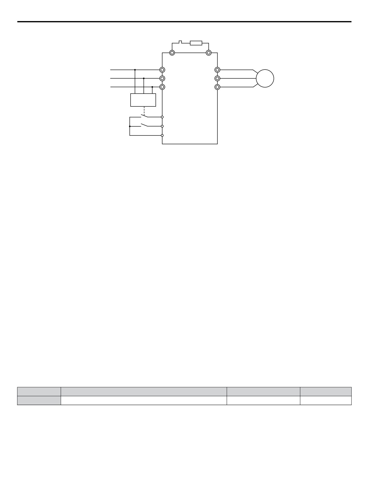
5.8 L: Protection Functions
Braking
Resistor
B1
B2
L1
R/L1
U/T1
L2
S/L2
V/T2
M
L3
T/L3
W/T3
UV Detection
Relay
S6 - KEB command 1 or 2
S1 - Start command
SC
Figure 5.71 KEB Function Wiring Example
Note:
Make sure the Run command is not switched off when momentary power loss occurs. If the Run command is shut off, the drive will not
accelerate back to speed when the power is restored.
KEB Related Adjustment Parameters
The KEB 1 functions can be adjusted using the following parameters:
• L2-05, Undervoltage Detection Level
• L2-06 or C1-09, KEB Deceleration Time or Fast-stop Time
• L2-07, KEB Acceleration Time
• L2-08, Frequency Gain at KEB Start
Use the following parameters when adjusting the KEB 2 function:
• L2-05, Undervoltage Detection Level
• L2-08, Frequency Gain at KEB Start
• L2-11, Desired DC Bus Voltage during KEB
• L3-20, Main Circuit DC Voltage Adjustment Gain
Sets the proportional gain for controlling the DC bus voltage and keeping it at the desired level during KEB 2 operation.
• L3-21, Accel/Decel Rate Calculation Gain
Sets the gain used to calculate the acceleration or deceleration rate when KEB 2 is active.
• L3-24, Motor Acceleration Time
This value is used to estimate the regenerative power fed back from the mechanics to the drive DC bus during KEB 2.
• L3-25, Load Inertia Ratio
This value is used to estimate the regenerative power fed back from the mechanics to the drive DC bus during KEB 2.
n L2-06: KEB Deceleration Time (KEB 1 only)
Sets the time to decelerate from the frequency reference when the KEB command was input down to zero speed. It can be
used to decelerate different drives down to zero in the same time and thereby keep a constant speed ratio.
When L2-06 is set to 0.0 s, the time set in parameter C1-09 (set for deceleration from maximum frequency to zero) is used for
the deceleration.
No.
Name
Setting Range
Default
L2-06
KEB Deceleration Time
0.0 to 200.0 s
0.0 s
n L2-07: KEB Acceleration Time (KEB 1 only)
Sets the time to reaccelerate from the speed when KEB was deactivated to the frequency reference. It can be used to accelerate
different drives up to their frequency reference in the same time and thereby keep a constant speed ratio.
When set to 0, the drive will accelerate back up to speed according to parameters C1-01 through C1-04 (set for acceleration
from zero to maximum frequency).
196
5.8 L: Protection Functions
No.
Name
Setting Range
Default
L2-07
KEB Acceleration Time
0.0 to 25.5 s
0.0 s
n L2-08: Frequency Gain at KEB Start (KEB 1 only)
When KEB 1 is activated, the output frequency is reduced in a single step in order to quickly get the motor into a regenerative
state. The amount of this frequency reduction can be calculated using the following formula:
Amount of reduction = Slip frequency prior to KEB x (L2-08/100) x 2
No.
Name
Setting Range
Default
L2-08
Minimum Frequency Gain at KEB Start
0 to 300%
100%
n L2-11: Desired DC Bus Voltage during KEB (KEB 2 only)
Sets the desired voltage in the DC bus during KEB 2 operation.
No.
Name
Setting Range
Default
L2-11
Desired DC Bus Voltage during KEB
150 to 400 V <1>
E1-01 x 1.22
<1> Values are for 200 V class drives and must be doubled for 400 V class drives.
u L3: Stall Prevention
When the load is too high or acceleration and deceleration times are too short, the motor may be unable to keep up with the
frequency reference, resulting in excessive slip. This “stalling” makes it impossible to decelerate or accelerate. The drive can
prevent the motor from stalling and still reach the desired speed without the user needing to change the acceleration or
deceleration time settings. The Stall Prevention function can be set separately for acceleration, operating at constant speeds,
and deceleration.
n L3-01: Stall Prevention Selection during Acceleration
Stall Prevention during acceleration is used when the motor loses speed during acceleration due to a relatively large load. It
prevents overcurrent and motor overload (oL1) from occurring.
This parameter sets the Stall Prevention method for acceleration.
No.
Name
Setting Range
Default
L3-01
Stall Prevention Selection during Acceleration
0 to 2
1
Setting 0: Disabled
No Stall Prevention is provided. If the acceleration time setting is too short, the drive may not be able to accelerate within the
set time and the motor may stall.
Setting 1: Enabled
Enables Stall Prevention during acceleration.
• When the output current exceeds 85% of the level set in parameter L3-02, the acceleration rate is reduced. The acceleration
is stopped when the current exceeds L3-02. Acceleration continues when the current falls below L3-02.
The Stall Prevention level is automatically reduced in the field weakening area. Refer to L3-03: Stall Prevention Limit
During Acceleration on page 198.
5
197
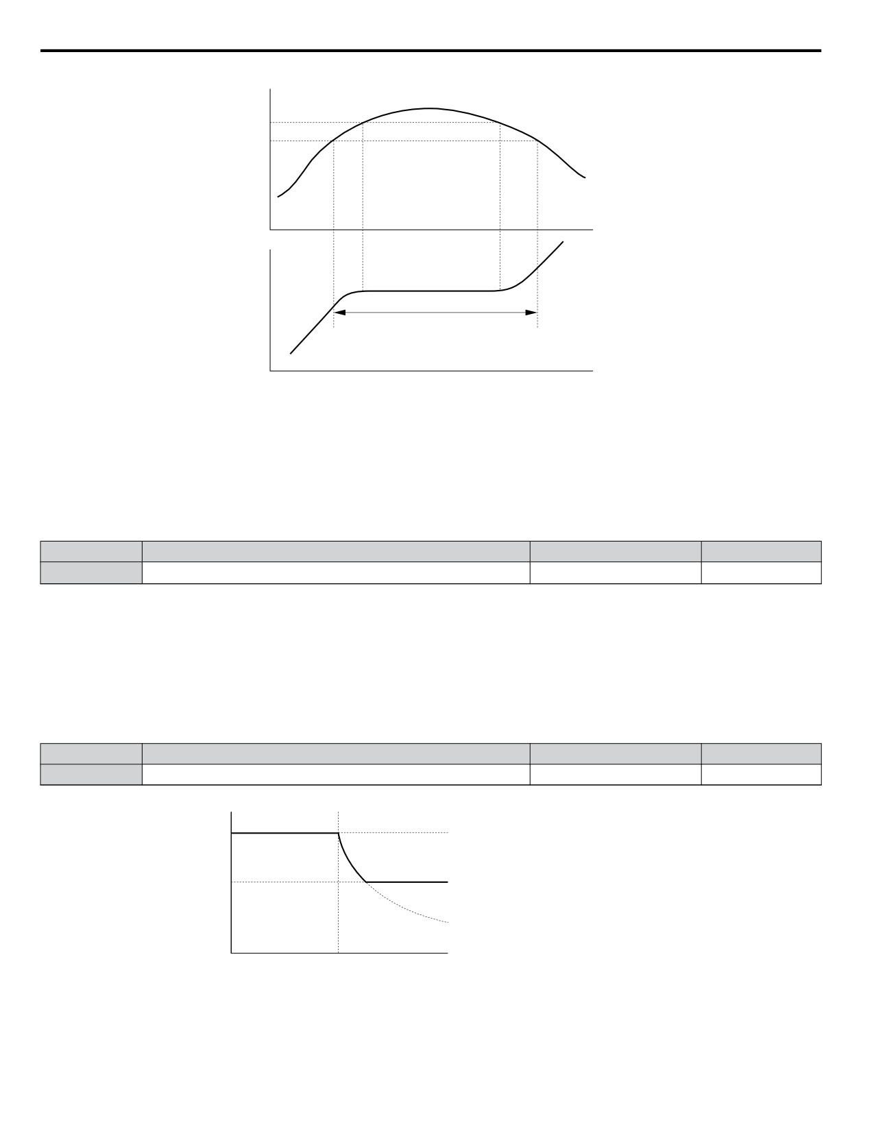
5.8 L: Protection Functions
Output current
Stall Prevention Level
During Acceleration
L3-02
L3-02
-15%
Time
Output frequency
Controls the output frequency
to prevent the motor from stalling
Time
Figure 5.72 Stall Prevention During Acceleration for Induction Motors
Setting 2: Intelligent Stall Prevention
When L3-01 = 2, the drive will disregard the selected acceleration time and try to accelerate in the minimum time. The
acceleration rate is adjusted so that the current does not exceed the value set in parameter L3-02.
n L3-02: Stall Prevention Level During Acceleration
Sets the output current level at which the Stall Prevention during acceleration is activated.
No.
Name
Setting Range
Default
<1>
L3-02
Stall Prevention Level during Acceleration
0 to 150% <1>
<1> Upper limit and default value are dependent on parameter L8-38, Frequency Reduction Selection
• If stalling occurs with L3-02 set to its default value when using a motor that is relatively small compared to the drive, try
lowering L3-02.
• When operating the motor in the constant power range, also set parameter L3-03.
n L3-03: Stall Prevention Limit During Acceleration
The Stall Prevention level is automatically reduced when the motor is operated in the constant power range. L3-03 sets the
lower limit for this reduction as a percentage of the drive rated current.
No.
Name
Setting Range
Default
L3-03
Stall Prevention Limit during Acceleration
0 to 100%
50%
Stall Prevention level during Acceleration
L3-02
L3-03
Output frequency
E1-06
Base frequency
Figure 5.73 Stall Prevention Level and Limit During Acceleration
198
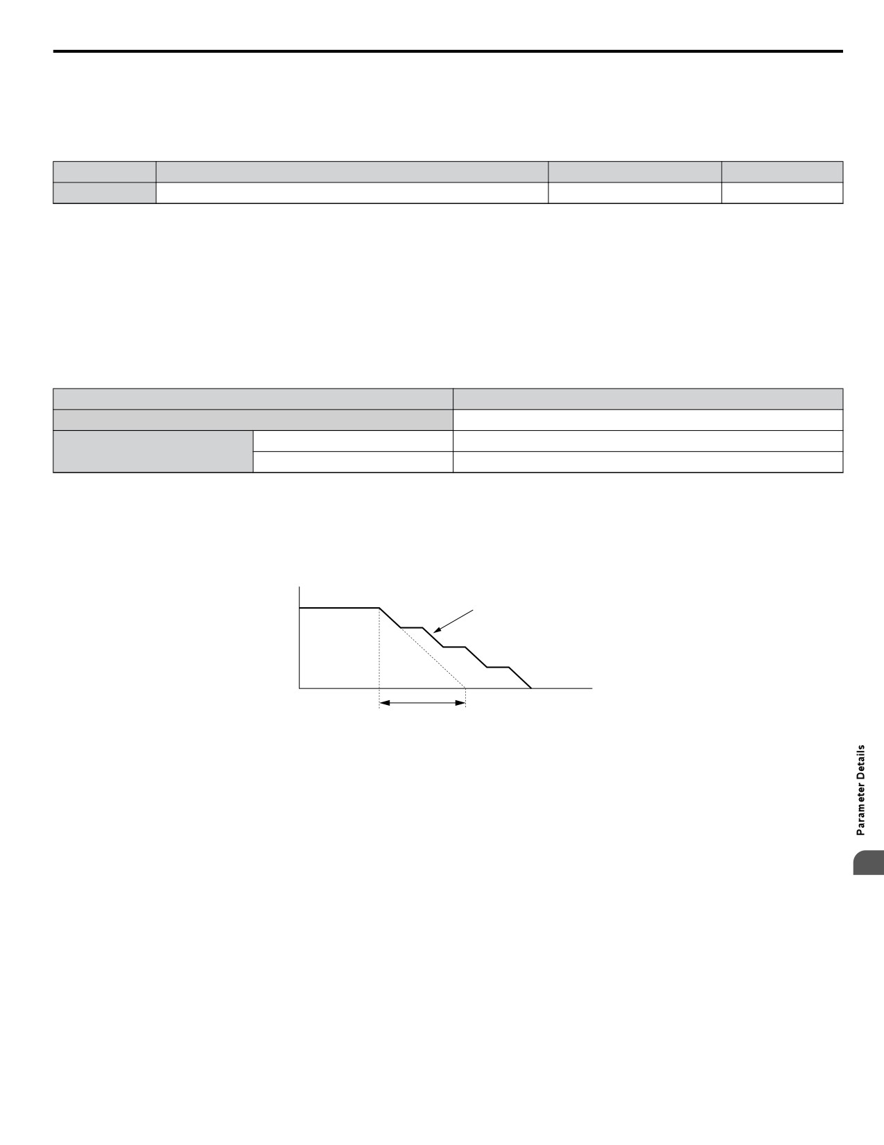
5.8 L: Protection Functions
n L3-04: Stall Prevention Selection during Deceleration
Stall Prevention during deceleration can control the deceleration based on the DC bus voltage and prevent an overvoltage fault
caused by high inertia or rapid deceleration.
Selects the Stall Prevention method during deceleration.
No.
Name
Setting Range
Default
L3-04
Stall Prevention Selection During Deceleration Selection
0 to 4; 7
0
Setting 0: Disabled
When this setting is used, the drive decelerates according to the set deceleration time. With high inertia loads or rapid
deceleration, an overvoltage (ov) fault may occur. In this case use braking options or switch to another L3-04 selection.
Note:
Use this setting or set L3-04 to 3 whenever a Dynamic Braking Resistor or another braking option is used.
Setting 1: General Purpose Stall Prevention
With this setting the drive tries to decelerate in the set deceleration time. When the DC bus voltage exceeds the Stall Prevention
level, the drive pauses deceleration. Deceleration continues as soon as the DC bus voltage drops below that level. Stall
Prevention may be triggered repeatedly to avoid an overvoltage fault. The DC bus voltage level for Stall Prevention depends
on the input voltage setting E1-01.
Drive Input Voltage
Stall Prevention Level during Deceleration
200 V Class
Vdc = 380 V
E1-01 ≥ 400 V
Vdc = 760 V
400 V Class
E1-01 < 400 V
Vdc = 660 V
Note:
1. This setting should not be used in combination with a Dynamic Braking Resistor or other braking options. If Stall Prevention during
deceleration is enabled, it will be triggered before the braking resistor option can operate.
2. This method may lengthen the total deceleration time compared to the set value. If this is not appropriate for the application consider
using a braking option.
Figure 5.74 illustrates the function of Stall Prevention during deceleration.
Output Frequency
Deceleration characteristics
when Stall Prevention was
triggered during deceleration
Time
specified deceleration time
Figure 5.74 Stall Prevention During Deceleration
Setting 2: Intelligent Stall Prevention
With this setting the drive adjusts the deceleration rate so that the DC bus voltage is kept at the level set in parameter L3-17.
This way the shortest possible deceleration time is achieved while the motor is protected from stalling. The deceleration time
that has been selected is disregarded, but the achievable deceleration time cannot be smaller than 1/10 of the set deceleration
time.
5
This function uses the following parameters for adjusting the deceleration rate:
• DC bus voltage gain L3-20
• Deceleration rate calculations gain L3-21
• Inertia calculations for motor acceleration time L3-24
• Load inertia ratio L3-25
Refer to these parameter descriptions for details.
Note:
As the deceleration time is not constant, Intelligent Stall Prevention should not be used in applications where stopping accuracy is a concern.
Use braking options instead.
Setting 3: Stall Prevention with Braking Option
Enables the Stall Prevention function while using a braking resistor. Use this setting if overvoltage occurs with L3-04 disabled
when using a braking resistor. This makes it possible to reduce the deceleration time.
199
5.8 L: Protection Functions
Setting 4: Overexcitation Deceleration
Enables overexcitation deceleration. Overexcitation Deceleration (increasing the motor flux) shortens the deceleration time
compared to deceleration with no Stall Prevention (L3-04 = 0). Repetitive or long overexcitation deceleration can result in
motor overheat. In such situations, either shorten the deceleration time setting or use a braking resistor option.
Use parameters n3-13 and n3-23 for fine-tuning this function.
Note:
Because the allowable flux level for overexcitation varies based on the flux saturation characteristics of the motor, set the proper
overexcitation level by adjusting the excitation gain in parameter n3-13. Motor characteristics and inertia of the machine influence the
deceleration time during overexcitation deceleration.
Setting 7: Overexcitation Deceleration 3
Provides faster deceleration than normal Overexcitation Deceleration (L3-04 = 4) by increasing the amount of overexcitation
current applied to the motor.
Note:
When operation permits, use normal Overexcitation Deceleration (L3-04 = 4).
n L3-05: Stall Prevention Selection During Run
Stall Prevention During Run can prevent a motor from stalling by automatically reducing the speed when a transient overload
occurs while the motor is running at constant speed.
This parameter selects the Stall Prevention During Run method.
No.
Name
Setting Range
Default
L3-05
Stall Prevention Selection During Run
0 to 2
1
Note:
When output frequency is 6 Hz or less, Stall Prevention During Run is disabled regardless of the setting in L3-05/06.
Setting 0: Disabled
Drive runs at the set frequency reference. A heavy load may cause the motor to stall and trip the drive with an oC or oL fault.
Setting 1: Decelerate Using C1-02
If the current exceeds the Stall Prevention level set in parameter L3-06, the drive decelerates at Decel Time 1 (C1-02). Once
the current level drops below the value of L3-06 minus 2% for 100 ms it accelerates back to the frequency reference at the
active acceleration time.
Setting 2: Decelerate Using C1-04
Same as setting 1 except the drive decelerates at decel time 2 (C1-04).
n L3-06: Stall Prevention Level During Run
Sets the current level for Stall Prevention During Run. Depending on the setting of parameter L3-23 the level is automatically
reduced in the constant power range (speed beyond base speed).
No.
Name
Setting Range
Default
<1>
L3-06
Stall Prevention Level During Run
30 to 150 <1>
<1> Upper limit and default value are dependent on parameter L8-38, Frequency Reduction Selection
n L3-11: Overvoltage Suppression Function Selection
Enables or disables the overvoltage suppression function.
No.
Name
Setting Range
Default
L3-11
ov Suppression Function Selection
0 or 1
0
Setting 0: Disabled
The output frequency is not adjusted. A regenerative load may trip the drive with an overvoltage fault. Use this setting if
braking options are installed.
Setting 1: Enabled
When the DC bus voltage rises due to regenerative load, an overvoltage fault is prevented by increasing the output frequency.
n L3-17: Target DC Bus Voltage for Overvoltage Suppression and Stall Prevention
Sets the target DC bus voltage target level used by the overvoltage suppression function (L3-11 = 1) and Intelligent Stall
Prevention during deceleration (L3-04 = 2).
200