Yaskawa iQpump Micro AC Drive Compact Intelligent Pump Controller. User Manual (2014) - page 3
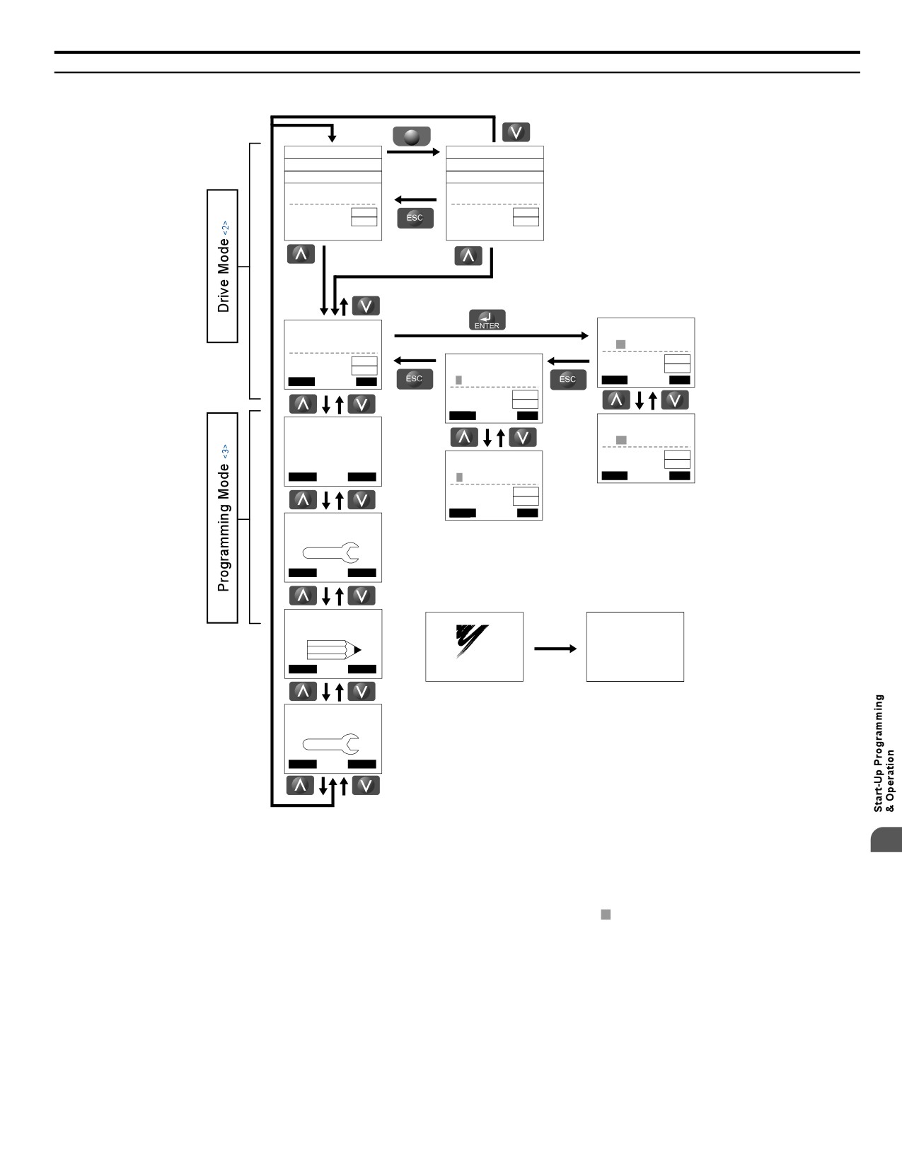
4.6 Using the Optional HOA Keypad
u Menu Structure for HOA Keypad
F1
QMONI: Use F1/F2
QMONI: Use F1/F2
MENU: Use UP/DWN
<1>
MENU: Use UP/DWN
- MODE -
DRV Rdy
- MODE -
DRV Rdy
Auto Setpoint
ANF Timer
U5-99= 0.0PSI
U1-99= 0.0sec
U1-02= 0.00Hz
LSEQ
U1-02= 0.00Hz
LSEQ
U1-91= 0.0PSI
LREF
U1-91= 0.0PSI
LREF
<-MONITOR->
<-MONITOR->
- MODE -
DRV Rdy
-MONITR-
DRV Rdy
Monitor Menu
Frequency Ref
U1-01= 0.00Hz
U1-01=0.00Hz
U1-02= 0.00Hz
LSEQ
-MONITR-
DRV
Rdy
U1-02= 0.00Hz
LSEQ
U1-91= 0.0PSI
LREF
Monitor
U1-91= 0.0PSI
LREF
Home
FWD
U1
-01= 0.00Hz
Home FWD
U1-02= 0.00Hz
LSEQ
U1-91= 0.0PSI
LREF
H
ome
FWD
-MONITR-
DRV Rdy
- MODE - PRG RDY
Output Freq
Modified Consts
U1-02= 0.00Hz
<4>
Appl (001)
U1-02= 0.00Hz
LSEQ
-MONITR-
DRV Rdy
Std (029)
U1-91= 0.0PSI
LREF
Fault Trace
Home
FWD
DATA
U2 -01= -----
Home
FWD
U2-02= oPr
LSEQ
U2-03= 0.00Hz
LREF
H
ome
FWD
- MODE -
PRG
Pump Quick Setup
Home
FWD
Initial Display <5>
- MODE -
PRG
Programming
XXXV, XXXHP
XXXA
iQpump
<XXXXXXXXX>
YASKAWA
CIMR-PWXXXXXXXX
Home
FWD
<6>
- MODE - PRG
Auto-Tuning
AUTO
Home FWD
Figure 4.9 HOA Keypad Menu and Screen Structure
4
<1> The display cycles between these three displays on the initial startup screen and the Quick Monitor screens.
<2> Pressing “AUTO” or “HAND” will start the motor.
<3> Drive cannot operate motor.
<4> Flashing characters are shown with white letters on gray background. (Example: 0 )
<5> The Frequency Reference appears after the initial display that shows the product name.
<6> The information that appears on the display will vary depending on the drive model.
81
4.6 Using the Optional HOA Keypad
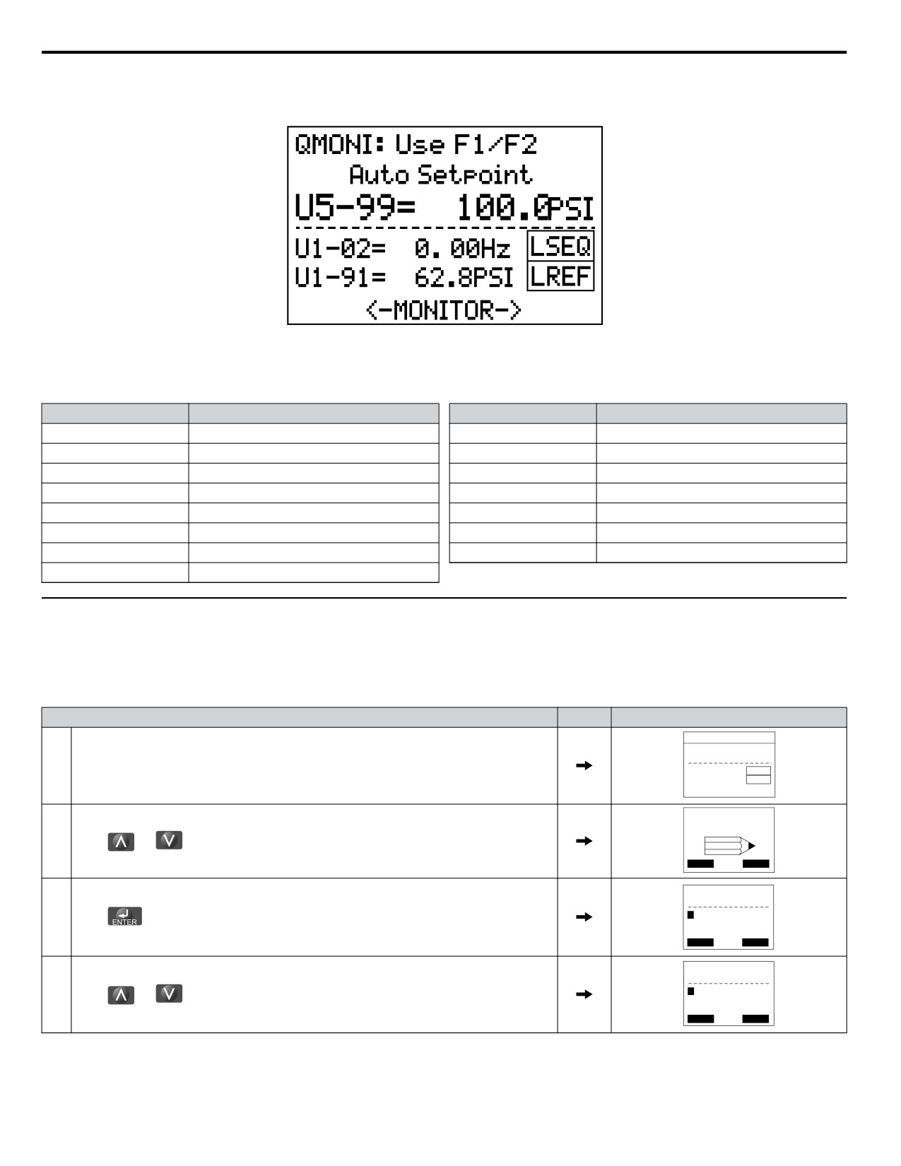
n Home Quick Monitor Display (Optional HOA Keypad)
The Home Quick Monitor provides an easily accessible preset group of monitors that are frequently used during operation.
Figure 4.10 Home Quick Monitor Screen
The following monitors are available via the Quick Monitor:
Monitor
Name
Monitor
Name
U1-01
Frequency Reference
U1-11
Output Terminal Status
U5-99
Auto Setpoint
U1-13
Terminal A1 Level
U1-02
Output Frequency
U1-14
Terminal A2 Level
U1-03
Output Current
U1-25
CPU 1 SW Number
U1-06
Output Voltage
U4-01
Drive Elapsed Time
U1-07
DC Bus Voltage
U9-02
iQ Network Activity
U1-08
Output Power
U1-99
Anti-No-Flow Timer
U1-10
Input Terminal Status
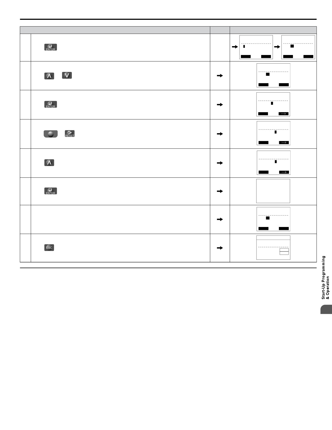
u Changing Parameter Settings or Values
This example explains changing C1-02 (Deceleration Time 1) from 10.0 seconds (default) to 20.0 seconds.
Note:
During serial communication writing, if a parameter change is also attempted via the HOA keypad, a “BUSY - WRITE PROTECTED”
message will display. Parameter change will not be possible from the HOA keypad until an Enter command is received via the serial
communication to finish the serial writing process.
Step
Display/Result
- MODE -
DRV Rdy
Auto Setpoint
U5-99= 0.0PSI
1.
Turn on the power to the drive. The initial display appears.
U1-02= 0.00Hz
LSEQ
U1-91= 0.0PSI
LREF
<-MONITOR->
- MODE -
PRG
Programming
2.
Press
or
until the Parameter Setting Mode screen appears.
Home
FWD
-PRMSET-
PRG
Initialization
3.
A1-00=
0
Press
to enter the parameter menu tree.
Select Language
Home
FWD
DATA
-PRMSET-
PRG
Basic Setup
C1-01=
20.0 sec
4.
Press
or
to select the C parameter group.
Accel Time 1
Home
FWD
DATA
82
4.6
Using the Optional HOA Keypad
Step
Display/Result
-PRMSET- PRG
-PRMSET- PRG
el Time 1
5.
Press
two times.
-PRMSET-
PRG
Decel Time 1
C1-02=
10.0sec
6.
(0.0~6000.0)
Press
or
to select parameter C1-02.
“10.0 sec”
Home FWD DATA
-PRMSET-
PRG
Decel Time 1
C1-02= 0010.0sec
7.
Press
to view the current setting value (10.0 s). The leftmost digit flashes.
(0.0~6000.0)
“10.0 sec”
Home
FWD
-PRMSET-
PRG
Decel Time 1
C1-02=0010.0sec
8.
F2
(0.0~6000.0)
Press
or
until the desired number is selected. “1” flashes.
“10.0 sec”
Home
FWD
-PRMSET-
PRG
Decel Time 1
C1-02=0020.0sec
9.
Press
and enter 0020.0.
(0.0~6000.0)
“10.0 sec”
Home
FWD
10.
Press
to confirm the change.
Entry Accepted
-PRMSET-
PRG
Decel Time 1
C1-02=
20.0sec
11.
The display automatically returns to the screen shown in Step 6.
(0.0~6000.0)
“10.0 sec”
Home FWD DATA
- MODE -
DRV Rdy
Auto Setpoint
U5-99= 0.0PSI
12.
U1-02= 0.00Hz
Press
as many times as necessary to return to the initial display.
LSEQ
U1-91= 0.0PSI
LREF
<-MONITOR->
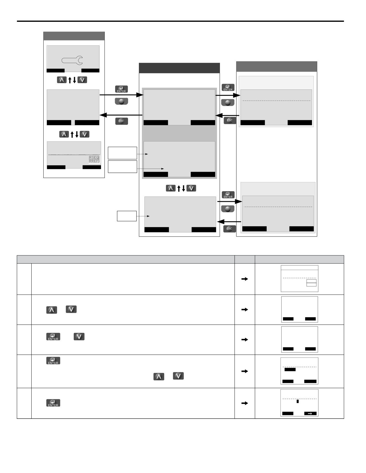
u Verifying Parameter Changes: Modified Constants Menu
The Modified Constants Menu lists parameter changes as a result of using an Application Preset (A1-03) or by making manual
parameter changes (including Auto-Tuning). The Application Preset changes are contained in the (Appl) folder while all other
changes appear in the (Std) folder. The Modified Constants Menu helps determine which settings have been changed, and is
particularly useful when replacing a drive. If no settings have been changed in either folder, the Modified Constants folders
will read “None Modified”. The Modified Constants Menu also allows users to quickly access and re-edit any parameter
4
settings that have been changed.
Note:
The Modified Constants Menu will not display parameters from the A1 group (except for A1-02) or E5-01 even if those parameters have
been changed from their default settings.
The following example details where the drive was initialized to Pump Down Mode (A1-03 = 6009) and then three additional
parameters were changed including the deceleration time. The example shows how to then change the deceleration time from
14.0 s to 24 seconds.
83
4.6
Using the Optional HOA Keypad
Main Menu
- MODE -
PRG
Pump Quick Setup
Modified Type Selection
Parameter View
Home
FWD
Parameter changed after
Initializing using A1-03
-MODE-
PRG RDY
- MODE -
PRG RDY
-VERIFY-
PRG
Modified Consts
Output Level Sel
Modified Consts
F2
F2
Appl (005)
>> Appl (005)
<<
b5-09=
1
*1*
Std (003)
Inverse Acting
Std (003)
Home
DATA
Home
DATA
Home
(idle)
- MODE -
DRV RDY
- MODE -
PRG RDY
Monitor Menu
Double arrows
Modified Consts
U1-01=
14.00 Hz
indicate selection
>> Appl (005)
<<
U1-02=
0.00Hz
U1-03=
0.00A
Information about
Std (003)
Home
FWD
the selection is
--changes after
scrolled
Home
DATA
Parameter changed from
factory default setting
- MODE -
PRG RDY
-VERIFY-
PRG
Modified Consts
Ref Source 1
F2
Appl (005)
b1-01=
1
*1*
Std is now
selected
>> Std (003)
<<
Analog Input
Home
DATA
Home
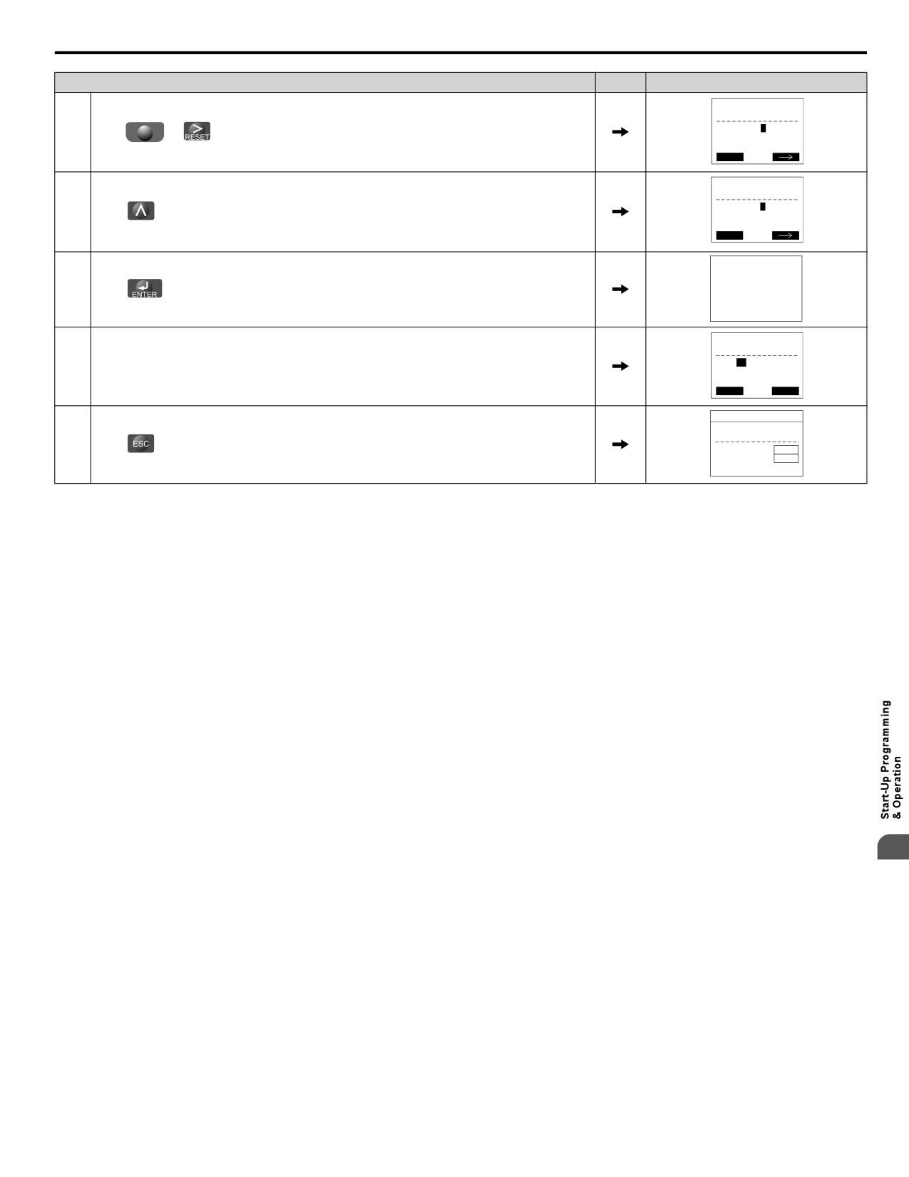
Steps to change parameter C1-02, Deceleration Time, from 14.0 to 24.0 seconds:
Step
Display/Result
- MODE -
DRV Rdy
Auto Setpoint
U5-99= 0.0PSI
1.
Turn on the power to the drive. The initial display appears.
U1-02= 0.00Hz
LSEQ
U1-91= 0.0PSI
LREF
<-MONITOR->
- MODE - PRG RDY
Modified Consts
2.
Appl (005)
Press
or
until the display shows the top of the Modified Constants Menu.
Std (003)
Home FWD DATA
- MODE -
PRG
Modified Consts
3.
Press
then
to select standard (Std) parameters that have been edited from their
Appl (005)
>> Std (003) <<
original default settings.
Home FWD DATA
- VERIFY - PRG Rdy
Press
to enter the list of standard parameters that have been edited from their original
Accel Time 1
default settings.
C1-02
= 14.0sec
4.
(0.0~6000.0)
“10.0sec”
If parameters other than C1-02 have been changed, use
or
to scroll until C1-02
Home
FWD
appears.
- VERIFY - PRG
Rdy
Accel Time 1
C1-01=0014.0sec
5.
Press
to access the setting value. Left digit flashes.
(0.0~6000.0)
“10.0sec”
Home
FWD
84
4.6 Using the Optional HOA Keypad
Step
Display/Result
-PRMSET-
PRG
Decel Time 1
C1-02=0014.0sec
6.
Press F2
or
until the desired number is selected. “1” flashes.
(0.0~6000.0)
“10.0 sec”
Home
FWD
-PRMSET-
PRG
Decel Time 1
C1-02=0024.0sec
7.
Press
and enter 0024.0.
(0.0~6000.0)
“10.0 sec”
Home
FWD
8.
Press
to confirm the change.
Entry Accepted
-PRMSET-
PRG
Decel Time 1
C1-02=
24.0sec
9.
The display automatically returns to the screen shown in Step 4.
(0.0~6000.0)
“10.0 sec”
Home FWD DATA
- MODE -
DRV Rdy
Auto Setpoint
U5-99= 0.0PSI
10.
Press
as many times as necessary to return to the initial display.
U1-02= 0.00Hz
LSEQ
U1-91= 0.0PSI
LREF
<-MONITOR->
4
85
4.7 Pump Application Presets
4.7
Pump Application Presets
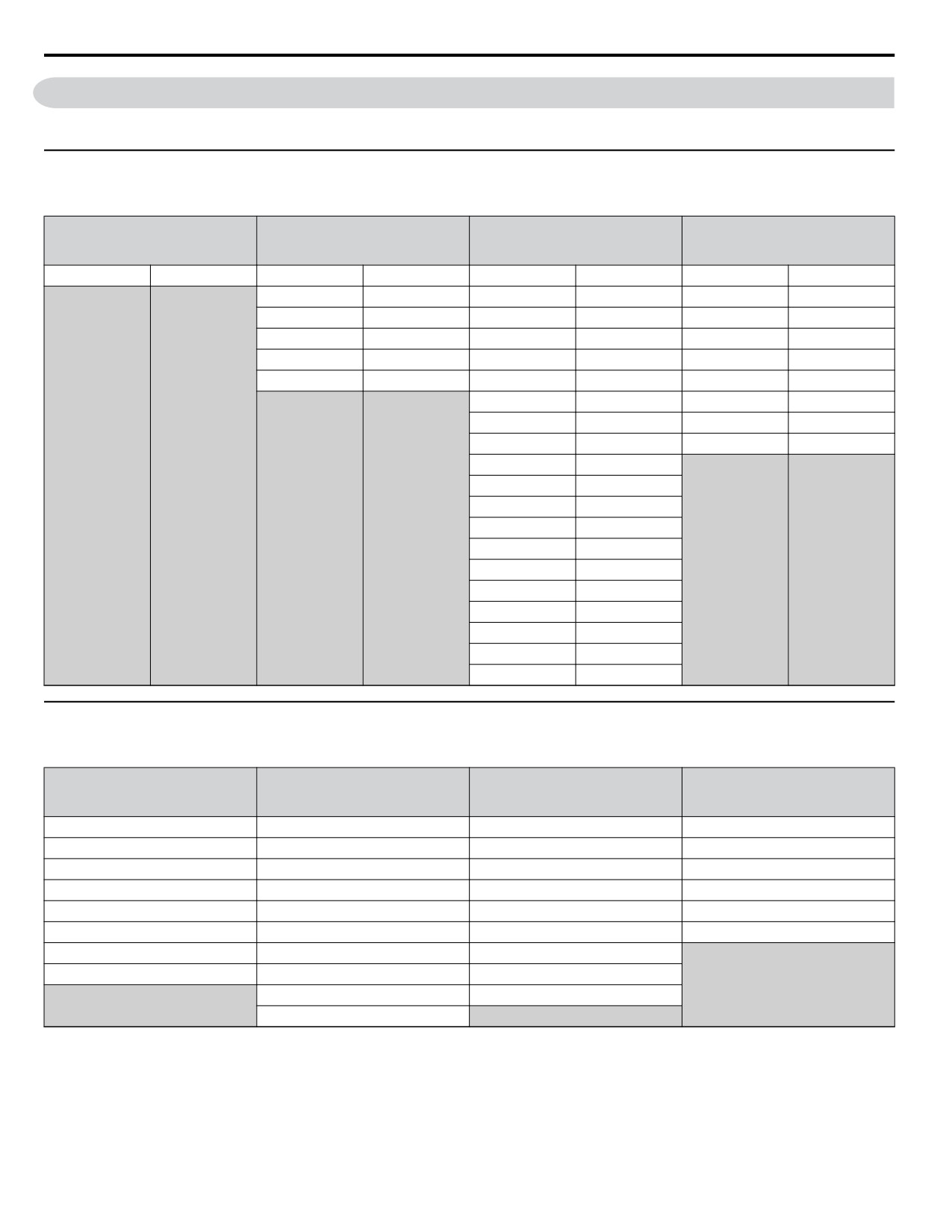
The following sections list the parameters affected by the different Application Presets.
u Parameters Set Depending on A1-03 Setting
The following table shows the parameters that are set depending on the A1-03 initialization:
A1-03 = 6008
A1-03 = 6009
A1-03 = 7770
A1-03 = 7771
(A1-06 = 8)
(A1-06 = 9)
(A1-06 = 1)
(A1-06 = 2)
Pressure Control
Pump Down Level
General Purpose
Sub Mtr GP Oper
Parameter
Value
Parameter
Value
Parameter
Value
Parameter
Value
b5-09
1
b1-01
1
b5-01
0
b5-39
2
b1-02
1
H1-06
4
P1-02
6
b5-01
0
H1-07
0
P2-01
2
C1-01
25.0 sec
H2-02
0
P2-23
0.00%
C1-02
25.0 sec
H2-03
A
H1-06
4
o1-06
0
H1-07
F
P1-05
0 sec
H2-02
0
d1-01
40.00 Hz
H2-03
A
H3-02
0
H3-10
2
L5-01
0
L5-04
180.0 sec
o1-06
0
P1-05
0 sec
P1-06
0.0 Hz
P4-12
0.0 Hz
P4-17
0.0 min
P5-02
0.0 Hz
u Parameters Displayed Depending on A1-06 Setting
The following table shows which parameters are shown on the Pump Quick Setup menu depending on the A1-06 selection:
A1-03 = 6008
A1-03 = 6009
A1-03 = 7770
A1-03 = 7771
(A1-06 = 8)
(A1-06 = 9)
(A1-06 = 1)
(A1-06 = 2)
Pressure Control
Pump Down Level
General Purpose
Sub Mtr GP Oper
E2-01
E2-01
b1-01
E2-01
E2-04
E2-04
b1-02
E2-04
P1-03
P1-02
C1-01
d1-01
Q1-01
P1-03
C1-02
P1-06
P1-04
Q1-01
E2-01
P4-10
P1-06
P1-04
E2-04
P5-04
P4-10
P1-06
L5-01
P5-04
P2-02
L5-04
P4-10
P1-06
P5-04
86
4.8 iQpump Presets and Functions
4.8
iQpump Presets and Functions
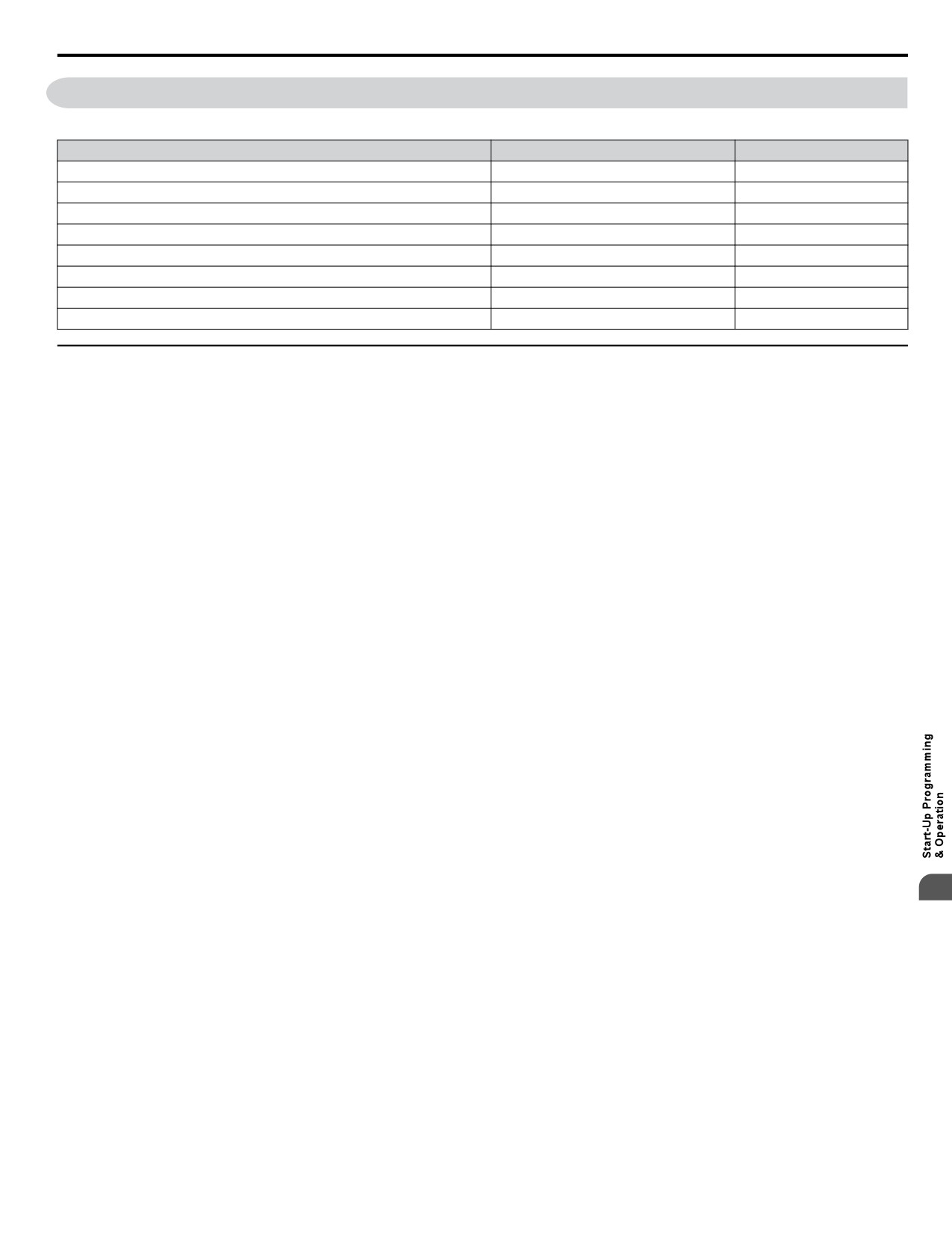
Table 4.8 iQpump Presets and Functions
Feature Name
Preset or Function
Page
Pump Down Level Control
Preset
87
General Purpose Mode
Preset
89
Low City or Low Suction Inlet Pressure
Function
90
Current Limit
Function
91
Speed Follower Deceleration Time Switchover
Function
92
Software (MEMOBUS) Multiplexing Setup
Function
93
Simple Duplex System Application
Function
97
Multiplexing Stop History
Function
100
u iQpump Presets
n Pump Down Level Control Application Preset
This preset allows the drive to regulate the depth of water in a tank or other vessel that is being filled by an external source.
A feedback device that measures water depth is wired to the drive. A PI-control process loop will then modulate the pump
speed to pump water out the tank to keep the water depth the setpoint level (pump out at the recharge rate). The drive controller
has an application preset to simplify the start up and control of this application.
• System units are in feet (P1-02 = 6).
• Feedback device scaling (P1-03). The feedback device scaling must be entered into the drive for proper control.
• Minimum pump speed (P1-06). Most pumps cannot be run below a certain speed or cavitation can occur.
• Number of Motor Poles (E2-04). The default is for a 2-pole motor.
• Sleep Function. The drive controller will sleep when the system demand is low and awaken when demand returns.
Required Control Wiring
Most depth level transducers have current-based feedback (4-20 mA). The A2 terminal of the drive is preset for 4-20 mA and
pre-programmed for PID feedback (H3-10 = B).
Start Up Procedure
1. Set parameter A1-03 to 6009 (Pump Down Level) to pre-set parameter values for this application.
2. Set the motor-rated current in parameter E2-01. This information can be found on the motor nameplate or specification
sheet.
3. Set the number of motor poles in parameter E2-04 (2-pole motors have a rated RPM of slightly less than 3600 RPM;
4-pole motors have a rated RPM of slightly less than 1800 RPM). This information can be found on the motor
nameplate or specification sheet.
4. Set the feedback device scaling in parameter P1-03. Check the sensor nameplate or specification sheet. For example,
if the device outputs 20 mA at 14.50 ft of water depth, the set P1-03 to 14.50. The drive controller will automatically
scale all associated parameters and monitors. Monitor U1-91 (Pump Feedback) will display the measured water depth
in feet. The drive has a High Feedback Fault set in parameter P1-11. Make sure that P1-11 is appropriately set for
sensor scaling in P1-03.
4
5. Set the desired water depth level in parameter Q1-01 (PID setpoint). This is desired water depth that the drive will
regulate the pump speed around. To quickly access this parameter, press the HOME key and then the ENTER key.
The U1-99 monitor on the home screen displays the Q1-01 PID setpoint.
6. Set the minimum speed that the pump can be run in parameter P1-06. The default is 40 Hz. This information can be
found on the pump specification sheet.
7. The default setting does not allow the drive to automatically restart after power loss if the drive was running at the
time of power loss. Set P4-10, AUTO Mode Operator Run Power Down Storage, to 1 to enable this feature.
8. Press the AUTO key to start the drive with PID control (water depth control). Press the OFF key to stop the drive.
9. The pump can be run in HAND (LOCAL) mode for maintenance purposes by pressing the HAND key while the drive
is stopped. The HAND key acts as a start button. Press the OFF button to stop the drive. Press AUTO to return the
drive to PID control. The HAND speed reference can be set in P5-02 (Hand Reference 1). Disable the HAND key by
setting P5-04 to 0 (disabled).
10.Configure the sleep function. The pump can be programmed to shut off or “sleep” if the water falls below the depth
set in parameter P2-02 (Sleep Level). The controller will monitor the water depth feedback signal and wake up when
the water depth rises above the setting in parameter P1-04 (Start/Draw Down Level). Logically, set the Sleep Level
87
4.8 iQpump Presets and Functions
(P2-02) lower than the PID setpoint and set the Draw Down Level (P1-04) slightly above the PID setpoint to prevent
the drive from waking up until the water exceeds the desired depth setting. Sleeping helps the drive save energy and
mechanical wear. When P1-04 is set to 0 (default), the sleep function is disabled.
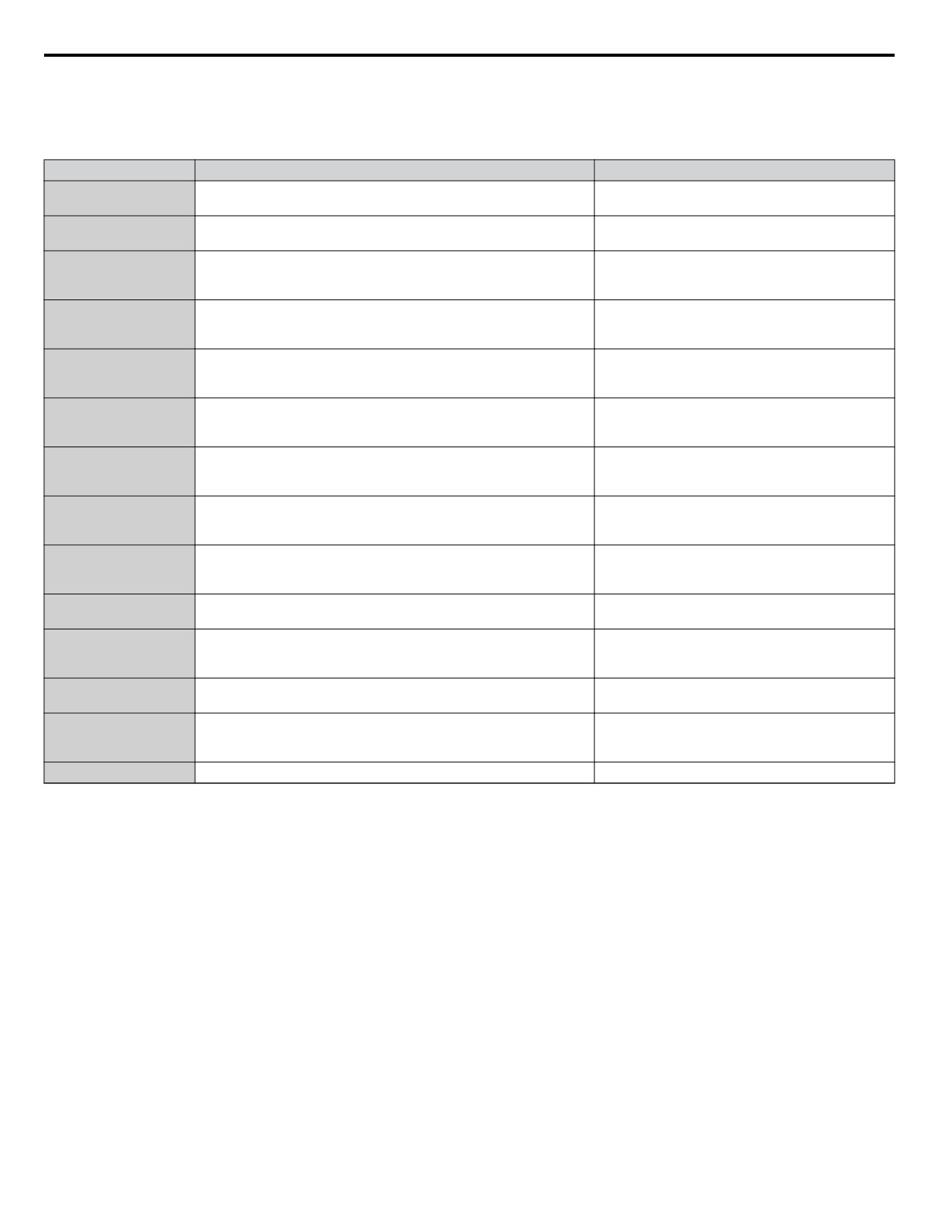
Related Parameters
No.
Parameter Name
Setting Values
Default: 2
A1-01
Access Level Selection
Range: 0 to 3
Default: 0
A1-03
Initialize Parameters
Range: 0 to 5550; 6008, 6009, 7770, 7771
Default: Depends on o2-04
E2-01
Motor Rated Current
Min.: 10% of drive rated current
Max.: 200% of drive rated current
Default: 2
E2-04
Number of Motor Poles
Min.: 2
Max.: 48
Default: 145.0 PSI
P1-03
Feedback Device Scaling
Min.: 0.1
Max.: 6000.0
Default: 155.0 PSI
P1-11
High Feedback Level
Min.: 0.0
Max.: 6000.0
Default: 40.0 Hz
P1-06
Minimum Pump Speed
Min.: 0.0
Max.: [E1-04]
Default: 0.0 PSI
P1-04
Start / Draw Down Level
Min.: -999.9
Max.: 999.9
Default: 0.0 Hz
P2-02
Sleep Level
Min.: 0.0
Max.: 6000.0
Default: 0
P4-10
AUTO Mode Operator Run Power Down Storage
Range: 0, 1
Default: 40.0 Hz
P5-02
HAND Speed Reference 1
Min.: 0
Max.: [E1-04]
Default: 1
P5-04
HAND Key Function Selection
Range: 0, 1
Default: 0.0
Q1-01
PID Controller Setpoint 1
Min.: 0.0
Max.: 6000.0
U1-99
Anti-No-Flow Timer
No signal output available
88
4.8 iQpump Presets and Functions
n General Purpose Mode Application Preset
The purpose of this mode is to allow the drive controller to run a motor at a set speed without the PID process loop. This preset
is designed to simplify using the drive for applications other than pumping control. The default settings call for the frequency
reference to be an analog input and the run command to come from the terminal strip via a maintain contact closure. The PID
loop is disabled and no process feedback is required.
Required Control Wiring
No additional control wiring is required when the drive controller is at its default settings.
Start Up Procedure
1. Set parameter A1-03 to 7770 (General Purpose Mode) to pre-set parameter values for this application.
2. Set the source of the frequency reference for the drive controller in parameter b1-01. The default setting is from the
terminal strip via a 0 to 10 V analog signal wired into terminal A1.
3. Set the source of the Run Command for the drive controller in parameter b1-02. The default setting is from the terminal
strip via a maintained contact closure.
4. Set the Acceleration Time of the motor in parameter C1-01. This is the time to accelerate the motor from zero speed
to 60 Hz (E1-04, Maximum Output Frequency).
5. Determine the stopping method of the motor. The default setting is coast to stop. To ramp the motor to a stop, set
b1-03 to 0 and then set the motor deceleration time in parameter C1-02. This is the time to stop the motor from to 60
Hz (E1-04, Maximum Output Frequency) to zero speed.
6. Set the motor-rated current in parameter E2-01. This information can be found on the motor nameplate or specification
sheet.
7. Set the number of motor poles in parameter E2-04 (2-pole motors have a rated RPM of slightly less than 3600 RPM;
4-pole motors have a rated RPM of slightly less than 1800 RPM). This information can be found on the motor
nameplate or specification sheet.
8. Determine whether the drive controller should attempt to reset itself after a fault. The default setting is disabled. The
function is turned on by setting 1 to 10 reset attempts in parameter L5-01 and the time between each reset in parameter
L5-04.
9. Set the minimum speed at which the motor can run in parameter P1-06. If the system has a minimum safe operation
speed, set it in P1-06. This will act as a lower limit of the frequency reference.
10.The motor can be run in HAND (LOCAL) Mode for maintenance purposes by pressing the HAND key while the drive
is stopped. The HAND key acts as a start button. Press the OFF button to stop the drive. Set P5-04 to 0 to disable
the HAND key. The default frequency reference is 0.0 Hz in HAND Mode. This can be changed in parameter P5-02.
The AUTO key has no effect with the default settings in the General Purpose Application Preset.
Related Parameters
No.
Parameter Name
Setting Values
Default: 0
A1-03
Initialize Parameters
Range: 0 to 5550; 6008, 6009, 7770, 7771
Default: 0
b1-01
Frequency Reference Selection 1
Range: 0 to 4
Default: 0
b1-02
Run Command Selection 1
Range: 0 to 3
Default: 1
b1-03
Stopping Method Selection
Range: 0 to 3
4
Default: 20.0 s
C1-01
Acceleration Time 1
Min.: 0.0
Max.: 6000.0
Default: 10.0 s
C1-02
Deceleration Time 1
Min.: 0.0
Max.: 6000.0
Default: 60.0 Hz
E1-04
Maximum Output Frequency
Min.: 40.0
Max.: 400.0
Default: Depends on o2-04
E2-01
Motor Rated Current
Min.: 10% of drive rated current
Max.: 200% of drive rated current
Default: 2
E2-04
Number of Motor Poles
Min.: 2
Max.: 48
89
4.8 iQpump Presets and Functions
No.
Parameter Name
Setting Values
Default: 5
L5-01
Number of Auto Restart Attempts
Min.: 0
Max.: 10
Default: 20.0 s
L5-04
Fault Reset Interval Time
Min.: 10.0
Max.: 3600.0
Default: 40.0 Hz
P1-06
Minimum Pump Speed
Min.: 0.0
Max.: [E1-04]
Default: 40.0 Hz
P5-02
HAND Reference
Min.: 0
Max.: [E1-04]
Default: 1
P5-04
HAND Key Function Selection
Range: 0, 1
u iQpump Functions
n Low City or Low Suction Inlet Pressure
This function is used with low suction inlet pressure switches on pressure booster systems for buildings that get their main
water supply from a municipality. This pressure switch enables and disables the pump system when the inlet supply is at a
low demand and when running the pump system in this condition will cause damage.
An inlet pressure switch is wired directly into the drive using one of the digital input terminals. If the pressure switch is active
and sufficient pressure is available, the drive system will operate normally. If the pressure switch indicates that incoming
pressure is too low, the drive will take the following actions:
• The drive will be forced into a sleep-like state (coast to stop).
• Any drives staged in multiplex mode will immediately coast to stop.
• The selected alarm “Low City Pressure”, “Low Suction Pressure”, or “Low Water In Tank” will be displayed (determined
by P4-24).
All drives will restart when sufficient pressure returns.
Required Control Wiring
Any one of the multi-function digital inputs (S1 to S7) must be wired and programmed with a low suction inlet pressure switch.
The appropriate terminal parameter (H1-oo) must be to set 73 (Low City Pressure). The action of the switch (normally open /
normally closed) is set in parameter P4-21.
Start Up Procedure
1. Set all other parameters required for the application such as PID control loop, sleep, motor, and I/O parameters.
2. Set one digital input for the low suction inlet pressure switch (H1-oo = 73). Wire the switch to this terminal.
3. Configure the terminal for a normally open / closed switch type using parameter P4-21.
4. Configure the delay times for activating and removing the alarm in parameters P4-23 and P4-24. This can be used to
stop the drive from frequent cycling when pressure varies greatly.
5. Select the alarm message that will be displayed when a Low City condition is detected using parameter P4-24. Options
include “Low Cty Pressure”, “Low Suction Pres”, and “Low Watr In Tank”.
Related Parameters, Faults, and Alarms
No.
Parameter Name
Setting Values
Default: 1
P4-21
Low City Input Select
Range: 0, 1
Default: 10 s
P4-22
Low City On-Delay Time
Min.: 1
Max.: 1000
Default: 5 s
P4-23
Low City Off-Delay Time
Min.: 0
Max.: 1000
Default: 0
P4-24
Low City Alarm Text
Range: 0 to 2
90
4.8 iQpump Presets and Functions
H1 Multi-Function Digital Input Settings
H1-oo
Function
Description
Setting
Indicates that sufficient or insufficient pressure is present on the inlet to the pump. Used mainly for pressure
73
Low City Press
booster situations.
Digital Operator Display
Minor Fault Name
Low City Pressure
Low City Pressure
(LCP)
Cause
Possible Solution
Insufficient pressure is present on the inlet
to the pump.
• Check pressure switch contact for correct operation.
Shown when P4-24 = 0 and when the digital
• Check control wiring to drive terminal strip from pressure switch contact.
input has been active (closed for P4-21 = 0,
or open for P4-21 = 1) for the time set in
• Check to make sure that suction pressure is present by means of a separate measuring device.
P4-22.
Digital Operator Display
Minor Fault Name
Low Suction Pressure
Low Suction Pressure
(LSP)
Cause
Possible Solution
Shown when P4-24 = 1 and when the digital input has been active (closed for P4-21 = 0, or open for P4-21
= 1) for the time set in P4-22.
Insufficient suction pressure is present.
The drive, if running, coasts-to-stop and does not run until the digital input has been inactive for the time
set in P4-22.
Digital Operator Display
Minor Fault Name
Low Water in Tank
Low Water in Tank
(LWT)
Cause
Possible Solution
The water level in the tank is too low.
• Check pressure switch contact for correct operation.
Shown when P4-24 = 2 and when the digital
• Check control wiring to drive terminal strip from pressure switch contact.
input has been active (closed for P4-21 = 0,
• Check to make sure that suction pressure is present by means of a separate measuring device.
or open for P4-21 = 1) for the time set in
P4-22.
• Raise the water level.
n Current Limit
This function provides a current limit of the pump (motor). The function is designed to prevent long-term overload conditions
of the pump, especially if the motor and drive are oversized compared to the pump. The drive will attempt to limit the output
current by reducing the frequency reference. The frequency is reduced using an internal current PID regulator. When the
Current Limit function is active, the alarm "Current Limit Foldback" or “CUr” will be displayed on the digital operator keypad.
This function will only operate correctly when the drive is connected to a variable torque motor load such as a centrifugal
pump. More specifically, it will only operate if the load is such that output current increases as output frequency increases
(and vice-versa). The current limit function reduces the pump speed to just above the lower value between the minimum pump
speed (P1-06) or the minimum output frequency. If PID mode is enabled (b5-01 > 0), a special limit will be applied to the PID
integrator when output current limit is active to prevent integrator wind-up.
Current Limit Foldback
4
(CUr)
Start Up Procedure
1. Set all other parameters required for the application such as PID control loop, sleep, motor, and I/O parameters
2. Turn on the current limit function by setting Q3-01 to 1 (enabled). The default setting is 0 (disabled).
3. Set the desired current limit in Q3-02. This value should not exceed the motor, pump or drive ratings. This does not
change the motor (oL1) or drive (oL2) overload functions.
4. If desired, program a multi-function digital output (H2-oo) to 89 (Output Current Limit) to annunciate the alarm.
Related Parameters
No.
Parameter Name
Setting Values
Default: 0
Q3-01
Output Current Limit Select
Range: 0, 1
Default: 0.0 A
Q3-02
Current Limit
Min.: 0.0
Max.: 1000.0
91
4.8 iQpump Presets and Functions
H2 Multi-Function Digital Output Settings
H2-oo
Function
Description
Setting
Closed: Drive output speed is being limited due to the output current limit or the single phase foldback
89
Output I Limit
regulator.
The drive displays a message on the keypad when the drive is in output current limit.
Digital Operator Display
Message
Current Limit Foldback
Displayed when drive output speed is being limited due to the output current limit. Reduce the load or replace with
(CUr)
higher capacity drive.
n Speed Follower Deceleration Time Switchover
The iQpump Speed Follower will attempt to match the speed of the Lead Drive after the Lag Drive Fixed Speed Delay.
Consider a scenario wherein the system needs help from an idle drive to maintain system pressure. When the idle drive is
called to run, the difference between the setpoint and the feedback may be too small to make the drive accelerate faster. In
such cases, the system is configured with these settings:
• Set for Lag Drive Speed Follower
• Add Pump method is Frequency Reference
• Frequency Reference setting close to the maximum frequency
The system will drop the speed after the Lag Drive Fixed Speed Delay expires in order to follow the output frequency of the
previously idle drive. This transition may cause unwanted pressure drops. A longer deceleration time will be activated on the
lag drives when the system switches the drive that is being followed. The longer deceleration time will be effective for a
programmable setting, after which the regular deceleration time is used.
Functional Operation
If P9-05 = 3 (Follow Lead Spd), the lag drive will use the network information and the lead drive output speed as its frequency
reference. The lag drive final speed reference is affected by (Lag Follower Gain, P9-30) and then by (Lag Follower Bias,
P9-31).
Lag Drive Speed = ( Lead Drive Speed x Lag Follower Gain ) + Lag Follower Bias
When P9-33 > 0.0 sec, an alternate deceleration time (Lag Follower Decel, P9-32) is used when the drive switches from the
latched speed (Lag Fixed Delay, P9-07) to the new Lead drive output frequency. The deceleration time is active for the duration
set in P9-33, Lag Follower Deceleration Time Active Time, and will switch back to the regular deceleration rate when it
expires.
Note:
Parameter functionality stated below only applies when P1-01 = 3 (MEMOBUS Network)
Related Parameters
No.
Name
Description
Values
Determines the functionality of the lag drives.
0: Fixed speed. The drive runs at the P9-06 setting after the time set in P9-07
expires.
Default: 0
P9-05
Lag Drive Mode
2: Turn off. The drive stops running when it switches to a lag drive after the time
Range: 0, 2, 3
set in P9-07 expires.
3: Follow Lead Speed. The drive will follow the speed of the current lead drive,
applying P9-30 gain and P9-31 bias.
Specifies how long speed is latched before performing the function specified in
Default: 5 s
P9-07
Lag Fixed Speed Delay
P9-05 when the drive changes from a lead to a lag.
Min.: 0
Max.: 1000
Sets the gain to be applied to the speed of the current lead drive when P9-05 is set
Default: 100.0%
P9-30
Lag Drive Speed Follower Gain
to 3. The bias to be applied is set in P9-31.
Min.: 0.0
Max.: 300.0
Sets the bias to be applied to the speed of the current lead drive when P9-05 is set
Default: 0.00 Hz
P9-31
Lag Drive Speed Follower Bias
to 3. The gain to be applied is set in P9-30.
Min.: -60.0
Max.: 60.0
Sets the deceleration time when the P9-33 timer is running and the drive is running
Default: 60.0 s
Lag Follower Deceleration
P9-32
as Lag Drive Speed Follower (P9-05 is set to 3).
Min.: 0.0
Time
Max.: 1000.0
Sets the time during which the deceleration time set in P9-32 is effective. The drive
Default: 0.0 s
Lag Follower Deceleration
P9-33
will use the standard deceleration rate when it expires.
Min.: 0.0
Time Active Time
Setting this parameter to 0.0 disables the function.
Max.: 360.0
92
4.8 iQpump Presets and Functions
No.
Name
Description
Values
Determines the communication compatibility for the iQPump MEMOBUS
network.
Network Compatibility
Default: 2
P9-99
0: A-Ver: 30034
Selection
Range: 0 to 2
1: B-Ver: 30035/36
2: iQ Smart Network
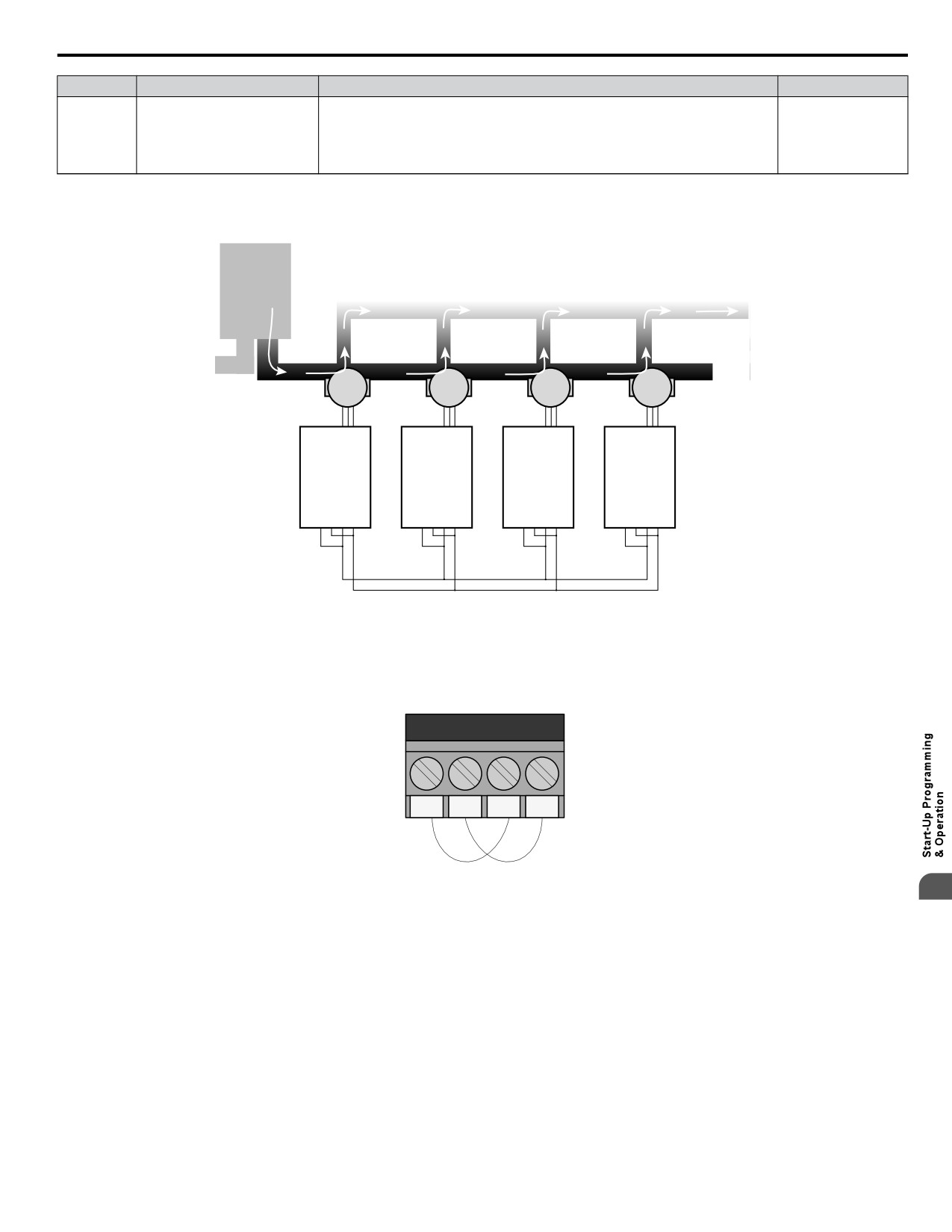
n Software (MEMOBUS) Multiplexing Setup
Wiring the Drive RS-485 Network Connections
Reservoir
Process Supply
Pump
Pump
Pump
Pump
iQpump
iQpump
iQpump
iQpump
R+ R- S+ S-
R+ R- S+ S-
R+ R- S+ S-
R+ R- S+ S-
RS-485 Network
Figure 4.11 System Overview
Perform the following steps to make the RS-485 network connections between all drives that will be multiplexed:
1. Jumper terminals (R+ to S+) and jumper terminals (R- to S-) terminals on each individual drive according to Figure
4.12.
Drive X
R+
R-
S+
S-
Figure 4.12 Drive Terminal Jumpers
4
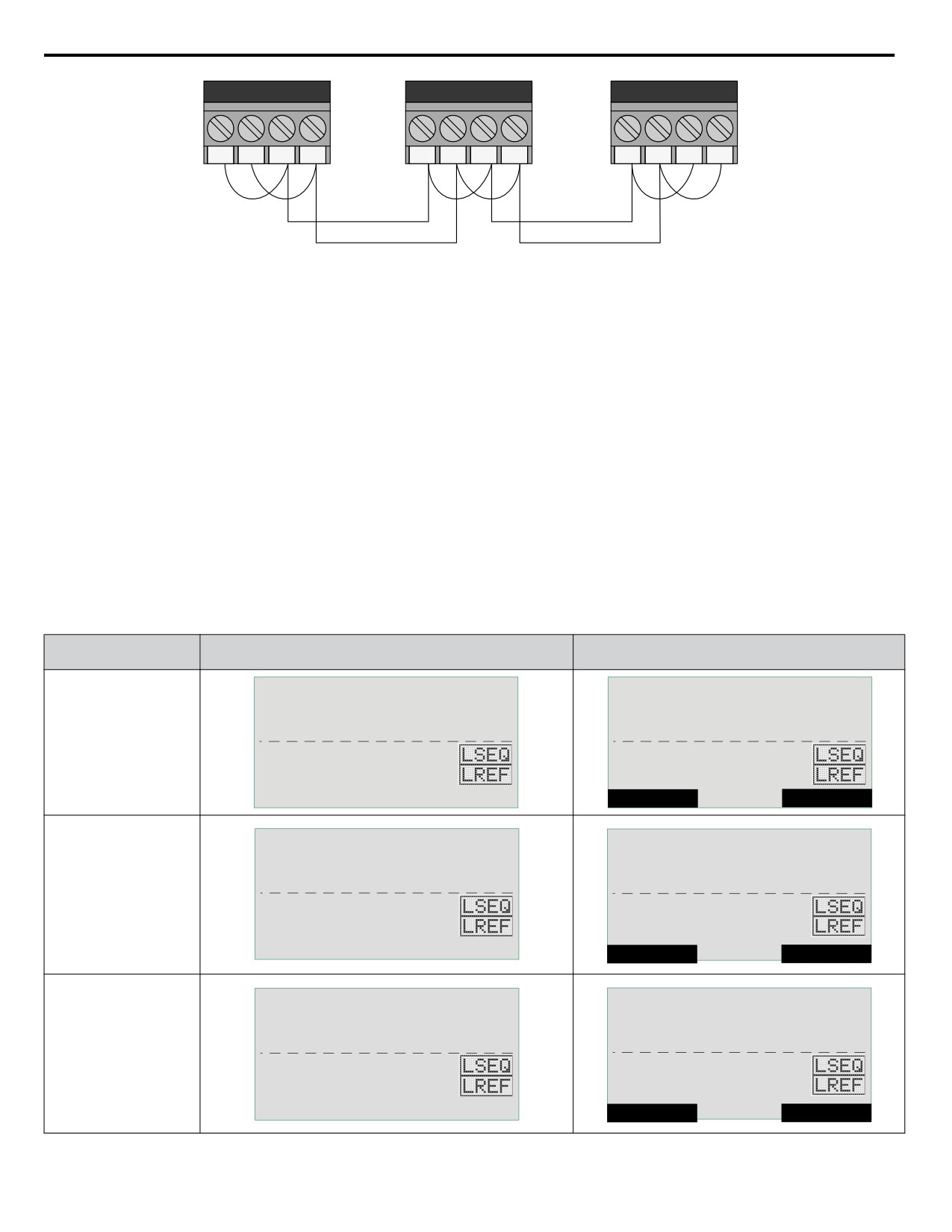
2. Use shielded communication cable for steps 3 and 4 to connect the drives in a daisy chain manner according to
Figure 4.13.
3. Daisy chain the (R+ to S+) terminals between each drive.
4. Daisy chain the (R- to S-) terminals between each drive.
93
4.8 iQpump Presets and Functions
Drive 1
Drive 2
Drive 3
R+
R-
S+
S-
R+
R-
S+
S-
R+
R-
S+
S-
Figure 4.13 Daisy Chain Three Drives
Setting the Drive Networking Parameters
1.
1. Set parameter H5-01, Serial Node Address, on each drive.
Note:
For optimal performance, use consecutive numbers starting from 1. Parameter setting H5-01 must be unique for each drive.
2. Set parameter P9-25, Highest Node Address, on each drive.
Note:
For optimal performance, set to highest H5-01 value. This setting must be the same for all the drives on the network.
3. Set P1-01 to 3 (MEMOBUS/Modbus Network) on all the drives.
4. Cycle main power to all networked drives.
Note:
The H5-01 setting will not take effect until power is cycled to the drive and may cause communication errors and unexpected
behavior.
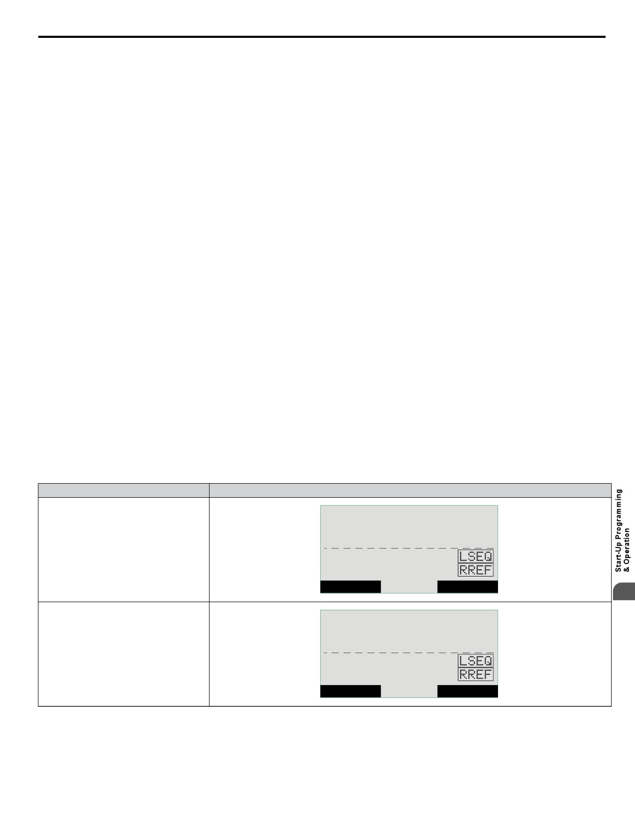
Verifying Drive Network Communications
Access monitor U9-02, Network Activity, and verify:
• No drives have a value of 0 <->
• All drives are receiving valid data indicated by a regular change in the monitor value.
• At least one drive has the unit <M>, while the others have the unit <+>.
Table 4.9 Network Connectivity Information
Top Line on Home Screen
Network State
U9-02 Network Activity
(o1-12 = 1)
<M> CONNECTED
- MONITR -
DRV RDY
Pump Off Network
Network Activity
Drive is the Master and is
U5-99=
100.0PSI
U9-02=
9453<M>
communicating with
another drive.
U1-02=
0.00Hz
U1-02=
0.00Hz
U1-91=
62.8PSI
U1-91=
62.8PSI
<- MONITOR - >
Home
FWD
<+> CONNECTED
- MONITR -
DRV RDY
Pump Off Network
Network Activity
Drive is a node on the
network and is
U5-99=
100.0PSI
U9-02=
324<+>
communicating with a
U1-02=
0.00Hz
U1-02=
0.00Hz
Master.
U1-91=
62.8PSI
U1-91=
62.8PSI
<- MONITOR - >
Home
FWD
<-> DISCONNECTED
- MONITR -
DRV RDY
Pump Off Network
Network Activity
Drive is not able to
U5-99=
100.0PSI
U9-02=
0<->
communicate to any other
drives.
U1-02=
0.00Hz
U1-02=
0.00Hz
U1-91=
62.8PSI
U1-91=
62.8PSI
<- MONITOR - >
Home
FWD
If a drive displays U9-02 = 0 <->:
94
4.8 iQpump Presets and Functions
• Check physical connections.
• Verify the H5-oo serial communication settings.
• Confirm the P9-25 and P9-27 settings on all the drives. P9-25 should be set to the highest H5-01 address and at least one
drive should have P9-27 set to 0.
• Cycle main power.
Multiplexing Principle
Always observed by system:
• New drives start as Lead and run in PID mode.
• Only the Lead drive can request staging and de-staging.
• Staging will start a new Lead drive and make the old Lead drive into a Lag drive.
• De-staging will stop the current Lead drive and restore the previous drive as the Lead drive.
Multiplexing Messages
During multiplexing, the drive will display a message when it will be staged in or de-staged out. The message will indicate if
it is being staged in or out and display a countdown timer of how long until the change takes place.
One of the following conditions must be met for de-staging to occur:
• High Feedback Quick De-stage
• Low Feedback Quick De-stage
• Normal De-stage
• Low Water Level De-stage
• Suction Pressure De-stage
Drive Run Order
U9-04, Running Queue No:
• Shows the position in the iQpump MEMOBUS running queue.
• U9-04 = 0 for pumps that are not running.
• U9-04 = 1 on the first pump that came on and is still running.
• U9-04 = 2 on the second pump that came on and is still running.
• U9-04 = the number of pumps running for the current Lead drive.
Multiplex Status Display
Table 4.10 Multiplex Status Display (Optional HOA Keypad, JVOP-183)
Network State
Display
- MODE -
DRV RDY
Pump Off Network
Drive is not able to accept commands from
U5-99= 100.0PSI
the iQpump MEMOBUS network because
the drive is not in AUTO Mode run.
U1-02=
0.00Hz
U1-91=
62.8PSI
Home
4
- MODE -
DRV RDY
Wait for Net Cmd
Drive is in AUTO Mode and waiting for a run
U5-99= 100.0PSI
command from the iQpump MEMOBUS
network.
U1-02=
0.00Hz
U1-91=
62.8PSI
Home
95
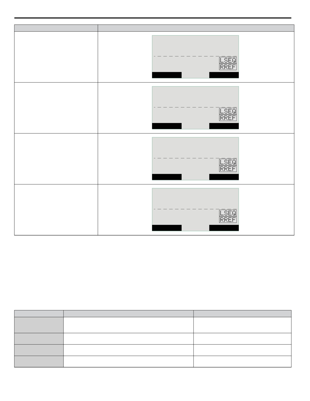
4.8 iQpump Presets and Functions
Network State
Display
- MODE -
DRV RDY
Lead: Setpoint
Drive is in AUTO Mode, Lead operation and
U5-99= 100.0PSI
is currently regulating the system using PID
control.
U1-02=
52.38Hz
U1-91=
62.8PSI
Home
- MODE -
DRV RDY
Lag: Fixed Hold
Drive is in AUTO Mode, Lag operation and
is holding the speed at the time it made the
U1-01= 59.41HZ
switch from being a lead drive to a lag. Speed
is held until P9-07 time expires. The Home
U1-02=
59.41Hz
screen will display U1-01 instead of U5-99.
U1-91=
99.8PSI
Home
- MODE -
DRV RDY
Lag: Fixed P9-06
Drive is in AUTO Mode, Lag operation and
U1-01= 55.00HZ
is running at the speed set in P9-06. The
Home Screen will display U1-01 instead of
U1-02=
55.00Hz
U5-99.
U1-91=
99.9PSI
Home
- MODE -
DRV RDY
Lag: Follow Lead
Drive is in AUTO Mode, Lag operation and
U1-01= 51.37HZ
is following the speed of the current Lead
drive. The Home screen will display U1-01
U1-02=
51.35Hz
instead of U5-99.
U1-91=
98.9PSI
Home
PID Feedback via Network
The Network PID Feedback comes from a drive on the network with a valid analog PID feedback source and can be used as
the primary or secondary feedback source for a networked drive.
Set P9-02 to 0 if a drive has an analog PID feedback device installed and switching to network as a backup is not desired.
If a drive has an analog PID feedback device installed and the network PID feedback is considered as a backup, set P9-02 to
1 for no alarm message when switched and set P9-02 to 2 for an alarm.
Set P9-02 to 3 if a drive has no analog PID feedback device installed and relies solely on the analog PID feedback of another
networked drive.
Note:
Connect an analog PID feedback device to each drive for best performance.
Related Parameters
No.
Parameter Name
Setting Values
Default: 1F (Hex)
H5-01
Drive Node Address
Min.: 0
Max.: FF
Default: 0
P1-01
Pump Mode
Range: 0, 3
Default: 0
P9-02
Feedback Source
Range: 0 to 3
Default: 4
P9-25
Highest Node Address
Range: 2 to 4
96
4.8 iQpump Presets and Functions
No.
Parameter Name
Setting Values
Default: 0
P9-27
Network Recovery
Range: 0 to 3
U9-02
Network Activity
No signal output available
U9-04
Running Queue Number
No signal output available
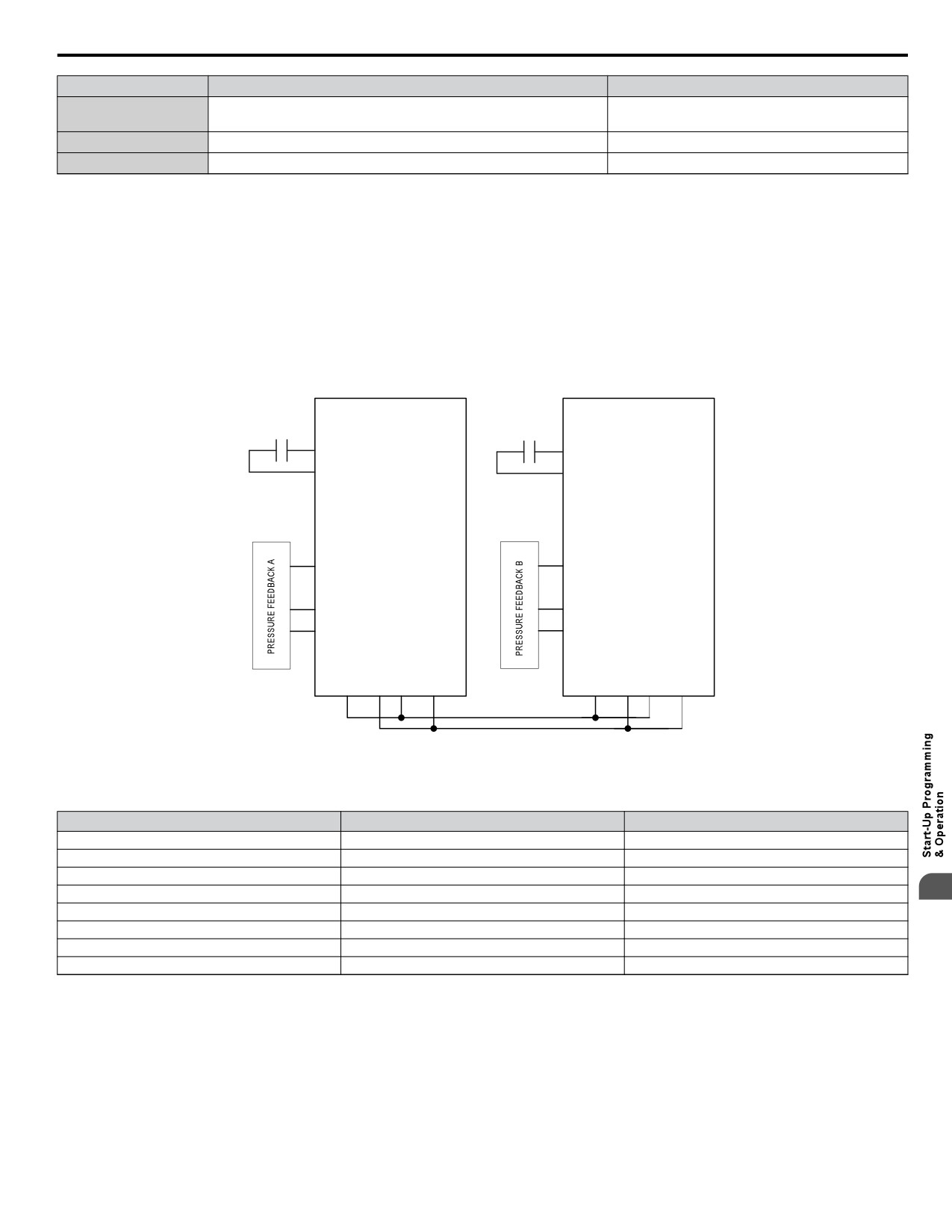
n Simple Duplex System Application Example
A customer requires a duplex system with the following capabilities:
• Control the system pressure using two drives (no PLCs).
• Alternate drives everyday to even out the pump wear.
• Toggle switch for Run command.
• Each drive will have its own feedback transducer. Due to the shut-off valves, the network feedback should not be used as a
backup.
• Pump is at optimal running speed when at fixed speed of 54.0 Hz.
• Setpoint is 100 PSI, feedback scale is 145 PSI, start level is 80 PSI.
RUN
RUN
S1
S1
SN
SN
Drive B
Drive A
15 HP
15 HP
+V
+V
A1
A1
A2
A2
AC
AC
R+
R-
S+
S-
R+
R-
S+
S-
Figure 4.14 Simplified Wiring Diagram
Table 4.11 Related Parameters for Simple Duplex System Example
Description
Drive A <1>
Drive B <1>
Run Source: 1 (Terminals)
b1-02 = 1
b1-02 = 1
Node Address
H5-01 = 1
H5-01 = 2
Highest Node Address
P9-25 = 2
P9-25 = 2
Pump Mode: 3 (Network)
P1-01 = 3
P1-01 = 3
4
Feedback Source: 0 (Analog)
P9-02 = 0
P9-02 = 0
Lag Fixed Speed
P9-06 = 54.0 Hz
P9-06 = 54.0 Hz
Setpoint
U5-99 = 100 PSI
U5-99 = 100 PSI
Start Level
P1-04 = 80 PSI
P1-04 = 80 PSI
<1> All other multiplexing and alternation parameters are set to default settings.
Duplex System with Fine Tuning Application Example
The customer would like to solve a pump cycling problem. Currently the second drive runs for 10 to 20 seconds at minimum
speed then shuts off, letting the first drive run at maximum. This will then run the second drive again and the cycle will repeat.
The customer must also account for system losses when running both pumps by boosting the setpoint by 5 PSI. In the event
that the pressure exceeds 125 PSI, the second drive should de-stage if both drives are running. If the pressure exceeds 140
PSI, a high feedback fault should occur and stop the drive.
There are multiple methods to handle the pump cycling problem:
• Lower the lag fixed speed (P9-06)
97
4.8 iQpump Presets and Functions
• Decrease the lag fixed speed delay (P9-07)
• Increase the staging frequency level (P9-09)
• Increase the staging delay time (P9-11)
• Increase the de-staging delay time (P9-15)
• Increase the stabilization time (P9-16)
• Increase both the Add Freq Level and Add Dly Time
Table 4.12 Related Parameters for Duplex System with Fine Tuning Application Example
Description
Drive A <1>
Drive B <1>
Run Source: 1 (Terminals)
b1-02 = 1
b1-02 = 1
Node Address
H5-01 = 1
H5-01 = 2
Highest Node Address
P9-25 = 2
P9-25 = 2
Pump Mode: 3 (Network)
P1-01 = 3
P1-01 = 3
Feedback Source: 0 (Analog)
P9-02 = 0
P9-02 = 0
Lag Fixed Speed
P9-06 = 54.0 Hz
P9-06 = 54.0 Hz
Setpoint
U5-99 = 100 PSI
U5-99 = 100 PSI
Start Level
P1-04 = 140 PSI
P1-04 = 140 PSI
High Feedback Quick De-Stage
P9-18 = 89.3%
P9-18 = 89.3%
Setpoint Modifier
P9-17 = 5.0 PSI
P9-17 = 5.0 PSI
Add Drive Frequency Level
P9-09 = 59.0 Hz
P9-09 = 59.0 Hz
Add Drive Delay
P9-11 = 12.0 s
P9-11 = 12.0 s
<1> All other multiplexing and alternation parameters are set to default settings.
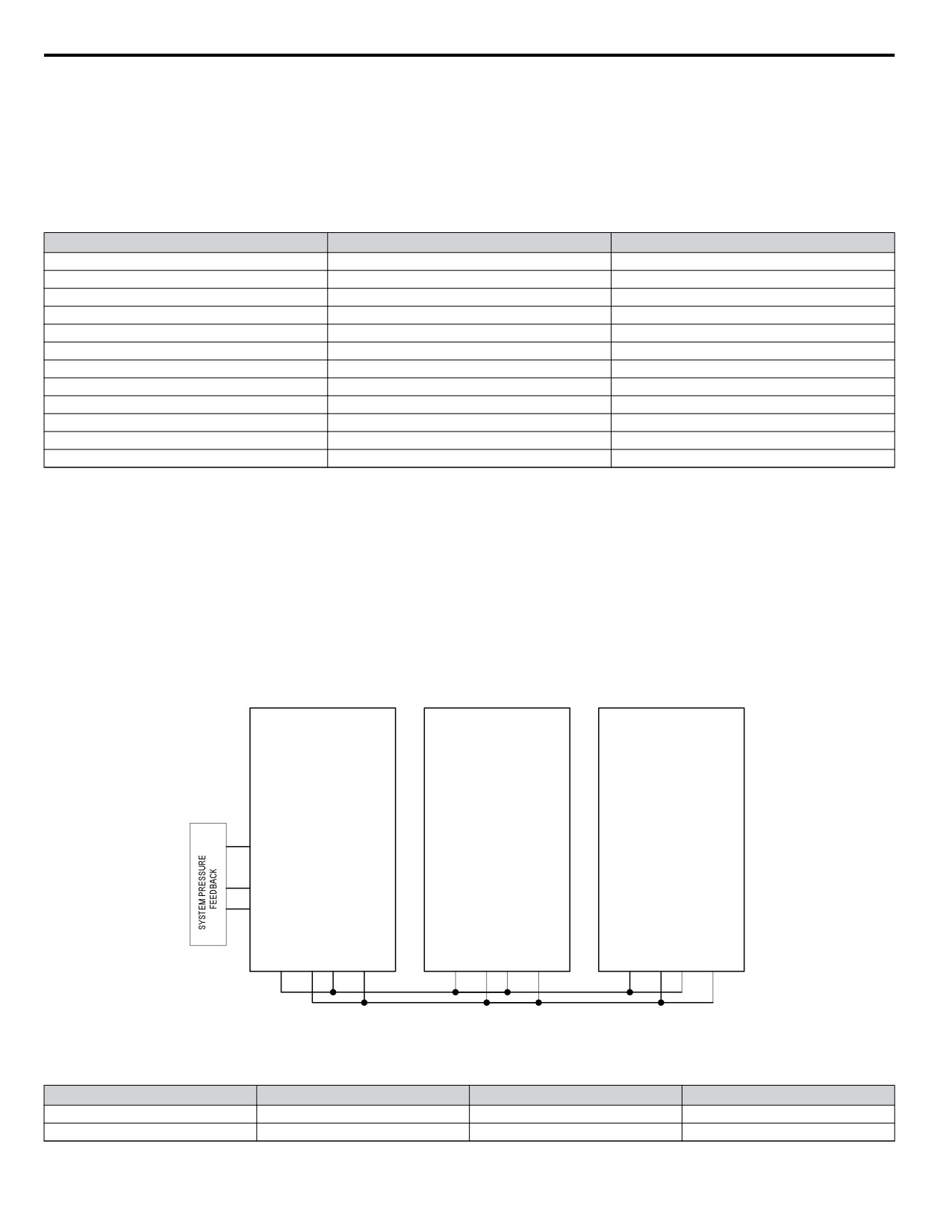
Duplex System with Jockey Pump Example
A customer requires a pump system with the following requirements:
• One small pump (the Jockey pump) will run the system during off-peak times.
• Two larger pumps will run the system when the demand is higher.
• The Jockey pump should not run when the two larger pumps are running.
• Pump wear is still an issue, but it is expected that the small pump will run longer hours and will always run first after a loss
of power.
• The feedback scale is 145 PSI.
• There is only one feedback transducer in the system.
S1
S1
S1
SN
SN
SN
(Jockey Pump)
Drive B
Drive C
10 HP
15 HP
15 HP
+V
+V
+V
A1
A1
A1
A2
A2
A2
AC
AC
AC
R+
R-
S+
S-
R+
R-
S+
S-
R+
R-
S+
S-
Figure 4.15 Simplified Wiring Diagram
Table 4.13 Related Parameters for Duplex System with Jockey Pump Example
Description
Jockey Pump <1>
Drive B <1>
Drive C <1>
Node Address
H5-01 = 1
H5-01 = 2
H5-01 = 3
Highest Node Address
P9-25 = 3
P9-25 = 3
P9-25 = 3
98
4.8 iQpump Presets and Functions
Description
Jockey Pump <1>
Drive B <1>
Drive C <1>
Pump Mode: 3 (Network)
P1-01 = 3
P1-01 = 3
P1-01 = 3
Feedback Source: 0 (Analog), 3
P9-02 = 0
P9-02 = 3
P9-02 = 3
(Network)
Lag Drive Speed: 0 (Always), 2
P9-05 = 2
P9-05 = 0
P9-05 = 0
(Turn Off)
Allow Net Run: 0 (Always), 2 (First
P9-20 = 2
P9-20 = 0
P9-20 = 0
Only)
Run Priority
P9-21 = 7
P9-21 = 8
P9-21 = 8
Lead Swap @ Sleep
P9-24 = 0
P9-24 = 1200 s
P9-24 = 1200 s
Setpoint
U5-99 = 100 PSI
U5-99 = 100 PSI
U5-99 = 100 PSI
Start Level
P1-04 = 80 PSI
P1-04 = 80 PSI
P1-04 = 80 PSI
<1> All other multiplexing and alternation parameters are set to default settings.
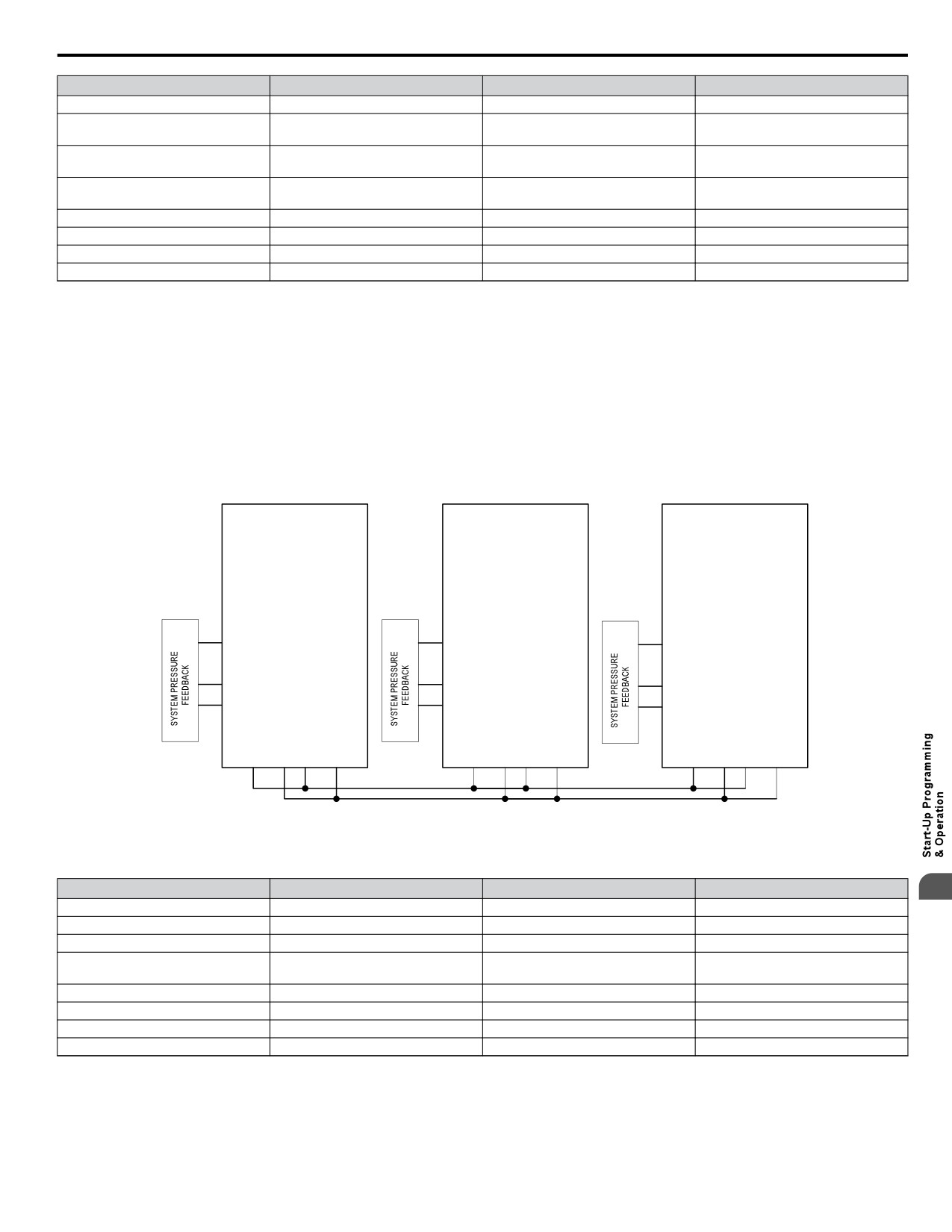
Triplex System Example
A customer who currently runs a duplex system would like to retrofit an existing triplex system with the following requirements:
• Three similarly sized pumps would run the system.
• A maximum of two drives should be running at any point; the third drive is a backup.
• Alternation should only happen when pumps are not running (sleeping).
• If one of the analog pressure feedback transducers should fail, read from a working one and notify the customer of the failure
by the alarm display.
• Setpoint is 90 PSI, feedback scale is 145 PSI, start level is 75 PSI.
S1
S1
S1
SN
SN
SN
Drive A
Drive B
Drive C
25 HP
25 HP
25 HP
+V
+V
+V
A1
A1
A1
A2
A2
A2
AC
AC
AC
R+
R-
S+
S-
R+
R-
S+
S-
R+
R-
S+
S-
Figure 4.16 Simplified Wiring Diagram
Table 4.14 Related Parameters for Triplex System Example
Description
Drive A <1>
Drive B <1>
Drive C <1>
4
Node Address
H5-01 = 1
H5-01 = 2
H5-01 = 3
Highest Node Address
P9-25 = 3
P9-25 = 3
P9-25 = 3
Pump Mode: 3 (Network)
P1-01 = 3
P1-01 = 3
P1-01 = 3
Feedback Source: 2 (Analog ->Net,
P9-02 = 2
P9-02 = 2
P9-02 = 2
with Alarm)
Alternation Mode: 3 (FIFO @ Sleep)
P9-04 = 3
P9-04 = 3
P9-04 = 3
Maximum Running Pumps
P9-23 = 2
P9-23 = 2
P9-23 = 2
Setpoint
U5-99 = 90 PSI
U5-99 = 90 PSI
U5-99 = 90 PSI
Start Level
P1-04 = 75 PSI
P1-04 = 75 PSI
P1-04 = 75 PSI
<1> All other multiplexing and alternation parameters are set to default settings.
99
4.8 iQpump Presets and Functions
n Multiplexing Stop History
Many irrigation-pumping skids consist of a PM pump (Pressure Maintenance) and typically two larger booster pumps to
maintain high flow peak demands. In many cases depending on the number of irrigation zones in combination with the type
of sprinkler heads used, the flow demand fluctuates and may not require the use of both larger booster pumps at the same time
until higher flow rates are required. The drive Controller "Run Stop" history ensures that both booster pumps alternate each
run cycle.
Table 4.15 P9-01, Lead Drive Selection, Detection Settings
Setting
Description
Next Available
0
Select next available drive on the network as the new lead drive
Lowest Runtime (default)
1
Select the iQpump Controller with the lowest runtime as the new lead drive
Stop History
2
Select the iQpump that had been stopped for the longest time.
Note:
The new lead drive selection also applies to Alternation (P9-03 > 0) and will use the Stop History list when finding the alternate.
Triplex Irrigation Booster System Example
When pressure is dropping, the PM Pump (if installed) will attempt to return the system pressure to the desired setpoint level.
If the PM Pump is not able to return the system to the setpoint pressure, typically due to a greater flow demand, the booster
pump #1 will be staged on.
The drive controller will speed up or slow down the pump as needed to maintain the system pressure. When flow decreases
and the pump system is no longer required to run, the system will go to sleep waiting for the pressure to drop. On the next run
cycle the PM pump will start up again, and instead of running booster pump #1, booster pump #2 is stages on, since booster
#1 ran during the last cycle.
This method ensures that during normal operation both booster pumps will operate evenly as lead or lag pumps each run cycle.
A triplex irrigation booster system has one PM Pump (pressure maintenance) and two larger booster pumps of the same
horsepower. The customer would like to ensure that the PM Pump is also the lead pump to recharge the system during low
flow usage, but during high demands the booster pumps alternate on each run cycle or if required will both run to support very
high flow demands.
• Jockey/PM Pump will also be lead to start.
• Jockey/PM Pump will stage booster pump 1 or 2 and stay running for 20 seconds and then shut off.
• Booster pump 1 will run system and if required, call for booster pump 2 or vice versa.
• On sleep mode, the lead drive for starting will swap back to Jockey/PM Pump.
• System setpoint 100 PSI.
• Pressure drop of 10 PSI will start the Jockey pump.
• All drives have individual transducers rated 200 PSI maximum, but if there is a transducer failure, switch to network.
Triplex Irrigation Booster System Related Parameters
Table 4.16 Related Parameters
Parameter No.
Parameter Name
PM Pump
Booster Pump 1
Booster Pump 2
H5-01
Drive Node Address
1
2
3
P1-01
Pump Mode
3
3
3
P1-03
Feedback Device Scaling
200 PSI
200 PSI
200 PSI
P1-04
Start / Draw Down Level
-10.0 PSI
-10.0 PSI
-10.0 PSI
P9-01
Lead Drive Selection
2
2
2
P9-02
Feedback Source
2
2
2
P9-07
Lag Fixed Speed Delay
20 s
5 s
5 s
P9-20
Allow Network Run
2
0
0
P9-21
Run Priority
7
8
8
P9-24
Lead Swap at Sleep
0 s
1 s
1 s
P9-25
Highest Node Address
3
3
3
U5-99
PID Setpoint Command
100 PSI
100 PSI
100 PSI
100
4.9 Auto-Tuning
4.9
Auto-Tuning
u Stationary Auto-Tuning
Type
Setting
Application Conditions and Benefits
Control Mode
For use when:
Stationary Auto-
Tuning
• The motor cable exceeds 50 m
for Line-to-Line
T1-01 = 2
• The motor cable length has been modified after Auto-Tuning has
V/f Control
Resistance (V/f and
been previously performed
OLV Control)
• When motor capacity and drive capacity differ
Note:
Auto-Tuning cannot be performed on permanent magnet motors (IPM, SPM, etc.).
u Before Auto-Tuning the Drive
Check the items below before Auto-Tuning the drive.
n Basic Auto-Tuning Preparations
• Auto-Tuning automatically determines the electrical characteristics of the motor. This is fundamentally different from other
types of Auto-Tuning features used in servo systems.
• Auto-Tuning requires the user to input data from the motor nameplate. Make sure the information written on the nameplate
is available before Auto-Tuning the drive.
• For best performance, be sure the drive input supply voltage equals or exceeds the motor rated voltage.
Note:
Performance can be enhanced by using a motor with a base voltage that is 20 V (40 V for 400 V class models) lower than the input supply
voltage. This may be of special importance when operating the motor above 90% of base speed, where high torque precision is required.
• Auto-Tuning is not possible with permanent magnet motors.
• To cancel Auto-Tuning, press the OFF key on the LCD operator.
• Table 4.17 describes digital input and output terminal status during Auto-Tuning.
Table 4.17 Digital Input and Output Operation During Auto-Tuning
Auto-Tuning Type
Digital Input
Digital Output
Stationary Auto-Tuning for Line-to-Line Resistance
Not available
Maintains the status at the start of Auto-Tuning
WARNING! Sudden Movement Hazard. Do not release the mechanical brake during stationary Auto-Tuning. Inadvertent brake release may
cause damage to equipment or injury to personnel. Ensure that the mechanical brake release circuit is not controlled by the drive multi-
function digital outputs.
n Notes on Stationary Auto-Tuning for Terminal Resistance Only
• If the motor cable lead length has been significantly modified after Auto-Tuning has already been performed, perform
Stationary Auto-Tuning with the new cables.
• Perform when using motor cables longer than 50 m with V/f Control.
WARNING! Electrical Shock Hazard. When executing stationary Auto-Tuning for line-to-line resistance only, the motor does not rotate,
however, power is applied. Do not touch the motor until Auto-Tuning is completed. Failure to comply may result in injury from electrical
shock.
4
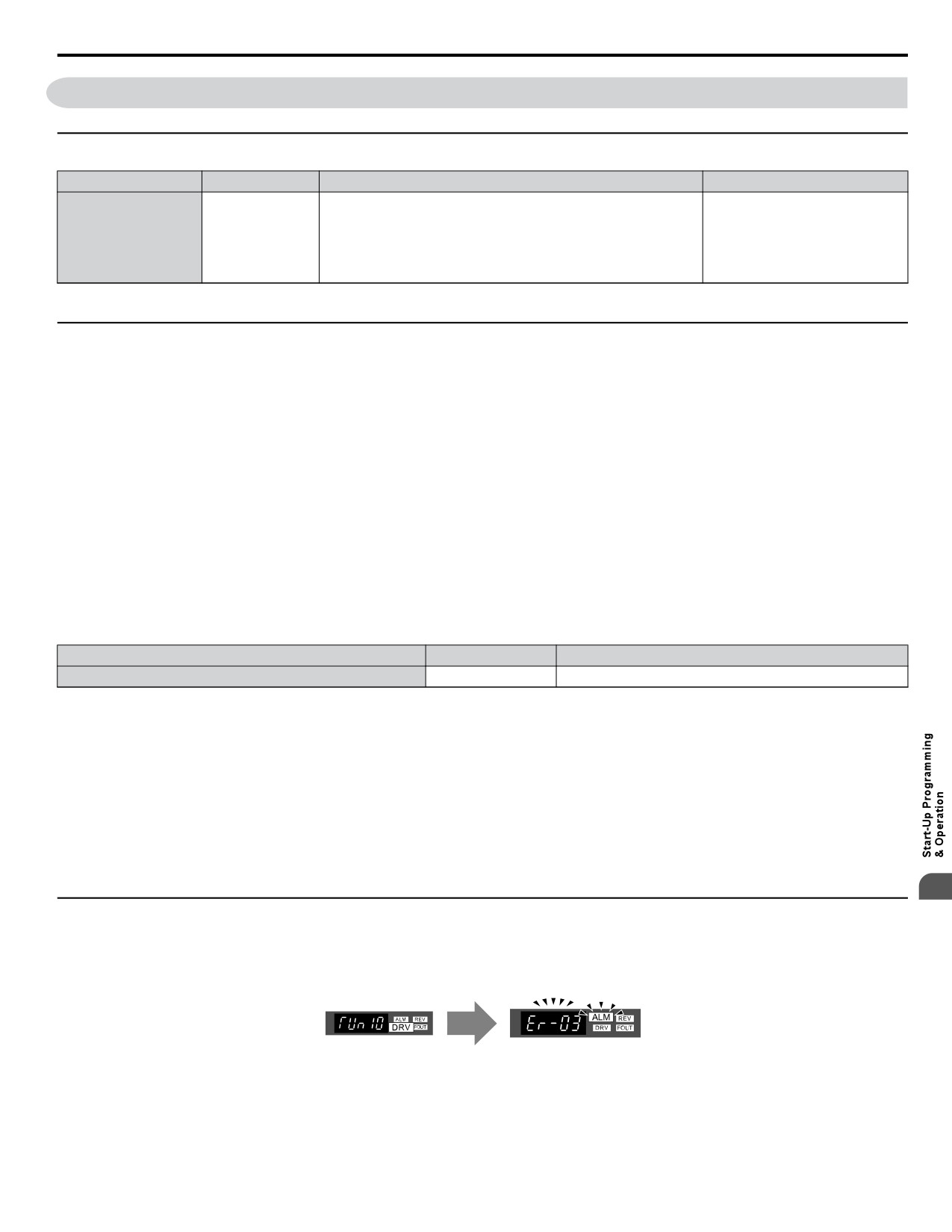
u Auto-Tuning Interruption and Fault Codes
If tuning results are abnormal or the STOP key is pressed before completion, Auto-Tuning will be interrupted and a fault code
will be displayed on the digital operator.
A
B
A - Normal Auto-Tuning Display
B - Auto-Tuning Interrupted
Figure 4.17 Auto-Tuning Interruption Display (Standard Digital LED Operator)
101
4.9 Auto-Tuning
u Performing Auto-Tuning
n Auto-Tuning Procedure
Auto-Tuning should generally be performed in the following steps.
1.
Refer to Before Auto-Tuning the Drive on page 101.
2.
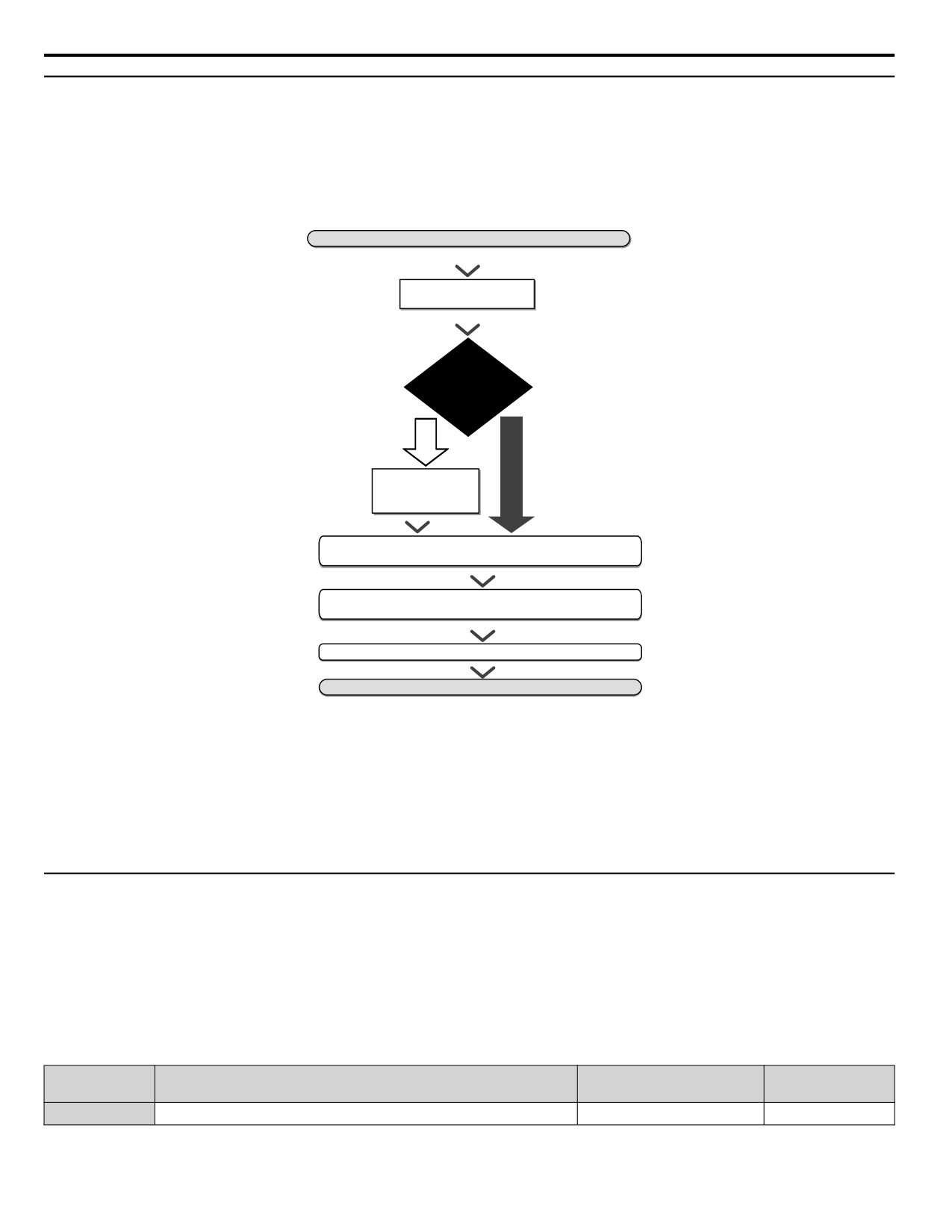
Determine which type of Auto-Tuning best fits the application requirements following Figure 4.18.
START
Select a V/f pattern
E1-03
NO
Is the cable
between the motor
and drive longer
than 50 m?
YES
NO
Stationary Auto-Tuning for
Line-to-Line Resistance
(T1-01 = 2)
Run the motor without the load.
Fine tune parameters if needed.
Connect the load and run the motor.
Fine tune parameters if needed.
Verify system operates as required.
Auto-Tuning finished.
Figure 4.18
3.
Enter the type 2 of Auto-Tuning to parameter T1-01.
4.
Enter the motor nameplate data.
5.
Start the Auto-Tuning process when prompted by the drive.
6.
If Auto-Tuning was successfully performed, do a test run without the load and make any necessary parameter adjustments.
7.
If the test run was successful, do a test run with the load connected and make parameter adjustments if necessary.
u Input Data for Auto-Tuning
The T1-oo parameters are used to set the Auto-Tuning input data.
Note:
1. Cycling power to the drive will reset any values set during the Auto-Tuning process to factory defaults.
2. For motors that are to be operated in the field weakening range, first perform the Auto-Tuning with the base data, i.e. the frequency at
which the motor is operating with its rated voltage (base frequency). After Auto-Tuning is complete, change the maximum frequency
E1-04 to the desired value.
n T1-01: Tuning Mode Selection
Sets the type of Auto-Tuning to be used. Refer to Stationary Auto-Tuning on page 101 for details on Stationary Auto-Tuning.
No.
Name
Setting Range
Default
T1-01
Auto-Tuning Mode Selection
2 (V/f)
2 (V/f)
Setting 2: Stationary Auto-Tuning for Line-to-Line Resistance
102
4.9 Auto-Tuning
n T1-02: Motor Rated Power
Used to set the motor rated power according to the motor nameplate value. For optimal performance, the motor rated power
should be between 50 and 100% of the drive rating.
No.
Name
Setting Range
Default
<1>
Determined by
T1-02
Motor Rated Power
o2-04 and C6-01
<1> The setting range differs based on drive software version.
PRG: 1016 and later: 0.03 to 650.00 kW
PRG: 1015 and earlier: 0.00 to 650.00 kW
n T1-04: Motor Rated Current
Used to set the motor rated current according to the motor nameplate value. For optimal performance in OLV, the motor rated
current should be between 50 and 100% of the drive rating. Enter the current at the motor base speed.
No.
Name
Setting Range
Default
10 to 200% of drive rated
Determined by
T1-04
Motor Rated Current
current
o2-04 and C6-01
4
103
4.10 No-Load Operation Test Run
4.10 No-Load Operation Test Run
u No-Load Operation Test Run
This section explains how to operate the drive with the motor uncoupled from the load during a test run.
n Before Starting the Motor
Check the following items before operation:
• Ensure the area around the motor is safe.
• Ensure external emergency stop circuitry is working properly and other safety precautions have been taken.
n During Operation
Check the following items during operation:
• The motor should rotate smoothly (i.e., no abnormal noise or oscillation).
• The motor should accelerate and decelerate smoothly.
n No-Load Operation Instructions (Standard Digital LED Operator)
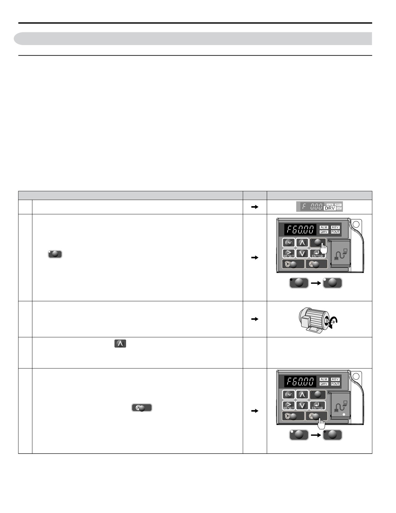
The following example illustrates a test run procedure using the digital operator.
Step
Display/Result
1.
Turn on the power to the drive. The initial display appears.
HAND
2.
Press HAND to give the drive a Run command from HAND mode. The HAND light will
turn on and the motor will rotate at 40 Hz.
AUTO
OFF
HAND
HAND
Off
On
Motor
3.
Ensure the motor is rotating in the correct direction and no faults or alarms occur.
Forward
If there is no error in step 3, press
to increase the frequency reference. Increase the
4.
frequency in 10 Hz increments verifying smooth operation results at all speeds. For each
-
-
frequency, monitor the drive output current (U1-03) through the LED operator to confirm
the current is well below the motor rated current. Example: 40 Hz → 60 Hz.
HAND
OFF
5.
The drive should operate normally. Press
to stop the motor. The HAND light is
off and the motor coasts to stop.
AUTO
OFF
HAND
HAND
On
Off
104
4.11 Test Run with Load Connected
4.11 Test Run with Load Connected
u Test Run with the Load Connected
After performing a no-load test run connect the load and proceed to run the motor and load together.
n Notes on Connected Machinery
• Clear the area around the motor.
• The motor should come to a complete stop without problems.
• Connect the machinery.
• Fasten all installation screws properly. Check that the motor and connected machinery are held in place.
• Confirm that the Fast-stop circuit or mechanical safety measures operate correctly.
• Be ready to press the OFF button in case of emergency.
n Checklist Before Operation
• The motor should rotate in the proper direction.
• The motor should accelerate and decelerate smoothly.
n Operating the Motor under Loaded Conditions
Test run the application similarly to the no-load test procedure when connecting the machinery to the motor.
• Check monitor parameter U1-03 to ensure there is no overcurrent.
• If the application permits running the load in the reverse direction, try changing motor direction and the frequency reference
while watching for abnormal motor oscillation or vibration.
• Correct any problems that occurs with hunting, oscillation, or other control-related issues.
4
105

4.12 Verifying Parameter Settings and Backing Up Changes
4.12 Verifying Parameter Settings and Backing Up Changes
Check changes to parameter settings as a result of Auto-Tuning using the Verify function. Refer to Verifying Parameter
Changes: Modified Constants Menu on page 83.
Save the verified parameter settings. Change the access level or set a password to the drive to prevent accidental modification
of parameter settings.
u Backing Up Parameter Values: o2-03
Performing the following procedure stores all parameters settings to drive memory where they can later be recalled if necessary.
Set o2-03 to “1” to save parameter changes. This saves all parameter settings, and then returns o2-03 to 0. The drive can now
“recall” the saved parameters by performing a “user-initialization” (A1-03 = 1110).
Setting
Default
No.
Parameter Name
Description
Range
Setting
Allows storing of parameter settings as a User Initialization Selection.
0: Saved/Not set
User Parameter
1: Set Defaults - Saves current parameter settings as user default settings.
o2-03
0 to 2
0
Default Value
2: Clear All - Clears the currently saved user settings. After saving the user parameter
set value, the items of 1110 (User Parameter Initialize) are displayed in A1-03 (User
Parameter Default Value).
Selects a method to initialize the parameters.
0: No Initialize
1110: User Initialize (The user must first program and store desired settings using
parameter o2-03)
2220: 2-Wire Initialization (parameter initialized prior to shipment)
3330: 3-Wire Initialization
5550: oPE4 Fault reset
Initialize
A1-03
6008: Pressure Control Application Preset
0 to 7771
0
Parameters
(Refer to Pump Application Presets on page 86)
6009: Pump Down Level Application Preset
(Refer to Pump Application Presets on page 86)
7770: General Purpose Application Preset
(Refer to Pump Application Presets on page 86)
7771: Submersible Motor General Purpose Operation
(Refer to Pump Application Presets on page 86)
u Parameter Access Level: A1-01
Setting the Access Level for “Operation only” (A1-01 = 0) allows the user to access parameters A1-oo and Uo-oo only.
Other parameters are not displayed.
Setting the Access Level for “User Parameters” (A1-01 = 1) allows the user to access parameters that have been previously
saved as User Parameters. This is helpful when displaying only the relevant parameters for a specific application.
Setting
No.
Parameter Name
Description
Default
Range
Selects which parameters are accessible via the digital operator.
0: Operation only (A1-01, -04, and -06 can be set and monitored. U parameters can be
monitored)
1: User Parameters (Only those recently changed among application parameters A2-01 to
Access Level
A1-01
-16 and A2-17 to -32 can be set and monitored)
0 to 3
2
Selection
2: Advanced Access Level (All parameters can be set and monitored)
3: Lock Parameters (Parameters that are normally visible in the advanced access level
(A1-01 = 2) are still visible, but the only parameters that can be changed are A1-01 and
A1-04.)
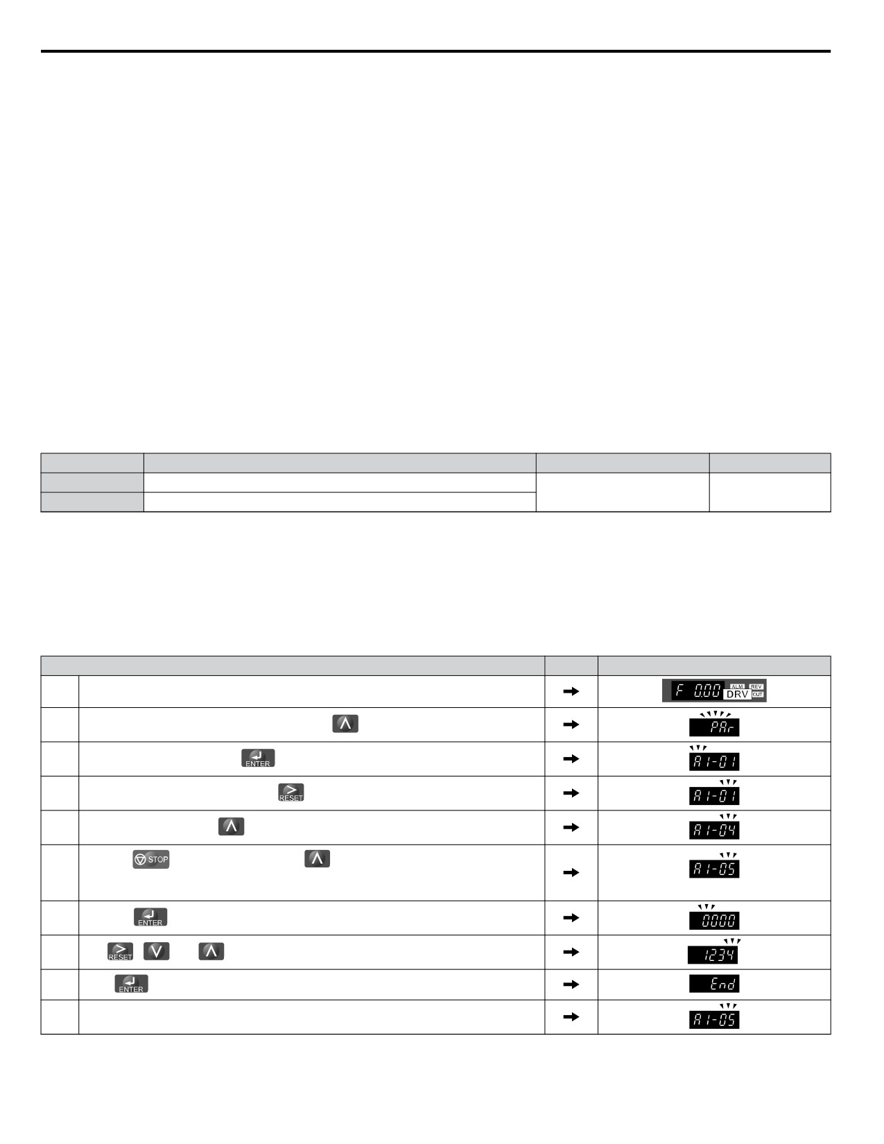
u Password Settings: A1-04, A1-05
The user can set a password to the drive to restrict access. The password is selected via parameter A1-05. The selected password
must be entered in parameter A1-04 to unlock parameter access (i.e., parameter setting A1-04 must match the value
programmed into A1-05). The following parameters cannot be viewed or edited until the value programmed into A1-04
correctly matches the value as programmed in parameter A1-05: A1-01, A1-02, A1-03, A1-06 and A2-01 through A2-33.
Note:
OFF
Parameter A1-05 is hidden from view. To display A1-05, access parameter A1-04 and simultaneously depress the
key and the
key.
106
4.12 Verifying Parameter Settings and Backing Up Changes
u Copy Function (Optional)
n USB/Copy Unit (JVOP-181)
The copy unit is an external option connected to the drive to copy parameter settings to another drive. It includes a USB adapter
to connect the drive to a PC.
n HOA RTC Operator (JVOP-183)
Digital operator with Real Time Clock function, LCD keypad display and copy function.
n DriveWizard iQpump
DriveWizard iQpump is a PC software tool for parameter management, monitoring, and diagnosis. DriveWizard iQpump can
load, store, and copy drive parameter settings. For details, refer to Help in the DriveWizard iQpump software.
4
107
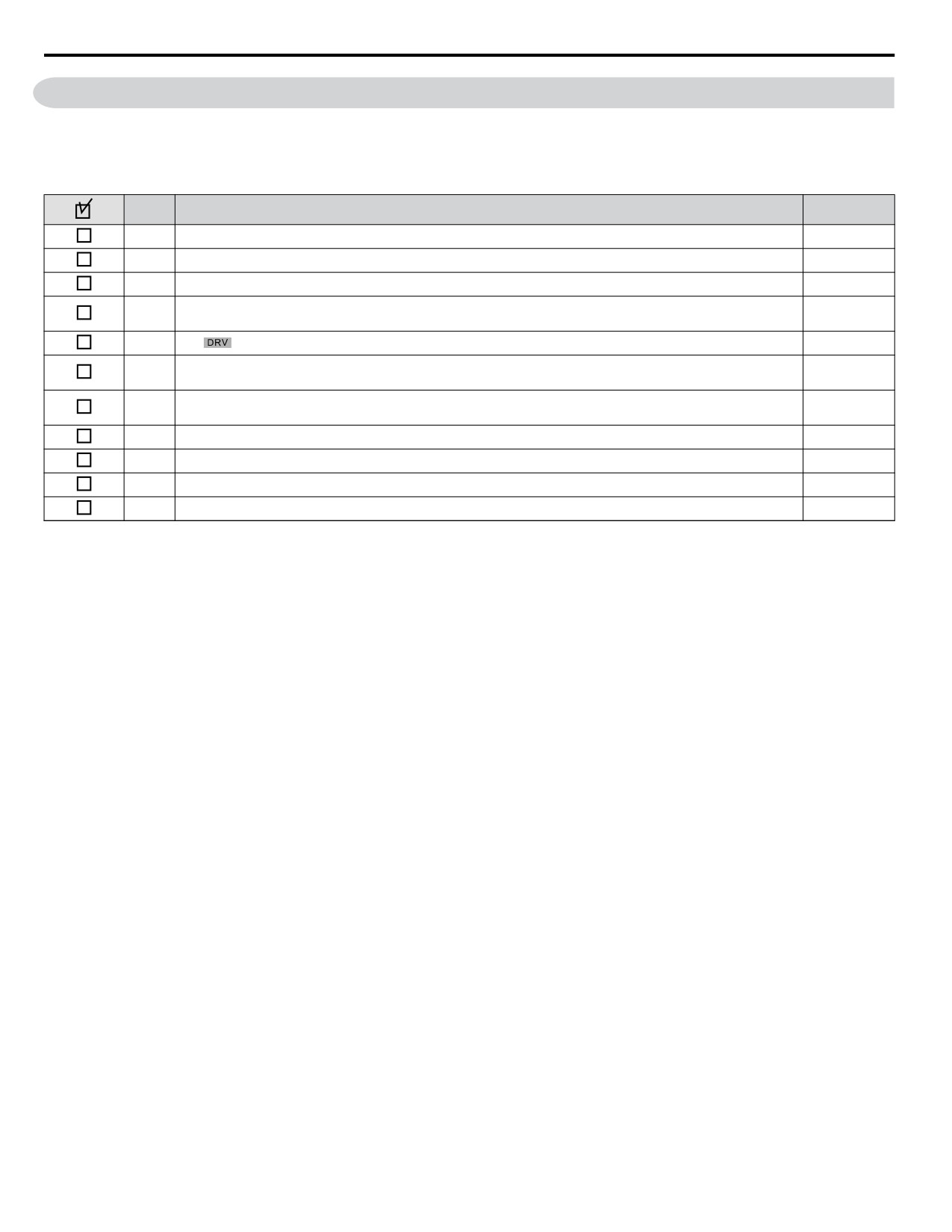
4.13 Test Run Checklist
4.13 Test Run Checklist
Review the checklist before performing a test run. Check each item that applies.
WARNING! Ensure start/stop and safety circuits are wired properly and in the correct state before energizing the drive. Failure to comply
could result in death or serious injury from moving equipment. When programmed for 3-Wire control, a momentary closure on terminal S1
may cause the drive to start.
No.
Checklist
Page
1
Thoroughly read the manual before performing a test run.
-
2
Turn the power on.
68
3
Set the voltage for the power supply to E1-01.
155
Select the best V/f pattern according to the application and motor characteristics.
4
-
Example: If using a motor with a rated frequency of 60.0 Hz, set E1-03 to “1”.
5
The
should illuminate after giving a run command using the AUTO key.
-
If the motor rotates in the opposite direction during the test run, switch two of the drive output terminals (U/T1,
6
68
V/T2, W/T3).
If the control circuit terminals should supply the frequency reference, select the correct voltage input signal level
7
68
(0 to 10 V) or the correct current input signal level (4 to 20 mA or 0 to 20 mA).
8
Set the proper voltage to terminal A1. (0 to 10 V).
115
9
Set the proper current to terminal A2. (4 to 20 mA or 0 to 20 mA).
115
10
When current input is used, set H3-09 to “2” (4 to 20 mA) or “3” (0 to 20 mA) and set H3-10 to “0”.
-
11
When current input is used, switch the drive built-in DIP switch S1 from the V-side (OFF) to I-side (ON).
-
108
5
Parameter Details
5.1
A: INITIALIZATION
110
5.2
B: APPLICATION
115
5.3
C: TUNING
140
5.4
D: REFERENCE SETTINGS
147
5.5
E: MOTOR PARAMETERS
155
5.6
F: OPTION SETTINGS
161
5.7
H: TERMINAL FUNCTIONS
163
5.8
L: PROTECTION FUNCTIONS
189
5.9
N: SPECIAL ADJUSTMENTS
213
5.10
O: OPERATOR RELATED SETTINGS
215
5.11
P: PUMP
223
5.12
Q: PID CONTROLLER
245
5.13
U: MONITOR PARAMETERS
247
109
5.1 A: Initialization
5.1
A: Initialization
The initialization group contains parameters associated with initial setup of the drive. Parameters involving the display
language, access levels, initialization, and password are located in this group.
u A1: Initialization
n A1-00: Language Selection
Selects the display language for the digital operator.
Note:
This parameter is not reset when the drive is initialized using parameter A1-03.
No.
Parameter Name
Setting Range
Default
A1-00
Language Selection
0 to 7
0
Setting 0: English
Setting 1: Japanese
Setting 2: German
Setting 3: French
Setting 4: Italian
Setting 5: Spanish
Setting 6: Portuguese
Setting 7: Chinese
n A1-01: Access Level Selection
Allows or restricts access to drive parameters.
No.
Parameter Name
Setting Range
Default
A1-01
Access Level Selection
0 to 3
2
Setting 0: Operation only
Access to only parameters A1-01, A1-04, and all U monitor parameters.
Setting 1: User Parameters
Access to only a specific list of parameters set to A2-01 through A2-32. These User Parameters can be accessed using the
Setup Mode of the digital operator.
Setting 2: Advanced Access Level (A) and Setup Access Level (S)
All parameters can be viewed and edited.
Setting 3: Lock Parameters
Parameters that are normally visible in the advanced access level (A1-01 = 2) are still visible, but the only parameters that can
be changed are A1-01 and A1-04.
The Auto Tuning and Pump Quick Setup menus will not be displayed.
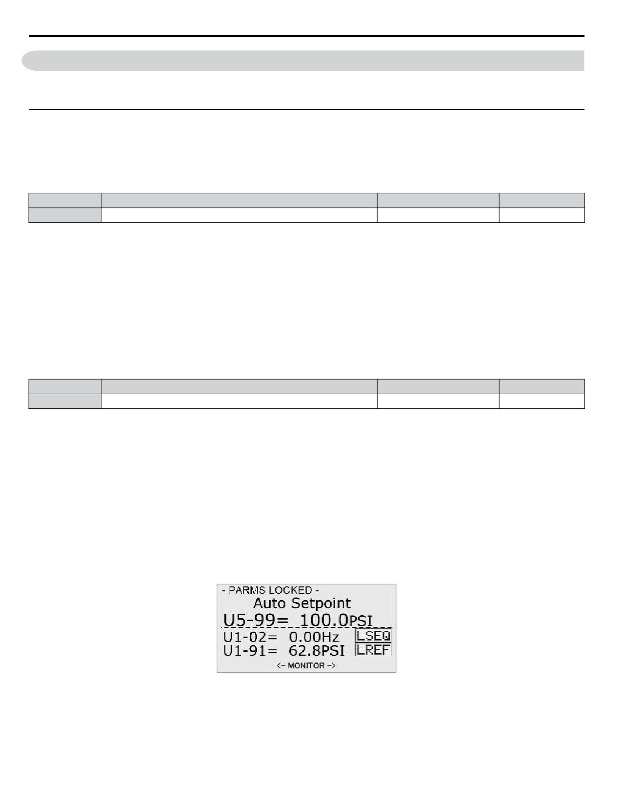
Figure 5.1 Help Message Example (Optional HOA Keypad, JVOP-183, Home Screen)
Notes on Parameter Access
• If the drive parameters are password protected by A1-04 and A1-05, parameters A1-00 through A1-03, A1-06, and all A2
parameters cannot be modified.
110
5.1 A: Initialization
• If a digital input terminal programmed for “Program lockout” (H1-oo = 1B) is enabled, parameter values cannot be
modified, even if A1-01 is set to 1 or 2.
• If parameters are changed via serial communication, it will not be possible to edit or change parameter settings with the
digital operator until an Enter command is issued to the drive from the serial communication.
n A1-03: Initialize Parameters
Resets parameters to default values or performs an Application Preset for fan or pump applications. After initialization, the
setting for A1-03 automatically returns to 0.
No.
Parameter Name
Setting Range
Default
0, 1110, 2220, 3330, 5550,
A1-03
Initialize Parameters
0
6008, 6009, 7770, 7771
Setting 1110: User Initialize
Resets parameters to the values selected by the user as User Settings. User Settings are stored when parameter o2-03 is set to
“1: Set defaults”.
Note:
User Initialization resets all parameters to a user-defined set of default values previously saved to the drive. Set parameter o2-03 to 2 to
clear the user-defined default values.
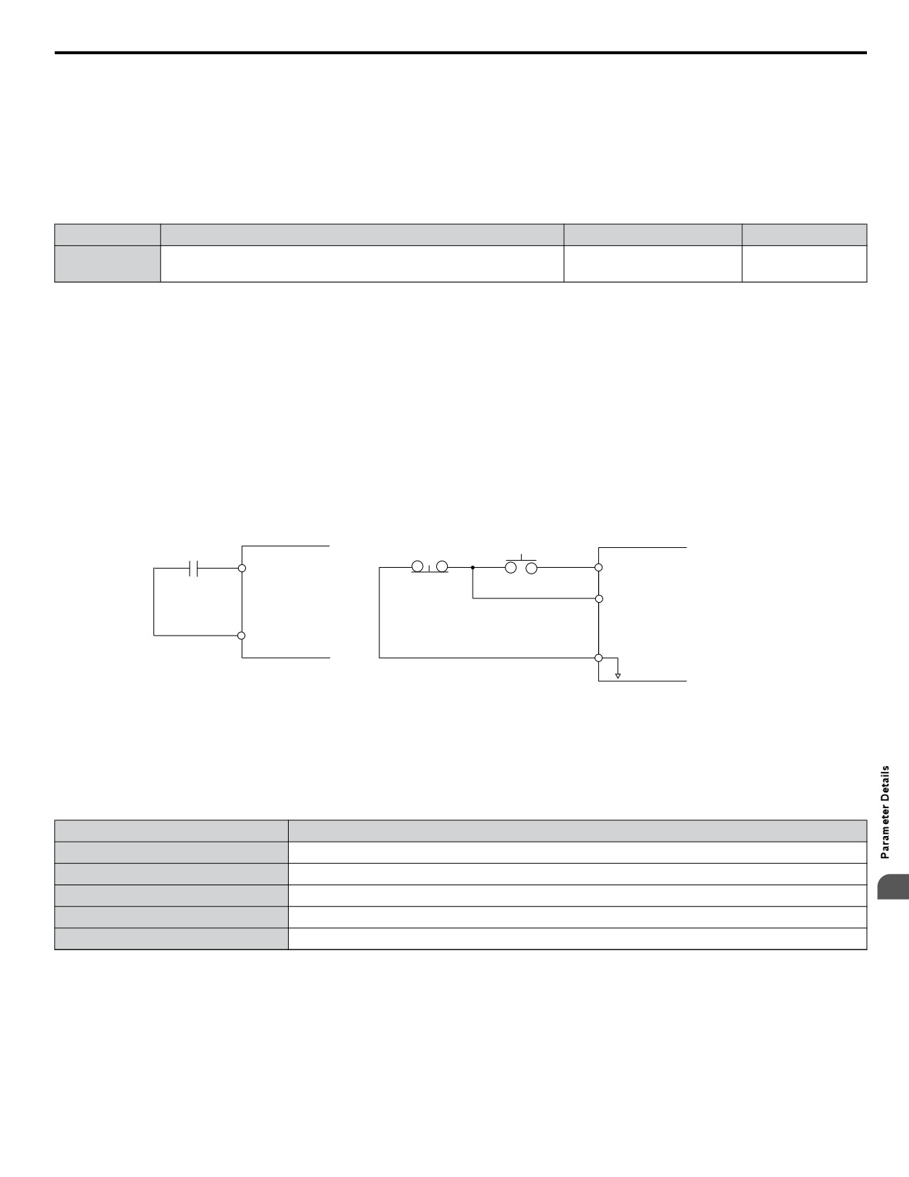
Setting 2220: 2-Wire Initialization
Resets parameters to default settings with digital inputs S1 and S2 configured as Forward run and Reverse run, respectively.
Setting 3330: 3-Wire Initialization
Resets parameters to default settings with digital inputs S1, S2, and S5 configured as Run, Stop, and Forward/Reverse
respectively.
Stop switch
Operation switch
(NC contact)
(NO contact)
S1
S1
Run command
FWD Run/Stop
(Run on momentary close)
S2
Stop command
(Stop on momentary open)
SN
SN
Sequence input common
2-Wire Control
3-Wire Control
Figure 5.2 2 & 3-Wire Control Wiring Examples
Notes on Parameter Initialization
The parameters shown in Table 5.1 will not be reset when the drive is initialized by setting A1-03 = 2220 or 3330.
Table 5.1 Parameters Not Changed by Drive Initialization
No.
Parameter Name
A1-00
Language Selection
E1-03
V/f Pattern Selection
5
F6-08
Communication Parameter Reset
L8-35
Installation Selection
o2-04
Drive/kVA Selection
Setting 5550: Terminal/Control Initialize
An oPE04 error appears on the digital operator when a terminal block with settings saved to its built-in memory is installed
in a drive that has edited parameters. Set A1-03 to 5550 to use the parameter settings saved to the terminal block memory.
Application Presets are available to facilitate drive setup for commonly used applications. Selecting one of these Application
Presets automatically assigns functions to the input and output terminals and sets a predefined group of parameters to values
appropriate for the selected application.
111
5.1 A: Initialization
In addition, the parameters most likely to be changed are assigned to the group of User Parameters, A2-01 through A2-16.
User Parameters are part of the Setup Group, which provides quicker access by eliminating the need to scroll through multiple
menus.
Refer to Pump Application Presets on page 86 for detailed information on Application Presets.
Setting 6008: Pressure Control
Application Preset for Pressure Control applications. Refer to Pump Application Presets on page 86 for a list of parameters
and default values for this Application Preset.
Setting 6009: Pump Down Level
Application Preset for Pump Down Level applications. Refer to Pump Application Presets on page 86 for a list of parameters
and default values for this Application Preset.
Setting 7770: General Purpose
General Purpose Application Preset. Refer to Pump Application Presets on page 86 for a list of parameters and default values
for this Application Preset.
Setting 7771: Submersible Motor General Purpose Operation
General Purpose Application Preset. Refer to Pump Application Presets on page 86 for a list of parameters and default values
for this Application Preset.
n A1-04, A1-05: Password and Password Setting
A1-04 is for entering the password when the drive is locked. A1-05 is a hidden parameter used to set the password.
No.
Parameter Name
Setting Range
Default
A1-04
Password
0 to 9999
0
A1-05
Password Setting
How to use the Password
The user can set a password for the drive to restrict access. The password is set to A1-05 and must be entered to A1-04 to
unlock parameter access. Until the correct password is entered, the following parameters cannot be viewed or edited: A1-01,
A1-03, A1-06, and A2-01 through A2-33.
The instructions below demonstrate how to set a new password. Here, the password set is “1234”. An explanation follows on
how to enter the password to unlock the parameters.
Table 5.2 Setting the Password for Parameter Lock (Standard Digital LED Operator)
Step
Display/Result
1.
Turn on the power to the drive. The initial display appears.
2.
Scroll to the Parameter Setup display and press
3.
Scroll to the right by pressing
4.
Select the flashing digits by pressing
5.
Select A1-04 by pressing
Press the
key while holding down
at the same time. A1-05 will appear.
6.
Note: A1-05 is normally hidden, but can be displayed by following the directions listed
“05” flashes
here.
7.
Press the
key.
8.
Use
,
and
to enter the password.
9.
Press
to save what was entered.
10.
The display automatically returns to the display shown in step 5.
112
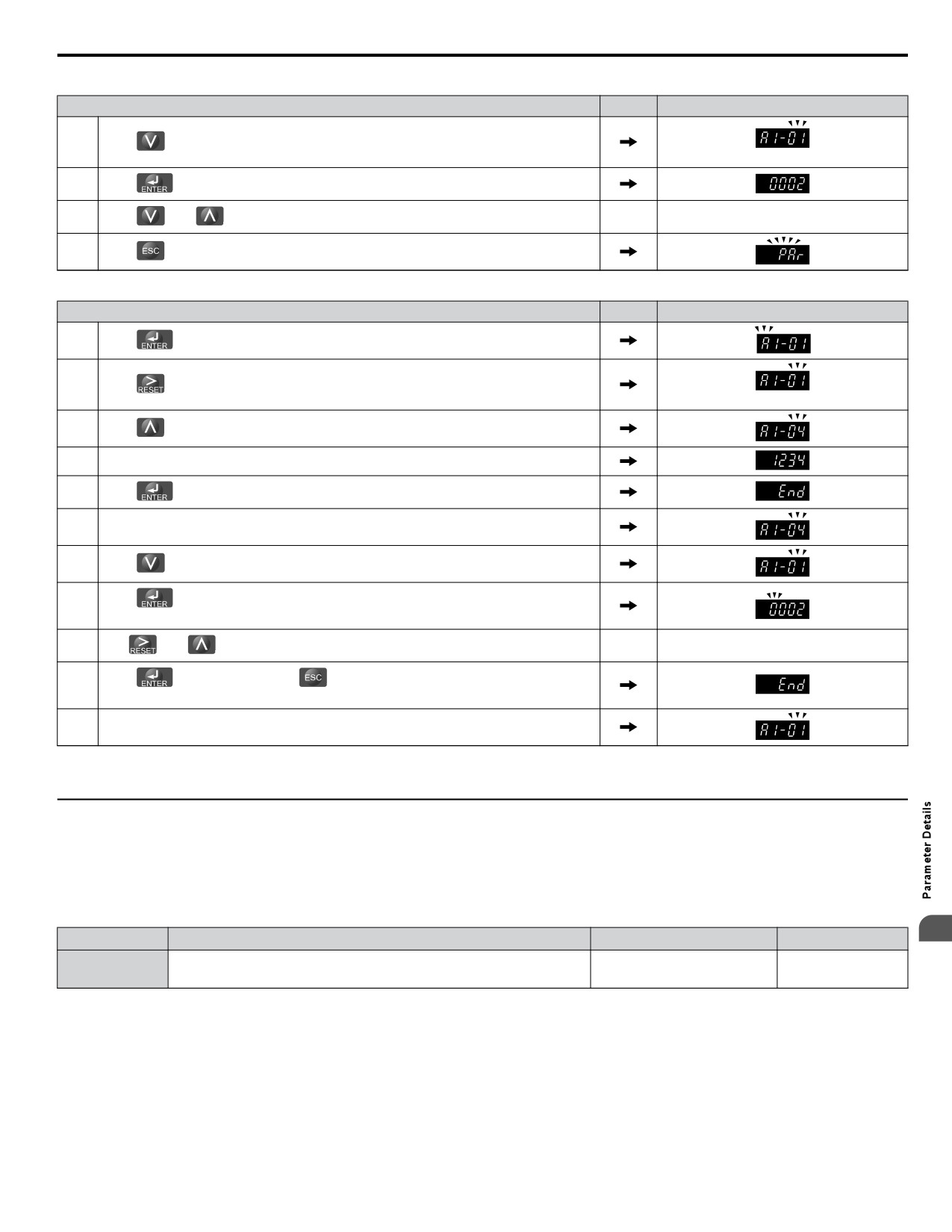
5.1 A: Initialization
Table 5.3 Check to see if A1-01 is locked (continuing from step 10 above)
Step
Display/Result
1.
Press
to display A1-01.
“01” flashes
2.
Press
to display the value set to A1-01.
3.
Press
and
, making sure that the setting values cannot be changed.
4.
Press
to return to the first display.
Table 5.4 Enter the Password to Unlock Parameters (continuing from step 4 above)
Step
Display/Result
1.
Press
to enter the parameter setup display.
2.
Press
to select the flashing digits as shown.
“01” flashes
3.
Press
to scroll to A1-04.
4.
Enter the password “1234”.
5.
Press
to save the new password.
6.
Drive returns to the parameter display.
7.
Press
and scroll to A1-01.
8.
Press
to display the value set to A1-01. If the first "0" blinks, parameter settings
are unlocked.
9.
Use
and
to change the value if desired. This is not typical.
10.
Press
to save the setting, or
to return to the previous display without saving
changes.
11.
The display automatically returns to the parameter display.
Note:
Parameter settings can be edited after entering the correct password. Performing a 2-Wire or 3-Wire initialization resets the password to
“0000”. Reenter the password to parameter A1-05 after drive initialization.
u A2: User Parameters
n A2-01 to A2-32: User Parameters
The user can select 32 parameters and assign them to A2-01 through A2-32. This saves time later scrolling through the
parameter menu. The list of User Parameters can also track the most recently edited settings and save those parameters to this
list.
5
No.
Parameter Name
Setting Range
Default
Depending on
A2-01 to A2-32
User Parameters 1 to 32
b1-01 to S6-02
A1-03
Saving User Parameters
To save specific parameters to A2-01 to A2-32, first set the access level to allow access to all parameters (A1-01 = 2). Next
assign the parameter number to the User Parameters list by entering it into one of the A2-oo parameters. By then setting
A1-01 to “1”, the access level can be restricted so that users can only set and reference the specific parameters saved as User
Parameters.
n A2-33: User Parameter Automatic Selection
A2-33 determines whether or not parameters that have been edited are saved to the User Parameters (A2-17 to A2-32) for
quick, easy access.
113
5.1 A: Initialization
No.
Parameter Name
Setting Range
Default
A2-33
User Parameter Automatic Selection
0 or 1
0
Setting 0: Do not save list of recently viewed parameters.
To manually select the parameters listed in the User Parameter group, set A2-33 to “0”.
Setting 1: Save history of recently viewed parameters.
By setting A2-33 to 1, all parameters that were recently edited will be automatically saved to A2-17 through A2-32. A total
of 16 parameters are saved in order with the most recently edited parameter set to A2-17. User parameters can be accessed
using the Setup mode of the digital operator.
114
5.2 b: Application
5.2
b: Application
Application parameters configure the source of the frequency reference, the Run command, DC Injection Braking, Speed
Search, various timer functions, PID control, the Dwell function, Energy Savings and a variety of other application-related
settings.
u b1: Mode of Operation
n b1-01: Frequency Reference Selection 1
Selects the frequency reference source 1 for the AUTO mode.
Note:
If a Run command is input to the drive but the frequency reference entered is 0 or below the minimum frequency, the RUN indicator LED
on the digital operator will light and the STOP indicator will flash.
No.
Parameter Name
Setting Range
Default
b1-01
Frequency Reference Selection 1
0 to 4
0
In order to run the drive and motor, the drive must receive a Run command and an Auto Setpoint command. Parameter b1-01
specifies the origin of the Auto setpoint when in AUTO Mode. Switch to AUTO mode by pressing the AUTO button on the
HOA keypad while the drive is stopped.
Note:
If a Run command is input to the drive without a corresponding Auto setpoint, the Run indicator on the HOA keypad will turn on and the
STOP indicator on the keypad will blink.
If the drive should follow the “HAND Reference” set by the HOA keypad, use HAND Mode by pressing the HAND key and
set P5-01 to “1: Hand Reference (P5-02).” The HAND reference can then be entered into the U1-01 monitor parameter in the
“-DRIVE-” Menu.
The drive offers the ability to provide four types of “Auto Setpoint” reference sources. These Auto Setpoint reference sources
are determined by the setting of b1-01 and the drive set to AUTO Mode by pressing the AUTO key on the keypad.
Prior to programming, it is recommended to select the system units (P1-02) and the feedback device, Scaling (P1- 03) first.
P1-03 will automatically scale the drive setpoint.
Example: P1-02 = 1: PSI
P1-03 = 200, feedback range = 200 PSI.
If the drive should follow an “Auto Set-Point” set by the HOA keypad: Set b1-01 to “0: Operator” (factory default). The Auto
setpoint can then be entered into the U5-99 monitor parameter in the “-DRIVE-” menu.
Setting 0: Operator (HOA keypad)
Using this setting, the frequency reference can be input by:
• switching between the multi-speed references in the d1-oo parameters.
• entering the frequency reference on the operator keypad.
This selection will also switch PID setpoint to Q1-01.
Setting 1: Terminals (Analog Input Terminals)
Using this setting, an analog frequency reference can be entered from:
• Terminal A1 using a 0 to 10 Vdc signal.
• Terminal A2 using either a 0 to 10 Vdc or a 0/4 to 20 mA signal.
Note:
Terminal A2 supports voltage and current input. The input signal type must be set up by setting DIP switch S1 and adjusting parameter
H3-09.
5
Entering only the main frequency reference:
Using Control Circuit Terminal A1 (0 to 10 Vdc voltage input):
Use a circuit such as the one shown in Figure 5.3 or an external 0 to 10 Vdc voltage source like a PLC analog output and set
the input level selection for A1 in parameter H3-02 as desired.
115
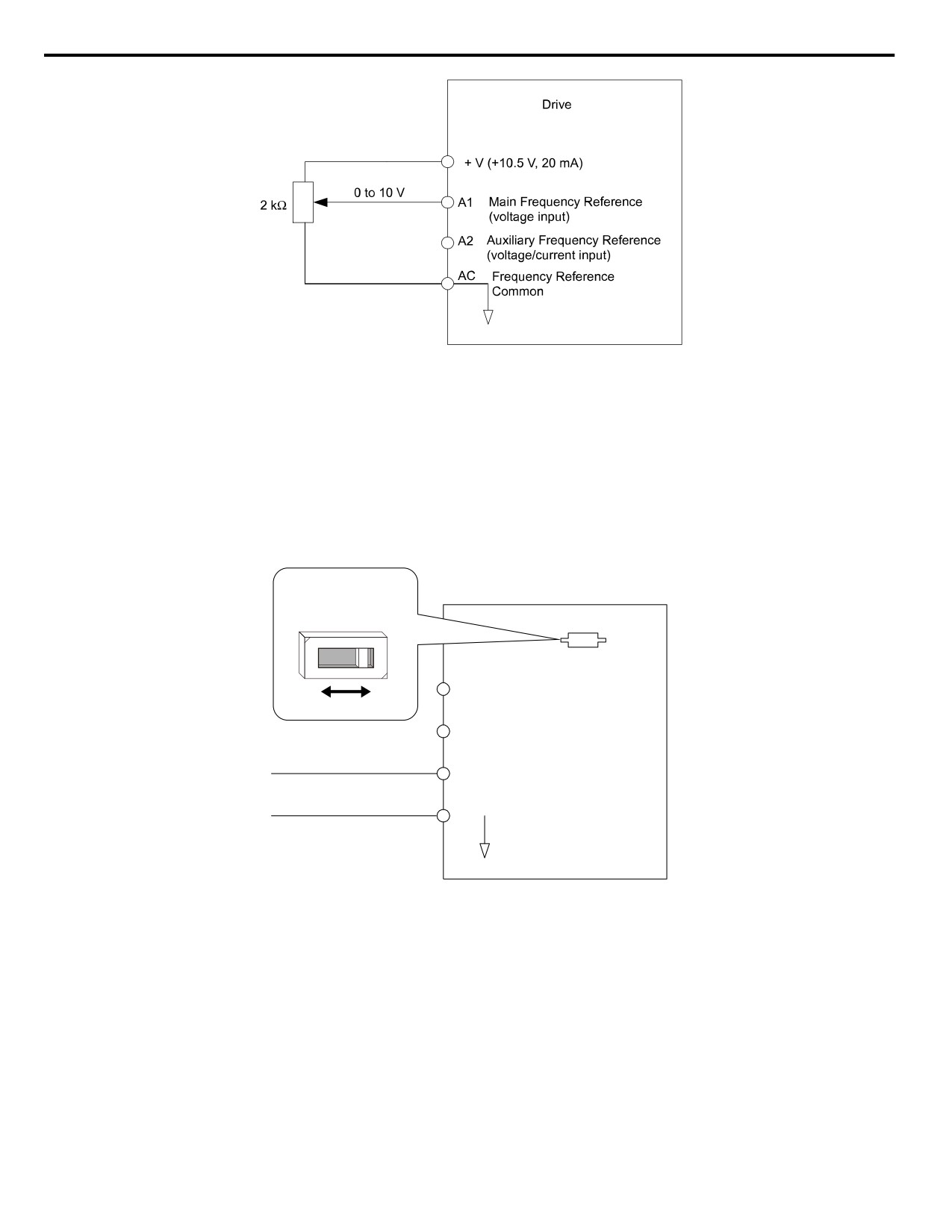
5.2 b: Application
Figure 5.3 Setting the Frequency Reference by Voltage Input
• Using Control Circuit Terminal A2 (0 to 10 Vdc voltage input)
Use the same connection as explained for terminal A1 for terminal A2. Make sure that switch S1 is set to “V” and set the
appropriate signal level for terminal A2 by entering 0 or 1 into parameter H3-09. The terminal A2 function must be set to
frequency bias by entering 0 into parameter H3-10.
• Using Control Circuit Terminal A2 (0/4 to 20 mA current input)
Connect input A2 to an external current source such as the one shown in Figure 5.4. Make sure that switch S1 is set to “I”
and set the appropriate signal level for terminal A2 by entering 2 (4 to 20 mA) or 3 (0 to 20 mA) into parameter H3-09. The
terminal A2 function must be set to frequency bias by entering 0 into parameter H3-10.
DIP switch S1
V
I
Drive
+V (+10.5 V, 20 mA power supply)
A1
Frequency reference
0 or 4 to 20 mA input
A2
Frequency reference bias
AC Analog common
Figure 5.4 Setting the Frequency Reference by Current Input
Switching between Main/Auxiliary Frequency References
The frequency reference input can be switched between terminal A1 (main) and terminal A2 (auxiliary). When using this
function:
• Make sure that b1-01 is set to “1” (Frequency reference from analog input).
• Set the terminal A2 function to auxiliary frequency (H3-10 = 2).
• Set one digital input to multi-speed 1 (H1-oo = 3, default for S5).
The frequency reference value is read from
• Terminal A1 when the digital input set for multi-speed 1 is open.
• Terminal A2 when the digital input set for multi-speed 1 is closed.
Figure 5.4 shows a wiring example for main/auxiliary reference switching using digital input S5.
116

5.2 b: Application
Figure 5.5 Switching between Analog Reference 1 and 2
Setting 2: MEMOBUS/Modbus Communications
This setting requires entering the frequency reference via the RS-485/422 serial communications port (control terminals R+,
R-, S+, S-).
To setup the drive to receive the “Auto Setpoint” from serial communication, set b1-01 to “2: Serial Com,” and connect the
RS-422/RS-485 serial communications cable to terminals R+, R-, S+, and S- on the control I/O terminal block. Refer to
117 to see the connection diagram using a PC to provide the auto setpoint reference to the drive.
Terminating
Resistor
Modbus RTU Communications
RS-422/RS-485
19.2 Kbps
RS-485 Communication Connection
Figure 5.6 PC or PLC Connection Diagram
5
Setting 3: Option card
This setting requires entering the frequency reference via an option board plugged into connector CN5 on the drive control
board. Consult the option board manual for instructions on integrating the drive with the communication system.
Note:
If the frequency reference source is set for Option PCB (b1-01 = 3), but an option board is not installed, an oPE05 Operator Programming
Error will be displayed on the digital operator and the drive will not run.
To setup the drive to receive the “Auto Setpoint” for a network communication option card, set b1-01 to “3: Option PCB”,
and plug a supported communication option card into the drive control PCB. Consult the manual supplied with the option for
instructions on integrating the drive into the network system.
Setting 4: Pulse Train Input
This setting requires a pulse train signal to terminal RP to provide the frequency reference. Follow the directions below to
verify that the pulse signal is working properly.
117
5.2 b: Application
Pulse Train Input Specifications
Response Frequency
0.5 to 32 kHz
Duty Cycle
30 to 70%
High Level Voltage
3.5 to 13.2 V
Low Level Voltage
0.0 to 0.8 V
Input Impedance
3 kΩ
Verifying the Pulse Train is Working Properly
• Set b1-01 to 4 and set H6-01 to 0.
• Set the H6-02 to the pulse train frequency value that equals 100% of the frequency reference.
• Enter a pulse train signal to terminal RP and check for the correct frequency reference on the display.
n b1-02: Run Command Selection 1
Determines the Run command source 1 in AUTO Mode.
The drive comes factory programmed for Start and Stop from the keypad, but the user can program the drive to receive a Run
command from four different inputs: digital operator, terminals, serial communications, or an option PCB.
WARNING! Sudden Movement Hazard. Clear personnel, secure equipment, and check sequence and safety circuitry before starting the
drive. Failure to comply could result in death or serious injury from moving equipment.
To set the drive to receive the Run command from the HOA keypad, set b1-02 to “0: Operator,” and the HAND key will be
used to provide the Run command to the drive.
To set the drive to receive the Run command from the external terminals, set b1-02 to “1: Terminals” and initiate an external
Run command by a contact closure between terminals S1 and SN.
Note:
Using the external terminals requires setting the drive to AUTO Mode by pressing the AUTO key.
No.
Parameter Name
Setting Range
Default
b1-02
Run Command Selection 1
0 to 3
0
Setting 0: Operator (HOA keypad)
This setting requires entering the Run command via the HOA keypad AUTO key and also illuminates the HAND indicator
on the digital operator.
Setting 1: Control Circuit Terminal
This setting requires entering the Run command via the digital input terminals using one of following sequences:
• 2-Wire sequence 1:
Two inputs (FWD/Stop-REV/Stop). Set A1-03 to 2220 to initialize the drive and preset terminals S1 and S2 to these
functions. This is the default setting of the drive.
• 2-Wire sequence 2:
Two inputs (Start/Stop-FWD/REV).
• 3-Wire sequence:
Three inputs (Start-Stop-FWD/REV). Set A1-03 to 3330 to initialize the drive and preset terminals S1, S2, and S5 to these
functions.
Setting 2: MEMOBUS/Modbus Communications
This setting requires entering the Run command via serial communications by connecting the RS-485/422 serial
communication cable to control terminals R+, R-, S+, and S- on the removable terminal block.
Setting 3: Option Card
This setting requires entering the Run command via the communication option board by plugging a communication option
board into the CN5 port on the control PCB. Refer to the option board manual for instructions on integrating the drive into
the communication system.
Note:
If b1-02 is set to 3, but an option board is not installed in CN5, an oPE05 operator programming error will be displayed on the digital
operator and the drive will not run.
n b1-03: Stopping Method Selection
Selects how the drive stops the motor when the Run command is removed or when a Stop command is entered.
Note:
Parameter b1-11, Run Delay at Stop (Back Spin Timer), is effective for all stopping methods (b1-03 = 0 to 3), not only Coast to Stop w/
Timer (b1-03 =3).
118
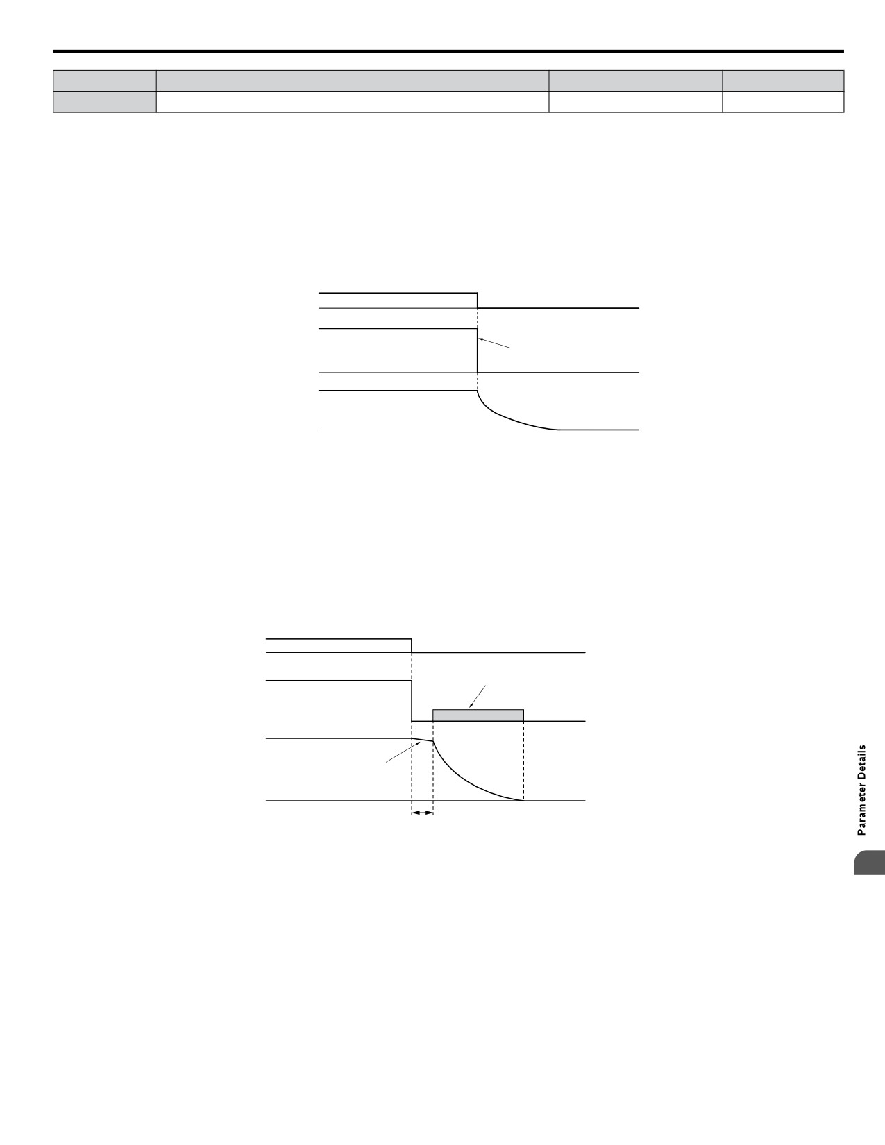
5.2 b: Application
No.
Parameter Name
Setting Range
Default
b1-03
Stopping Method Selection
0 to 3
1
Setting 0: Ramp to Stop
When the Run command is removed, the drive will decelerate the motor to stop. The deceleration rate is determined by the
active deceleration time. The default deceleration time is set to parameter C1-02.
When the output frequency falls below the level set in parameter b2-01, the drive will start DC injection, Zero Speed Control,
or Short Circuit Braking.
Setting 1: Coast to Stop
When the Run command is removed, the drive will shut off its output and the motor will coast (uncontrolled deceleration) to
stop. The stopping time is determined by the inertia and the friction in the driven system.
Run
command
ON
OFF
Output
frequency
Drive output is shut off
Motor speed
Figure 5.7 Coast to Stop
Note:
After a stop is initiated, any subsequent Run command entered will be ignored until the minimum baseblock time (L2-03) has expired. Do
not enter Run command until it has come to a complete stop. Use DC Injection at Start or Speed Search to restart the motor before it has
completely stopped.
Setting 2: DC Injection Braking to Stop
When the Run command is removed, the drive will enter baseblock (turn off its output) for the minimum baseblock time
(L2-03). When the minimum baseblock time has expired, the drive will inject the amount DC Injection Braking is set in
parameter b2-02 into the motor windings to brake the motor. The stopping time in DC Injection Braking to Stop is significantly
faster compared to Coast to Stop.
Run
command
ON
OFF
DC Injection Braking
Output
with the current set in
frequency
b2-02
Motor speed
Motor coasts
Minimum Baseblock
Time (L2-03)
Figure 5.8 DC Injection Braking to Stop
5
DC Injection Braking time is determined by the value set to b2-04 and the output frequency at the time the Run command is
removed. It can be calculated by:
(b2-04) x 10 x Output frequency
DC Injection brake time
=
Max. output frequency (E1-04)
119
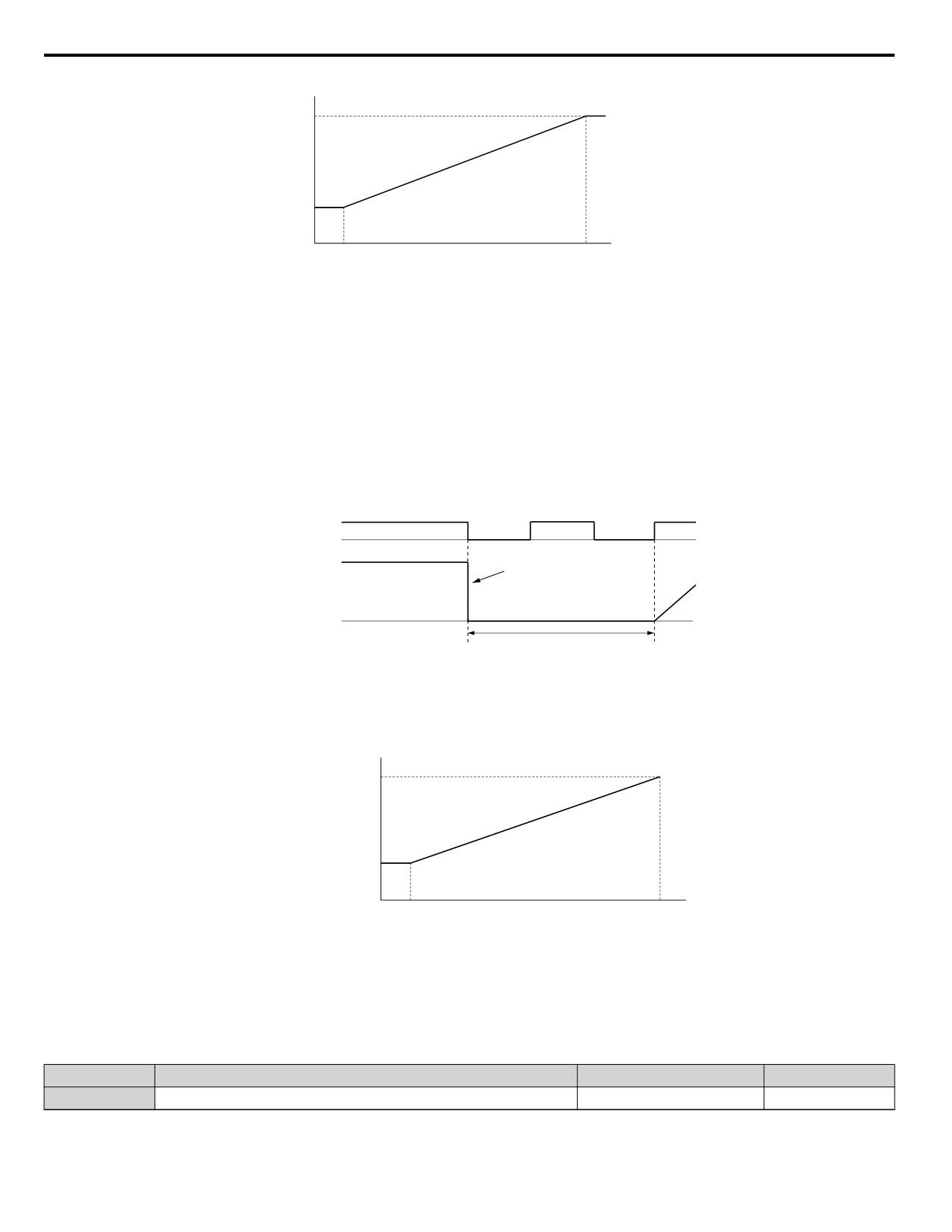
5.2 b: Application
DC Injection braking time
b2-0410
b2-04
Output frequency when
100%
10%
Stop command was entered
(Maximum output
frequency)
Figure 5.9 DC Injection Braking Time Depending on Output Frequency
Note:
If an overcurrent (oC) fault occurs during DC Injection Braking to Stop, lengthen the minimum baseblock time (L2-03) until the fault no
longer occurs.
Setting 3: Coast to Stop with Timer (Used for Back Spin Control on Vertical Turbine Pumps)
When the Run command is removed, the drive coasts to a stop. If parameter b1-11 = 0, the coast-timer (Run Delay at Stop)
becomes a value determined by a combination of output frequency and C1-02. However, if b1-11 > 0, the Run Delay at Stop
timer is set to b1-11. If the Run command is reissued during the Run Delay at Stop timer time, the drive WILL restart when
the timer expires without the need to re-cycle the Run command. The Run Delay at Stop timer will operate for both AUTO
Mode and HAND Mode. The Run Delay at Stop timer will still operate when the drive goes to sleep and then wakes up. During
the Run Delay at Stop timer execution, the HOA keypad will display a Start Delay message.
Run command
ON
OFF
ON
OFF
ON
Output
Drive output shut off
frequency
Run wait time t
Figure 5.10 Coast to Stop with Timer
The wait time t is determined by the output frequency when the Run command is removed and by the active deceleration time.
Run wait time t
Active deceleration time
Momentary Power Loss
Minimum Baseblock
Time (L2-03)
Min output
Output frequency
100%
frequency
when Stop command
(Max output
was entered
frequency)
Figure 5.11 Run Wait Time Depending on Output Frequency
n b1-04: Reverse Operation Selection
For some applications, reverse motor rotation is not appropriate and may even cause problems (e.g., air handling units, pumps,
etc.). Setting parameter b1-04 to 1 instructs the drive to ignore any Reverse run commands.
No.
Parameter Name
Setting Range
Default
b1-04
Reverse Operation Selection
0 or 1
0
Setting 0: Reverse Operation Enabled
Possible to operate the motor in both forward and reverse directions.
120