Yaskawa iQpump Micro AC Drive Compact Intelligent Pump Controller. User Manual (2014) - page 1
iQpump Micro AC Drive
Compact Intelligent Pump Controller
User Manual
Type: CIMR-PW
Models: 200 V Class, Single-Phase Input: 1 to 5 HP ND
200 V Class, Three-Phase Input: 1.5 to 25 HP ND
400 V Class, Three-Phase Input: 1 to 25 HP ND
To properly use the product, read this manual thoroughly and retain
for easy reference, inspection, and maintenance. Ensure the end user
receives this manual.
Receiving
1
Mechanical Installation
2
Electrical Installation
3
Start-Up Programming &
4
Operation
Parameter Details
5
Troubleshooting
6
Periodic Inspection &
7
Maintenance
Specifications A
Parameter List B
MEMOBUS/Modbus
Communications C
MANUAL NO. TOEP YAIQPM 03B
Standards Compliance D
Table of Contents
i.
PREFACE & GENERAL SAFETY
11
i.1
Preface
12
Applicable Documentation
12
Symbols
12
Terms and Abbreviations
12
Trademarks
12
i.2
General Safety
13
Supplemental Safety Information
13
Safety Messages
14
General Application Precautions
15
Motor Application Precautions
17
Drive Label Warning Example
19
Warranty Information
19
1.
RECEIVING
21
1.1
Section Safety
22
1.2
Model Number and Nameplate Check
23
Nameplate
23
2.
MECHANICAL INSTALLATION
25
2.1
Section Safety
26
2.2
Mechanical Installation
28
Installation Environment
28
Installation Orientation and Spacing
28
Exterior and Mounting Dimensions
30
3.
ELECTRICAL INSTALLATION
37
3.1
Section Safety
38
3.2
Standard Connection Diagram
40
Transducer Connection Diagrams
43
3.3
Terminal Block Configuration
44
3.4
Protective Covers
45
IP20/NEMA 1, UL Type 1 Front and Bottom Cover Removal and Installation
45
IP20/NEMA 1, UL Type 1 Top Cover Removal and Installation
46
3.5
Preparing IP66/NEMA 4X, UL Type 4X Enclosure Drives for Wiring
47
Select Cable Gland
47
IP66/NEMA 4X, UL Type 4X Enclosure Front Cover Removal and Installation
48
3
Table of Contents
3.6
Main Circuit Wiring
50
Main Circuit Terminal Functions
50
Wire Gauges and Tightening Torques
50
Main Circuit Terminal Power Supply and Motor Wiring
53
3.7
Control Circuit Wiring
55
Control Circuit Terminal Block Functions
55
Terminal Configuration
56
Wiring the Control Circuit Terminal
57
3.8
I/O Connections
59
Sinking/Sourcing Mode Switch
59
3.9
Main Frequency Reference
61
DIP Switch S1 Analog Input Signal Selection
61
3.10 Wiring Checklist
62
4.
START-UP PROGRAMMING & OPERATION
63
4.1
Section Safety
64
4.2
Drive Start-Up Preparation
66
Start-Up Checklist
66
4.3
Powering Up the Drive
68
Powering Up the Drive and Operation Status Display
68
4.4
Using the Standard Digital LED Operator
69
Keys, Displays, and LEDs
69
LED Screen Displays
70
AUTO LED and HAND LED Indications
70
Menu Structure for Digital LED Operator
72
4.5
The Drive and Programming Modes
73
Changing Parameter Settings or Values
73
4.6
Using the Optional HOA Keypad
74
Keys and Displays
74
LCD Display
75
ALARM (ALM) LED Displays
76
AUTO LED and HAND LED Indications
76
Setting the Real Time Clock
77
Menu Structure for HOA Keypad
81
Changing Parameter Settings or Values
82
Verifying Parameter Changes: Modified Constants Menu
83
4.7
Pump Application Presets
86
Parameters Set Depending on A1-03 Setting
86
Parameters Displayed Depending on A1-06 Setting
86
4.8
iQpump Presets and Functions
87
iQpump Presets
87
iQpump Functions
90
4.9
Auto-Tuning
101
Stationary Auto-Tuning
101
Before Auto-Tuning the Drive
101
Auto-Tuning Interruption and Fault Codes
101
Performing Auto-Tuning
102
Input Data for Auto-Tuning
102
4
Table of Contents
4.10 No-Load Operation Test Run
104
No-Load Operation Test Run
104
4.11 Test Run with Load Connected
105
Test Run with the Load Connected
105
4.12 Verifying Parameter Settings and Backing Up Changes
106
Backing Up Parameter Values: o2-03
106
Parameter Access Level: A1-01
106
Password Settings: A1-04, A1-05
106
Copy Function (Optional)
107
4.13 Test Run Checklist
108
5.
PARAMETER DETAILS
109
5.1
A: Initialization
110
A1: Initialization
110
A2: User Parameters
113
5.2
b: Application
115
b1: Mode of Operation
115
b2: DC Injection Braking
123
b4: Delay Timers
129
b5: PID Control
129
b6: Dwell Function
138
5.3
C: Tuning
140
C1: Acceleration and Deceleration Times
140
C2: S-Curve Characteristics
142
C3: Slip Compensation
143
C4: Torque Compensation
144
C6: Carrier Frequency
145
5.4
d: Reference Settings
147
d1: Frequency Reference
147
d2: Frequency Upper/Lower Limits
148
d3: Jump Frequency
149
d4: Frequency Hold and Up/Down 2 Function
150
5.5
E: Motor Parameters
155
E1: V/f Characteristics
155
E2: Motor 1 Parameters
159
5.6
F: Option Settings
161
F6: Serial Communications Option Card Settings
161
MECHATROLINK-II Parameters
162
MECHATROLINK-III Parameters
162
PROFIBUS-DP Parameters
162
DeviceNet Parameters
162
F7-01 to F7-42: EtherNet/IP and Modbus TCP/IP Option Parameters
162
5.7
H: Terminal Functions
163
H1: Multi-Function Digital Inputs
163
H2: Multi-Function Output
174
H4: Multi-Function Analog Output Terminals
186
H6: Pulse Train Input/Output
187
5.8
L: Protection Functions
189
L1: Motor Protection Functions
189
5
Table of Contents
L2: Momentary Power Loss Ride-Thru
193
L3: Stall Prevention
197
L4: Speed Agree/Frequency Reference Loss Detection
202
L5: Fault Restart
204
L6: Torque Detection
205
L8: Hardware Protection
207
5.9
n: Special Adjustments
213
n1: Hunting Prevention
213
n3: Overexcitation Braking
213
5.10
o: Operator Related Settings
215
o1: Display Settings and Selections
215
o2: Operator Key Selections
217
o3: Copy Function
219
o4: Maintenance Monitor Settings
220
5.11
P: Pump
223
P1: Pump Basic
223
P2: Pump Protection
228
P4: Pump Advanced
232
P5: Pump HAND Mode
235
P7: Anti-Jam
236
P9: Network Options
238
5.12
Q: PID Controller
245
Q1: Preset Setpoint
245
Q3: Output Current Limit
245
S6: Drive Protection
246
T: Motor Tuning
246
5.13
U: Monitor Parameters
247
U1: Operation Status Monitors
247
U2: Fault Trace
247
U3: Fault History
247
U4: Maintenance Monitors
247
U5: PID Monitors
247
U6: Control Monitors
247
U9: Operation Status Monitors
247
6.
TROUBLESHOOTING
249
6.1
Section Safety
250
6.2
Drive Faults, Alarms, Errors, and Messages
252
Types of Faults, Alarms, and Errors
252
6.3
Fault Detection
253
Fault Displays, Causes, and Possible Solutions
253
6.4
Alarm Detection
268
Alarm Codes, Causes, and Possible Solutions
268
6.5
Operator Programming Errors
280
Operator Programming Error Codes, Causes, and Possible Solutions
280
6.6
Copy Function Related Displays
283
Tasks, Errors, and Troubleshooting
283
6.7
Digital Operator Display Messages
285
Fault Reset Methods
286
6
Table of Contents
7.
PERIODIC INSPECTION & MAINTENANCE
287
7.1
Section Safety
288
7.2
Inspection
290
Recommended Periodic Inspection
290
7.3
Periodic Maintenance
292
Replacement Parts
292
7.4
Drive Cooling Fans
294
Number of IP20/NEMA 1, UL Type 1 Cooling Fans
294
IP20/NEMA 1, UL Type 1 Cooling Fan Replacement
295
Cooling Fan Replacement
295
Number of IP66/NEMA 4X, UL Type 4X Cooling Fans
297
IP66/NEMA 4X, UL Type 4X Cooling Fan Replacement
297
7.5
Drive Replacement
301
Serviceable Parts
301
Terminal Board Overview
301
Dismantling the Removable Terminal Block
301
Details on Terminal Board (TB) or Control Board (CNT) Replacement
304
A.
SPECIFICATIONS
307
A.1
Power Ratings
308
Single-Phase 200 V Class Drives
308
Three-Phase 200 V Class Drives
309
Three-Phase 400 V Class Drives
310
A.2
Drive Specifications
311
A.3
Drive Watt Loss Data
313
A.4
Drive Derating Data
314
Single-Phase Derating
314
Temperature Derating
315
Altitude Derating
315
B.
PARAMETER LIST
317
B.1
Parameter Groups
318
B.2
A: Initialization Parameters
319
A1: Initialization
319
A2: User Parameters
319
B.3
b: Application
320
b1: Operation Mode Selection
320
b2: DC Injection Braking and Short Circuit Braking
321
b3: Speed Search
321
b4: Timer Function
322
b5: PID Control
322
b6: Dwell Function
324
B.4
C: Tuning
325
C1: Acceleration and Deceleration Times
325
C2: S-Curve Characteristics
325
C3: Slip Compensation
326
C4: Torque Compensation
326
C6: Carrier Frequency
326
7
Table of Contents
B.5
d: References
327
d1: Frequency Reference
327
d2: Frequency Upper/Lower Limits
328
d3: Jump Frequency
328
d4: Frequency Reference Hold and Up/Down 2 Function
329
B.6
E: Motor Parameters
330
E1: V/f Pattern
330
E2: Motor 1 Parameters
331
B.7
F: Options
333
F6, F7: Communication Option Card
333
B.8
H Parameters: Multi-Function Terminals
335
H1: Multi-Function Digital Inputs
335
H2: Multi-Function Digital Outputs
339
H3: Multi-Function Analog Inputs
341
H4: Analog Outputs
343
H5: MEMOBUS/Modbus Serial Communication
343
H6: Pulse Train Input
344
B.9
L: Protection Function
345
L1: Motor Protection
345
L2: Momentary Power Loss Ride-Thru
346
L3: Stall Prevention
346
L4: Speed Detection
348
L5: Fault Restart
348
L6: Torque Detection
349
L8: Drive Protection
350
B.10
n: Advanced Performance Set-Up
352
n1: Hunting Prevention
352
n3: Overexcitation Braking
352
B.11
o: Operator Related Parameters
353
o1: HOA Keypad Display Selection
353
o2: HOA Keypad Keypad Functions
354
o3: Copy Function
354
o4: Maintenance Monitor Settings
355
B.12
P: Pump Parameters
356
P1: Pump Basic
356
P2: Pump Protection
358
P4: Pump Advanced
359
P5: Pump HAND Mode
361
P7: Anti-Jam
362
P9: Network Options
362
B.13
Q: PID Controller Parameters
366
Q1: Preset Setpoint
366
Q3: Output Current Limit
366
B.14
S: Special Application
367
S6: Protection
367
B.15
T: Motor Tuning
368
T1: Induction Motor Auto-Tuning
368
B.16
U: Monitors
369
U1: Operation Status Monitors
369
8
Table of Contents
U2: Fault Trace
372
U3: Fault History
372
U4: Maintenance Monitors
374
U5: PID Monitors
376
U6: Control Monitors
376
U9: Operation Status Monitors
376
B.17 Defaults by Drive Model
377
C.
MEMOBUS/MODBUS COMMUNICATIONS
383
C.1
Section Safety
384
C.2
MEMOBUS/Modbus Configuration
385
C.3
Communication Specifications
386
C.4
Connecting to a Network
387
Network Cable Connection
387
Wiring Diagram for Multiple Connections
388
Network Termination
390
C.5
MEMOBUS/Modbus Setup Parameters
391
MEMOBUS/Modbus Serial Communication
391
C.6
Drive Operations by MEMOBUS/Modbus
395
Observing the Drive Operation
395
Controlling the Drive
395
C.7
Communications Timing
396
Command Messages from Master to Drive
396
Response Messages from Drive to Master
396
C.8
Message Format
397
Message Content
397
Slave Address
397
Function Code
397
Data
397
Error Check
397
C.9
Message Examples
399
Reading Drive MEMOBUS/Modbus Register Contents
399
Loopback Test
399
Writing to Multiple Registers
400
C.10
MEMOBUS/Modbus Data Table
401
Command Data
401
Monitor Data
403
Broadcast Messages
412
Fault Trace Contents
412
Alarm Register Contents
413
C.11
Enter Command
415
Enter Command Types
415
C.12
Communication Errors
416
MEMOBUS/Modbus Error Codes
416
Slave Not Responding
416
C.13
Self-Diagnostics
417
D.
STANDARDS COMPLIANCE
419
9
Table of Contents
D.1
Section Safety
420
D.2
European Standards
422
CE Low Voltage Directive Compliance
422
EMC Guidelines Compliance
424
D.3
UL and CSA Standards
427
UL Standards Compliance
427
CSA Standards Compliance
432
Drive Motor Overload Protection
432
Safe Disable Function Description
433
Installation
433
D.1
UL Standards
435
UL Standards Compliance
435
IP66/NEMA 4X, UL Type 4X Conditions of Acceptability
435
Main Circuit Terminal Wiring
435
Drive Motor Overload Protection
440
10
i
Preface & General Safety
This section provides safety messages pertinent to this product that, if not heeded, may result in fatality,
personal injury, or equipment damage. Yaskawa is not responsible for the consequences of ignoring
these instructions.
i.1
PREFACE
12
i.2
GENERAL SAFETY
13
11
i.1 Preface
i.1
Preface
Yaskawa manufactures products used as components in a wide variety of industrial systems and equipment. The selection and
application of Yaskawa products remain the responsibility of the equipment manufacturer or end user. Yaskawa accepts no
responsibility for the way its products are incorporated into the final system design. Under no circumstances should any
Yaskawa product be incorporated into any product or design as the exclusive or sole safety control. Without exception, all
controls should be designed to detect faults dynamically and fail safely under all circumstances. All systems or equipment
designed to incorporate a product manufactured by Yaskawa must be supplied to the end user with appropriate warnings and
instructions as to the safe use and operation of that part. Any warnings provided by Yaskawa must be promptly provided to
the end user. Yaskawa offers an express warranty only as to the quality of its products in conforming to standards and
specifications published in the Yaskawa manual. NO OTHER WARRANTY, EXPRESS OR IMPLIED, IS OFFERED.
Yaskawa assumes no liability for any personal injury, property damage, losses, or claims arising from misapplication of its
products.
This manual is designed to ensure correct and suitable application of drives. Read this manual before attempting to install,
operate, maintain, or inspect a drive and keep it in a safe, convenient location for future reference. Be sure you understand all
precautions and safety information before attempting application.
u Applicable Documentation
The following manuals are available for iQpump Micro drives:
iQpump Micro Quick Start Procedure (TOEPYAIQPM01)
This sheet is packaged together with the drive and contains a step-by-step guide to enable the user to properly wire the drive
and motor and connect the 24 V power supply.
iQpump Micro AC Drive Quick Start Guide (TOEPYAIQPM02)
Read this guide first. This guide is packaged together with the product and contains basic information required to install and
Micro
wire the drive. It also gives an overview of fault diagnostics, maintenance, and parameter settings. The purpose of this guide
WARNING
Risk of electric shock.
is to prepare the drive for basic operation. The most recent version of this manual is available for download on our
Read manual before installing.
Wait 5 minutes for capacitor discharge after
disconnecting power supply.
AVERTISSEMENT
electrique.
Risque de decharge
documentation website, www.yaskawa.com.
Lire le manuel avant l'installation.
Attendre 5 minutes apres la coupure de l'alimentation,
pour permettre la decharge des condensateurs.
iQpump Micro AC Drive User Manual (TOEPYAIQPM03)
This manual provides detailed information on parameter settings, fault diagnostics, and drive functions. Use this manual to
expand drive functionality and to take advantage of higher performance features. The most recent version of this manual is
available for download on our documentation website, www.yaskawa.com.
u Symbols
Note:
Indicates a supplement or precaution that does not cause drive damage.
TERMS
Indicates a term or definition used in this manual.
u Terms and Abbreviations
• Drive: Yaskawa iQpump Micro Intelligent Pump Controller
• BCD: Binary Coded Decimal
• H: Hexadecimal Number Format
• IGBT: Insulated Gate Bipolar Transistor
• kbps: Kilobits per Second
• MAC: Media Access Control
• Mbps: Megabits per Second
• r/min: Revolutions per Minute
• V/f: V/f Control
u Trademarks
• Modbus is a trademark of Schneider Electric.
• Other companies and product names mentioned in this manual are trademarks of those companies.
12
i.2 General Safety
i.2
General Safety
u Supplemental Safety Information
General Precautions
• The diagrams in this manual may be indicated without covers or safety shields to show details. Replace the covers or shields before
operating the drive and run the drive according to the instructions described in this manual.
• Any illustrations, photographs, or examples used in this manual are provided as examples only and may not apply to all products to
which this manual is applicable.
• The products and specifications described in this manual or the content and presentation of the manual may be changed without notice
to improve the product and/or the manual.
• When ordering a new copy of the manual due to damage or loss, contact your Yaskawa representative or the nearest Yaskawa sales
office and provide the manual number shown on the front cover.
• If nameplate becomes worn or damaged, order a replacement from your Yaskawa representative or the nearest Yaskawa sales office.
WARNING
Read and understand this manual before installing, operating or servicing this drive. The drive must be installed according
to this manual and local codes.
The following conventions are used to indicate safety messages in this manual. Failure to heed these messages could result
in serious or fatal injury or damage to the products or to related equipment and systems.
DANGER
Indicates a hazardous situation, which, if not avoided, will result in death or serious injury.
WARNING
Indicates a hazardous situation, which, if not avoided, could result in death or serious injury.
WARNING! may also be indicated by a bold key word embedded in the text followed by an italicized safety message.
CAUTION
Indicates a hazardous situation, which, if not avoided, could result in minor or moderate injury.
CAUTION! may also be indicated by a bold key word embedded in the text followed by an italicized safety message.
NOTICE
Indicates a property damage message.
NOTICE: may also be indicated by a bold key word embedded in the text followed by an italicized safety message.
13
i.2 General Safety
u Safety Messages
DANGER
Heed the safety messages in this manual.
Failure to comply will result in death or serious injury.
The operating company is responsible for any injuries or equipment damage resulting from failure to heed the warnings in
this manual.
Electrical Shock Hazard
Before servicing, disconnect all power to the equipment.
The internal capacitor remains charged even after the power supply is turned off. The charge indicator LED will extinguish
when the DC bus voltage is below 50 Vdc. To prevent electric shock, wait for at least the time specified on the warning label,
once all indicators are OFF, measure for unsafe voltages to confirm the drive is safe prior to servicing.
Failure to comply will result in death or serious injury.
WARNING
Sudden Movement Hazard
System may start unexpectedly upon application of power, resulting in death or serious injury.
Clear all personnel from the drive, motor and machine area before applying power. Secure covers, couplings, shaft keys and
machine loads before applying power to the drive.
Electrical Shock Hazard
Do not attempt to modify or alter the drive in any way not explained in this manual.
Failure to comply could result in death or serious injury.
Yaskawa is not responsible for any modification of the product made by the user. This product must not be modified.
Do not allow unqualified personnel to use equipment.
Failure to comply could result in death or serious injury.
Installation, maintenance, inspection, and service must be performed only by authorized personnel familiar with installation,
adjustment and maintenance of AC drives.
Do not remove covers or touch circuit boards while the power is on.
Failure to comply could result in death or serious injury.
Make sure the protective earthing conductor complies with technical standards and local safety regulations.
Always use appropriate equipment for Ground Fault Circuit Interrupters (GFCIs).
The drive can cause a residual current with a DC component in the protective earthing conductor. Where a residual current
operated protective or monitoring device is used for protection in case of direct or indirect contact, always use a type B GFCI
according to IEC/EN 60755.
Fire Hazard
Do not use an improper voltage source.
Failure to comply could result in death or serious injury by fire.
Verify that the rated voltage of the drive matches the voltage of the incoming power supply before applying power.
Install adequate branch circuit protection according to applicable local codes and this Installation Manual. Failure
to comply could result in fire and damage to the drive or injury to personnel.
The device is suitable for use on a circuit capable of delivering not more than 100,000 RMS symmetrical amperes, 240 Vac
maximum (200 V class) and 480 Vac maximum (400 V class) when protected by branch circuit protection devices specified
in this document.
14
i.2 General Safety
WARNING
Crush Hazard
Do not use this drive in lifting applications without installing external safety circuitry to prevent accidental dropping
of the load.
The drive does not possess built-in load drop protection for lifting applications.
Failure to comply could result in death or serious injury from falling loads.
Install electrical and/or mechanical safety circuit mechanisms independent of drive circuitry.
CAUTION
Crush Hazard
Do not carry the drive by the front cover.
Failure to comply may result in minor or moderate injury from the main body of the drive falling.
NOTICE
Observe proper electrostatic discharge procedures (ESD) when handling the drive and circuit boards. Failure to
comply may result in ESD damage to the drive circuitry.
Do not perform a withstand voltage test or megger test on any part of the drive.
Failure to comply could result in damage to the sensitive devices within the drive.
Do not operate damaged equipment.
Failure to comply could result in further damage to the equipment. Do not connect or operate any equipment with visible
damage or missing parts.
If a fuse is blown or a Ground Fault Circuit Interrupter (GFCI) is tripped, check the wiring and the selection of the
peripheral devices.
Check for short circuits or ground faults on the secondary side of fuses and GFCIs and check the wiring and the selection of
peripheral devices. Remove the cause of the problem and then turn the power supply off and on again. If the cause cannot
be identified, do not turn on the power supply or attempt to operate the equipment.
Do not restart the drive immediately operate the peripheral devices if a fuse is blown or a GFCI is tripped.
Check the wiring and the selection of peripheral devices to identify the cause. Contact your supplier before restarting the
drive or the peripheral devices if the cause cannot be identified.
Do not expose the drive to halogen group disinfectants.
Failure to comply may cause damage to the electrical components in the drive.
Do not pack the drive in wooden materials that have been fumigated or sterilized. Do not sterilize the entire package after
the product is packed.
u General Application Precautions
n Selection
Installing a Reactor
Use an AC reactor or DC link choke in the following situations:
• to suppress harmonic current.
• to smooth peak current that results from capacitor switching.
• when the power supply is above 600 kVA.
• when the drive is running from a power supply system with thyristor converters.
15
i.2 General Safety
4000
Power supply harmonics
reactor required
Power Supply
Capacity (kVA)
600
Reactor
unnecessary
0
60
400
Drive Capacity (kVA)
Figure i.1 Installing a Reactor
Drive Capacity
For specialized motors, make sure that the motor rated current is less than the rated output current for the drive.
When running more than one motor in parallel from a single drive, the capacity of the drive should be larger than [total motor
rated current × 1.1].
Starting Torque
The overload rating of the drive determines the starting and accelerating characteristics of the motor. Expect lower running
torque than when running the motor from line power. To get more starting torque, use a larger drive or increase both the motor
and drive capacity.
Emergency/Fast Stop
During a drive fault condition, a protective circuit is activated and drive output is shut off. The motor may coast to a stop or
attempt to decelerate depending on parameter settings. If the emergency/fast stop cannot stop the load as fast as desired, a
customer-supplied mechanical brake may be required. Test emergency stop circuitry before putting drive into operation.
n Repetitive Starting/Stopping
Applications with frequent starts and stops often exceed 150% of their rated current values. Heat stress generated from
repetitive high current can shorten the life span of the IGBTs. The expected lifetime for the IGBTs is about 8 million start and
stop cycles with a 4 kHz carrier frequency and a 150% peak current.
Yaskawa recommends lowering the carrier frequency, particularly when audible noise is not a concern. The user can also
choose to reduce the load, increase the acceleration and deceleration times, or switch to a larger drive. This will help keep
peak current levels under 150%. Be sure to check the peak current levels when starting and stopping repeatedly during the
initial test run, and make adjustments accordingly.
n Installation
Enclosure Panels
Keep the drive in a clean environment by installing the drive in an enclosure panel or selecting an installation area free of
airborne dust, lint, and oil mist. Be sure to leave the required space between drives to provide for cooling, and take proper
measures so the ambient temperature remains within allowable limits and keep flammable materials away from the drive.
Yaskawa offers protective designs for drives that must be used in areas subjected to oil mist and excessive vibration. Contact
Yaskawa or your Yaskawa agent for details.
Installation Direction
NOTICE: Install the drive upright as specified in the manual. Refer to Mechanical Installation on page 28 for more information on
installation. Failure to comply may damage the drive due to improper cooling.
n Settings
Upper Limits
NOTICE: The drive is capable of running the motor up to 400 Hz. Be sure to set the upper limit for the frequency of the drive to prevent the
possible danger of accidentally operating equipment at higher than rated speed. The default setting for the maximum output frequency is
60 Hz.
Lower Limits
NOTICE: Many pumps have a minimum safe operating speed. Be sure to properly set the minimum pump speed in to protect the pump
from damage.
DC Injection Braking
NOTICE: Excessive current during DC Injection Braking and excessive duration of DC Injection Braking can cause motor overheat.
16
i.2 General Safety
Acceleration/Deceleration Times
Acceleration and deceleration times are affected by the amount of torque generated by the motor, the load torque, and the
inertia moment. Set a longer accel/decel time when Stall Prevention is enabled. The accel/decel times are lengthened for as
long as the Stall Prevention function is in operation.
n General Handling
Wiring Check
NOTICE: Do not connect power supply lines to output terminals U/T1, V/T2, or W/T3. Failure to comply will destroy the drive. Be sure to
perform a final check of all sequence wiring and other connections before turning on the power and also check for short circuits on the
control terminals, which may damage the drive.
Selecting a Circuit Breaker or Circuit Interrupter
Yaskawa recommends installing a Ground Fault Circuit Interrupter (GFCI) to the power supply side. The GFCI should be
designed for use with AC drives (e.g., Type B according to IEC 60755).
Select a Molded Case Circuit Breaker (MCCB) or GFCI with a rated current 1.5 to 2 times higher than the drive rated input
current to avoid nuisance trips caused by harmonics in the drive input current.
Magnetic Contactor Installation
NOTICE: To get the full performance life out of the electrolytic capacitors and circuit relays, refrain from switching the drive power supply
off and on more than once every 30 minutes. Frequent use can damage the drive. Use the drive to stop and start the motor.
Inspection and Maintenance
WARNING! Electrical Shock Hazard. Capacitors in the drive do not immediately discharge after shutting off the power. Wait for at least the
amount of time specified on the drive before touching any components after shutting off the power. Failure to comply may cause injury to
personnel from electrical shock.
WARNING! Burn Hazard. Because the heatsink can get very hot during operation, take proper precautions to prevent burns. When replacing
the cooling fan, shut off the power and wait at least 15 minutes to be sure that the heatsink has cooled down. Failure to comply may cause
burn injury to personnel.
Wiring
Yaskawa recommends using ring terminals on all drive models. UL/cUL approval requires the use of UL Listed closed-loop
crimp terminals when wiring the drive main circuit terminals. Use only the tools recommended by the terminal manufacturer
for crimping.
Transporting the Drive
NOTICE: Never steam clean the drive. During transport, keep the drive from coming into contact with salts, fluorine, bromine, phthalate
ester, and other such harmful chemicals.
u Motor Application Precautions
n Standard Induction Motors
Low Speed Range
The cooling fan of a standard motor is usually designed to sufficiently cool the motor at the rated speed. As the self-cooling
capability of such a motor reduces with the speed, applying full torque at low speed will possibly damage the motor. To prevent
motor damage from overheat, reduce the load torque as the motor slows. Figure i.2 shows the allowable load characteristics
for a Yaskawa standard motor. A motor designed specifically for operation with a drive should be used when 100% continuous
torque is needed at low speeds.
17
i.2 General Safety
25% ED (or 15 min)
40% ED (or 20 min)
60% ED (or 40 min)
100
90
80
70
Torque
60
(%)
50
Continuous operation
3
6
20
60
Frequency (Hz)
Figure i.2 Allowable Load Characteristics for a Yaskawa Motor
Insulation Tolerance
NOTICE: Consider motor voltage tolerance levels and motor insulation in applications with an input voltage of over 440 V or particularly
long wiring distances.
High-Speed Operation
NOTICE: Problems may occur with the motor bearings and dynamic balance of the machine when operating a motor beyond its rated speed.
Contact the motor or machine manufacturer.
Torque Characteristics
Torque characteristics differ compared to operating the motor directly from line power. The user should have a full
understanding of the load torque characteristics for the application.
Vibration and Shock
The drive allows selection of high carrier PWM control and low carrier PWM. Selecting high carrier PWM can help reduce
motor oscillation (drive current derating may be required).
Take particular caution when adding a variable speed drive to an application running a motor from line power at a constant
speed. If resonance occurs, use shock absorbing mounts to the motor base and enable the Jump frequency selection to prevent
continuous operation in the resonant frequency range.
Audible Noise
The audible noise of the motor varies based on the carrier frequency setting. However, drive current derating may be required.
When using a high carrier frequency, audible noise from the motor is comparable to the motor noise generated when running
from line power.
n Specialized Motors
Multi-Pole Motor
Because the rated current will differ from a standard motor, be sure to check the maximum current when selecting a drive.
Always stop the motor before switching between the number of motor poles. If a regen overvoltage (oV) fault occurs or if
overcurrent protection (oC) is triggered, the motor will coast to stop.
Submersible Motor
The rated current of a submersible motor is greater than that of a standard motor, so select the drive accordingly. Use a motor
cable large enough to avoid decreasing the maximum torque level from voltage drop caused by a long motor cable.
Explosion-Proof Motor
The motor and the drive must be tested together to be certified as explosion-proof. The drive is not designed for explosion-
proof areas.
Geared Motor
Make sure that the gear and the lubricant are rated for the desired speed range to avoid gear damage when operating at low
speeds or very high speeds. Consult with the manufacturer for applications that require operation outside the rated speed range
of the motor or gear box.
18
i.2 General Safety
Single-Phase Motor
Variable speed drives are not designed to operate with single phase motors. Using capacitors to start the motor causes a high-
frequency current to flow to the capacitors and can damage the capacitors. A split-phase start or a repulsion start can burn out
the starter coils because the internal centrifugal switch is not activated. The drive is for use with three-phase motors only.
n Notes on Power Transmission Machinery
Installing an AC drive in machinery that was previously connected directly to the power supply will allow the machine to
operate at variable speeds. Continuous operation outside of the rated speeds can wear out lubrication material in gear boxes
and other power transmission parts. Make sure that lubrication is sufficient within the entire speed range to avoid machine
damage. Note that operation above the rated speed can increase the noise generated by the machine.
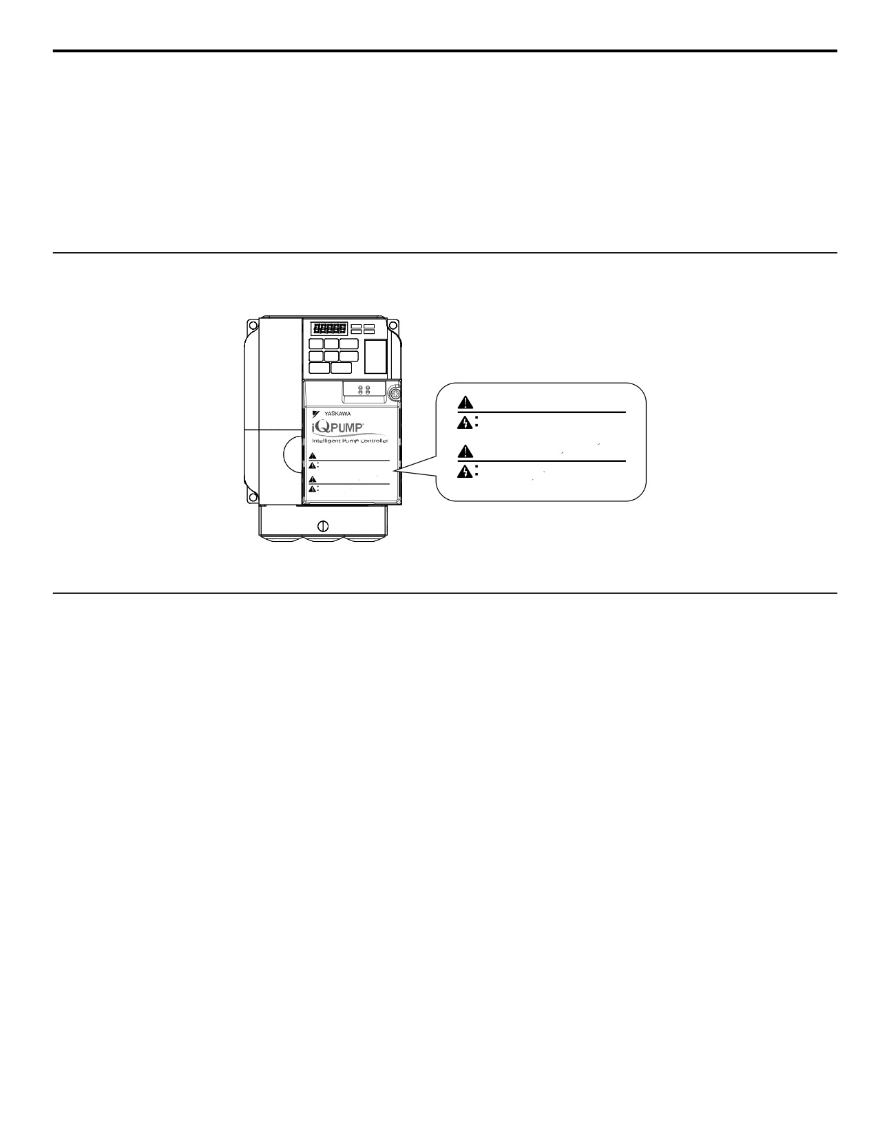
u Drive Label Warning Example
Always heed the warning information listed in Figure i.3.
WARNING
Risk of electric shock.
Read manual before installing.
Wait 5 minutes for capacitor discharge after
Micro
disconnecting power supply.
Risque de decharge
WARNING
Risk of electric shock.
AVERTISSEMENT
electrique.
Read manual before installing.
disconnecting power supply.
Wait 5 minutes for capacitor discharge after
Lire le manuel avant l'installation.
Risque de decharge
Attendre 5 minutes apres la coupure de l'alimentation,
AVERTISSEMENT
electrique.
pour permettre la decharge des condensateurs.
Lire le manuel avant l'installation.
pour permettre la decharge des condensateurs.
Attendre 5 minutes apres la coupure de l'alimentation,
Figure i.3 Warning Information Example
u Warranty Information
n Restrictions
The drive is not designed or manufactured for use in devices or systems that may directly affect or threaten human lives or
health.
Customers who intend to use the product described in this manual for devices or systems relating to transportation, health
care, space aviation, atomic power, electric power, or in underwater applications must first contact their Yaskawa
representatives or the nearest Yaskawa sales office.
WARNING! Injury to Personnel. This product has been manufactured under strict quality-control guidelines. However, if this product is to
be installed in any location where failure of this product could involve or result in a life-and-death situation or loss of human life or in a facility
where failure may cause a serious accident or physical injury, safety devices must be installed to minimize the likelihood of any accident.
19
i.2 General Safety
This Page Intentionally Blank
20
1
Receiving
This chapter explains how to inspect the drive upon receipt, and gives an overview of the different
enclosure types and components.
1.1
SECTION SAFETY
22
1.2
MODEL NUMBER AND NAMEPLATE CHECK
23
21
1.1 Section Safety
1.1
Section Safety
CAUTION
Do not carry the drive by the front cover.
Failure to comply may cause the main body of the drive to fall, resulting in minor or moderate injury.
NOTICE
Observe proper electrostatic discharge procedures (ESD) when handling the drive and circuit boards.
Failure to comply may result in ESD damage to the drive circuitry.
A motor connected to a PWM drive may operate at a higher temperature than a utility-fed motor and the operating
speed range may reduce motor cooling capacity.
Ensure that the motor is suitable for drive duty and/or the motor service factor is adequate to accommodate the additional
heating with the intended operating conditions.
22
1.2 Model Number and Nameplate Check
1.2
Model Number and Nameplate Check
Please perform the following tasks after receiving the drive:
• Inspect the drive for damage.
If the drive appears damaged upon receipt, contact the shipper immediately.
• Verify receipt of the correct model by checking the information on the nameplate.
• If you have received the wrong model or the drive does not function properly, contact your supplier.
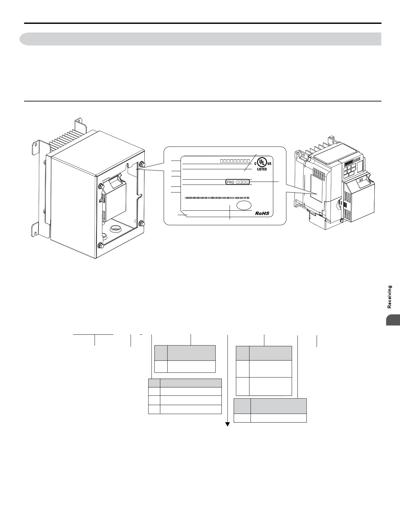
u Nameplate
A
I
MODEL
:
CIMR-PW
MAX APPLI. MOTOR : 0.75kW / 0.4kW REV : A
H
INPUT
: AC3PH 200-240V 50 / 60Hz 2.7A
IND.CONT.EQ.
G
OUTPUT
: AC3PH 0-240V 0-400Hz 1.2A / 0.8A
7J48
MASS
: 0.6 kg
B
F
O / N
:
E
S / N
:
FILE NO
: E131457
IP20
PASS
MADE IN JAPAN
D YA2-1 Kurosaki-shiroishi, Yahatanishi-Ku, Kitakyushu 806-0004 Japan
C
A - Normal Duty Amps
F - Lot number
B - Software version
G-Output specifications
C - Enclosure type
H - Input specifications
D - Address <1>
I
- AC drive model
E - Serial number
Figure 1.1 Nameplate Information Example
<1> The address of the head office of Yaskawa Electric Corporation (responsible for product liability) is shown on the nameplate.
1
CIMR
-P W
2
V
0010
F A A
Drive
iQpump
Customized
Enclosure
No.
Design
No.
Specifications
Type <1>
Revision
V
Standard model
IP20/NEMA 1
Order
F
UL Type 1
No.
Voltage Class
IP66/NEMA 4X
G
B
1-phase, 200-240 Vac
UL Type 4X
2
3-phase, 200-240 Vac
Environmental
No.
4
3-phase, 380-480 Vac
Specification <2>
A
Standard
Refer to the following tables
<1> Refer to Mechanical Installation on page 28 for differences regarding enclosure protection types and component
descriptions.
<2> Please contact Yaskawa for details regarding Environmental Specifications.
23
1.2
Model Number and Nameplate Check
n
Single-Phase 200 V Class
Drive Model
Max. Motor Capacity kW (HP)
Rated Output Current A
BV0006
1.1 (1)
6.0
BV0010
2.2 (3)
9.6
BV0012
3.0 (3)
12.0
BV0018
3.7 (5)
17.5
n
Three-Phase 200 V Class
Drive Model
Max. Motor Capacity kW (HP)
Rated Output Current A
2V0006
1.1
(1.5)
6.0
2V0010
2.2 (3)
9.6
2V0012
3.0 (3)
12.0
2V0020
5.5 (5)
19.6
2V0030
7.5 (10)
30.0
2V0040
11 (10)
40.0
2V0056
15 (20)
56.0
2V0069
18.5 (25)
69.0
n
Three-Phase 400 V Class
Drive Model
Max. Motor Capacity kW (HP)
Rated Output Current A
4V0002
0.75 (1)
2.1
4V0004
1.5 (2)
4.1
4V0005
2.2 (3)
5.4
4V0007
3.0 (3)
6.9
4V0009
3.7 (5)
8.8
4V0011
5.5
(7.5)
11.1
4V0018
7.5 (10)
17.5
4V0023
11 (15)
23.0
4V0031
15 (20)
31.0
4V0038
18.5 (25)
38.0
24
2
Mechanical Installation
This chapter explains how to properly mount and install the drive.
2.1
SECTION SAFETY
26
2.2
MECHANICAL INSTALLATION
28
25
2.1 Section Safety
2.1
Section Safety
WARNING
Fire Hazard
Provide sufficient cooling when installing the drive inside an enclosed panel or cabinet.
Failure to comply could result in overheating and fire.
When multiple drives are placed inside the same enclosure panel, install proper cooling to ensure air entering the enclosure
does not exceed 40 °C.
CAUTION
Crush Hazard
Do not carry the drive by the front cover.
Failure to comply may result in minor or moderate injury from the main body of the drive falling.
NOTICE
Observe proper electrostatic discharge (ESD) procedures when handling the drive.
Failure to comply could result in ESD damage to the drive circuitry.
It may be difficult to perform maintenance on the cooling fans of drives installed in a vertical row inside an enclosure.
Ensure adequate spacing at the top of the drive to perform cooling fan replacement when required.
Operating the motor in the low-speed range diminishes the cooling effects, increases motor temperature, and may
lead to motor damage by overheating.
Reduce the motor torque in the low-speed range whenever using a standard blower cooled motor. If 100% torque is required
continuously at low speed, consider using a special drive or vector motor. Select a motor that is compatible with the required
load torque and operating speed range.
Do not operate motors above the maximum rated RPM.
Failure to comply may lead to bearing or other mechanical motor failures.
The speed range for continuous operation differs according to the lubrication method and motor manufacturer.
If the motor is to be operated at a speed higher than the rated speed, consult with the manufacturer.
Continuously operating an oil-lubricated motor in the low-speed range may result in burning.
26
2.1 Section Safety
NOTICE
When the wiring distance is greater than 100 meters, pay special attention to the motor insulation voltage or use a
drive-rated motor.
Failure to comply could lead to motor winding failure.
Motor vibration may increase when operating a machine in variable-speed mode, if that machine previously operated
at a constant speed.
Install vibration-proof rubber on the motor base or use the frequency jump function to skip a frequency resonating the
machine.
The motor may require more acceleration torque with drive operation than with a commercial power supply.
Set a proper V/f pattern by checking the load torque characteristics of the machine to be used with the motor.
The rated input current of submersible motors is higher than the rated input current of standard motors.
Select an appropriate drive according to its rated output current. When the distance between the motor and drive is long, use
a cable thick enough to connect the motor to the drive to prevent motor torque reduction.
When using an explosion-proof motor, it must be subject to an explosion-proof test in conjunction with the drive.
This is also applicable when an existing explosion-proof motor is to be operated with the drive. Since the drive itself is not
explosion-proof, always install it in a safe place. Be sure to set A1-02 to “0” when using an explosion-proof motor.
Do not use a drive for a single-phase motor.
Replace the motor with a three-phase motor.
If an oil-lubricated gearbox or speed reducer is used in the power transmission mechanism, oil lubrication will be
affected when the motor operates only in the low speed range.
The power transmission mechanism will make noise and experience problems with service life and durability if the motor
is operated at a speed higher than the rated speed.
2
27
2.2 Mechanical Installation
2.2
Mechanical Installation
This section outlines specifications, procedures, and environment for proper mechanical installation of the drive.
u Installation Environment
To help prolong the optimum performance life of the drive, install the drive in the proper environment. Table 2.1 describes
the appropriate environment for the drive.
Table 2.1 Installation Environment
Environment
Conditions
Installation Area
Indoors
IP20/NEMA 1, UL Type 1 enclosure: -10 °C to +40 °C (14 °F to 104 °F)
IP66/NEMA 4X, UL Type 4X enclosure: -10 °C to +40 °C (14 °F to 104 °F)
Drive reliability improves in environments without wide temperature fluctuations.
Ambient Temperature
When using an enclosure panel, install a cooling fan or air conditioner in the area to ensure that the air temperature inside
the enclosure does not exceed the specified levels.
Do not allow ice to develop on the drive.
Humidity
95% RH or less and free of condensation
Storage Temperature
-20 °C to +60 °C (-4 °F to +104 °F)
Install the drive in an area free from:
• oil mist and dust
• metal shavings, oil, water or other foreign materials
• radioactive materials
• combustible materials (e.g., wood)
• harmful gases and liquids
• excessive vibration
• chlorides
Surrounding Area
• direct sunlight
For IP66/NEMA 4X, UL Type 4X enclosure drives, install the drive in an environment suitable for IP66/NEMA 4X, UL
Type 4X enclosures:
• NEMA 4X, UL Type 4X - Enclosures constructed for either indoor or outdoor use to provide a degree of protection
to personnel against incidental contact with the enclosed equipment; to provide a degree of protection against falling
dirt, rain, sleet, snow, windblown dust, splashing water, hose-directed water, and corrosion; and that will be undamaged
by the external formation of ice on the enclosure.
• IP66 - Dust-tight enclosures to not allow any dust to penetrate. The enclosure guards the drive against powerful jetting
water sprayed from any direction and is protected against access to hazardous parts with a wire.
Altitude
Up to 1000 meters without derating; up to 3000 meters with output current, ambient temperature, and voltage derating.
2
10 to 20 Hz at 9.8 m/s
Vibration
20 to 55 Hz at 5.9 m/s2
Orientation
Install the drive vertically to maintain maximum cooling effects.
NOTICE: Prevent foreign matter such as metal shavings or wire clippings from falling into the drive during installation and project
construction. Failure to comply could result in damage to the drive. Place a temporary cover over the top of the drive during installation.
Remove the temporary cover before startup, as the cover will reduce ventilation and cause the drive to overheat.
NOTICE: Avoid placing drive peripheral devices, transformers, or other electronics near the drive. Failure to comply could result in erroneous
operation. If such devices must be used in close proximity to the drive, take proper steps to shield the drive from noise.
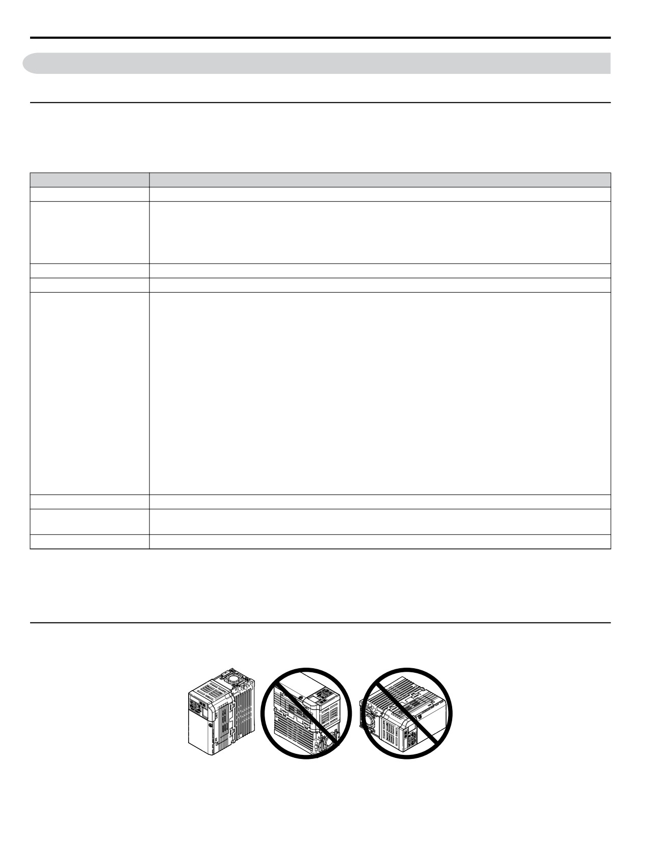
u Installation Orientation and Spacing
NOTICE: Install the drive upright as illustrated in Figure 2.1. Failure to comply may damage the drive due to improper cooling.
Figure 2.1 Correct Installation Orientation
28
2.2 Mechanical Installation
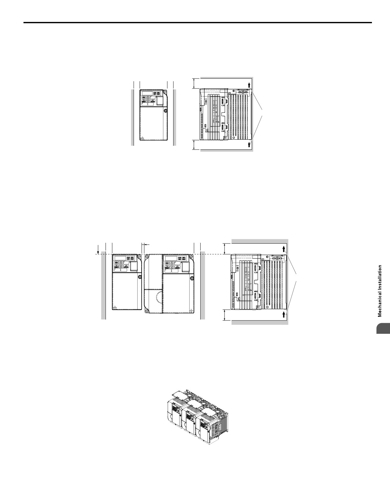
n Single Drive Installation
Figure 2.2 shows the required installation spacing to maintain sufficient space for airflow and wiring for IP20/NEMA 1, UL
Type 1 and IP66/NEMA 4X, UL Type 4X enclosures. Install the heatsink against a closed surface to avoid diverting cooling
air around the heatsink.
Side Clearance
Top/Bottom Clearance
A
A
C
B
C
A - 30 mm minimum
C - 100 mm minimum
B - Airflow direction
Figure 2.2 Correct Installation Spacing
Note:
IP20/NEMA 1, UL Type 1 and IP66/NEMA 4X, UL Type 4X enclosure models require the same amount of space above and below the
drive for installation.
n Multiple Drive Installation
When installing multiple drives into the same enclosure panel, mount the drives according to Figure 2.2. When mounting
drives with a minimum side-by-side clearance of 2 mm according to Figure 2.3, derating must be considered and parameter
L8-35 must be set.
A B
2 mm
B
C
D
C
A - Line up the tops of the drives.
C - 100 mm minimum
2
B - 30 mm minimum
D - Airflow direction
Figure 2.3 Space Between Drives (Side-by-Side Mounting)
Note:
When installing drives of different heights in the same enclosure panel, the tops of the drives should line up. Leave space between the top
and bottom of stacked drives for cooling fan replacement if required. Using this method, it is possible to replace the cooling fans later.
NOTICE: When mounting IP20/NEMA 1, UL Type 1 enclosure drives side by side, the top covers of all drives must be removed as shown
in Figure 2.4.
Figure 2.4 IP20/NEMA 1, UL Type 1 Side-by-Side Mounting in Enclosure
29
2.2 Mechanical Installation
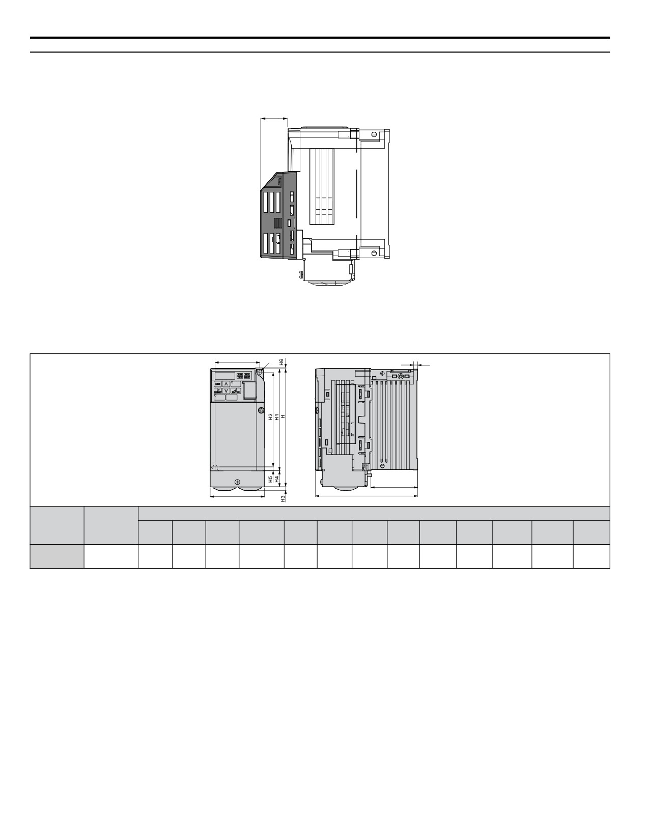
u Exterior and Mounting Dimensions
The installed 24 V power supply option adds 27 mm (1.06 in.) to the total depth of IP20/NEMA 1, UL Type 1 enclosure drives.
Height and width dimensions are unaffected.
27 mm (1.06 in.)
Figure 2.5 24 V Power Supply Dimensions
n IP20/NEMA 1, UL Type 1 Enclosure Dimensions
Table 2.2 Dimensions for IP20/NEMA 1, UL Type 1 Enclosure Drives
W1
2-M4
t1
D1
W
D
Dimensions mm (in)
Voltage
Drive Model
Wt.
Class
W
H
D <1>
W1
H1
H2
H3
H4
H5
H6
D1
t1
kg (lb.)
Three-Phase
68
149.5
128
56
128
118
4
20
5
1.5
58.5
5
1.3
2V0006F
200 V Class
(2.68)
(5.89)
(5.04)
(2.20)
(5.03)
(4.65)
(0.16)
(0.79)
(0.20)
(0.06)
(2.32)
(0.20)
(2.9)
<1> The installed 24 V power supply option adds 27 mm (1.06 in.) to the total depth of the drive.
30
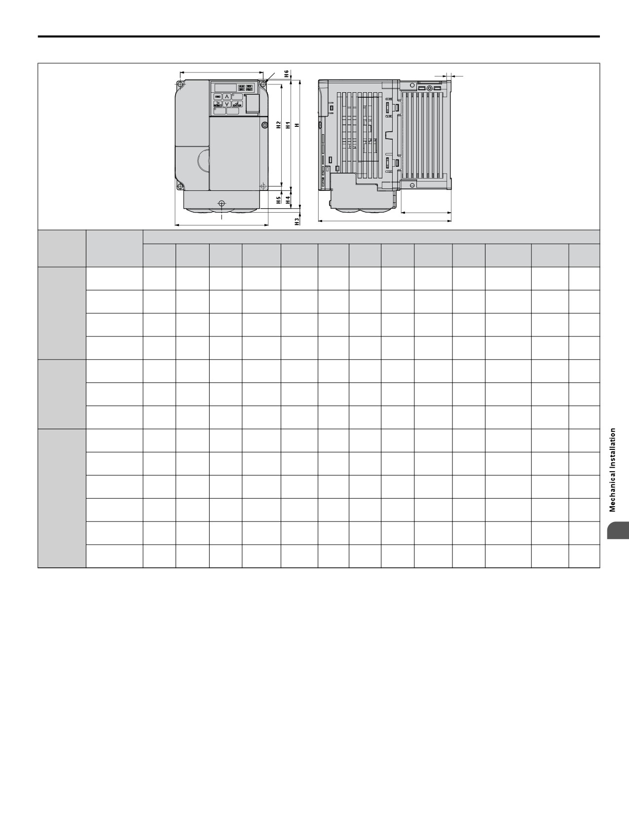
2.2 Mechanical Installation
Table 2.3 Dimensions for IP20/NEMA 1, UL Type 1 Enclosure Drives
W1
4-M4
t1
D1
D
W
Dimensions mm (in)
Voltage
Drive Model
Wt.
Class
W
H
D <1>
W1
H1
H2
H3
H4
H5
H6
D1
t1
kg (lb.)
108
149.5
137.5
96
128
118
4
20
5
1.5
58
5
1.9
BV0006F
(4.25)
(5.89)
(5.41)
(3.78)
(5.03)
(4.65)
(0.16)
(0.79)
(0.20)
(0.06)
(2.28)
(0.20)
(4.2)
108
149.5
154
96
128
118
4
20
5
1.5
58
5
2.0
Single-
BV0010F
(4.25)
(5.89)
(6.06)
(3.78)
(5.03)
(4.65)
(0.16)
(0.79)
(0.20)
(0.06)
(2.28)
(0.20)
(4.4)
Phase
200 V Class
140
153
163
128
128
118
4.8
20
5
5
65
5
2.6
BV0012F
(5.51)
(6.02)
(6.42)
(5.04)
(5.03)
(4.65)
(0.19)
(0.79)
(0.20)
(0.20)
(2.56)
(0.20)
(5.7)
170
171
180
158
133
118
4.8
38
5
5
65
5
3.3
BV0018F
(6.69)
(6.73)
(7.08)
(6.22)
(5.23)
(4.64)
(0.19)
(1.50)
(0.20)
(0.20)
(2.56)
(0.20)
7.3
108
149.5
129
96
128
118
4
20
5
1.5
58
5
1.9
2V0010F
(4.25)
(5.89)
(5.08)
(3.78)
(5.03)
(4.65)
(0.16)
(0.79)
(0.20)
(0.06)
(2.28)
(0.20)
(4.2)
Three-
108
149.5
137.5
96
128
118
4
20
5
1.5
58
5
1.9
Phase
2V0012F
(4.25)
(5.89)
(5.41)
(3.78)
(5.03)
(4.65)
(0.16)
(0.79)
(0.20)
(0.06)
(2.28)
(0.20)
(4.2)
200 V Class
140
153
143
128
128
118
4.8
20
5
5
65
5
2.6
2V0020F
(5.51)
(6.02)
(5.63)
(5.04)
(5.03)
(4.65)
(0.19)
(0.79)
(0.20)
(0.20)
(2.56)
(0.20)
(5.7)
108
149.5
99
96
128
118
4
20
5
1.5
28
5
1.4
4V0002F
(4.25)
(5.89)
(3.90)
(3.78)
(5.03)
(4.65)
(0.16)
(0.79)
(0.20)
(0.06)
(1.10)
(0.20)
(3.1)
108
149.5
137.5
96
128
118
4
20
5
1.5
58
5
1.9
4V0004F
(4.25)
(5.89)
(5.41)
(3.78)
(5.03)
(4.65)
(0.16)
(0.79)
(0.20)
(0.06)
(2.28)
(0.20)
(4.2)
108
149.5
154
96
128
118
4
20
5
1.5
58
5
1.9
Three-
4V0005F
(4.25)
(5.89)
(6.06)
(3.78)
(5.03)
(4.65)
(0.16)
(0.79)
(0.20)
(0.06)
(2.28)
(0.20)
(4.2)
Phase
400 V Class
108
149.5
154
96
128
118
4
20
5
1.5
58
5
1.9
4V0007F
(4.25)
(5.89)
(6.06)
(3.78)
(5.03)
(4.65)
(0.16)
(0.79)
(0.20)
(0.06)
(2.28)
(0.20)
(4.2)
108
149.5
154
96
128
118
4
20
5
1.5
58
5
1.9
4V0009F
2
(4.25)
(5.89)
(6.06)
(3.78)
(5.03)
(4.65)
(0.16)
(0.79)
(0.20)
(0.06)
(2.28)
(0.20)
(4.2)
140
153
143
128
128
118
4.8
20
5
5
65
5
2.6
4V0011F
(5.51)
(6.02)
(5.63)
(5.04)
(5.03)
(4.65)
(0.19)
(0.79)
(0.20)
(0.20)
(2.56)
(0.20)
(5.7)
<1> The installed 24 V power supply option adds 27 mm (1.06 in.) to the total depth of the drive.
31
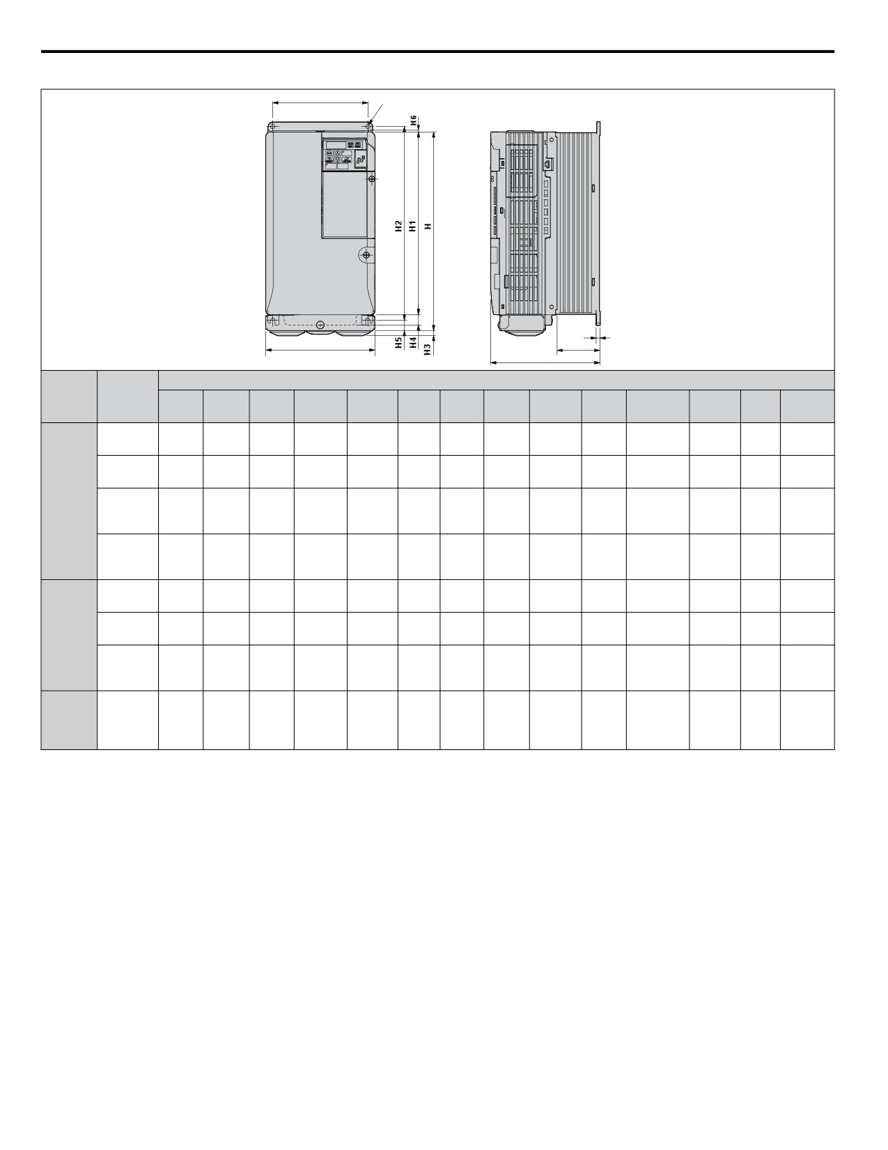
2.2 Mechanical Installation
Table 2.4 Dimensions for IP20/NEMA 1, UL Type 1 Enclosure Drives
W1
4-d
t1
W
D1
D
Dimensions mm (in)
Voltage
Drive
Wt.
Class
Model
W
H
D <1>
W1
H1
H2
H3
H4
H5
H6
D1
t1
d
kg (lb.)
140
254
140
122
234
248
6
13
13
1.5
55
5
3.8
2V0030F
M5
(5.51)
(10.00)
(5.51)
(4.80)
(9.21)
(9.76)
(0.24)
(0.51)
(0.51)
(0.06)
(2.17)
(0.20)
(8.4)
140
254
140
122
234
248
6
13
13
1.5
55
5
3.8
2V0040F
M5
Single-
(5.51)
(10.00)
(5.51)
(4.80)
(9.21)
(9.76)
(0.24)
(0.51)
(0.51)
(0.06)
(2.17)
(0.20)
(8.4)
Phase
284
200 V
180
290
163
160
270
6
15
13
1.5
75
5
5.5
2V0056F
(11.18
M5
Class
(7.09)
(11.42)
(6.42)
(6.30)
(10.63)
(0.24)
(0.59)
(0.51)
(0.06)
(2.95)
(0.20)
(12.1)
)
336
220
350
187
192
320
7
15
22
1.5
78
5
9.2
2V0069F
(13.23
M6
(8.66)
(13.78)
(7.36)
(7.56)
(12.60)
(0.28)
(0.59)
(0.87)
(0.06)
(3.07)
(0.20)
(20.3)
)
140
254
140
122
234
248
6
13
13
1.5
55
5
3.8
4V0018F
M5
(5.51)
(10.00)
(5.51)
(4.80)
(9.21)
(9.76)
(0.24)
(0.51)
(0.51)
(0.06)
(2.17)
(0.20)
(8.4)
Three-
140
254
140
122
234
248
6
13
13
1.5
55
5
3.8
Phase
4V0023F
M5
(5.51)
(10.00)
(5.51)
(4.80)
(9.21)
(9.76)
(0.24)
(0.51)
(0.51)
(0.06)
(2.17)
(0.20)
(8.4)
200 V
Class
284
180
290
143
160
270
6
15
13
1.5
55
5
5.2
4V0031F
(11.18
M5
(7.09)
(11.42)
(5.63)
(6.30)
(10.63)
(0.24)
(0.59)
(0.51)
(0.06)
(2.17)
(0.20)
(11.5)
)
Three-
284
Phase
180
290
163
160
270
6
13
13
1.5
75
5
5.5
4V0038F
(11.18
M5
400 V
(7.09)
(11.42)
(6.42)
(6.30)
(10.63)
(0.24)
(0.51)
(0.51)
(0.06)
(2.95)
(0.20)
(12.1)
)
Class
<1> The installed 24 V power supply option adds 27 mm (1.06 in.) to the total depth of the drive.
32
2.2 Mechanical Installation
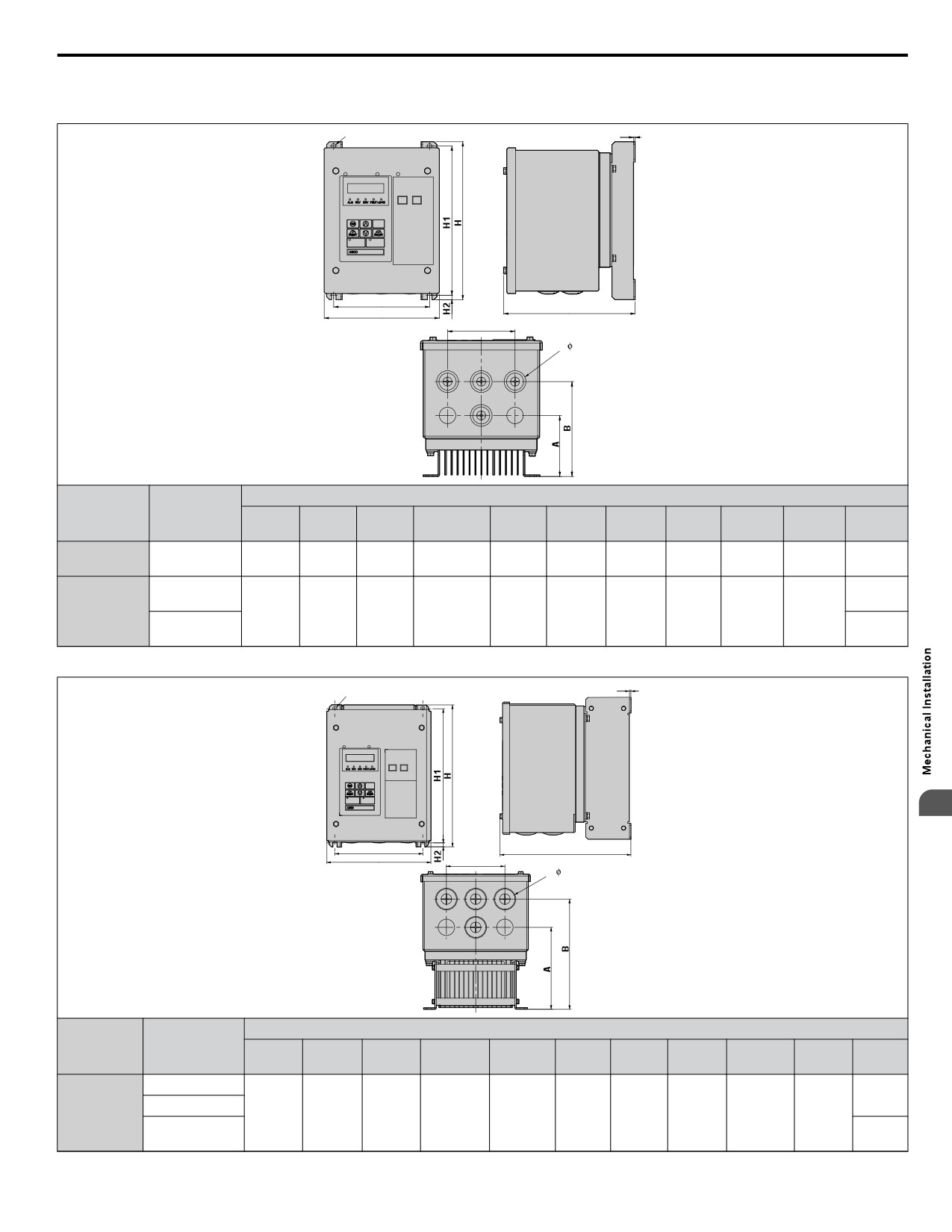
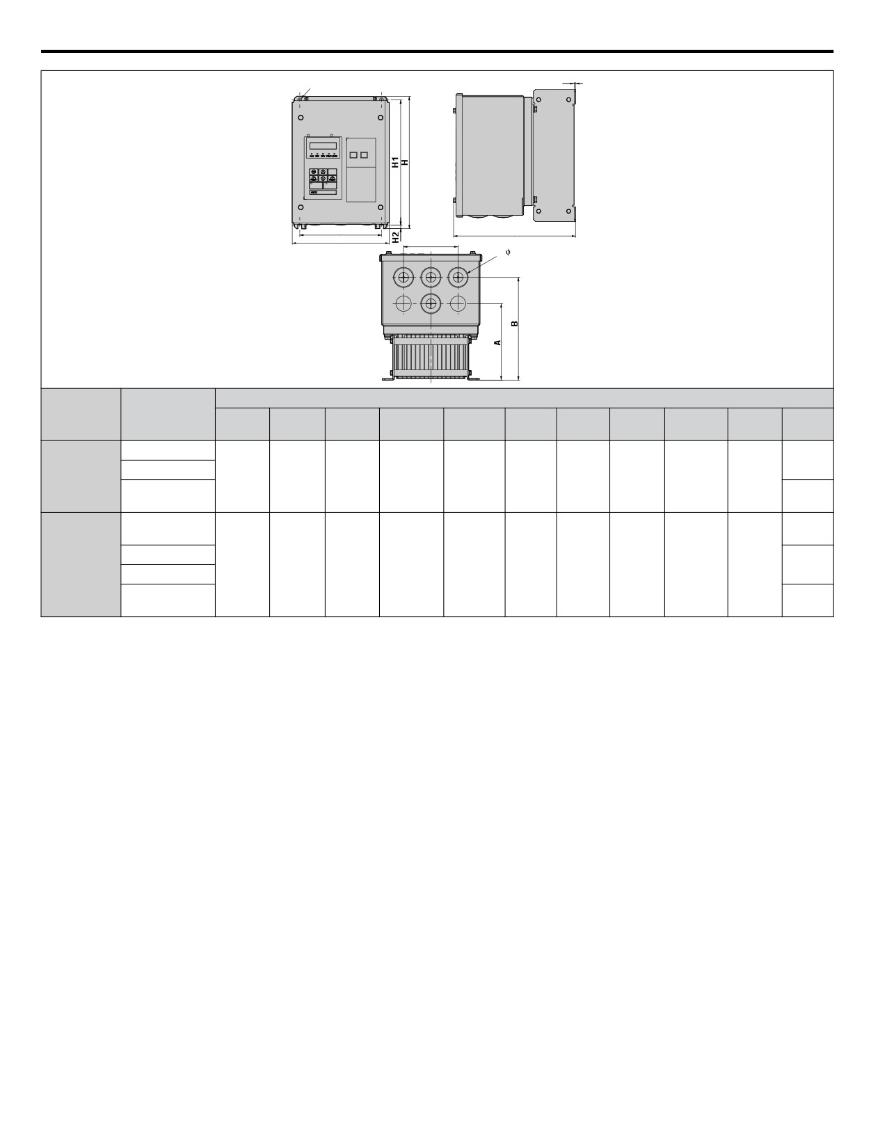
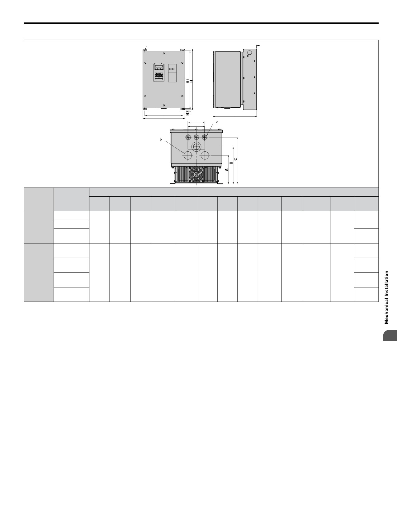
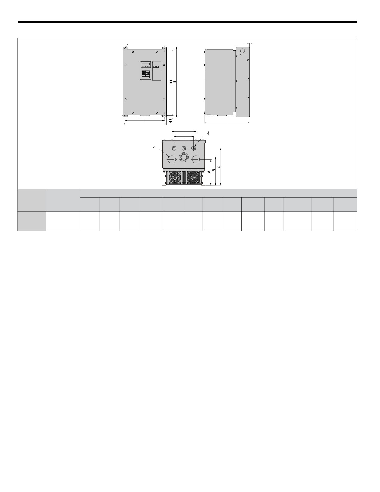
n IP66/NEMA 4X, UL Type 4X Enclosure Dimensions
Table 2.5 Dimensions for IP66/NEMA 4X, UL Type 4X Enclosure Drives
4-M5
t1
W1
D
W
E
6- 22
Dimensions mm (in)
Voltage Class
Drive Model
Wt.
W
H
D
W1
H1
H2
t1
A
B
E
kg (lb.)
Three-Phase
162
222
185
135
210
6
2
81
126
90
4.8
2V0006G
200 V Class
(6.38)
(8.74)
(7.28)
(5.32)
(8.27)
(0.24)
(0.08)
(3.19)
(4.96)
(3.54)
(10.58)
5.0
4V0002G
(11.02)
Three-Phase
162
222
185
135
210
6
2
81
126
90
400 V Class
(6.38)
(8.74)
(7.28)
(5.32)
(8.27)
(0.24)
(0.08)
(3.19)
(4.96)
(3.54)
5.1
4V0004G
(11.24)
Table 2.6 Dimensions for IP66/NEMA 4X, UL Type 4X Enclosure Drives
t1
4-M6
2
W1
D
W
E
6- 28
Dimensions mm (in)
Voltage Class
Drive Model
Wt.
W
H
D
W1
H1
H2
t1
A
B
E
kg (lb.)
BV0006G
7.8
Single-Phase
BV0010G
187
255
235
158
241
7
2.5
140
188
100
(17.2)
200 V Class
(7.36)
(10.04)
(9.25)
(6.22)
(9.49)
(0.28)
(0.10)
(5.51)
(7.40)
(3.94)
8.2
BV0012G
(18.08)
33
2.2 Mechanical Installation
t1
4-M6
W1
D
W
E
6- 28
Dimensions mm (in)
Voltage Class
Drive Model
Wt.
W
H
D
W1
H1
H2
t1
A
B
E
kg (lb.)
2V0010G
7.7
Three-Phase
2V0012G
187
255
235
158
241
7
2.5
140
188
100
(16.98)
200 V Class
(7.36)
(10.04)
(9.25)
(6.22)
(9.49)
(0.28)
(0.10)
(5.51)
(7.40)
(3.94)
8.1
2V0020G
(17.86)
7.7
4V0005G
(16.98)
Three-Phase
4V0007G
187
255
235
158
241
7
2.5
140
188
100
7.9
400 V Class
4V0009G
(7.36)
(10.04)
(9.25)
(6.22)
(9.49)
(0.28)
(0.10)
(5.51)
(7.40)
(3.94)
(17.42)
8.1
4V0011G
(17.86)
34
2.2 Mechanical Installation
Table 2.7 Dimensions for IP66/NEMA 4X, UL Type 4X Enclosure Drives
4-M6
t1
W1
D
W
F
3- 22
E
3- 44
Dimensions mm (in)
Voltage
Drive Model
Wt.
Class
W
H
D
W1
H1
H2
t1
A
B
C
E
F
kg (lb.)
2V0030G
21.8
Three-
(48.06)
2V0040G
290
420
305
265
400
8.5
2.5
158
205.5
258
90
95
Phase
(11.42)
(16.54)
(12.01)
(10.43)
(15.75)
(0.33)
(0.10)
(6.22)
(8.09)
(10.16)
(3.54)
(3.74)
200 V Class
23.2
2V0056G
(51.15)
21.7
4V0018G
(47.84)
21.8
Three-
4V0023G
290
420
305
265
400
8.5
2.5
158
205.5
258
90
95
(48.06)
Phase
(11.42)
(16.54)
(12.01)
(10.43)
(15.75)
(0.33)
(0.10)
(6.22)
(8.09)
(10.16)
(3.54)
(3.74)
22.9
400 V Class
4V0031G
(50.49)
23.2
4V0038G
(51.15)
2
35
2.2 Mechanical Installation
Table 2.8 Dimensions for IP66/NEMA 4X, UL Type 4X Enclosure Drives
4-M6
t1
W1
D
W
F
3- 22
E
3- 50
Dimensions mm (in)
Voltage
Drive Model
Class
Wt.
W
H
D
W1
H1
H2
t1
A
B
C
E
F
kg (lb.)
Three-
290
465
305
265
445
8.5
2.5
173
188
248
130
160
27.7
Phase
2V0069G
(11.42)
(18.31)
(12.01)
(10.43)
(17.52)
(0.33)
(0.10)
(6.81)
(7.40)
(9.76)
(5.12)
(6.30)
(61.07)
200 V Class
36
3
Electrical Installation
This chapter explains proper procedures for wiring the control circuit terminals, motor and power
supply.
3.1
SECTION SAFETY
38
3.2
STANDARD CONNECTION DIAGRAM
40
3.3
TERMINAL BLOCK CONFIGURATION
44
3.4
PROTECTIVE COVERS
45
3.5
PREPARING IP66/NEMA 4X, UL TYPE 4X ENCLOSURE DRIVES FOR
WIRING
47
3.6
MAIN CIRCUIT WIRING
50
3.7
CONTROL CIRCUIT WIRING
55
3.8
I/O CONNECTIONS
59
3.9
MAIN FREQUENCY REFERENCE
61
3.10
WIRING CHECKLIST
62
37
3.1 Section Safety
3.1
Section Safety
DANGER
Electrical Shock Hazard
Do not connect or disconnect wiring while the power is on.
Failure to comply will result in death or serious injury.
WARNING
Electrical Shock Hazard
Do not operate equipment with covers removed.
Failure to comply could result in death or serious injury.
The diagrams in this section may show drives without covers or safety shields to show details. Be sure to reinstall covers or
shields before operating the drives and run the drives according to the instructions described in this manual.
Always ground the motor-side grounding terminal.
Improper equipment grounding could result in death or serious injury by contacting the motor case.
Do not perform work on the drive while wearing loose clothing, jewelry or without eye protection.
Failure to comply could result in death or serious injury.
Remove all metal objects such as watches and rings, secure loose clothing, and wear eye protection before beginning work
on the drive.
Do not remove covers or touch circuit boards while the power is on.
Failure to comply could result in death or serious injury.
Do not allow unqualified personnel to perform work on the drive.
Failure to comply could result in death or serious injury.
Installation, maintenance, inspection, and servicing must be performed only by authorized personnel familiar with
installation, adjustment, and maintenance of AC drives.
Do not touch any terminals before the capacitors have fully discharged.
Failure to comply could result in death or serious injury.
Before wiring terminals, disconnect all power to the equipment. The internal capacitor remains charged even after the power
supply is turned off. The charge indicator LED will extinguish when the DC bus voltage is below 50 Vdc. To prevent electric
shock, wait at least five minutes after all indicators are off and measure the DC bus voltage level to confirm safe level.
Fire Hazard
Tighten all terminal screws to the specified tightening torque.
Loose electrical connections could result in death or serious injury by fire due to overheating of electrical connections.
Do not use improper combustible materials.
Failure to comply could result in death or serious injury by fire.
Attach the drive to metal or other noncombustible material.
Do not use an improper voltage source.
Failure to comply could result in death or serious injury by fire.
Verify that the rated voltage of the drive matches the voltage of the incoming power supply before applying power.
Always use a thermal overload relay or an over-temperature contact when using a braking resistor.
Failure to comply could result in death or serious injury by fire.
Power to the drive should be interrupted when the relay is triggered.
38
3.1 Section Safety
NOTICE
Observe proper electrostatic discharge procedures (ESD) when handling the drive and circuit boards.
Failure to comply may result in ESD damage to the drive circuitry.
Never connect or disconnect the motor from the drive while the drive is outputting voltage.
Improper equipment sequencing could result in damage to the drive.
Do not use unshielded cable for control wiring.
Failure to comply may cause electrical interference resulting in poor system performance. Use shielded, twisted-pair wires
and ground the shield to the ground terminal of the drive.
Check all the wiring to ensure that all connections are correct after installing the drive and connecting any other
devices.
Failure to comply could result in damage to the drive.
Do not modify the drive circuitry.
Failure to comply could result in damage to the drive and will void warranty.
Yaskawa is not responsible for any modification of the product made by the user. This product must not be modified.
Route motor leads U/T1, V/T2, and W/T3 separate from other leads to reduce possible interference-related issues.
Failure to comply may result in abnormal operation of drive and nearby equipment.
3
39
3.2 Standard Connection Diagram
3.2
Standard Connection Diagram
Connect the drive and peripheral devices as shown in Figure 3.1. It is possible to run the drive via the digital operator without
connecting digital I/O wiring. This section does not discuss drive operation; Refer to Start-Up Programming & Operation
on page 63 for instructions on operating the drive.
NOTICE: Inadequate branch short circuit protection could result in damage to the drive. Install adequate branch circuit short circuit protection
per applicable codes. The drive is suitable for circuits capable of delivering not more than 31,000 RMS symmetrical amperes, 240 Vac
maximum (200 V Class) and 480 Vac maximum (400 V Class).
NOTICE: When the wiring distance is greater than 100 meters, pay special attention to the motor insulation voltage or use a drive duty
motor. Failure to comply could lead to motor insulation breakdown.
NOTICE: Correctly set Sink/Source jumper S3 for internal power supply. Failure to comply may result in damage to the drive. Refer to I/O
Connections on page 59 for details.
NOTICE: Do not connect AC control circuit ground to drive enclosure. Improper drive grounding can cause control circuit malfunction.
NOTICE: Route motor leads U/T1, V/T2, and W/T3 separate from all other leads to reduce possible interference related issues. Failure to
comply may result in abnormal operation of drive and nearby equipment.
NOTICE: The minimum load for the multi-function relay output MA-MB-MC is 10 mA. If a circuit requires less than 10 mA (reference value),
connect it to a photocoupler output (P1, P2, PC). Improper application of peripheral devices could result in damage to the photocoupler
output of the drive.
40
//////////////////////////////////////////