Yaskawa iQpump Micro AC Drive Compact Intelligent Pump Controller. User Manual (2014) - page 2
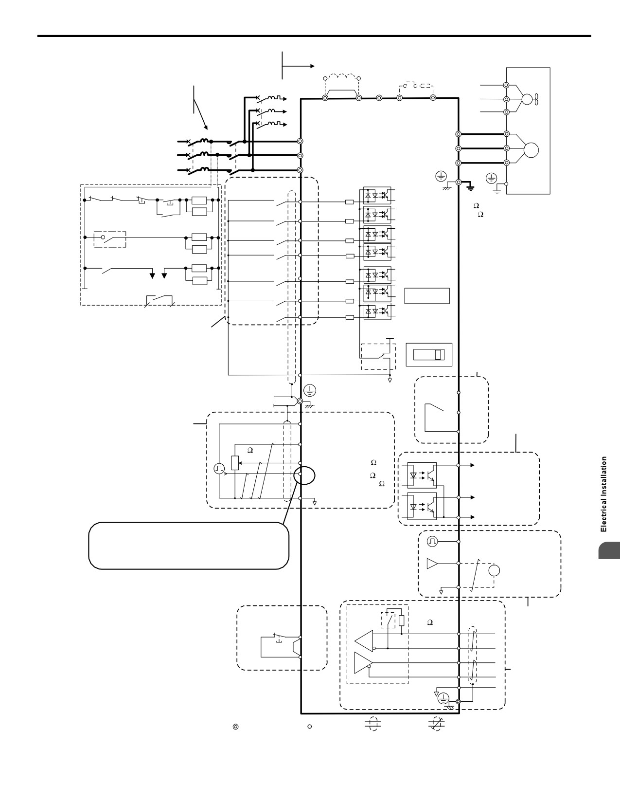
3.2 Standard Connection Diagram
Terminals +1, +2, − , B1, and B2
DC link choke
<2>
are for connecting options.
(option)
Motor
<1>
Thermal relay
Never connect power supply
Braking resistor
(option)
Cooling fan
lines to these terminals.
(option)
FU
<3>
Jumper
r1
For single-phase
2 MCCB
FV
200 V power supply
r1
s1
M
-
use R/L1 and S/L2.
+2
+1
B1
B2
FW
s1
t1
Wiring sequence should shut off
t1
power to the drive when a fault
iQpumpMicro
U
output is triggered.
1 MCCB
MC
U/T1
<8>
R/L1
R/L1
V
V/T2
M
Three phase S/L2
S/L2
Main circuit
power supply
W
W/T3
for 200 V / 400 V
T/L3
T/L3
Control circuit
<4>
TRX THRX OFF ON
MC
Forward run/stop
S1
Ground
10 or less (400 V class)
SA
100 or less (200 V class)
Braking resistor unit
Not Used
S2
Thermal relay trip contact
External
THRX
pump fault
S3
1
2
SA
Fault reset
S4
MC
TRX
Multi-
setpoint 1
S5
SA
MC MB
TRX
Option card
HAND Mode
S6
connector
Fault relay contact
HAND Mode 2
S7
Digital inputs
+24 V 8 mA
(default setting)
24 V
DIP switch S1
V
I
Digital output
<5>
Sink
250 Vac, 10 mA to 1 A
DIP
30 Vdc, 10 mA to 1 A
switch S3
Source
SC
(default setting)
Shield ground
Fault
0V
MA
terminal
Digital output
MB
System feedback,
5 to 48 Vdc
HAND speed,
Pulse train input
2 to 50 mA
RP
(max. 32 kHz)
MC
Main speed reference
(default setting)
Multi-function
Setting power supply
+V
programmable
2 k
+10.5 max. 20 mA
A1
0 to +10 V (20 k
)
P1
During Run
(photocoupler 1)
A2
0 to +10 V (20 k
)
(0)4 to 20 mA (250
)
Fault
AC
P2
(photocoupler 2)
PC
Photocoupler
output common
Refer to “Transducer 2-Wire Connection Diagram”
MP
Pulse train output
and “Transducer 3-Wire Connection Diagram” figures
<6>
0 to 32 kHz
on the following pages for details on 24 V Power Supply
Analog monitor
3
connections.
AM
output
+
AM
0 to +10 Vdc
AC
- (2 mA)
Termination
DIP
Comm.
Monitor
resistor
connector
output
switch
120
, 1/2 W
Safety switch
S2
R+
Safe Disable
HC
R-
Input
Jumper
<7>
H1
S+
MEMOBUS/
Modbus comm.
S-
RS-485/422
IG
Cable shield ground
main circuit terminal
control terminal
shielded line
twisted-pair shielded line
Figure 3.1 Drive Standard Connection Diagram
41
3.2 Standard Connection Diagram
<1> Remove the jumper when installing an optional DC link choke.
<2> The MC on the input side of the main circuit should open when the thermal relay is triggered.
<3> Self-cooled motors do not require separate cooling fan motor wiring.
<4> Connected using sequence input signal (S1 to S7) from NPN transistor; Default: sink mode (0 V com).
<5> Use only a +24 V internal power supply in sinking mode; the source mode requires an external power supply.
<6> Monitor outputs work with devices such as analog frequency meters, ammeters, voltmeters and wattmeters; they are not
intended for use as a feedback-type of signal.
<7> Disconnect the wire jumper between HC and H1 when utilizing the safety input. Refer to Wiring the Control Circuit
Terminal on page 57 for details on removing the jumper. The wire length for the Safe Disable input should not exceed
30 m.
<8> Note that if the drive is set to trigger a fault output whenever the fault restart function is activated (L5-02 = 1), then a
sequence to interrupt power when a fault occurs will result in shutting off the power to the drive as the drive attempts to restart
itself. The default setting for L5-02 is 0 (fault output active during restart attempt).
WARNING! Sudden Movement Hazard. Do not close the wiring for the control circuit unless the multifunction input terminal parameter is
properly set (S5 for 3-Wire; H1-05 = “0”). Improper sequencing of run/stop circuitry could result in death or serious injury from moving
equipment.
WARNING! Sudden Movement Hazard. Ensure start/stop and safety circuits are wired properly and in the correct state before energizing
the drive. Failure to comply could result in death or serious injury from moving equipment. When programmed for 3-Wire control, a momentary
closure on terminal S1 may cause the drive to start.
WARNING! When 3-Wire sequence is used, set the drive to 3-Wire sequence before wiring the control terminals and ensure parameter
b1-17 is set to 0 (drive does not accept a run command at power up (default). If the drive is wired for 3-Wire sequence but set up for 2-Wire
sequence (default) and if parameter b1-17 is set to 1 (drive accepts a Run command at power up), the motor will rotate in reverse direction
at power up of the drive and may cause injury.
WARNING! When the application preset function is executed (or A1-06 is set to any value other than 0) the drive I/O terminal functions
change. This may cause unexpected operation and potential damage to equipment or injury.
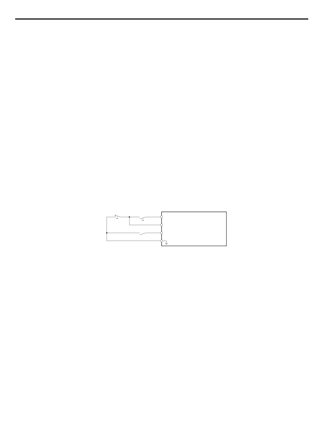
Figure 3.2 illustrates an example of a 3-Wire sequence.
Drive
Stop relay (N.C.) Run relay (N.O.)
S1
Run command (run on momentary close)
S2
Stop command (stop on momentary open)
S5
Forward/reverse command
(multi-function input: H1-05 = 0)
SC
Sequence input common
Figure 3.2 3-Wire Sequence
42
3.2 Standard Connection Diagram
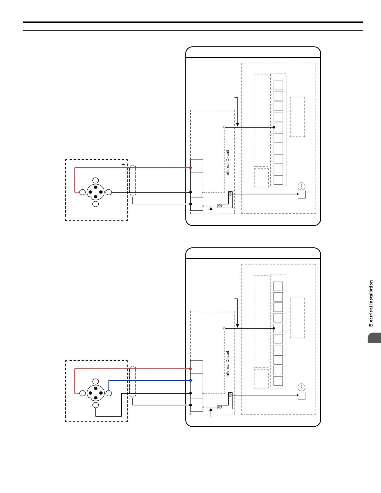
u Transducer Connection Diagrams
iQpump Micro Drive
iQpump Micro Drive
I/O Terminals
TB1-2
P1
Signal Wire (white)
TB1-1
P2
24 V PSU to Drive
PC
TB1-3
24V Power Supply
A1
Example:
J2
A2
Customer supplied
pressure transducer
V+
feedback device
CN1
AC
(2-Wire)
Terminal
Block
AM
24V Power Supply
24V
AC
N/C
Transducer
TB2
4
AC
MP
Signal 4-20 mA
SIG
(typical)
FE
1
3
A2
EG
V+
Output
Functional Earth Cable
Shield
(Earth
2
FE
(Blue)
Ground)
N/C
Internal Circuit
Figure 3.3 Transducer 2-Wire Connection Diagram
iQpump Micro Drive
iQpump Micro Drive
I/O Terminals
TB1-2
P1
Signal Wire (white)
TB1-1
P2
24 V PSU to Drive
PC
TB1-3
24V Power Supply
A1
J2
Example:
A2
Customer supplied
V+
3
pressure transducer
feedback device
CN1
AC
(3-Wire)
Terminal
Block
AM
24V Power Supply
24V
AC
N/C
Supply Common
TB2
4
AC
MP
Transducer
V+
Signal 0-10 Vdc
FE
1
3
A2
(typical)
EG
Com
Functional Earth Cable
Shield
(Earth
2
FE
(Blue)
+
Ground)
Output
Internal Circuit
Figure 3.4 Transducer 3-Wire Connection Diagram
43
3.3 Terminal Block Configuration
3.3
Terminal Block Configuration
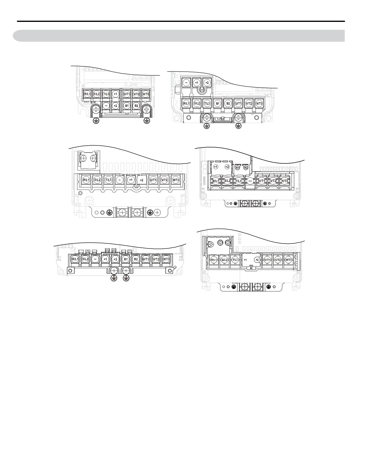
Figure 3.5 provides illustrations of the main circuit terminal block configurations of the different drive sizes.
Models BV0006 to BV0012
Model 2V0006
2V0010 to 2V0020
4V0002 to 4V0011
Models 2V0030 and 2V0040
4V0018 and 4V0023
Model 2V0069
Models 2V0056
4V0031 and 4V0038
Model BV0018
Figure 3.5 Main Circuit Terminal Block Configurations
44
3.4 Protective Covers
3.4
Protective Covers
Follow the procedure below to remove the protective covers before wiring the drive and to reattach the covers after wiring is
complete.
u IP20/NEMA 1, UL Type 1 Front and Bottom Cover Removal and Installation
n Removing the Protective Covers on an IP20/NEMA 1, UL Type 1 Design
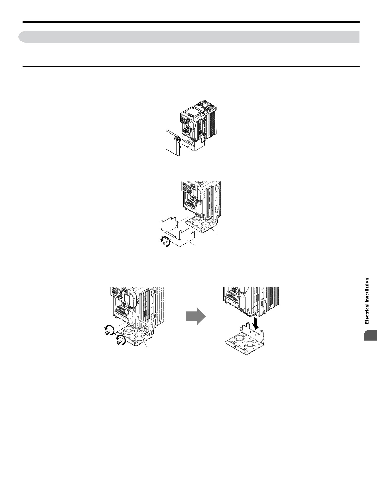
1. Loosen the screw on the front cover to remove the front cover.
Figure 3.6 Remove the Front Cover on an IP20/NEMA 1, UL Type 1 Drive
2. Loosen the screw on the terminal cover to remove the terminal cover and expose the conduit bracket.
A
B
A - Conduit bracket
B - Terminal cover
Figure 3.7 Remove the Terminal Cover on an IP20/NEMA 1, UL Type 1
Drive
3. Loosen two screws attaching the conduit bracket to remove.
3
A
A -Conduit bracket
Figure 3.8 Remove the Conduit Bracket on an IP20/NEMA 1, UL Type 1 Drive
45
3.4 Protective Covers
n Reattaching the Protective Covers
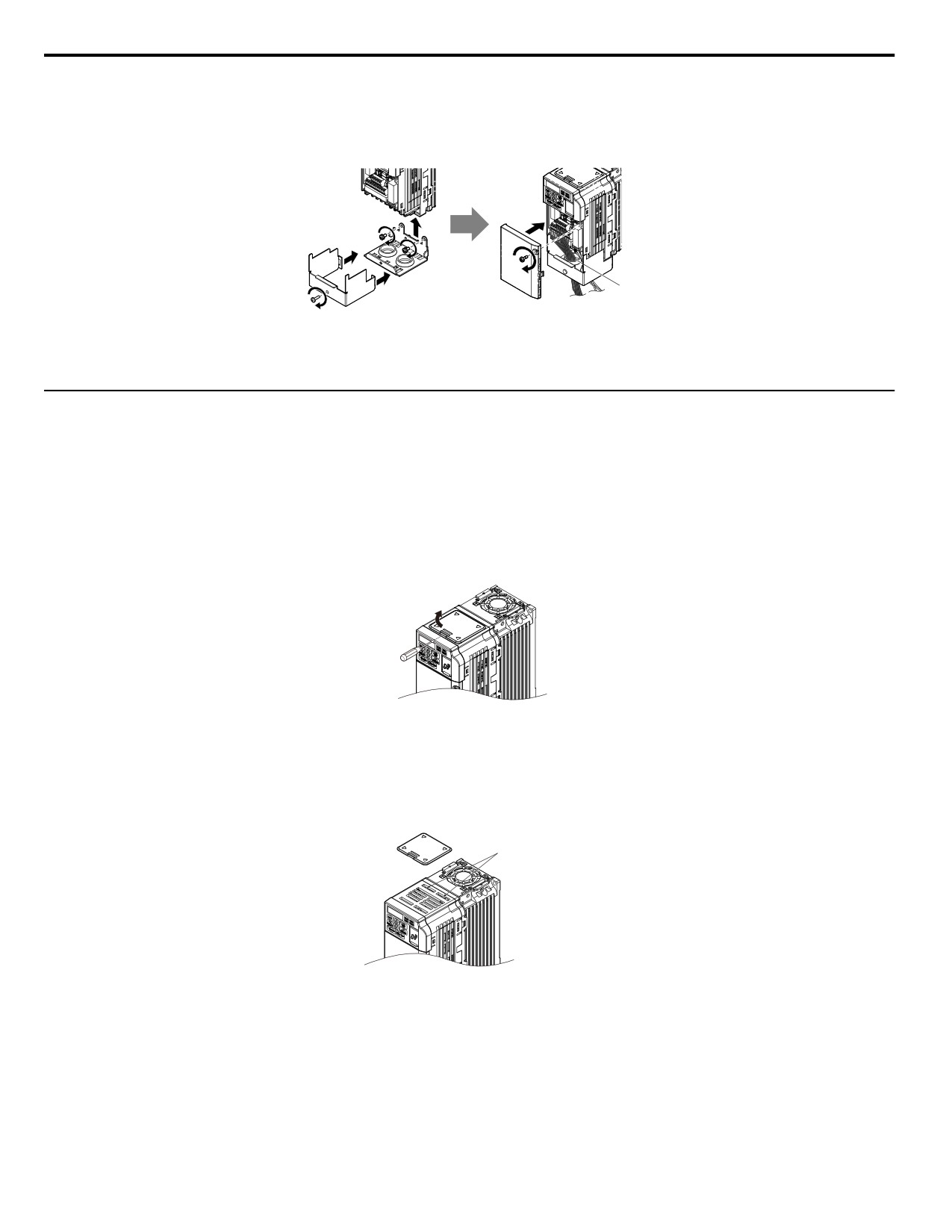
Pass power wiring and control signal wiring through the exit
holes on the bottom of the conduit bracket of the drive. Place
power wiring and control signal wiring in separate conduits. Properly connect all wiring after installing the drive and connecting
other devices. Reattach all protective covers when wiring
is complete.
A
A -Pass power wiring and control signal wiring through different exit holes at the
bottom of the drive.
Figure 3.9 Reattach the Protective Covers and Conduit Bracket on an IP20/NEMA 1, UL Type 1 Drive
u IP20/NEMA 1, UL Type 1 Top Cover Removal and Installation
To improve the ambient temperature rating of a NEMA 1, UL Type 1 drive from 40 °C to 50 °C or to mount NEMA 1, UL
Type 1 drives side-by-side, the top cover can be removed. Remove the top cover and set L8-35 to 2.
Note:
Removing the top cover of a NEMA 1, UL Type 1 drive converts the drive to an IP20/Open-Chassis rating, and the drive will no longer
have a NEMA 1, UL Type 1 rating.
n Removing the Top Cover
Insert the blade of a straight-edge screwdriver into the opening of the top cover. Gently lift up on the front cover as indicated
by the arrow in Figure 3.10 to remove it from the drive.
Figure 3.10 Removing the Top Cover
n Reattaching the Top Cover
Align the connection tabs on the underside of the top cover with the connection tabs on the drive. Pinch in on the top cover
to click the cover into place on the drive.
Connection tabs
Figure
3.11
Reattaching the Top Cover
46
3.5 Preparing IP66/NEMA 4X, UL Type 4X Enclosure Drives for Wiring
3.5
Preparing IP66/NEMA 4X, UL Type 4X Enclosure Drives for
Wiring
u Select Cable Gland
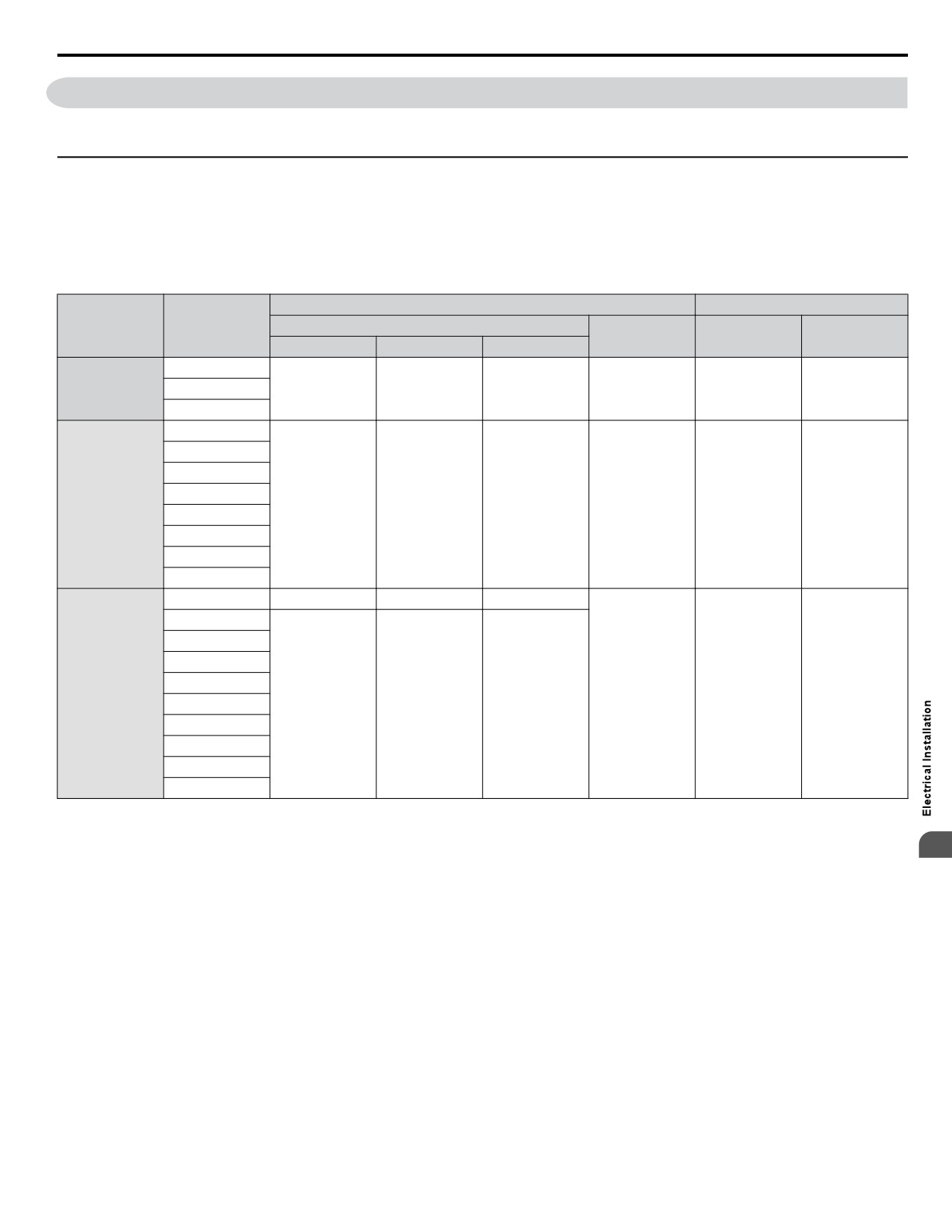
Specific cable glands and gland plate covers are not listed for North America. Table 3.1 lists the enclosure conduit hole
dimensions by drive model. Use this table to select cable glands or gland plate covers from a local supplier. Use UL approved
cable glands or gland cover plates with NEMA 4X, UL Type 4X, or IP66 integrity for all drive conduit holes. Cable glands
or gland plate covers are supplied by the customer.
Table 3.1 Conduit Hole Dimensions
Main Circuit
Control Circuit
Voltage Class
Model
Conduit Hole Diameter mm (in)
Number of
Hole Diameter
Total Holes
Input Holes
Output Holes
Option Holes
Holes
mm (in)
BV0006G
Single-Phase
BV0010G
28 (1.10)
28 (1.10)
28 (1.10)
1
22 (0.87)
3
200 V Class
BV0012G
2V0006G
2V0010G
2V0012G
Three-Phase
2V0020G
28 (1.10)
28 (1.10)
28 (1.10)
1
22 (0.87)
3
200 V Class
2V0030G
2V0040G
2V0056G
2V0069G
4V0002
22 (0.87)
22 (0.87)
22 (0.87)
4V0004
4V0005
4V0007
4V0009
Three-Phase
1
22 (0.87)
3
400 V Class
4V0011
28 (1.10)
28 (1.10)
28 (1.10)
4V0018
4V0023
4V0031
4V0038
n Remove Rubber Bushings and Insert Cable Glands
NOTICE: Do not pinch or damage the sealing gasket when attaching the front cover. Damage to the gasket may allow moisture or dust to
3
enter the protective enclosure and damage drive components.
NOTICE: Do not use silicone sealant with cable glands or front cover to reinforce waterproofing. Corrosive vapors produced by the sealant
can damage circuit boards and compromise the watertight integrity of the protective enclosure.
NOTICE: Use only the recommended multi conductor cable and use only one cable per cable gland. Attempting to pass more than one wire
through a cable gland create a space between wires that reduces the waterproofing and dustproofing capabilities of the cable gland, and
may damage the drive.
NOTICE: Properly seal the rubber gasket along the outside of the cable gland. Improper seals may allow water or oil into the drive and
damage components.
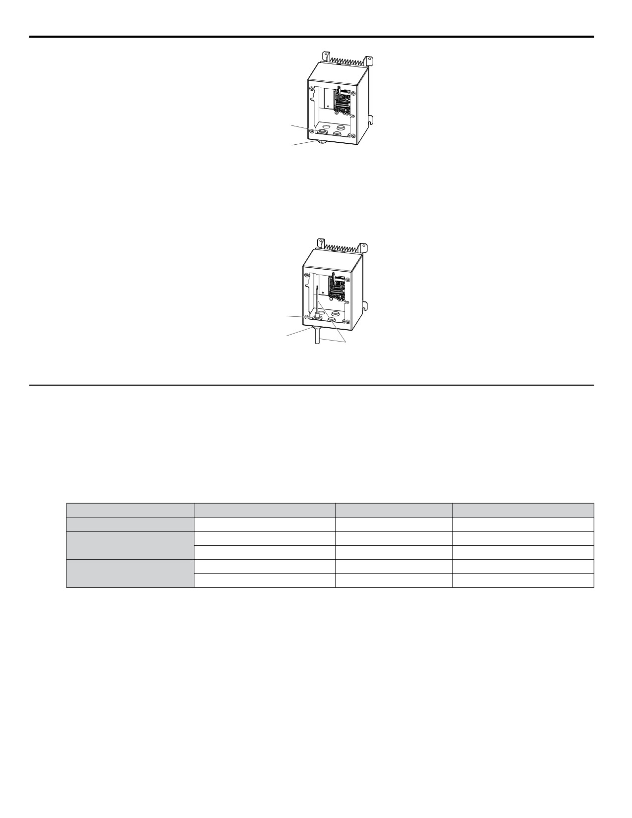
Remove the rubber bushings and insert the proper cable glands into the holes and tighten the glands with the locknut.
47
3.5 Preparing IP66/NEMA 4X, UL Type 4X Enclosure Drives for Wiring
Cable gland
(Locknut)
Cable gland
(Body)
Figure 3.12 Inserting the Cable Glands
n Route Cables Through Cable Glands
Route the cables through the cable glands then tighten the cable gland caps to complete preparation for main circuit and control
circuit wiring.
Cable gland
(Locknut)
Cable gland
(Body)
Cable
Figure 3.13 Cable Routing
u IP66/NEMA 4X, UL Type 4X Enclosure Front Cover Removal and Installation
NOTICE: Do not attempt to disassemble the protective enclosure surrounding the drive. The protective enclosure is constructed as a single
piece to include the heatsink. Attempting to disassemble the enclosure may void the protective integrity of the enclosure.
1. Loosen the 4 bolts that attach the enclosure front cover in place, gently move the front cover away from the enclosure.
Refer to Table 3.2 for installation bolt size.
Press firmly on the digital operator cable connector release tab to disconnect the cable from port CN1 on the drive,
then remove the front cover.
Table 3.2 IP66/NEMA 4X, UL Type 4X Enclosure Front Cover Installation Bolt Size and Torque
Voltage Class
Drive Model
Installation Bolt Size
Tightening Torque N•m (lb-in)
Single-Phase 200 V Class
BV0001G to BV0012G
M5
2.0 to 2.5 (17.7 to 22.1)
2V0001G to 2V0020G
M5
2.0 to 2.5 (17.7 to 22.1)
Three-Phase 200 V Class
2V0030G to 2V0069G
M6
5.4 to 6.0 (47.8 to 53)
4V0001G to 4V0011G
M5
2.0 to 2.5 (17.7 to 22.1)
Three-Phase 400 V Class
4V0018G to 4V0038G
M6
5.4 to 6.0 (47.8 to 53)
48
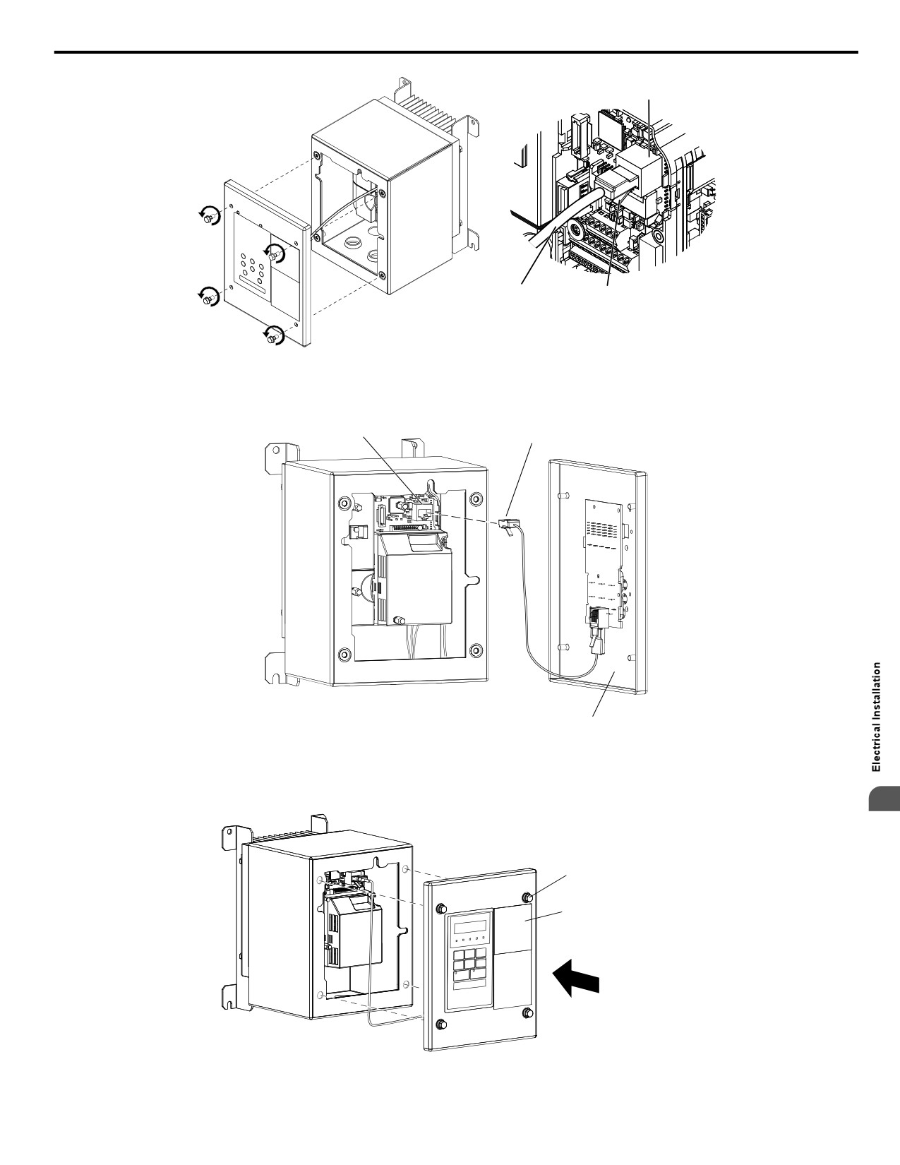
3.5 Preparing IP66/NEMA 4X, UL Type 4X Enclosure Drives for Wiring
Port
CN1
Digital
Connector
Operator
Release Tab
Cable
Figure 3.14 Remove the Enclosure Front Cover
2. Reattach the digital operator cable to the drive.
Insert Digital
CN1 Port
Operator Cable
Drive
Inside Front Cover
Figure 3.15 Insert Digital Operator Cable
3. Reattach the front cover of the drive enclosure. Refer to Table 3.2 for tightening torque specifications.
3
Drive
Front Cover Screw (4)
Front Cover
Figure 3.16 Attach Enclosure Cover
49
3.6 Main Circuit Wiring
3.6
Main Circuit Wiring
This section describes the functions, specifications, and procedures required to safely and properly wire the main circuit of
the drive.
NOTICE: Do not solder the ends of wire connections to the drive. Soldered wiring connections can loosen over time. Improper wiring practices
could result in drive malfunction due to loose terminal connections.
u Main Circuit Terminal Functions
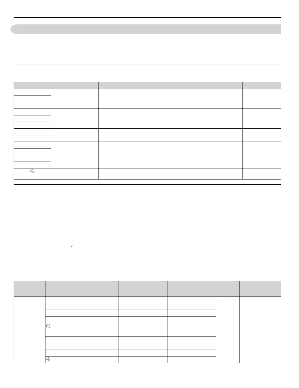
Table 3.3 Main Circuit Terminal Functions
Terminal
Type
Function
Reference
R/L1
Connects line power to the drive.
Main circuit power supply
S/L2
Drives with single-phase 200 V input power use terminals R/L1 and S/L2 only.
-
input
Do NOT use T/L3.
T/L3
U/T1
V/T2
Drive output
Connects to the motor.
53
W/T3
B1
Braking resistor
Available for connecting a braking resistor or the braking resistor unit option.
-
B2
Պ1
These terminals are shorted at shipment. Remove the shorting bar between Պ1
DC link choke connection
-
Պ2
and Պ2 when connecting a DC link choke to this terminal.
Պ1
DC power supply input
For connecting a DC power supply.
-
Ջ
Ground
Grounding Terminal
53
(2 terminals)
u Wire Gauges and Tightening Torques
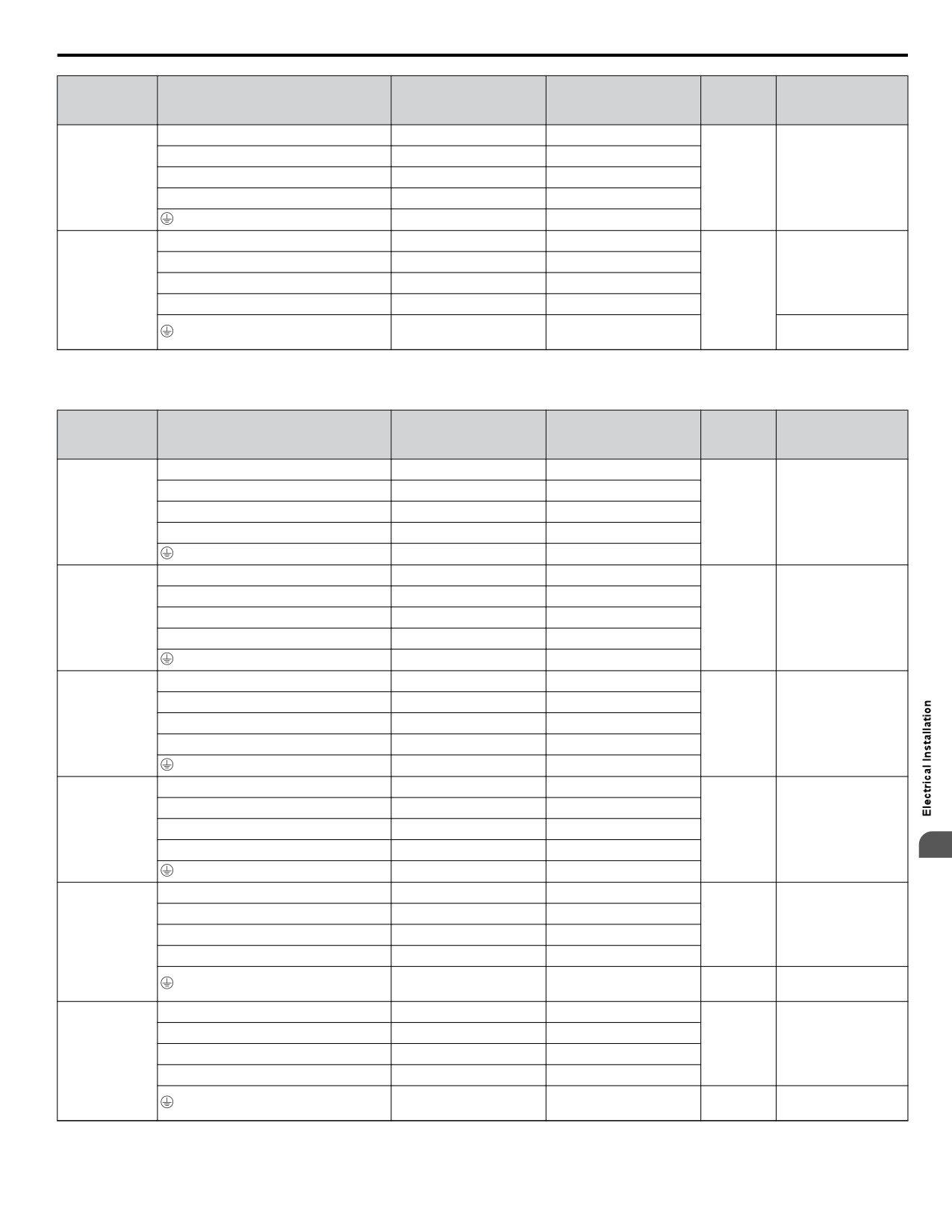
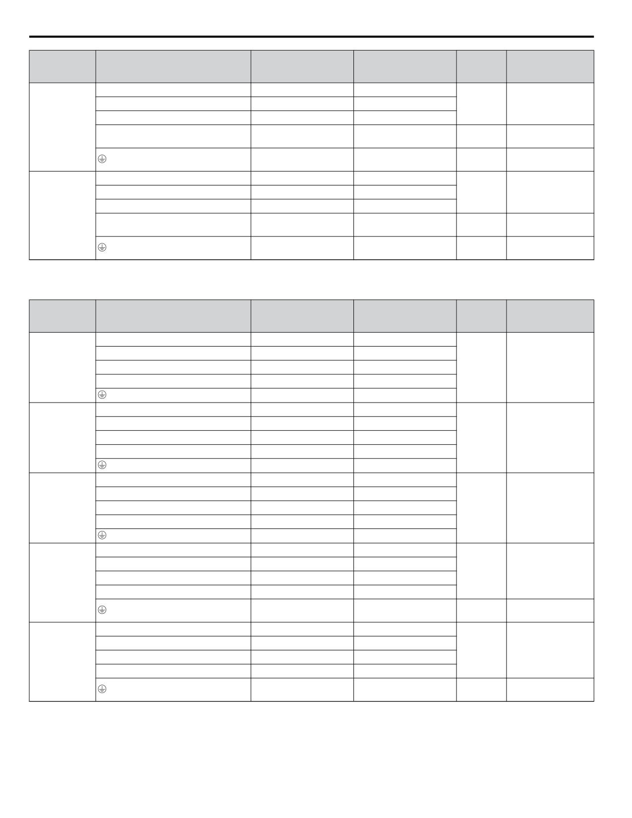
Select the appropriate wires and crimp terminals from Table 3.4 through Table 3.6.
Note:
1. Wire gauge recommendations based on drive continuous current ratings using 75 °C 600 Vac vinyl-sheathed wire assuming ambient
temperature within 30 °C and wiring distance shorter than 100 m.
2. Terminals Պ1, Պ2, Ջ, B1 and B2 are for connecting optional devices such as a braking resistor. Do not connect other non-specified
devices to these terminals.
• Consider the amount of voltage drop when selecting wire gauges. Increase the wire gauge when the voltage drop is greater
than 2% of motor rated voltage. Ensure the wire gauge is suitable for the terminal block. Use the following formula to
calculate the amount of voltage drop:
• Line drop voltage (V) =
3 x wire resistance (Ω/km) x wire length (m) x current (A) x 10-3
• Refer to instruction manual TOBP C720600 00 for braking unit or braking resistor unit wire gauges.
• Refer to UL Standards Compliance on page 427 for information on UL compliance.
n Single-Phase 200 V Class
Table 3.4 Wire Gauge and Torque Specifications
Recomm.
Tightening
Drive
Wire Range
Screw
Terminal
Gauge
Torque
Model
AWG, kcmil
Size
AWG, kcmil
N•m (lb.in.)
R/L1, S/L2, T/L3
12
14 to 10
U/T1, V/T2, W/T3
14
14 to 10
1.2 to 1.5
BV0006
Ջ, Պ1, Պ2
-
14 to 10
M4
(10.6 to 13.3)
B1, B2
-
14 to 10
10
14 to 10
R/L1, S/L2, T/L3
10
14 to 10
U/T1, V/T2, W/T3
14
14 to 10
1.2 to 1.5
BV0010
Ջ, Պ1, Պ2
-
14 to 10
M4
(10.6 to 13.3)
B1, B2
-
14 to 10
10
14 to 10
50
3.6 Main Circuit Wiring
Recomm.
Tightening
Drive
Wire Range
Screw
Terminal
Gauge
Torque
Model
AWG, kcmil
Size
AWG, kcmil
N•m (lb.in.)
R/L1, S/L2, T/L3
10
14 to 10
U/T1, V/T2, W/T3
14
14 to 10
2.3 to 2.5
BV0012
Ջ, Պ1, Պ2
-
14 to 10
M4
(20.4 to 22.1)
B1, B2
-
14 to 10
10
14 to 10
R/L1, S/L2, T/L3
8
12 to 8
U/T1, V/T2, W/T3
10
12 to 8
2.3 to 2.5
Ջ, Պ1, Պ2
-
12 to 8
(20.4 to 22.1)
BV0018
M5
B1, B2
-
12 to 8
2 to 2.5
8
12 to 8
(17.7 to 22.1)
n
Three-Phase 200 V Class
Table 3.5
Wire Gauge and Torque Specifications
Recomm.
Tightening
Drive
Wire Range
Screw
Terminal
Gauge
Torque
Model
AWG, kcmil
Size
AWG, kcmil
N•m (lb.in.)
R/L1, S/L2, T/L3
14
18 to 14
U/T1, V/T2, W/T3
14
18 to 14
0.8 to 1.0
2V0006
Ջ, Պ1, Պ2
-
18 to 14
M3.5
(7.1 to 8.9)
B1, B2
-
18 to 14
14
18 to 14
R/L1, S/L2, T/L3
12
14 to 10
U/T1, V/T2, W/T3
14
14 to 10
1.2 to 1.5
2V0010
Ջ, Պ1, Պ2
-
14 to 10
M4
(10.6 to 13.3)
B1, B2
-
14 to 10
10
14 to 10
R/L1, S/L2, T/L3
12
14 to 10
U/T1, V/T2, W/T3
14
14 to 10
1.2 to 1.5
2V0012
Ջ, Պ1, Պ2
-
14 to 10
M4
(10.6 to 13.3)
B1, B2
-
14 to 10
10
14 to 10
R/L1, S/L2, T/L3
10
14 to 10
U/T1, V/T2, W/T3
10
14 to 10
1.2 to 1.5
2V0020
Ջ, Պ1, Պ2
-
14 to 10
M4
(10.6 to 13.3)
B1, B2
-
14 to 10
3
10
14 to 10
R/L1, S/L2, T/L3
8
10 to 6
U/T1, V/T2, W/T3
8
10 to 6
2.1 to 2.3
M4
Ջ, Պ1, Պ2
-
10 to 6
(18.6 to 20.4)
2V0030
B1, B2
-
14 to 10
2 to 2.5
8
10 to 6
M5
(17.7 to 22.1)
R/L1, S/L2, T/L3
6
10 to 6
U/T1, V/T2, W/T3
8
10 to 6
2.1 to 2.3
M4
(18.6 to 20.4)
Ջ, Պ1, Պ2
-
10 to 6
2V0040
B1, B2
-
14 to 10
2 to 2.5
6
10 to 6
M5
(17.7 to 22.1)
51
3.6
Main Circuit Wiring
Recomm.
Tightening
Drive
Wire Range
Screw
Terminal
Gauge
Torque
Model
AWG, kcmil
Size
AWG, kcmil
N•m (lb.in.)
R/L1, S/L2, T/L3
4
6 to 4
5.4 to 6.0
U/T1, V/T2, W/T3
4
6 to 4
M6
(47.8 to 53.1)
Ջ, Պ1, Պ2
-
6 to 4
2V0056
2.7 to 3.0
B1, B2
-
10 to 6
M5
(23.9 to 26.6)
5.4 to 6.0
6
8 to 4
M6
(47.8 to 53.1)
R/L1, S/L2, T/L3
3
8 to 2
9.9 to 11
U/T1, V/T2, W/T3
3
8 to 2
M8
(87.6 to 97.4)
Ջ, Պ1, Պ2
-
8 to 2
2V0069
2.7 to 3.0
B1, B2
-
8 to 6
M5
(23.9 to 26.6)
5.4 to 6.0
6
6 to 4
M6
(47.8 to 53.1)
n
Three-Phase 400 V Class
Table 3.6
Wire Gauge and Torque Specifications
Recomm.
Tightening
Drive
Wire Range
Screw
Terminal
Gauge
Torque
Model
AWG, kcmil
Size
AWG, kcmil
N•m (lb.in.)
R/L1, S/L2, T/L3
14
14 to 10
U/T1, V/T2, W/T3
14
14 to 10
4V0002
1.2 to 1.5
Ջ, Պ1, Պ2
-
14 to 10
M4
4V0004
(10.6 to 13.3)
B1, B2
-
14 to 10
14
14 to 10
R/L1, S/L2, T/L3
14
14 to 10
U/T1, V/T2, W/T3
14
14 to 10
4V0005
1.2 to 1.5
4V0007
Ջ, Պ1, Պ2
-
14 to 10
M4
(10.6 to 13.3)
4V0009
B1, B2
-
14 to 10
10
14 to 10
R/L1, S/L2, T/L3
12
14 to 10
U/T1, V/T2, W/T3
14
14 to 10
1.2 to 1.5
4V0011
Ջ, Պ1, Պ2
-
14 to 10
M4
(10.6 to 13.3)
B1, B2
-
14 to 10
10
14 to 10
R/L1, S/L2, T/L3
10
14 to 6
U/T1, V/T2, W/T3
10
14 to 6
2.1 to 2.3
M4
Ջ, Պ1, Պ2
-
14 to 6
(18.6 to 20.4)
4V0018
B1, B2
-
14 to 10
2 to 2.5
8
14 to 6
M5
(17.7 to 22.1)
R/L1, S/L2, T/L3
10
10 to 6
U/T1, V/T2, W/T3
10
10 to 6
2.1 to 2.3
M4
Ջ, Պ1, Պ2
-
10 to 6
(18.6 to 20.4)
4V0023
B1, B2
-
14 to 10
2 to 2.5
8
10 to 6
M5
(17.7 to 22.1)
52
3.6 Main Circuit Wiring
Recomm.
Tightening
Drive
Wire Range
Screw
Terminal
Gauge
Torque
Model
AWG, kcmil
Size
AWG, kcmil
N•m (lb.in.)
R/L1, S/L2, T/L3
8
10 to 6
3.6 to 4.0
U/T1, V/T2, W/T3
8
10 to 6
(31.8 to 35.4)
Ջ, Պ1, Պ2
-
10 to 6
M5
4V0031
2.7 to 3.0
B1, B2
-
14 to 10
(23.9 to 26.6)
5.4 to 6.0
6
10 to 6
M6
(47.8 to 53.1)
R/L1, S/L2, T/L3
6
10 to 6
3.6 to 4.0
U/T1, V/T2, W/T3
8
10 to 6
(31.8 to 35.4)
Ջ, Պ1, Պ2
-
10 to 6
M5
4V0038
2.7 to 3.0
B1, B2
-
10 to 8
(23.9 to 26.6)
5.4 to 6.0
6
10 to 6
M6
(47.8 to 53.1)
u Main Circuit Terminal Power Supply and Motor Wiring
This section outlines the various steps, precautions, and checkpoints for wiring the main circuit terminals and motor terminals.
NOTICE: When connecting the motor to the drive output terminals U/T1, V/T2, and W/T3, the phase order for the drive and motor should
match. Failure to comply with proper wiring practices may cause the motor to run in reverse if the phase order is backward.
NOTICE: Route motor leads U/T1, V/T2, and W/T3 separate from all other leads to reduce possible interference related issues. Failure to
comply may result in abnormal operation of drive and nearby equipment.
NOTICE: Do not connect phase-advancing capacitors or LC/RC noise filters to the output circuits. Improper application of noise filters could
result in damage to the drive.
NOTICE: Do not connect the AC power line to the output motor terminals of the drive. Failure to comply could result in death or serious
injury by fire as a result of drive damage from line voltage application to output terminals.
n Cable Length Between Drive and Motor
When the cable length between the drive and the motor is too long (especially at low frequency output), note that the cable
voltage drop may cause reduced motor torque. Drive output current will increase as the leakage current from the cable increases.
An increase in leakage current may trigger an overcurrent situation and weaken the accuracy of the current detection.
Adjust the drive carrier frequency according to the following table. If the motor wiring distance exceeds 100 m because of the
system configuration, reduce the ground currents.
Refer to Table 3.7 to set the carrier frequency to an appropriate level.
Table 3.7 Cable Length Between Drive and Motor
Cable Length
50 m or shorter
100 m or shorter
Longer than 100 m
Carrier Frequency
15 kHz or less
5 kHz or less
2 kHz or less
3
Note:
When setting carrier frequency, calculate the cable length as the total distance of wiring to all connected motors when running multiple
motors from a single drive.
n Ground Wiring
Follow the precautions to wire the ground for one drive or a series of drives.
WARNING! Electrical Shock Hazard. Always use a ground wire that complies with technical standards on electrical equipment and minimize
the length of the ground wire. Improper equipment grounding may cause dangerous electrical potentials on equipment chassis, which could
result in death or serious injury.
WARNING! Electrical Shock Hazard. Be sure to ground the drive ground terminal. (200 V Class: Ground to 100 Ω or less, 400 V Class:
Ground to 10 Ω or less). Improper equipment grounding could result in death or serious injury by contacting ungrounded electrical equipment.
NOTICE: Do not share the ground wire with other devices such as welding machines or large-current electrical equipment. Improper
equipment grounding could result in drive or equipment malfunction due to electrical interference.
NOTICE: When using more than one drive, ground multiple drives according to instructions. Improper equipment grounding could result in
abnormal operation of drive or equipment.
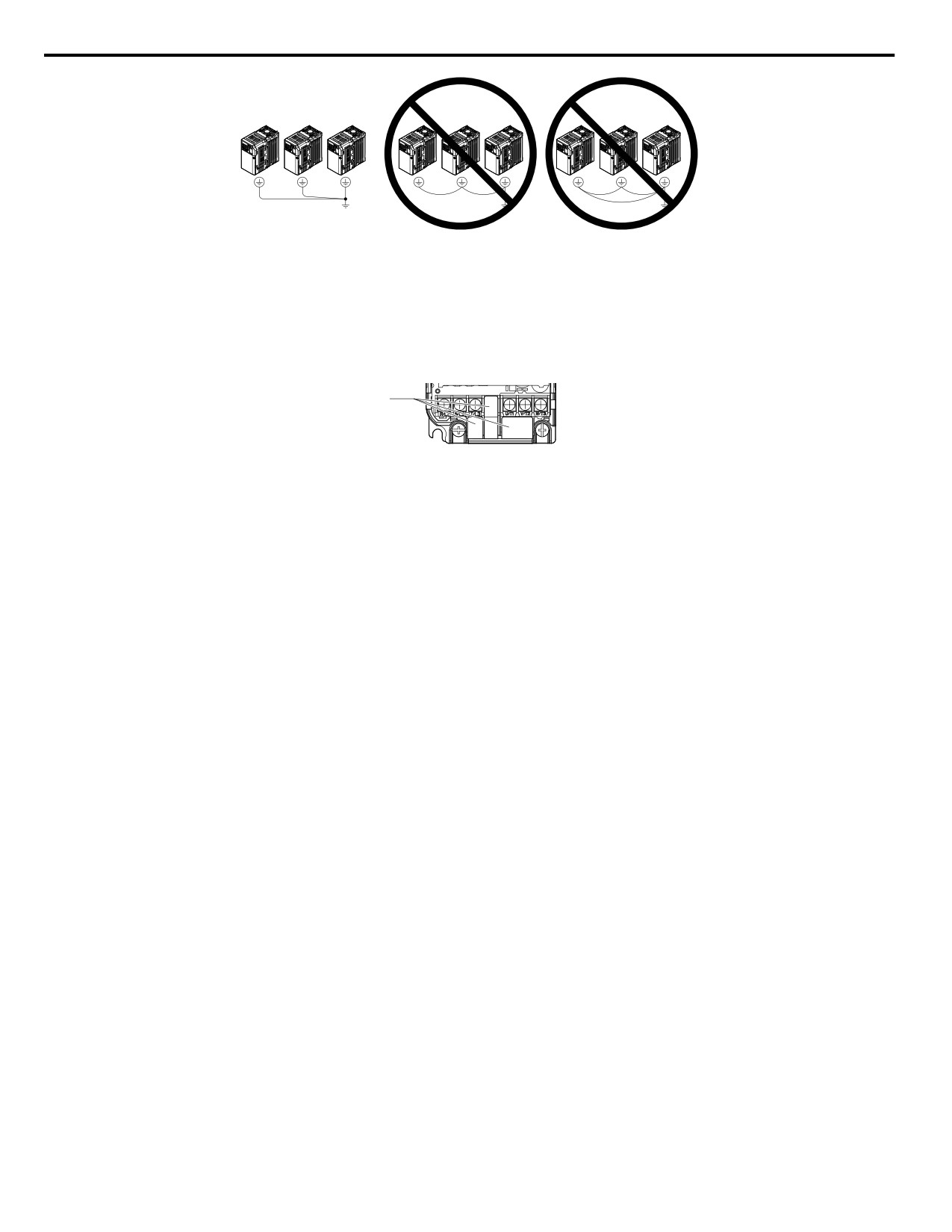
Refer to Figure 3.17 when using multiple drives. Do not loop the ground wire.
53
3.6 Main Circuit Wiring
Figure 3.17
Multiple Drive
Wiring
n Wiring the Main Circuit Terminal
WARNING! Electrical Shock Hazard. Shut off the power supply
to the drive before
wiring the main circuit terminals. Failure to comply may
result in death or serious injury.
Note:
A cover placed over the DC Bus and braking circuit terminals prior to shipment helps prevent miswiring. Cut away covers as needed for
terminals with a needle-nose pliers.
A
A -Protective Cover to Prevent Miswiring
Note:
The ground terminal screw on IP20/NEMA 1, UL Type 1 holds the protective cover in place on model 2V0006.
54
3.7 Control Circuit Wiring
3.7
Control Circuit Wiring
u Control Circuit Terminal Block Functions
Drive parameters determine which functions apply to the multi-function digital inputs (S1 to S7), multi-function digital outputs
(MA, MB), multi-function pulse inputs and outputs (RP, MP) and multi-function photocoupler outputs (P1, P2). The default
is called out next to each terminal in Figure 3.1.
WARNING! Sudden Movement Hazard. Always check the operation and wiring of control circuits after being wired. Operating a drive with
untested control circuits could result in death or serious injury.
WARNING! Confirm the drive I/O signals and external sequence before starting test run. Setting parameter A1-06 may change the I/O
terminal function automatically from the factory setting. Failure to comply may result in death or serious injury.
n Input Terminals
Table 3.8 Control Circuit Input Terminals
Type
No.
Terminal Name (Function)
Function (Signal Level) Default Setting
Multi-function input 1 (Closed: Forward run, Open:
S1
Stop)
S2
Multi-function input 2 (Not used/Through mode)
Photocoupler
S3
Multi-function input 3 (External pump fault (N.O.)
24 Vdc, 8 mA
Note: Drive preset to sinking mode. When using source mode, set
Multi-Function
S4
Multi-function input 4 (Fault reset)
DIP switch S3 to allow for a 24 Vdc (±10%) external power supply.
Digital Inputs
S5
Multi-function input 5 (Multi-step speed reference 1)
Refer to Sinking/Sourcing Mode Switch on page 59 for details.
S6
Multi-function input 6 (HAND Mode)
S7
Multi-function input 7 (HAND Mode 2)
SC
Multi-function input common (Control common)
Sequence common
HC
Power supply for safe disable input
+24 Vdc (max 10 mA allowed)
Safe Disable
Open: Output disabled
Input
Closed: Normal operation
H1
Safe disable input
Note: Disconnect wire jumper between HC and H1 when using the
safe disable input. The wire length should not exceed 30 m.
Response frequency: 0.5 to 32 kHz
(Duty Cycle: 30 to 70%)
RP
Multi-function pulse train input (frequency reference)
(High level voltage: 3.5 to 13.2 Vdc)
(Low level voltage: 0.0 to 0.8 Vdc)
(input impedance: 3 kΩ)
Main
+V
Analog input power supply
+10.5 Vdc (max allowable current 20 mA)
Frequency
A1
Multi-function analog input 1 (frequency reference)
Input voltage 0 to +10 Vdc (20 kΩ) resolution 1/1000
Reference
Input
Input voltage or input current (Selected by DIP switch S1 and H3-09)
0 to +10 Vdc (20 kΩ),
A2
Multi-function analog input 2 (frequency reference)
Resolution: 1/1000
4 to 20 mA (250 Ω) or 0 to 20 mA (250 Ω),
Resolution: 1/500
AC
Frequency reference common
0 Vdc
3
n Output Terminals
Table 3.9 Control Circuit Output Terminals
Type
No.
Terminal Name (Function)
Function (Signal Level) Default Setting
MA
N.O. (Fault)
Digital output
Multi-Function Digital
MB
N.C. (Fault)
30 Vdc, 10 mA to 1 A; 250 Vac, 10 mA to 1 A
Output <1>
Minimum load: 5 Vdc, 10 mA (reference value)
MC
Digital output common
P1
Photocoupler output 1 (During run)
Multi-Function
P2
Photocoupler output 2 (Fault)
Photocoupler output 48 Vdc, 2 to 50 mA <2>
Photocoupler Output
PC
Photocoupler output common
MP
Pulse train output (Output frequency)
32 kHz (max) <3>
<4>
Monitor Output
AM
Analog monitor output
0 to 10 Vdc (2 mA or less) Resolution: 1/1000
AC
Monitor common
0 V
<1> Do not assign functions to digital relay outputs that involve frequent switching. This may shorten relay performance life. Switching life is estimated
at 200,000 times (assumes 1 A, resistive load).
55
3.7 Control Circuit Wiring
<2> Connect a suppression diode as shown in Figure 3.18 when driving a reactive load such as a relay coil. Ensure the diode rating is greater than the
circuit voltage.
<3> When set for sourcing. +5 V/1.5 kΩ or higher, +8 V/3.5 kΩ or higher, +10 V/10 kΩ or higher.
<4> When set for sinking, the external power supply should be +12 Vdc, ±5% with 16 mA or less.
B
C
A
D
A - External power, 48 V max.
C - Coil
B - Suppression diode
D - 50 mA or less
Figure 3.18 Connecting a Suppression Diode
n Serial Communication Terminals
Table 3.10 Control Circuit Terminals: Serial Communications
Type
No.
Signal Name
Function (Signal Level)
R+
Communications input (+)
RS-485/422
MEMOBUS/
R-
Communications input (-)
MEMOBUS/Modbus communication: Use a
Modbus
MEMOBUS/Modbus
S+
Communications output (+)
RS-485 or RS-422 cable to connect the drive.
communication
Communication
protocol 115.2 kbps
S-
Communications output (-)
(max.)
IG
Shield ground
0 V
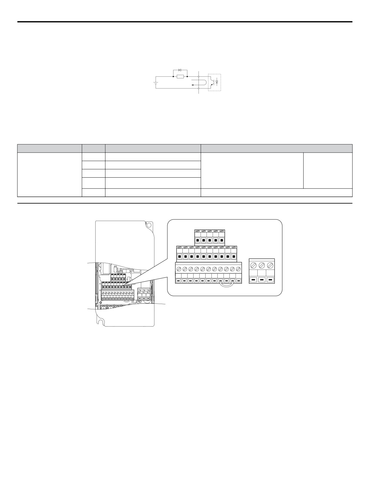
u Terminal Configuration
R+ R- S+ S- IG
P1
P2
PC A1
A2
+V AC AM AC MP
MA
MB
MC
R+ R- S+ S- IG
S1
S2
S3
S4
S5
S6
S7
HC SC H1
RP
P1
P2
PC A1
A2
+V AC AM AC MP
S1
S2
S3
S4
S5
S6
S7
HC SC H1
RP
MA MB MC
Figure 3.19 Removable Control Circuit Terminal Block
56
3.7 Control Circuit Wiring
n Wire Size and Torque Specifications
Select appropriate wire type and size from Table 3.11. For simpler and more reliable wiring, crimp ferrules to the wire ends.
Refer to Table 3.12 for ferrule terminal types and sizes.
Table 3.11 Wire Size and Torque Specifications (Same for All Models)
Tightening
Bare Wire Terminal
Ferrule-Type Terminal
Screw
Torque
Applic. wire size
Terminal
Size
N•m
Applic. wire size
Recomm. mm2
Recomm. mm2
mm2
Wire Type
(in-lbs)
mm2 (AWG)
(AWG)
(AWG)
(AWG)
Stranded: 0.25 to 1.5
0.5 to 0.6
(24 to 16)
0.25 to 1.0
MA, MB, MC
M3
0.75 (18)
0.5 (20)
(4.4 to 5.3)
Single: 0.25 to 1.5
(24 to 17)
(24 to 16)
S1-S7, SC, RP,
Shielded line,
+V, A1, A2, AC,
Stranded: 0.25 to 1.0
etc.
HC, H1, P1, P2,
0.22 to 0.25
(24 to 18)
0.25 to 0.5
M2
0.75 (18)
0.5 (20)
PC, MP, AM,
(1.9 to 2.2)
Single: 0.25 to 1.5
(24 to 20)
AC, S+, S-, R+,
(24 to 16)
R-, IG
n Ferrule-Type Wire Terminations
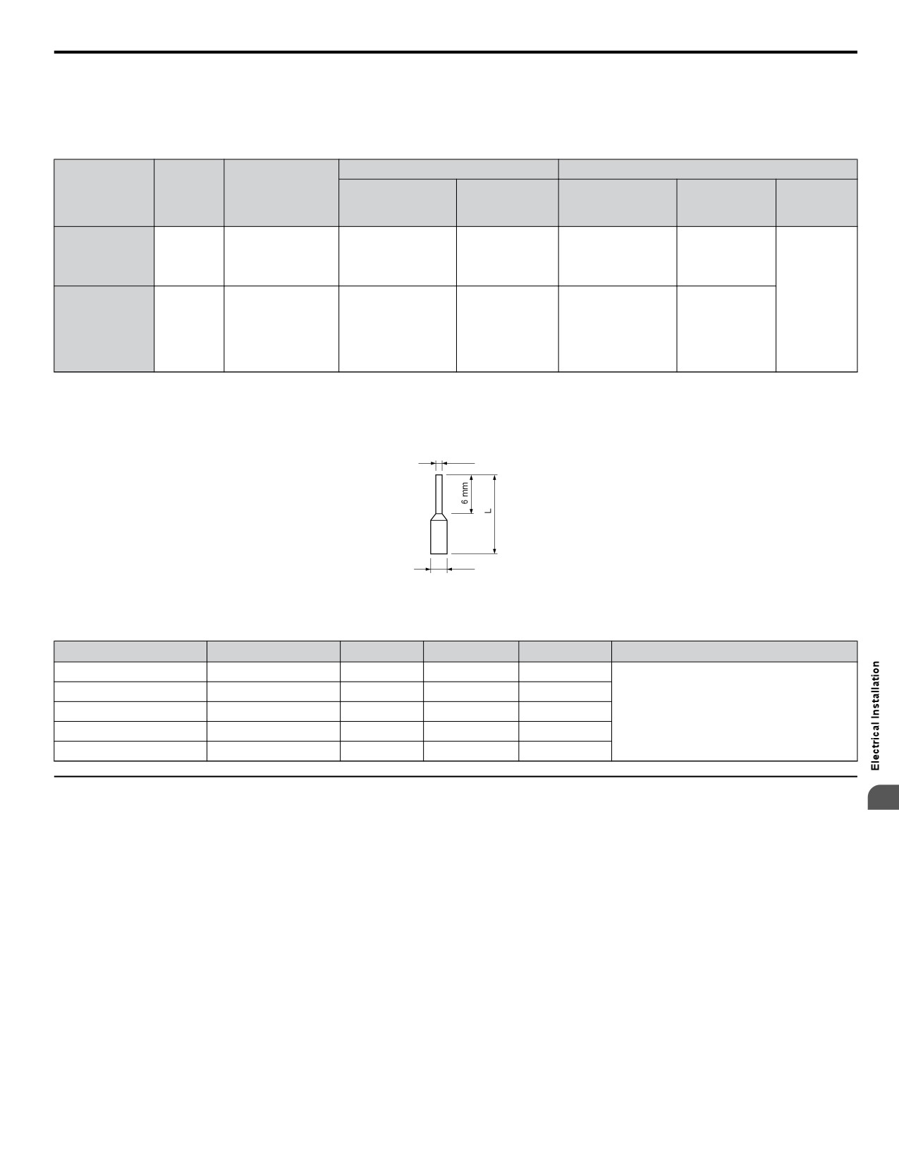
Crimp a ferrule to signal wiring to improve wiring simplicity and reliability. Use CRIMPFOX 6, a crimping tool manufactured
by PHOENIX CONTACT.
d1
d2
Figure 3.20 Ferrule Dimensions
Table 3.12 Ferrule Terminal Types and Sizes
Size mm2 (AWG)
Type
L (mm)
d1 (mm)
d2 (mm)
Manufacturer
0.25 (24)
AI 0.25-6YE
10.5
0.8
2.0
0.34 (22)
AI 0.34-6TQ
10.5
0.8
2.0
0.5 (20)
AI 0.5-6WH
12
1.1
2.5
PHOENIX CONTACT
0.75 (18)
AI 0.75-6GY
12
1.3
2.8
1.0
AI 1-6RD
12
1.5
3.0
u Wiring the Control Circuit Terminal
3
This section describes the proper procedures and preparations for wiring the control terminals.
WARNING! Electrical Shock Hazard. Do not remove covers or touch the circuit boards while the power is on. Failure to comply could result
in death or serious injury.
NOTICE: Separate control circuit wiring from main circuit wiring (terminals R/L1, S/L2, T/L3, B1, B2, U/T1, V/T2, W/T3, Ջ, Պ1, Պ2) and
other high-power lines. Improper wiring practices could result in drive malfunction due to electrical interference.
NOTICE: Separate wiring for digital output terminals MA, MB and MC from wiring to other control circuit lines. Improper wiring practices
could result in drive or equipment malfunction or nuisance trips.
NOTICE: Use a class 2 power supply (UL standard) when connecting to the control terminals. Improper application of peripheral devices
could result in drive performance degradation due to improper power supply.
NOTICE: Insulate shields with tape or shrink tubing to prevent contact with other signal lines and equipment. Improper wiring practices could
result in drive or equipment malfunction due to short circuit.
NOTICE: Connect the shield of shielded cable to the appropriate ground terminal. Improper equipment grounding could result in drive or
equipment malfunction or nuisance trips.
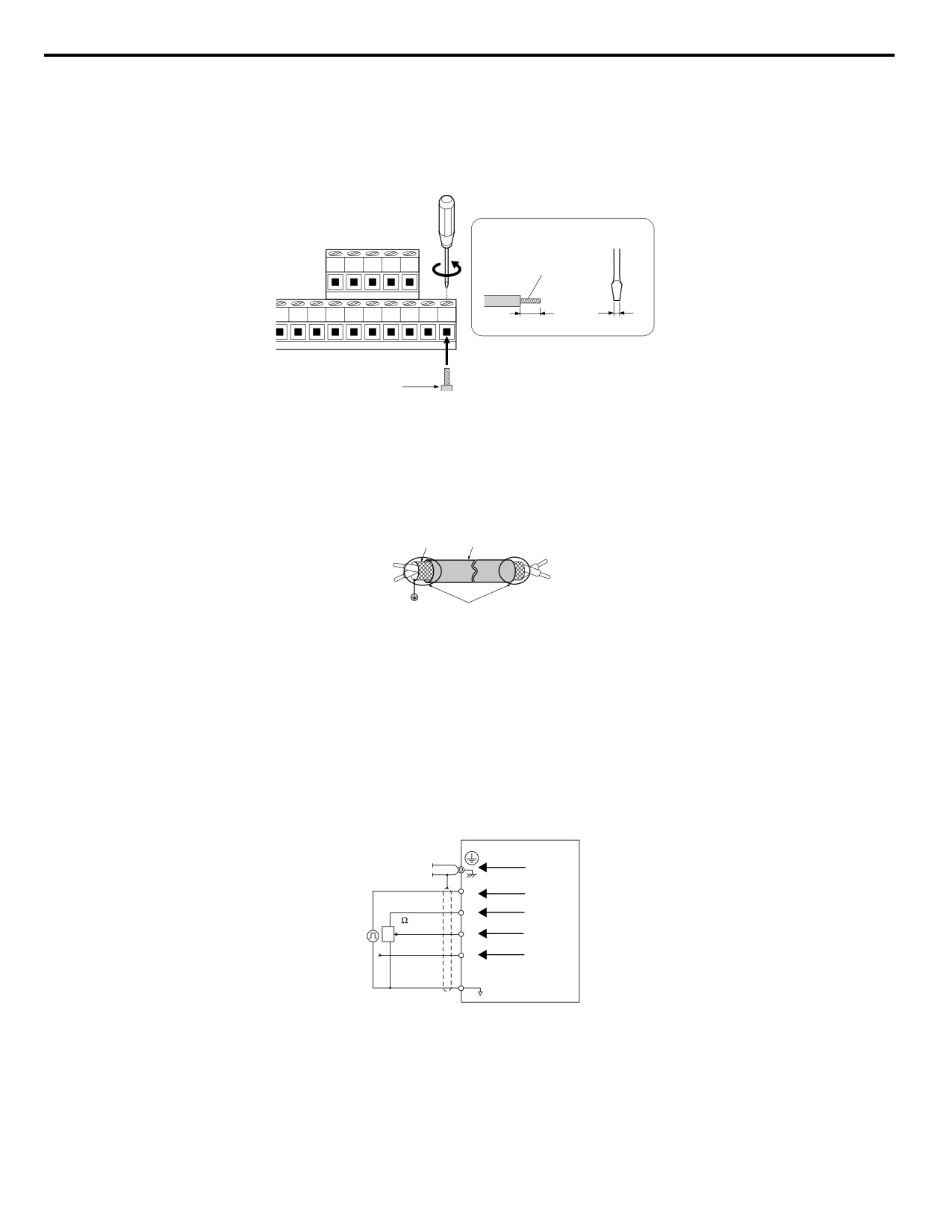
Wire the control terminals using Figure 3.21 as a guide. Prepare the ends of the control circuit wiring as shown in Figure
3.22. Refer to Wire Size and Torque Specifications on page 57 for details.
57
3.7 Control Circuit Wiring
NOTICE: Do not tighten screws beyond the specified tightening torque. Failure to comply may damage the terminal block.
NOTICE: Use shielded twisted-pair cables as indicated to prevent operating faults. Improper wiring practices could result in drive or
equipment malfunction due to electrical interference.
Connect control wires as shown in the following figure:
D
Preparing wire
E
A
terminal ends
B
C
A - Control terminal block
D - Loosen screw to insert wire.
B - Avoid fraying wire strands when
E - Blade depth of 0.4 mm or less
stripping insulation from wire. Strip
Blade width of 2.5 mm or less
length 5.5 mm.
C - Single wire or stranded wire
Figure 3.21 Terminal Board Wiring Guide
F
C
A
D
B
E
A - Drive side
D - Control device side
B - Connect shield to ground terminal
E - Shield sheath (Insulate with tape)
of drive.
F - Shield
C - Insulation
Figure 3.22 Preparing the Ends of Shielded Cables
When setting the frequency by analog reference from an external potentiometer, use shielded twisted-pair wires and ground
the shield of twisted-pair wires to the ground terminal of the drive.
NOTICE: The analog signal lines between the drive and the operator station or peripheral equipment should not exceed 50 meters when
using an analog signal from a remote source to supply the frequency reference. Failure to comply could result in poor system performance.
A
B
RP
C
+V
D
2 k
G
A1
E
A2
F
AC
A - Drive
E - (A1) Main speed frequency
B - Ground terminal (shield
reference 0 to +10 Vdc (20 kΩ)
connection)
F - (A2) Multi-function analog input
C - (RP) Pulse train (maximum 32 kHz)
0 to +10 Vdc (20 kΩ) or
D - (+V) Frequency setting power
4 to 20 mA (250 Ω)/
source +10.5 Vdc maximum 20 mA
0 to 20 mA (250 Ω)
G-Frequency setting potentiometer
Figure 3.23 Wiring the Frequency Reference to the Control Circuit Terminals (External Reference)
58
3.8 I/O Connections
3.8
I/O Connections
u Sinking/Sourcing Mode Switch
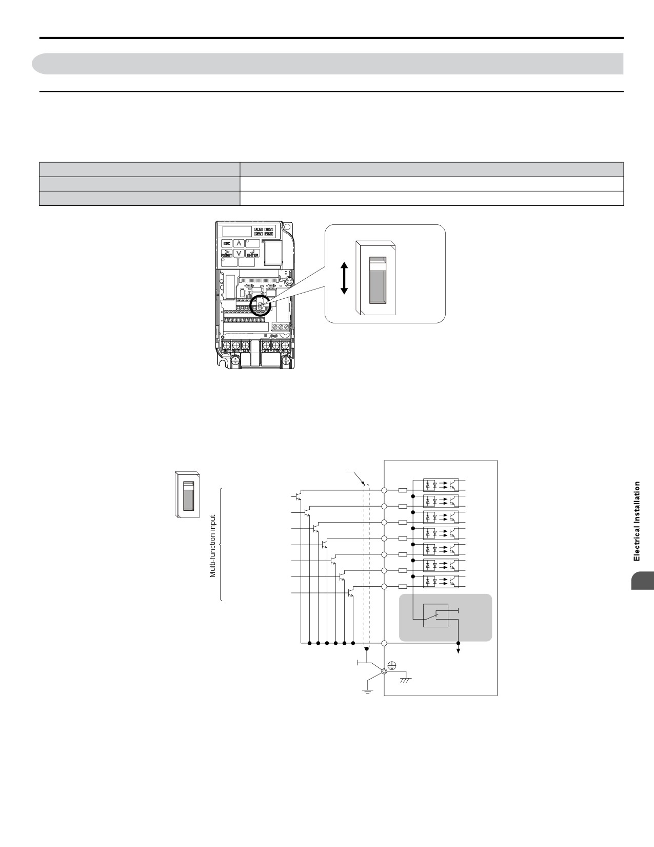
Set the DIP switch S3 on the front of the drive to switch the digital input terminal logic between sinking mode and sourcing
mode; the drive is preset to sinking mode.
Table 3.13 Sinking/Sourcing Mode Setting
Set Value
Details
SINK
Sinking Mode (0 V common): default setting
SOURCE
Sourcing Mode (+24 V common)
DIP Switch S3
SINK
SOURCE
Figure 3.24 DIP Switch S3
n Transistor Input Signal Using 0 V Common/Sink Mode
When controlling the digital inputs by NPN transistors (0 V common/sinking mode), set the DIP switch S3 to SINK and use
the internal 24 V power supply.
SINK
Shielded cable
Drive
S1
Forward run/stop
S2
Not used
S3
SOURCE
External fault N.O.
S4
Fault reset
S5
Multi-setpoint 1
S6
HAND
S7
3
HAND 2
SINK
+24V
S3
SOURCE
SC
Figure 3.25 Sinking Mode: Sequence from NPN Transistor (0 V Common)
59
3.8 I/O Connections
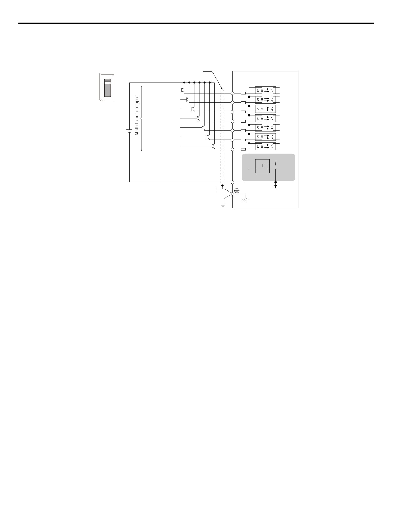
n Transistor Input Signal Using +24 V Common/Source Mode
When controlling digital inputs by PNP transistors (+24 V common/sourcing mode), set the DIP switch S3 to SOURCE and
use an external 24 V power supply.
SINK
Shielded cable
Drive
Forward run / stop
S1
Not used
S2
SOURCE
External fault N.O.
S3
Fault rest
S4
External
Multi-setpoint 1
S5
power supply
+24 V
HAND
S6
HAND 2
S7
SINK
+24V
S3
SOURCE
SC
Figure 3.26 Source Mode: Sequence from PNP Transistor (+24 V Common)
60
3.9 Main Frequency Reference
3.9
Main Frequency Reference
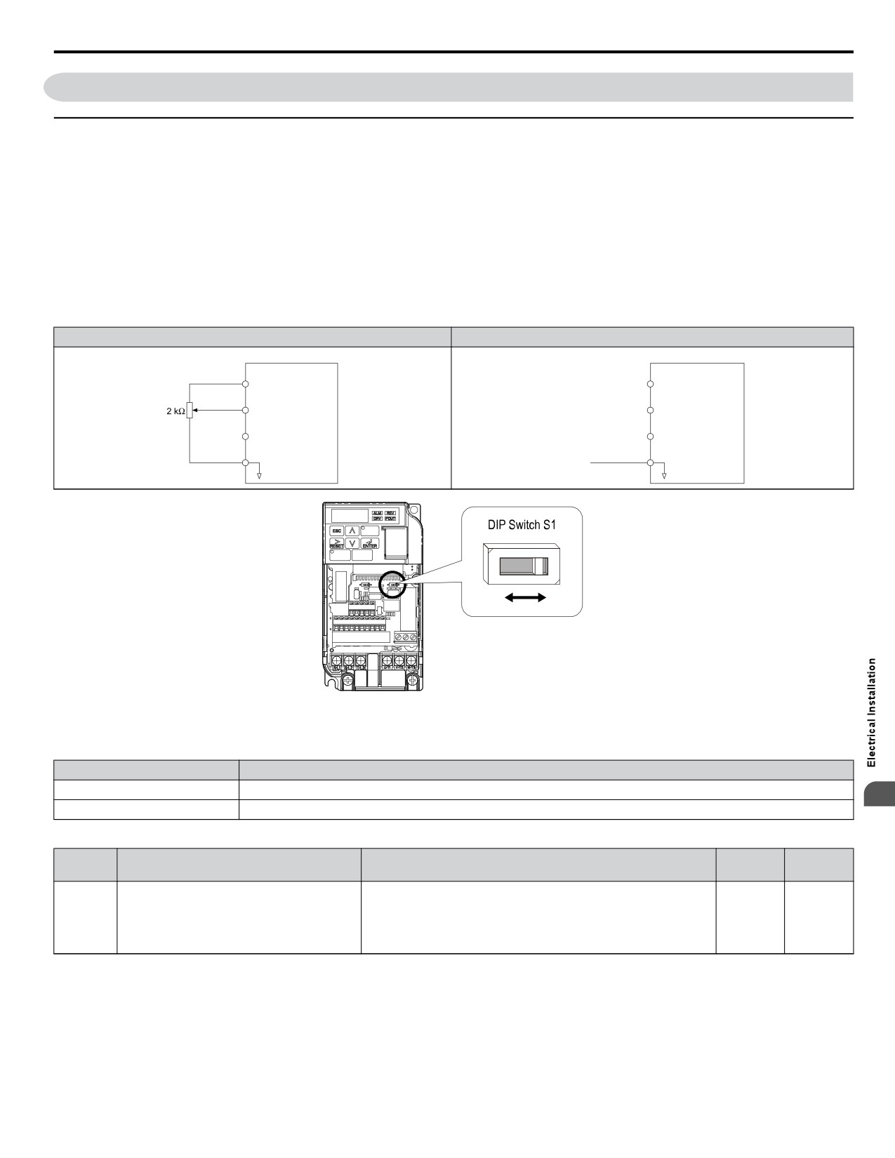
u DIP Switch S1 Analog Input Signal Selection
The main frequency reference can either be a voltage or current signal input. For voltage signals both analog inputs, A1 and
A2, can be used, for current signals A2 must be used.
When using input A2 as a voltage input, set DIP switch S1 to “V” (left position) and program parameter H3-09 to 0 (0 to +10
Vdc with lower limit) or 1 (0 to +10 Vdc without lower limit).
To use current input at terminal A2, set the DIP switch S1 to "I" (default setting) and set parameter H3-09 = 2 or 3 (4-20 mA
or 0-20 mA). Set parameter H3-10 = 0 (frequency reference).
Note:
If Terminals A1 and A2 are both set for frequency reference (H3-02 = 0 and H3-10 = 0), the addition of both input values builds the frequency
reference.
Table 3.14 Frequency Reference Configurations
Voltage Input
Current Input
Drive
Drive
+10.5 V
+10.5 V
+V
20 mA current
+V
20 mA current
0 to 10 V
Main speed
Main speed
A1
frequency reference
4 to 20 mA input
A1
frequency reference
(voltage input)
(voltage input)
or
Main speed
0 to 20 mA input
Main speed
A2 frequency reference
A2
frequency reference
(current input)
(current input)
AC
Frequency reference
AC
Frequency reference
common
common
V
I
Figure 3.27 DIP Switch S1
Table 3.15 DIP Switch S1 Settings
Setting Value
Description
V (left position)
Voltage input (0 to 10 V)
3
I (right position)
Current input (4 to 20 mA or 0 to 20 mA): default setting
Table 3.16 Parameter H3-09 Details
Setting
Default
No.
Parameter Name
Description
Range
Setting
Selects the signal level for terminal A2.
0: 0 to +10 V, unipolar input (with lower limit)
Frequency ref. (current)
H3-09
1: 0 to +10 V, bipolar input (no lower limit)
0 to 3
2
terminal A2 signal level selection
2: 4 to 20 mA
3: 0 to 20 mA
61
3.10 Wiring Checklist
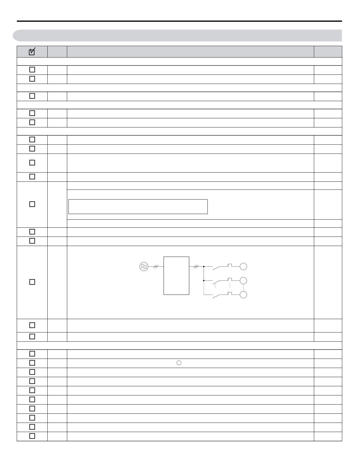
3.10
Wiring Checklist
No.
Item
Page
Drive, peripherals, option cards
1
Check drive model number to ensure receipt of correct model.
23
2
Check for correct braking resistors, DC link chokes, noise filters, and other peripheral devices.
-
Installation area and physical setup
3
Ensure area surrounding the drive complies with specifications.
28
Power supply voltage, output voltage
4
The voltage from the power supply should fall within the input voltage specification range of the drive.
-
5
The voltage rating for the motor should match the drive output specifications.
23
Main circuit wiring
6
Confirm proper branch circuit protection exists per National and Local codes.
40
7
Properly wire the power supply to drive terminals R/L1, S/L2 and T/L3.
-
Properly wire the drive and motor together.
8
The motor lines and drive output terminals R/T1, V/T2 and W/T3 should match in order to produce the desired
53
phase order. If the phase order is incorrect, the drive will rotate in the opposite direction.
9
Use 600 Vac vinyl-sheathed wire for the power supply and motor lines.
50
Use the correct wire gauges for the main circuit. Refer to Table 3.4, Table 3.5, or Table 3.6.
50
When using comparatively long motor cable, calculate the amount of voltage drop.
Motor rated voltage (V) x 0.02 ≥
10
50
3 x voltage resistance (Ω/km) x cable length (m) x motor rated current (A) x 10-3
If the cable between the drive and motor exceeds 50 m, adjust the carrier frequency (C6-02) accordingly.
53
11
Properly ground the drive.
53
12
Tightly fasten all terminal screws. Refer to Table 3.4, Table 3.5, or Table 3.6.
50
Set up overload protection circuits when running multiple motors from a single drive.
Power supply
Drive
MC1
OL1
M1
MC2
OL2
M2
13
-
MCn
OLn
Mn
MC1 - MCn ... magnetic contactor
OL 1 - OL n ... thermal relay
Note: Close MC1 through MCn before operating the drive.
If using a braking resistor or dynamic braking resistor unit, install a magnetic contactor. Properly install the resistor,
14
-
and ensure that overload protection shuts off the power supply.
15
Verify phase advancing capacitors are NOT installed on the output side of the drive.
-
Control circuit wiring
16
Use twisted-pair cables for all drive control circuit wiring.
-
17
Ground the shields of shielded wiring to the GND terminal.
57
18
If using a 3-Wire sequence, set parameters for MFDI terminals S1 through S7, and properly wire control circuits.
42
19
Check for any other wiring mistakes. Only use a multimeter to check wiring.
-
20
Properly fasten the control circuit terminal screws in the drive. Refer to Table 3.4, Table 3.5, or Table 3.6.
50
21
Pick up all wire clippings.
-
22
Ensure that no frayed wires on the terminal block are touching other terminals or connections.
-
23
Properly separate control circuit wiring and main circuit wiring.
-
24
Analog signal line wiring should not exceed 50 m.
-
25
Safe Disable Input wiring should not exceed 30 m.
-
62
4
Start-Up Programming & Operation
This chapter explains startup procedures and digital operator keypad functions, and gives instructions
on programming the drive for initial operation and other important functions.
4.1
SECTION SAFETY
64
4.2
DRIVE START-UP PREPARATION
66
4.3
POWERING UP THE DRIVE
68
4.4
USING THE STANDARD DIGITAL LED OPERATOR
69
4.5
THE DRIVE AND PROGRAMMING MODES
73
4.6
USING THE OPTIONAL HOA KEYPAD
74
4.7
PUMP APPLICATION PRESETS
86
4.8
IQPUMP PRESETS AND FUNCTIONS
87
4.9
AUTO-TUNING
101
4.10
NO-LOAD OPERATION TEST RUN
104
4.11
TEST RUN WITH LOAD CONNECTED
105
4.12
VERIFYING PARAMETER SETTINGS AND BACKING UP CHANGES
106
4.13
TEST RUN CHECKLIST
108
63
4.1 Section Safety
4.1
Section Safety
DANGER
Electrical Shock Hazard
Do not connect or disconnect wiring while the power is on.
Failure to comply will result in death or serious injury.
WARNING
Electrical Shock Hazard
Do not operate equipment with covers removed.
Failure to comply could result in death or serious injury.
The diagrams in this section may include drives without covers or safety shields to illustrate details. Be sure to reinstall
covers or shields before operating the drives and run the drives according to the instructions described in this manual.
Always ground the motor-side grounding terminal.
Improper equipment grounding could result in death or serious injury by contacting the motor case.
Do not touch any terminals before the capacitors have fully discharged.
Failure to comply could result in death or serious injury.
Before wiring terminals, disconnect all power to the equipment. The internal capacitor remains charged even after the power
supply is turned off. The charge indicator LED will extinguish when the DC bus voltage is below 50 Vdc. To prevent electric
shock, wait at least five minutes after all indicators are off and measure the DC bus voltage level to confirm safe level.
Do not allow unqualified personnel to perform work on the drive.
Failure to comply could result in death or serious injury.
Installation, maintenance, inspection, and servicing must be performed only by authorized personnel familiar with
installation, adjustment and maintenance of AC drives.
Do not perform work on the drive while wearing loose clothing, jewelry or without eye protection.
Failure to comply could result in death or serious injury.
Remove all metal objects such as watches and rings, secure loose clothing, and wear eye protection before beginning work
on the drive.
Do not remove covers or touch circuit boards while the power is on.
Failure to comply could result in death or serious injury.
Fire Hazard
Tighten all terminal screws to the specified tightening torque.
Loose electrical connections could result in death or serious injury by fire due to overheating of electrical connections.
Do not use an improper voltage source.
Failure to comply could result in death or serious injury by fire.
Verify that the rated voltage of the drive matches the voltage of the incoming power supply before applying power.
Do not use improper combustible materials.
Failure to comply could result in death or serious injury by fire.
Attach the drive to metal or other noncombustible material.
64
4.1 Section Safety
NOTICE
Observe proper electrostatic discharge procedures (ESD) when handling the drive and circuit boards.
Failure to comply may result in ESD damage to the drive circuitry.
Never connect or disconnect the motor from the drive while the drive is outputting voltage.
Improper equipment sequencing could result in damage to the drive.
Do not use unshielded cable for control wiring.
Failure to comply may cause electrical interference resulting in poor system performance. Use shielded twisted-pair wires
and ground the shield to the ground terminal of the drive.
Do not allow unqualified personnel to use the product.
Failure to comply could result in damage to the drive or braking circuit.
Carefully review instruction manual TOBP C720600 00 when connecting a braking option to the drive.
Do not modify the drive circuitry.
Failure to comply could result in damage to the drive and will void warranty.
Yaskawa is not responsible for any modification of the product made by the user. This product must not be modified.
Check all the wiring to ensure that all connections are correct after installing the drive and connecting any other
devices.
Failure to comply could result in damage to the drive.
4
65
4.2 Drive Start-Up Preparation
4.2
Drive Start-Up Preparation
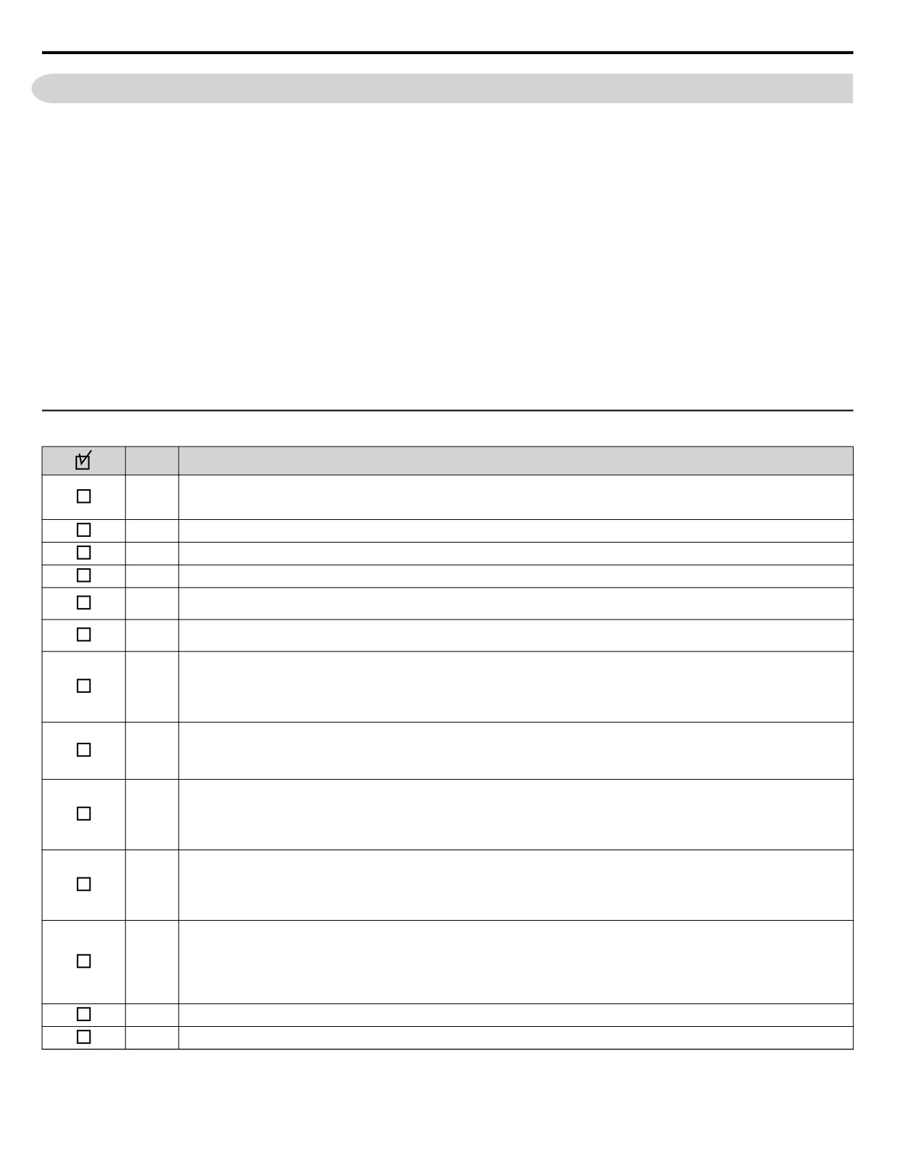
To provide the most reliable drive available and to avoid any extra costs related to loss or reduction of warranty coverage, an
authorized Yaskawa service representative should complete this start-up procedure. Please complete the following checklist
and maintain it in a secure location, as technical service personnel may request information from this checklist.
Note:
Refer to Powering Up the Drive on page 68 prior to powering up the drive for the first time.
Date:____________________________________________
Start-Up Person:
Company Name:_________________________________ Start-Up Location: _________________________________
Sales Order #: ___________________________________ Serial #: _________________________________________
Printed Name: ___________________________________ Drive Location: ___________________________________
Phone #: _______________________________________ Signature: _______________________________________
Owner’s Representative:
Printed Name: ___________________________________ Phone #: _________________________________________
Company: ______________________________________ Signature: ________________________________________
u Start-Up Checklist
No.
Item
The drive is thoroughly tested at the factory. The start up person should verify that the drive is free of shipping and installation damage.
1
Shipping damage is not covered by the Yaskawa warranty. Claims must be filed with the shipping company as soon as possible for
any potential recovery via insurance.
2
Review the Quick Start Procedure shipped with the drive.
3
Verify that the model number and voltage ratings in the purchase order match the nameplate data for each unit.
4
The location of the drive is important to achieve proper performance and normal operating life.
Ensure the drive is on a vertical surface with adequate space for air circulation. Refer to Correct Installation Spacing on page 29 for
5
proper spacing.
Verify that the proper branch circuit protection is installed in front of the drive. Refer to Factory Recommended Branch Circuit
6
Protection on page 430 for proper input fuse or circuit breaker sizing.
NOTICE: Separate control circuit wiring from main circuit wiring (terminals R/L1, S/L2, T/L3, B1, B2, U/T1, V/T2,
7
W/T3, Ջ, Պ1, Պ2) and other high-power lines. Improper wiring practices could result in drive malfunction due to
electrical interference.
NOTICE: Insulate shields with tape or shrink tubing to prevent contact with other signal lines and equipment.
8
Improper wiring practices could result in drive or equipment malfunction due to short circuit.
WARNING! Electrical Shock Hazard. Do not connect the AC power line to the output terminals of the drive. Failure
9
to comply could result in death or serious injury by fire as a result of drive damage from line voltage application to
output terminals.
NOTICE: Do not connect phase-advancing capacitors or LC/RC noise filters to the output circuits. Failure to comply
10
could result in damage to the drive, phase-advancing capacitors, LC/RC noise filters or ground fault circuit
interrupters.
Use crimp insulated terminals or insulated shrink tubing for wiring connections. Wires should have a continuous maximum allowable
temperature of 75 °C 600 Vac UL-approved vinyl-sheathed insulation.
Consider the amount of voltage drop when selecting wire gauges. Increase the wire gauge when the voltage drop is greater than 2%
11
of motor rated voltage. Ensure the wire gauge is suitable for the terminal block. Use the following formula to calculate the amount of
voltage drop:
Line drop voltage (V) = 3 × wire resistance (Ω/km) × wire length (m) × current (A) × 10-3
12
If the cable between the drive and motor exceeds 50 m (164 ft.), adjust the carrier frequency set C6-02 accordingly.
13
Determine proper wire size for power and motor leads.
66
4.2 Drive Start-Up Preparation
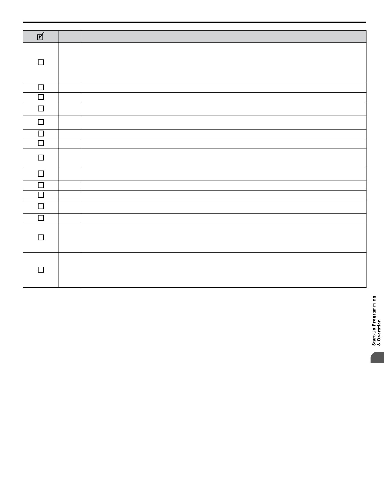
No.
Item
WARNING! Always ground the ground terminal. (200 V Class: Ground to 100 Ω or less, 400 V Class: Ground to
10 Ω or less). Improper equipment grounding could result in death or serious injury by contacting ungrounded
14
electrical equipment.
When using multiple drives, ground each drive directly or daisy-chain to the ground pole(s). DO NOT FORM A LOOP WITH THE
GROUND LEADS. Refer to Multiple Drive Wiring on page 54.
15
Review terminal functions of signal and control circuits.
16
Verify if any customer safety devices are required (e.g. External Pump Fault).
Record the following motor nameplate information:
17
Voltage: _____________________Motor Rated Amps: ____________________
Verify that the commercial power supply is within the rated drive input voltage:
18
Power Supply: ____________________Vac Drive Input Voltage: ____________________Vac
19
Determine whether three-phase input power or single-phase input power is to be used.
20
Verify that the leads in the three-phase electric motor conduit box are configured for the proper voltage.
Ensure Motor Rated Current is less than or equal to drive output amps. If multiple motors are being used, make sure that the Motor
21
Rated Current sum is less than or equal to drive output amp rating. Please note that if multiple motors are being operated from one
drive, each motor must have its own overload and short circuit protection.
Wire all necessary power leads to the drive.
22
DO NOT CONNECT MOTOR TO DRIVE AT THIS TIME.
23
Wire all necessary ground wires to the drive.
24
Wire all necessary control wires to the drive.
Ensure that the power leads are connected to the R/L1, S/L2 and T/L3 terminals in the drive. Confirm single-phase input or three-
25
phase input wiring.
26
Tighten all of the three-phase power and ground connections. Please check that all control and signal terminations are tight.
Inspect the control circuit connections (including the shield) and determine if a motor safety circuit is connected. If normally closed,
these contacts may be wired in series with the RUN command contacts, which are between terminals S1 and SN of the drive. No
27
special programming is required.
Alternately, these contacts could be wired between terminals S3 and SN as External Fault Inputs, and may be either normally closed
or normally open contacts.
Record any other connections to the drive to determine if special programming is required for the following:
Multi-function Inputs
Multi-function Outputs
28
Multi-function Digital Inputs
Multi-function Analog Outputs
Network Communications
4
67
4.3 Powering Up the Drive
4.3
Powering Up the Drive
u Powering Up the Drive and Operation Status Display
n Powering Up the Drive
Review the following checklist before turning the power on.
Item to Check
Description
Ensure the power supply voltage is correct:
200 V class: single-phase 200 to 240 Vac 50/60 Hz
200 V class: 3-phase 200 to 240 Vac 50/60 Hz
400 V class: 3-phase 380 to 480 Vac 50/60 Hz
Power supply voltage
Properly wire the power supply input terminals (R/L1, S/L2, T/L3).
(for single-phase 200 V class models, wire only R/L1 and S/L2)
Check for proper grounding of drive and motor.
Drive output terminals
Properly wire drive output terminals U/T1, V/T2, and W/T3 with motor terminals U, V, and W.
and motor terminals
Control circuit terminals
Check control circuit terminal connections.
Drive control terminal status
Open all control circuit terminals (off).
Status of the load
Uncouple the motor from the load.
and connected machinery
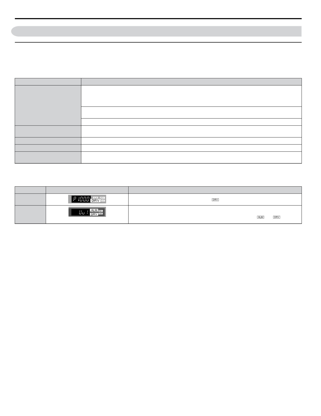
n Status Display
When the power supply to the drive is turned on, the LED operator lights will appear as follows:
No.
Name
Description
Normal
The data display area displays the setpoint.
is lit.
Operation
Data displayed varies by the type of fault. Refer to Fault Displays, Causes, and Possible
Fault
Solutions on page 253 for more information and possible solution.
and
are lit.
Main circuit low voltage (ex)
Note:
Display will vary depending on drive settings.
STO
68
4.4 Using the Standard Digital LED Operator
4.4
Using the Standard Digital LED Operator
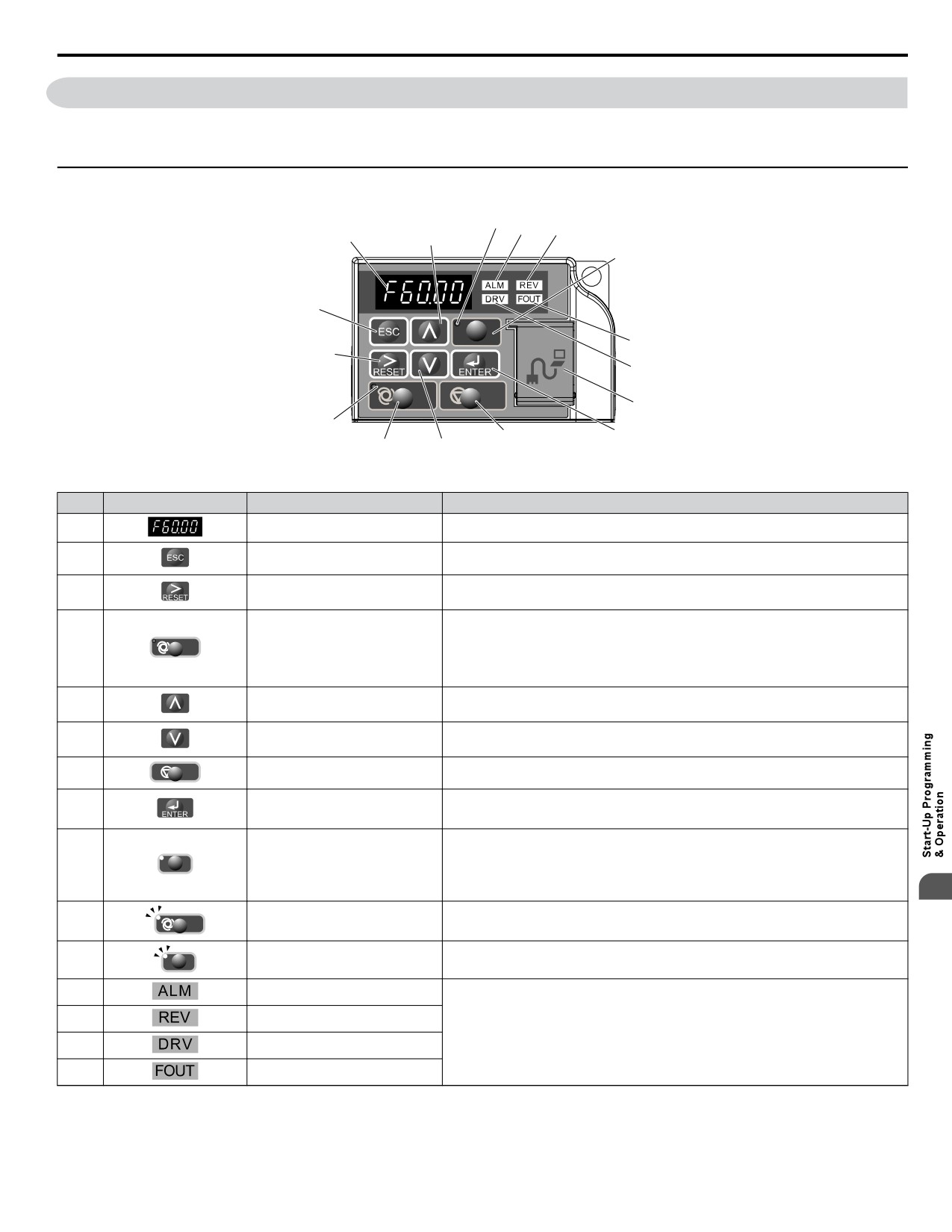
Use the LED operator to enter run and stop commands, display data, edit parameters, as well as display fault and alarm
information.
u Keys, Displays, and LEDs
11
12
13
1
5
9
2
HAND
15
3
14
AUTO
OFF
16
10
8
7
4
6
Table 4.1
Keys and Displays on the LED Operator
No.
Display
Name
Function
1
Data Display Area
Displays the setpoint, frequency reference, parameter number, etc.
2
ESC Key
Returns to the previous menu.
Moves the cursor to the right.
3
RESET Key
Resets the drive to clear a fault situation.
Selects the source of Run command and frequency reference.
• Set the drive to AUTO mode.
4
AUTO
AUTO Key
• Run command input source depends on b1-02.
• Frequency reference input source depends on b1-01.
Scrolls up to display the next item, selects parameter numbers, and increments
5
Up Arrow Key
setting values.
Scrolls down to display the previous item, selects parameter numbers, and
6
Down Arrow Key
decrements setting values.
7
OFF
OFF Key
Follows the stopping method set in b1-03 to stop drive operation.
• Enters parameter values and settings.
8
ENTER Key
• Selects a menu item to move between displays.
The drive runs at a selectable frequency reference source as set by P5-01.
• Set the drive to HAND mode.
9
HA
HAND Key
• When P5-03 is set to 1, HAND and AUTO mode can be switched while the drive
is running.
4
10
AUTO
AUTO Light
Lit while the drive is in AUTO mode. Refer to page 70 for details.
11
HAND Light
Lit while the drive is in HAND mode. Refer to page 70 for details.
HAND
12
ALM LED Light
13
REV LED Light
Refer to LED Screen Displays on page 70.
14
DRV LED Light
15
FOUT LED Light
69
4.4 Using the Standard Digital LED Operator
No.
Display
Name
Function
Port used for USB Copy Unit, LCD Operator Keypad, and for connecting to a PC.
NOTICE: Use only specified cable when making connections to the drive.
Failure to comply may damage the drive.
16
-
Communication Port
NOTICE: Do not open the port cover wider than 90 degrees. Failure to
comply may break the port cover and leave the unprotected port susceptible
to damage.
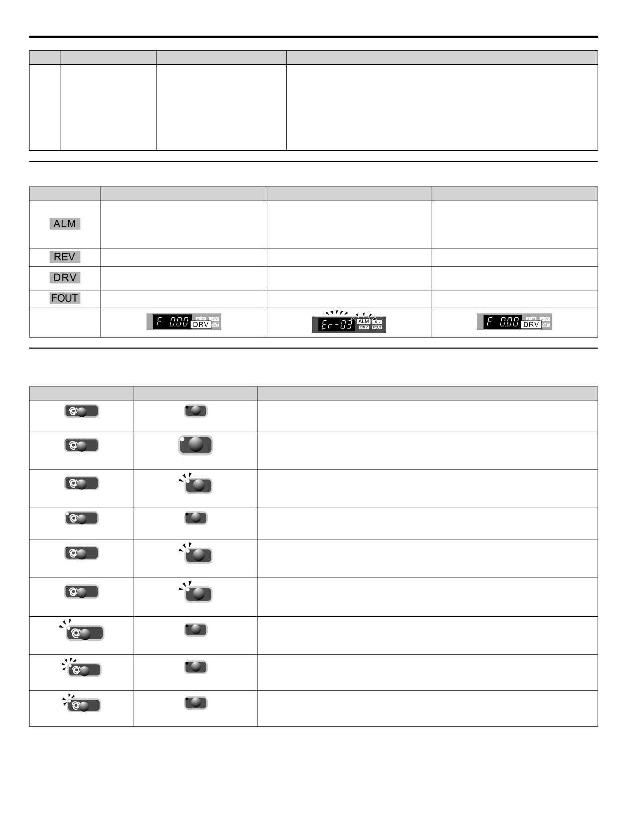
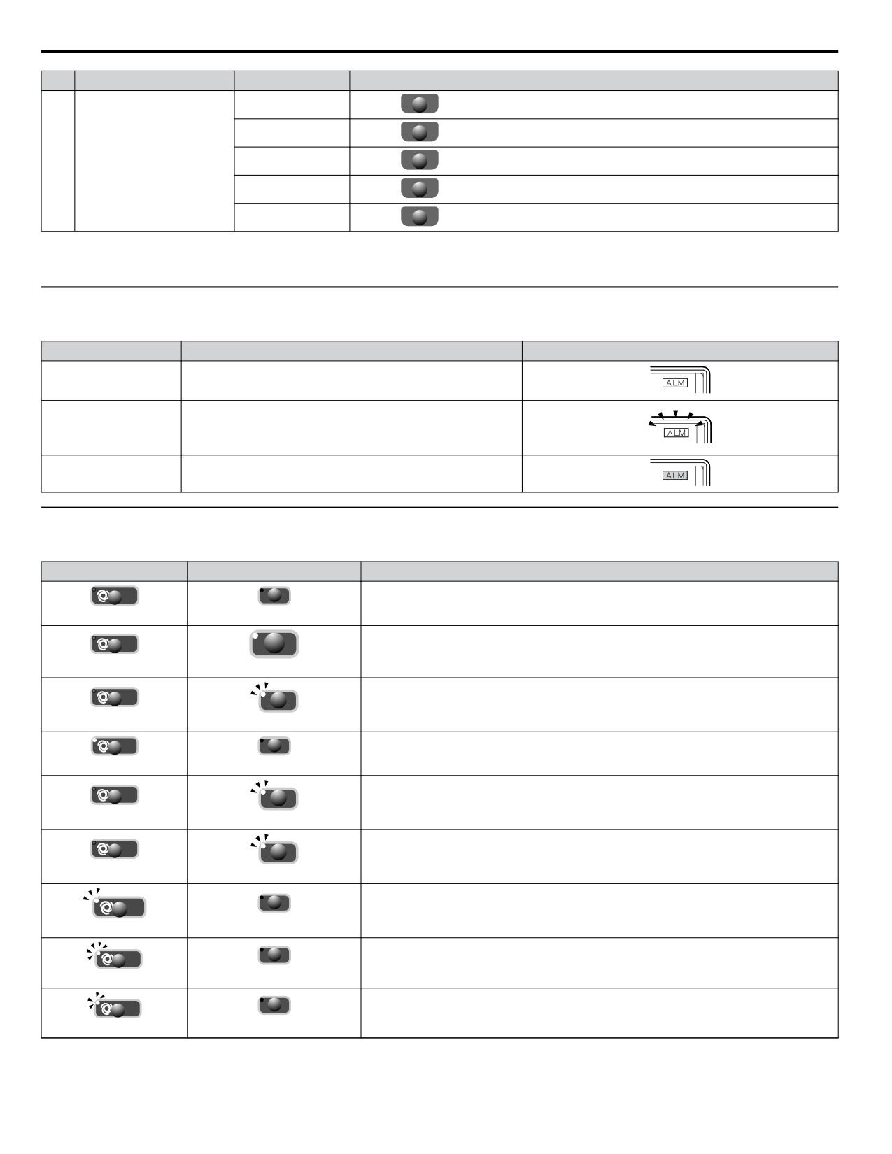
u LED Screen Displays
Display
Lit
Flashing
Off
•
When an alarm occurs
•
oPE detected
When the drive detects an alarm or error
Normal state (no fault or alarm)
•
When a fault or error occurs during
Auto-Tuning
Motor is rotating in reverse
—
Motor is rotating forward
Drive Mode
Programming Mode
Auto-Tuning
Displays output frequency (Hz)
—
—
As illustrated in
this manual
u AUTO LED and HAND LED Indications
STO
Table 4.2
AUTO LED and HAND LED Indications
AUTO LED
HAND LED
State
AUTO
HAN
OFF mode
Off
Off
AUTO
HAN
HAND mode (Also during DC injection braking)
Off
On solid
AUTO
HAND mode when the Frequency Reference is 0 and/or decelerating in HAND mode, or
HAND
during PI Sleep or Snooze.
Off
Long blink (50% duty)
AUTO
HAN
Running in AUTO mode (Also during DC injection braking)
On solid
Off
AUTO
HAND mode, Ready, No Run command input.
HAND
Off
Note:
Short Blink for Legacy Operation Mode (S5-04 = 0).
Short blink (15% duty)
AUTO
HAND
HAND mode, cycle the Run command.
Off
Double blink
AUTO
HAND
Running in AUTO mode when the Frequency Reference is 0 and/or decelerating in AUTO
mode, or during PI Sleep or Snooze.
Off
Long blink (50% duty)
AUTO
HAND
AUTO mode, Ready, No run command input.
Off
Short blink (15% duty)
AUTO
HAND
AUTO mode, stopped by a Fast- Stop from a Multi-Function Digital Input.
Double blink
Off
70
4.4 Using the Standard Digital LED Operator
2 s
1 s
ON
ON
ON
Long blink
(50% dut y)
ON
ON
ON
ON
ON
ON
Double blink
ON
ON
Short link
(15% dut y)
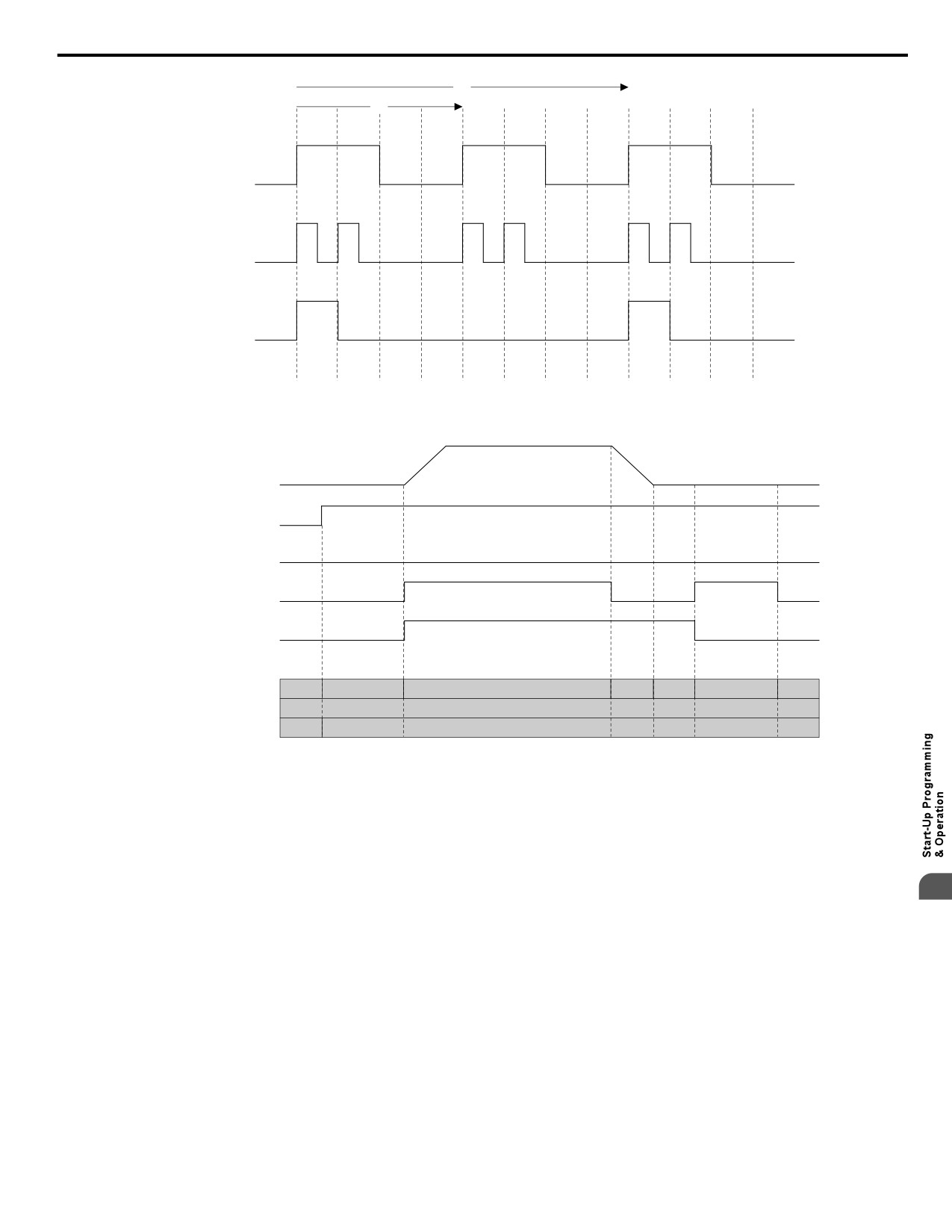
Figure 4.1 AUTO LED and HAND LED Timing Status
Output Frequency
AUTO Mode Selection
HAND Mode Selection
OFF
ON
RUN Command
6 Hz
0 Hz
Frequency
AUTO LED
OFF
Short blink
ON
Blink
OFF
Blink
OFF
HAND LED
OFF
Operation Mode
OFF
AUTO
Figure 4.2 LEDs and Drive Operation in AUTO and HAND Modes
4
71
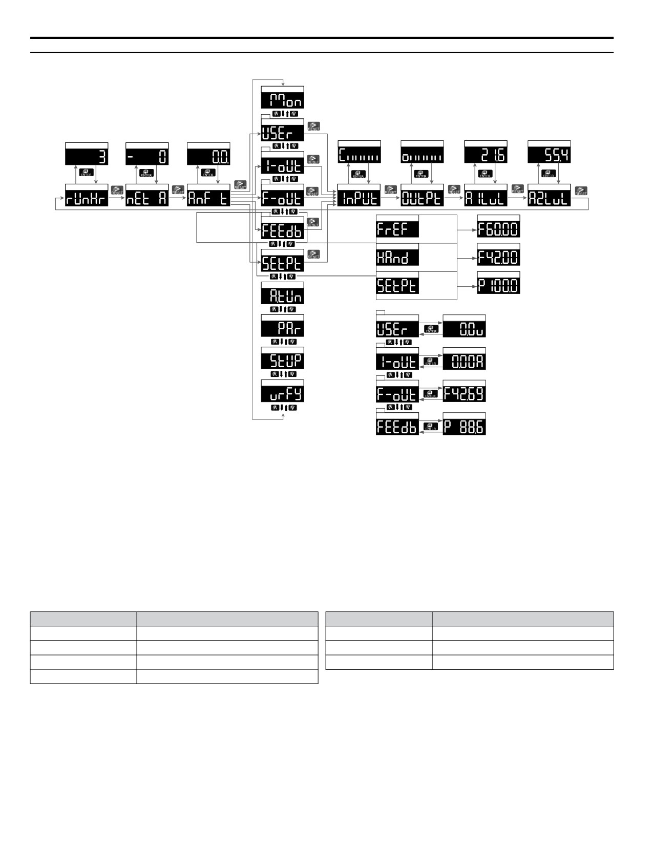
4.4
Using the Standard Digital LED Operator
u Menu Structure for Digital LED Operator
Monitor Menu
<1>
User Selected Monitor
U4-01
U9-02
U1-99
U1-10
U1-11
U1-13
U1-14
<2>
Current Output
1.25 s
1.25 s
1.25 s
<3>
1.25 s
1.25 s
1.25 s
1.25 s
Drive Oper Time Hrs
iQ Network
Activity
Anti-No-Flow Timer
Output Frequency
Digital Input Status
Digital Output Status
A1 Input Level
A2 Input Level
<4>
Frequency Reference
U1-01
Skipped when
PID Feedback
PID
b5-01 =0
Disabled
1.25 s
(PID Disabled)
not in HAND
Home Screen:
HAND Reference
U1-01
PID Setpoint
1.25 s
Changes
HAND Mode
depending on
Mode
PID Setpoint
U5-99
PID
Auto-Tuning
Enabled
1.25 s
not in HAND
<1>
Parameters
User Selected Monitor
1.25 s
o1-01 Selected
<2>
Quick Setting
Current Output
1.25 s
U1-03
<3>
Modified Constants
Output Frequency
1.25 s
U1-02
<4>
PID Feedback
1.25 s
U5-01
Figure 4.3
Digital LED Operator Screen Structure
n
Home Quick Monitor Display (LED)
The Home Quick Monitor provides an easily accessible preset group of monitors that are frequently used during operation.
FREF or SETPT - U1-01, Frequency Reference, or U5-99, AUTO Setpoint
FEEDB - U1-91, PID Feedback
F-OUT - U1-02, Output Frequency
I-OUT - U1-03, Output Current
USER - Selected Monitor via o1-01 (defaulted to U1-06 Output Voltage)
The following monitors are available via the Quick Monitor:
Monitor
Name
Monitor
Name
U1-10
Input Terminal Status
U4-01
Drive Elapsed Time
U1-11
Output Terminal Status
U9-02
iQ Network Activity
U1-13
Terminal A1 Level
U1-99
Anti-No-Flow Timer
U1-14
Terminal A2 Level
When navigating through the preset monitors at the Main Menu or the Quick Monitors, a 5-character descriptive text appears
briefly before showing the monitor values.
When viewing a Quick Monitor value, press ENTER to re-display the 5-character descriptive text for a brief time. Press ESC
when the Quick Monitor value is displayed to jump to the U1-01, Frequency Reference/U5-99, AUTO Setpoint, monitor.
The PID Setpoint unit is animated with alternating “P” and “S”. The PID Setpoint unit is not shown when the value rises above
4 digits or when in Non-MOP parameter entry mode (Q1-oo to U5-99)
The PID Feedback unit is animated with a P alternating with a rising level. The PID Feedback unit is not shown when the
value rises above 4 digits.
72
4.5 The Drive and Programming Modes
4.5
The Drive and Programming Modes
The drive functions are divided into two main groups accessible via the digital LED operator:
Drive Mode: The Drive mode allows motor operation and parameter monitoring. Most parameter settings cannot be changed
when accessing functions in the Drive Mode.
Programming Mode: The Programming Mode allows access to setup/adjust, verify parameters and Auto-Tuning. The drive
prohibits changes in motor operation such as start/stop when the Digital LED Operator is accessing a function in the
Programming Mode.
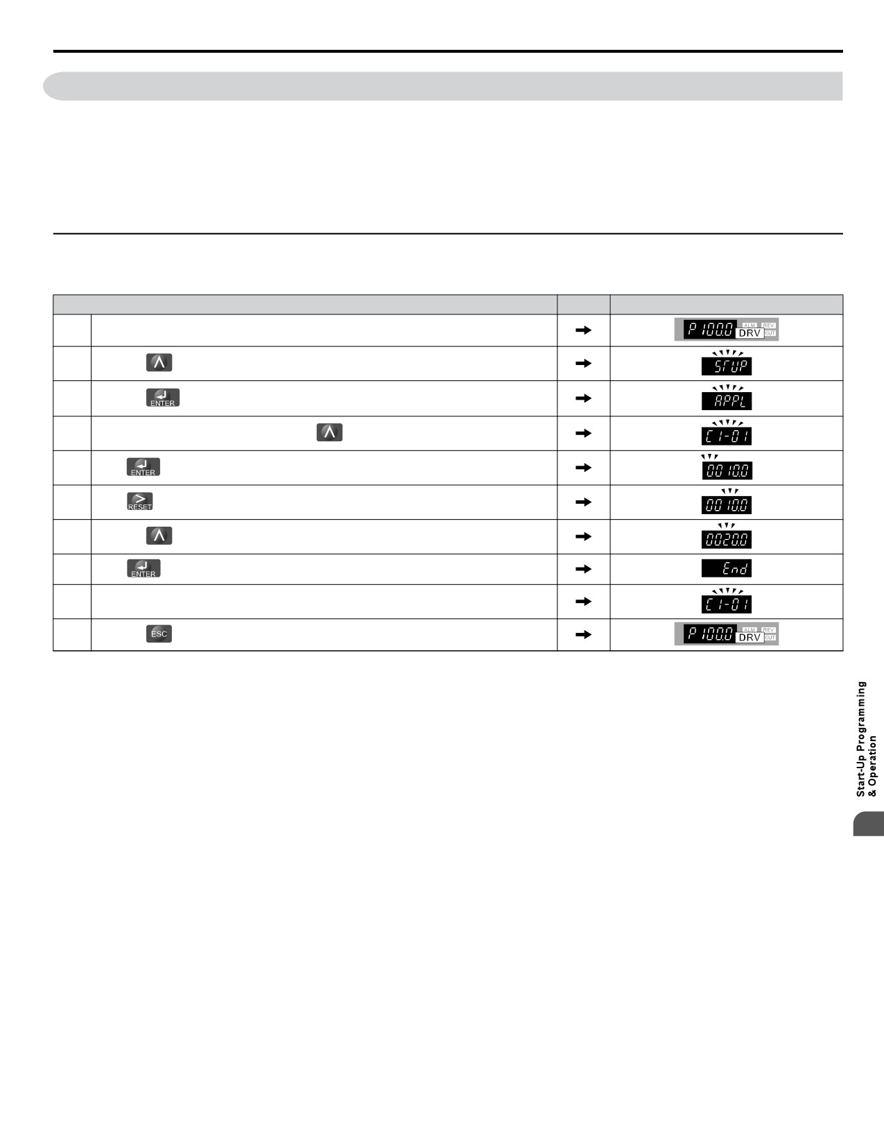
u Changing Parameter Settings or Values
This example explains changing C1-01, Acceleration Time 1, from 10.0 seconds to 20.0 seconds.
Step
Display/Result
1.
Turn on the power to the drive. The initial display appears.
2.
Press the
key until the Setup Mode Screen appears.
3.
Press the
key to view the parameter setting display.
4.
Scroll through parameters by pressing the
key until C1-01 appears.
5.
Press
to view the current setting value (10.0). (Number farthest to the left flashes)
6.
Press
until the desired number is selected. (“1” flashes)
7.
Press the
key and enter 0020.0.
8.
Press
and the drive will confirm the change.
9.
The display automatically returns to the screen shown in Step 4.
10.
Press the
key until back at the initial display.
4
73
4.6 Using the Optional HOA Keypad
4.6
Using the Optional HOA Keypad
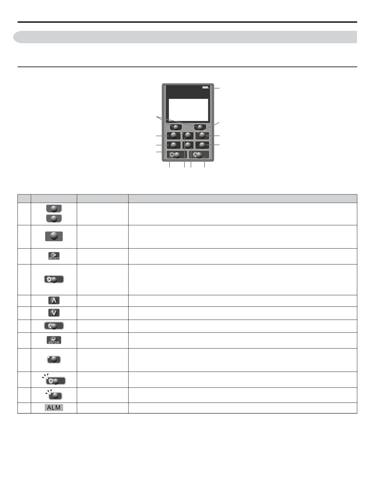
Use the HOA keypad to enter OFF commands, switch AUTO or HAND Mode, change parameters, and display data including
fault and alarm information.
u Keys and Displays
DIGITAL OPERATOR JVOP-183
ALM
12
1
11
F1
F2
M
M
2
ESC
HAND
9
3
RE
SET
ENTER
8
10
AUTO
OFF
4
5 6
7
Figure 4.4 Keys and Displays on the HOA Keypad
No.
Display
Name
Function
F1
Function Key
The functions assigned to F1 and F2 vary depending on the currently displayed menu. The name of
1
(F1, F2)
each function appears in the lower half of the display window.
F2
• Returns to the previous display.
2
ESC
ESC Key
• Moves the cursor one space to the left.
• Pressing and holding this button will return to the Frequency Reference display.
• Moves the cursor to the right.
3
RESET Key
• Resets the drive to clear a fault situation.
Selects the source of Run command and frequency reference.
• Set the drive to AUTO mode.
4
AUTO
AUTO Key
• Run command input source depends on b1-02.
• Frequency reference input source depends on b1-01.
5
Up Arrow Key
Scrolls up to display the next item, selects parameter numbers, and increments setting values.
6
Down Arrow Key
Scrolls down to display the previous item, selects parameter numbers, and decrements setting values.
7
OFF
OFF Key
Follows the stopping method set in b1-03 to stop drive operation.
• Enters parameter values and settings.
8
ENTER Key
• Selects a menu item to move between displays.
The drive runs at a selectable frequency reference source as set by P5-01.
9
HA
HAND Key
• Set the drive to HAND mode.
• When P5-03 is set to 1, HAND and AUTO mode can be switched while the drive is running.
10
AUTO
AUTO Light
Lit while the drive is in AUTO mode. Refer to page 70 for details.
11
HAND Light
Lit while the drive is in HAND mode. Refer to page 70 for details.
HAND
12
ALM LED Light
Refer to ALARM (ALM) LED Displays on page 76 for details.
74
4.6 Using the Optional HOA Keypad
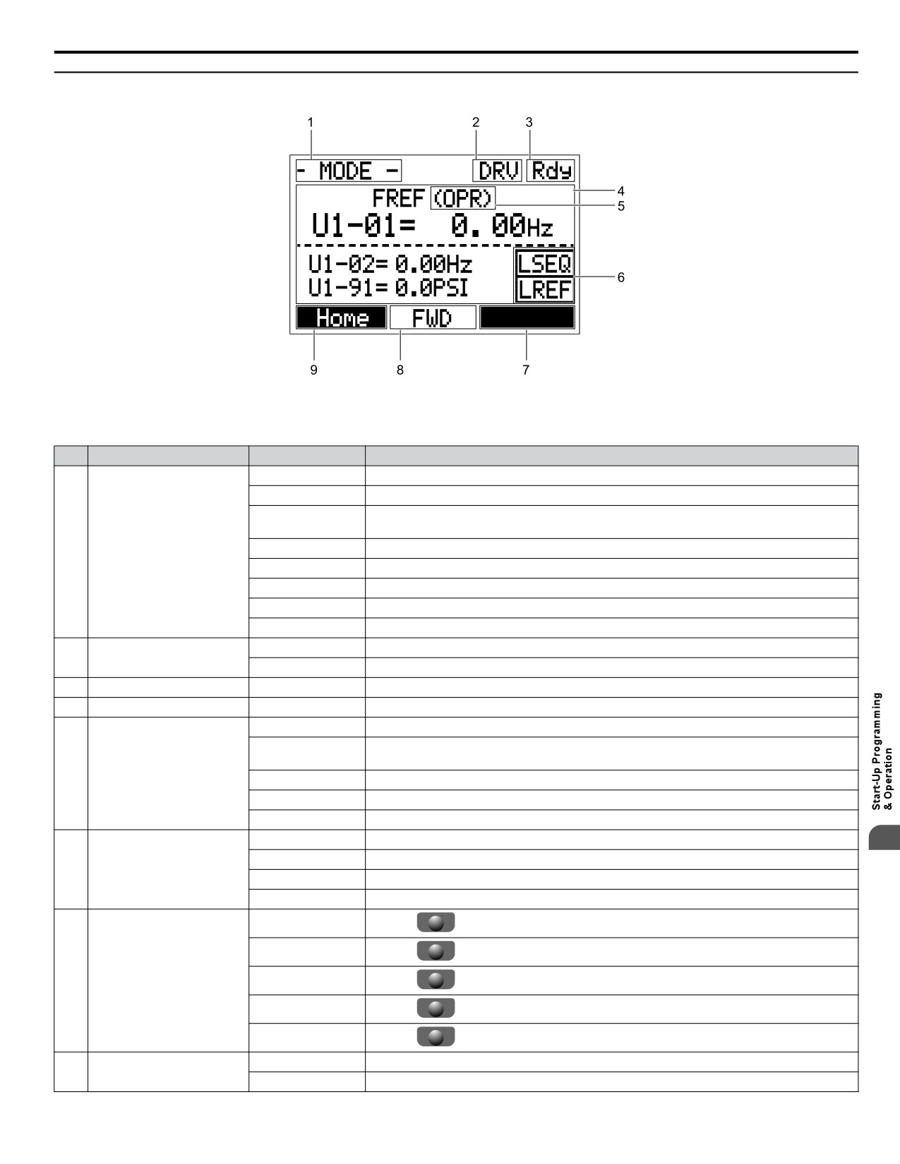
u LCD Display
Figure 4.5 LCD Display
Table 4.3 Display and Contents
No.
Name
Display
Content
MODE
Displayed when in Mode Selection.
QMONI: Use F1/F2
Instructions to access the Quick Monitors.
MENU: Use UP/
Instructions to access the next menu item.
DWN
MONITR
Displayed when in Monitor Mode.
1
Operation Mode Menus
VERIFY
Indicates the Verify Menu.
PRMSET
Displayed when in Parameter Setting Mode.
A.TUNE
Displayed during Auto-Tuning.
SETUP
Displayed when in Setup Mode.
DRV
Displayed when in Drive Mode.
2
Mode Display Area
PRG
Displayed when in Programming Mode.
3
Ready
Rdy
Indicates the drive is ready to run.
4
Data Display
—
Displays specific data and operation data.
OPR
Displayed when the frequency reference is assigned to the HOA keypad.
Displayed when the frequency reference is assigned to the MEMOBUS/Modbus
COM
Frequency
Communication Inputs of the drive.
5
Reference
OP
Displayed when the frequency reference is assigned to option card connected to the drive.
Assignment <1>
AI
Displayed when the function reference is assigned to an analog input.
OFF
Displayed when HAND mode is OFF.
RSEQ
Blinks when the Run command is supplied from a remote source.
4
LOCAL/REMOTE
LSEQ
Displayed when the Run command is supplied from the HOA keypad.
6
Display <2>
RREF
Blinks when the Run command is supplied from a remote source.
LREF
Displayed when the Run command is supplied from the HOA keypad.
<-MONITOR->
Pressing F2
displays the next Quick Monitor.
DATA
Pressing F2
scrolls to the next display.
Function Key 2
7
→
(F2)
Pressing F2
scrolls the cursor to the right.
RESET
Pressing F2
resets the existing drive fault error.
Monitor
Pressing F2
switches Monitor mode.
FWD
Indicates forward motor operation.
8
FWD/REV
REV
Indicates reverse motor operation.
75
4.6 Using the Optional HOA Keypad
No.
Name
Display
Content
<-MONITOR->
Pressing F1
displays the previous Quick Monitor.
←
Pressing F1
scrolls the cursor to the left.
Function Key 1
9
Home
(F1)
Pressing F1
returns to the top menu (Frequency Reference).
ESC
Pressing F1
returns to the previous display.
Monitor
Pressing F1
switches Monitor mode.
<1> Displayed when in Frequency Reference Mode.
<2> Displayed when in Frequency Reference Mode and Monitor Mode.
u ALARM (ALM) LED Displays
Table 4.4 ALARM (ALM) LED Status and Contents
State
Content
Display
Illuminated
When the drive detects an alarm or error.
• When an alarm occurs.
Flashing
• When an oPE is detected.
• When a fault or error occurs during Auto-Tuning.
Off
Normal operation (no fault or alarm).
u AUTO LED and HAND LED Indications
Table 4.5
AUTO LED and HAND LED Indications
AUTO LED
HAND LED
State
AUTO
HAN
OFF mode
Off
Off
AUTO
HAN
HAND mode (Also during
DC injection braking)
Off
On solid
AUTO
HAND mode when the Frequency Reference is 0 and/or decelerating in HAND mode, or
HAND
during PI Sleep or Snooze.
Off
Long blink (50% duty)
AUTO
HAN
Running in AUTO mode (Also during DC injection braking)
On solid
Off
AUTO
HAND mode, Ready, No Run command input.
HAND
Off
Note:
Short Blink for Legacy Operation Mode (S5-04 = 0).
Short blink (15% duty)
AUTO
HAND
HAND mode, cycle the Run command.
Off
Double blink
AUTO
HAND
Running in AUTO mode when the Frequency Reference is 0 and/or decelerating in AUTO
mode, or during PI Sleep or Snooze.
Off
Long blink (50% duty)
AUTO
HAND
AUTO mode, Ready, No run command input.
Short blink (15% duty)
Off
AUTO
HAND
AUTO mode, stopped by a Fast- Stop from a Multi-Function Digital Input.
Off
Double blink
76
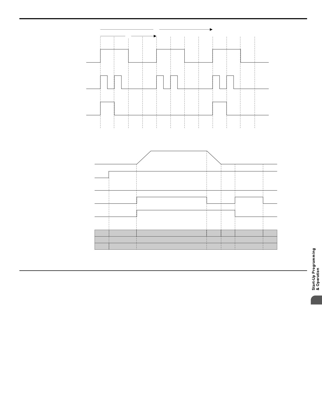
4.6 Using the Optional HOA Keypad
2 s
1 s
ON
ON
ON
Long blink
(50% dut y)
ON
ON
ON
ON
ON
ON
Double blink
ON
ON
Short link
(15% dut y)
Figure 4.6 AUTO LED and HAND LED Timing Status
Output Frequency
AUTO Mode Selection
HAND Mode Selection
OFF
ON
RUN Command
6 Hz
0 Hz
Frequency
AUTO LED
OFF
Short blink
ON
Blink
OFF
Blink
OFF
HAND LED
OFF
Operation Mode
OFF
AUTO
Figure 4.7 LEDs and Drive Operation in AUTO and HAND Modes
u Setting the Real Time Clock
The time and date must be set when a new HOA keypad is plugged in and the drive is powered up. The HOA keypad will
display the time and date setup screen for 30 seconds. If a button is not pressed during this time, the display will clear and a
“Clock Not Set” alarm will flash. Pressing the F2 (Data) key will display the setting screen again.
4
n Feedback Loss Wire Break Alarm
If there is no sensor wired to the drive, a “Feedback Loss - Wire Break” alarm will flash on the display. Providing the proper
feedback device signal will clear the Feedback Loss alarm.
The drive requires a feedback device (e.g., pressure transducer, flow meter, etc.) to perform automatic system regulation. Any
analog 0~10 V or 4-20 mA feedback device can be used in combination with the drive.
Note:
The factory default setting for the drive is 4~20 mA feedback device connected to analog input A2.
n Real Time Clock Setting Display
Note:
Setting the Real-Time Clock will clear a “Clock Not Set” alarm.
77
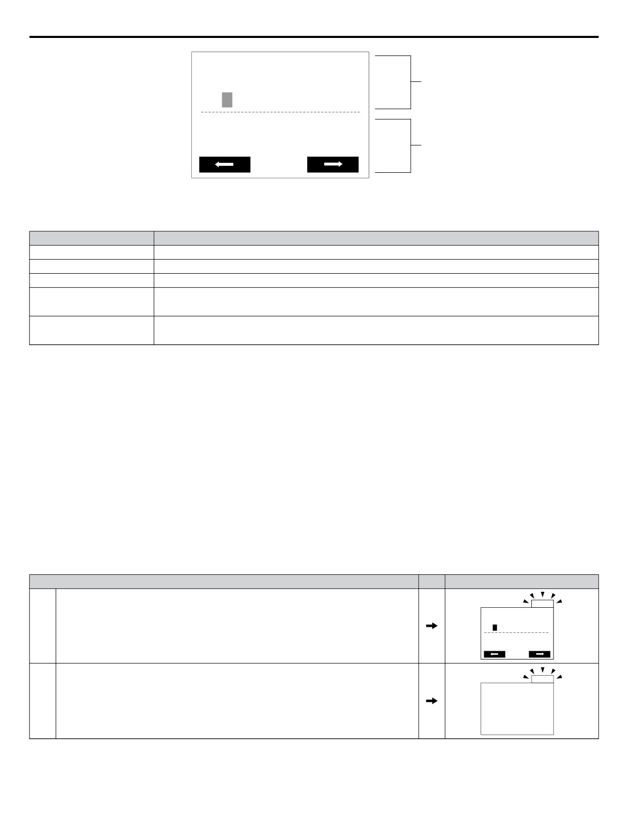
4.6 Using the Optional HOA Keypad
YYYY/MM/DD HH:MM
A
20 10/01/01 00:00
Second per month
+ 0 sec
B
A - Real Time Clock Setting Display
B - Gain/Loss Adjustment Display
Set in 24-Hour Clock Time
Figure 4.8 Real Time Clock Adjustment Display
Display
Description
YYYY
Set the year with the last two digits.
MM
Set the month with two digits.
DD
Set the day with two digits.
Set the hours and minutes, with two digits for each.
HH:MM
Note:
Set in 24-hour clock time. After initial setup, the time will display in 12-hour clock time.
Set the gain or loss in seconds per month.
Second per month
Note:
This does not need to be set for the RTC to function properly.
Moving the Cursor
Pressing the F2 key or the RESET key will move the cursor to the digit on the right. Pressing the F1 key will move the cursor
to the left.
Changing Settings
• Changing YYYY/MM/DD HH:MM: Pressing the up arrow key will increase the number selected by the cursor from 0 to
9. Pressing the down arrow key will decrease the number selected by the cursor from 0 to 9.
• Setting the Seconds per Month: This setting does not need to be adjusted. Pressing the up arrow key will increase the
number selected by the cursor from -504 to +488 in increments of 8. Pressing the down arrow key will decrease the number
selected by the cursor from -504 to +488 in increments of 8.
The feature is used to keep the RTC in sync with an external device clock, like a PLC or BAS system, and will adjust the
clock by a set amount of seconds every month.
n Real-Time Clock Setting at Initial Power-up of a New Drive
Setting the Real-time clock is required at power-up of a new HOA operator or after digital operator battery replacement.
Table 4.6 illustrates how to set the Real-Time Clock at initial power-up of a new drive.
Table 4.6 Clock Adjustment Procedure at Power-up of a New Drive
Procedure
Display
ALM
Turn the power on. The Real Time Clock Adjustment Display will appear. Use the right arrow
YYYY/MM/DD HH:MM
1
key to select the desired digit, then set the correct date and 24-hour clock time using the up and
20 10/01/01 00:00
down arrow keys.
Second per month
+ 0 sec
ALM
After entering the Real-Time Clock data, press the ENTER key to save the changes.
2
The display will indicate “Entry Accepted” and return to the initial display in step 3 and the alarm
Entry accepted
LED will be OFF.
78
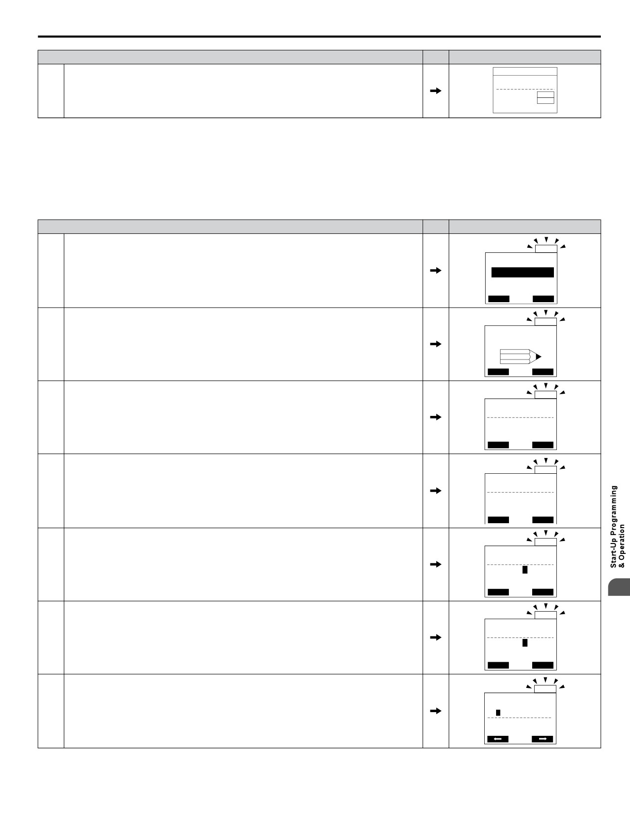
4.6 Using the Optional HOA Keypad
Procedure
Display
- MODE -
DRV Rdy
Auto Setpoint
U5-99= 0.0PSI
3
Initial display.
U1-02= 0.00Hz
LSEQ
U1-91= 0.0PSI
LREF
<-MONITOR->
n Manual Clock Adjustment by Setting o4-17 to 1
The following actions are possible in the Clock Adjustment Mode:
• Set the current time
• Check the time set to the drive Real-Time Clock
Table 4.7 illustrates how to set the Real-Time Clock manually.
Table 4.7 Manual Clock Adjustment Procedure by Setting o4-17 to 1
Procedure
Display
ALM
- MODE -
DRV Rdy
The “Clock Not Set” display will appear if the Real-Time Clock data is not entered within 30
1
Clock Not Set
seconds of power-up of a drive with an HOA operator that has not yet been set.
Press F2 to Set
FWD
DATA
ALM
- MODE -
PRG
Use the up and down arrow keys to scroll through display menu until the screen shows
Programming
2
“Programming”.
HOME FWD
ALM
- PRMSET - PRG
Initialization
3
Press the ENTER key to enter select the parameter setting mode.
A1-00 = 0
Select Language
HOME
FWD
DATA
ALM
- PRMSET - PRG
Maintenance
4
Use the up and down arrow keys to scroll through display menu until parameter o4-17 appears.
o4-17 = 0
Set time
HOME
FWD
DATA
ALM
- PRMSET - PRG
Set time
5
Press the ENTER key until “0” flashes.
o4-17= 0 *0*
- -
“0”
HOME
FWD
DATA
4
ALM
- PRMSET - PRG
Set time
6
Press the up arrow key so that the display changes to “1”.
o4-17= 1 *0*
Set
“0”
HOME
FWD
DATA
ALM
Press the ENTER key and the time setting screen will appear. Use the right arrow key to select
YYYY/MM/DD HH:MM
7
20 10/01/01 00:00
the desired digit, then set the correct date and time using the up and down arrow keys.
Second per month
+ 0 sec
79
4.6 Using the Optional HOA Keypad
Procedure
Display
ALM
After entering the correct time, press the ENTER key to save the changes.
8
The display will return to the display shown in step 5 and the alarm LED will be OFF.
Entry accepted
n o4-17: Real-Time Clock Setting (Resetting RTC to Factory Default)
No.
(Addr.
Name
Description
Values
Hex)
Sets the current date and time for the Real-Time Clock.
o4-17
0: — — No Setting
Default: 0
Set/Reset Real-time Clock
(3100)
1: Real-Time Clock Set
Range: 0 to 2
2: Real-Time Clock Reset
Setting 0: — —
No Setting (Default)
Setting 1: Set
The digital operator will show the Clock Adjustment display. In Clock Adjustment Mode the user can adjust the Real-Time
Clock.
Setting 2: Reset
The Real-Time Clock data is cleared. A Clock Not Set alarm will occur until o4-17 is set to 1 and the Real-Time Clock is set.
80