Yaskawa iQpump Micro AC Drive Compact Intelligent Pump Controller. User Manual (2014) - page 4
5.2 b: Application
Setting 1: Reverse Operation Disabled
Drive disregards a Reverse run command or a negative frequency reference.
n b1-07: Run Command Retention when Source is Changed
Determines whether the run command is retained when the Sequence Selection is changed.
When this parameter is set to 0 (Require cycle), the drive stops when the Auto Run Command source is switched. If the Run
command is already applied from the new source, it will require a cycle for the drive to start running again.
When this parameter is set to 1 (Retain Run Cmd), the drive continues running when the Auto Run Command source is switched
and the Run command is already applied from the new source. The Auto Run command is automatically applied when the
new source is the operator.
No.
Parameter Name
Setting Range
Default
b1-07
Run Command Retention when Source is Changed
0 or 1
0
Setting 0: Require cycle
When this parameter is set to 0 (Require cycle), the drive stops when the Auto Run Command source is switched. If the Run
command is already applied from the new source, it will require a cycle for the drive to start running again.
Setting 1: Retain Run command
When this parameter is set to 1 (Retain Run Cmd), the drive continues running when the Auto Run Command source is switched
and the Run command is already applied from the new source. The Auto Run command is automatically applied when the
new source is the operator.
WARNING! The drive may start unexpectedly if switching control sources when b1-07 = 1. Clear all personnel away from rotating machinery
and electrical connections prior to switching control sources. Failure to comply may cause death or serious injury.
n b1-08: Run Command Selection while in Programming Mode
As a safety precaution, the drive will not normally respond to a Run input when the digital operator is being used to adjust
parameters in the Programming Mode (Verify Menu, Setup Mode, Parameter Settings Mode, and Auto-Tuning). If required
by the application b1-08 can be used to changed this functionality.
No.
Parameter Name
Setting Range
Default
b1-08
Run Command Selection while in Programming Mode
0 to 2
0
Setting 0: Disabled
A Run command is not accepted while the digital operator is in Programming Mode.
Setting 1: Enabled
A Run command is accepted in any digital operator mode.
Setting 2: Prohibit Programming During Run
It is not possible to enter the Programming Mode as long as the drive output is active.
n b1-11: Run Delay at Stop (Back Spin Timer)
If a time is set to b1-11, the drive will delay executing a Run command until the set time has expired. During Run Delay at
Stop execution, the HOA keypad will display “WrUn”. Both Alarm and Run indicators will blink while the drive waits to
execute the Run command.
When this parameter is set to zero and b1-03 = 3 (Coast to Stop w/ Timer), a combination of C1-02 and output frequency will
determine the length of time. Otherwise, no run delay will be applied.
5
This parameter setting is effective for all Stopping Methods, not only Coast to Stop w/ Timer (b1-03 = 3).
No.
Parameter Name
Setting Range
Default
b1-11
Run Delay at Stop (Back Spin Timer)
0.0 to 6000.0 s
0.0 s
n b1-12: Run Delay Memory Selection
Selects whether the Run Delay Timer is saved to the EEPROM during power loss.
Note:
A JVOP-183 HOA Keypad must be plugged into the drive for settings 1 and 2 to function. If the keypad is removed, b1-12 will automatically
be set to 0 (disabled).
No.
Parameter Name
Setting Range
Default
b1-12
Run Delay Memory Selection
0 to 2
2
121
5.2 b: Application
Setting 0: Disabled
When the Run Delay Memory Selection (b1-12) is set to 0 (disabled), the Run Delay timer is never saved during power loss.
When the drive power is restored, the drive will never apply a b1-11 delay.
Setting 1: Only at Stop
When b1-12 = 1 (Only at Stop), the Run Delay timer is saved only when the drive is stopped. When the drive is running and
it loses power, the drive will not apply a b1-11 delay when power is restored. However, if the drive is stopped with b1-11
counting down and then power is lost, the drive will apply a b1-11 delay based on the time elapsed during the power outage.
Setting 2: Running & Stop
When b1-12 = 2 (Running & Stop), the Run Delay timer is always saved. When the drive is running and it loses power, the
drive will save-off the maximum b1-11 delay time. When power is restored, the drive will apply that time minus the time
elapse during the power outage. If the drive is stopped with b1-11 counting down and then power is lost, the drive will apply
a b1-11 delay based on the time elapsed during the power outage
n b1-14: Phase Order Selection
Sets the phase order for drive output terminals U/T1, V/T2, and W/T3.
No.
Parameter Name
Setting Range
Default
b1-14
Phase Order Selection
0 or 1
0
Setting 0: Standard Phase Order
Setting 1: Switched Phase Order
122
5.2 b: Application
n b1-15: Frequency Reference Selection 2
Refer to b1-01: Frequency Reference Selection 1 on page 115 for details.
The value set to b1-15 is used as Frequency Reference 2 when one of the multi-function input terminals set for Frequency
Reference Switching (H1-oo = 2) closes.
No.
Parameter Name
Setting Range
Default
b1-15
Frequency Reference Selection 2
0 to 4
0
n b1-16: Run Command Selection 2
Refer to b1-02: Run Command Selection 1 on page 118 for details.
The value set to b1-16 is used as Run Command Source 2 when one of the multi-function input terminals set for Frequency
Reference Switching (H1-oo = 2) closes.
No.
Parameter Name
Setting Range
Default
b1-16
Run Command Selection 2
0 to 3
0
n b1-17: Run Command at Power Up
This parameter is used to determine whether an external Run command that is active during power up of the drive will start
the drive or not.
No.
Parameter Name
Setting Range
Default
b1-17
Run Command at Power Up
0 or 1
0
Setting 0: Run Command at Power Up is not Issued
The Run command has to be cycled to start the drive.
Note:
For safety reasons, the drive is initially set up not to accept a Run command at power up (b1-17 = "0"). If a Run command is issued at power
up, the RUN indicator LED will flash quickly. Change parameter b1-17 to 1 if a Run command active at power up shall be accepted by the
drive.
Setting 1: Run Command and Power Up is Issued
An external Run command active during power up is issued and the drive starts to operate the motor as soon as it gets ready
for operation (i.e. once the internal start up process is complete).
WARNING! Sudden Movement Hazard. If b1-17 is set to 1 and an external Run command is active during power up, the motor will begin
rotating as soon as the power is switched on. Proper precautions must be taken to ensure that the area around the motor is safe prior to
powering up the drive. Failure to comply may cause serious injury.
u b2: DC Injection Braking
These parameters determine how the DC Injection Braking/Short Circuit Braking feature operates. Parameters involving the
starting frequency, current level, braking time are located here.
n b2-01: DC Injection Braking Start Frequency
Active when “Ramp to Stop” is selected as the stopping method (b1-03 = 0). Sets the starting frequency for DC Injection
Braking at Stop.
No.
Name
Setting Range
Default
b2-01
DC Injection Braking Start Frequency
0.0 to 10.0 Hz
0.5 Hz
5
When the output frequency while ramping to stop drops below b2-01, the drive begins DC Injection/Short Circuit Braking in
order to completely stop the motor at the end of deceleration. If b2-01 < E1-09 (Minimum Frequency), then DC Injection/
Short Circuit Braking begins at the frequency set to E1-09.
No.
Name
Setting Range
Default
E1-09
Minimum Output Frequency
0.0 to E1-04
1.5 Hz
123
5.2 b: Application
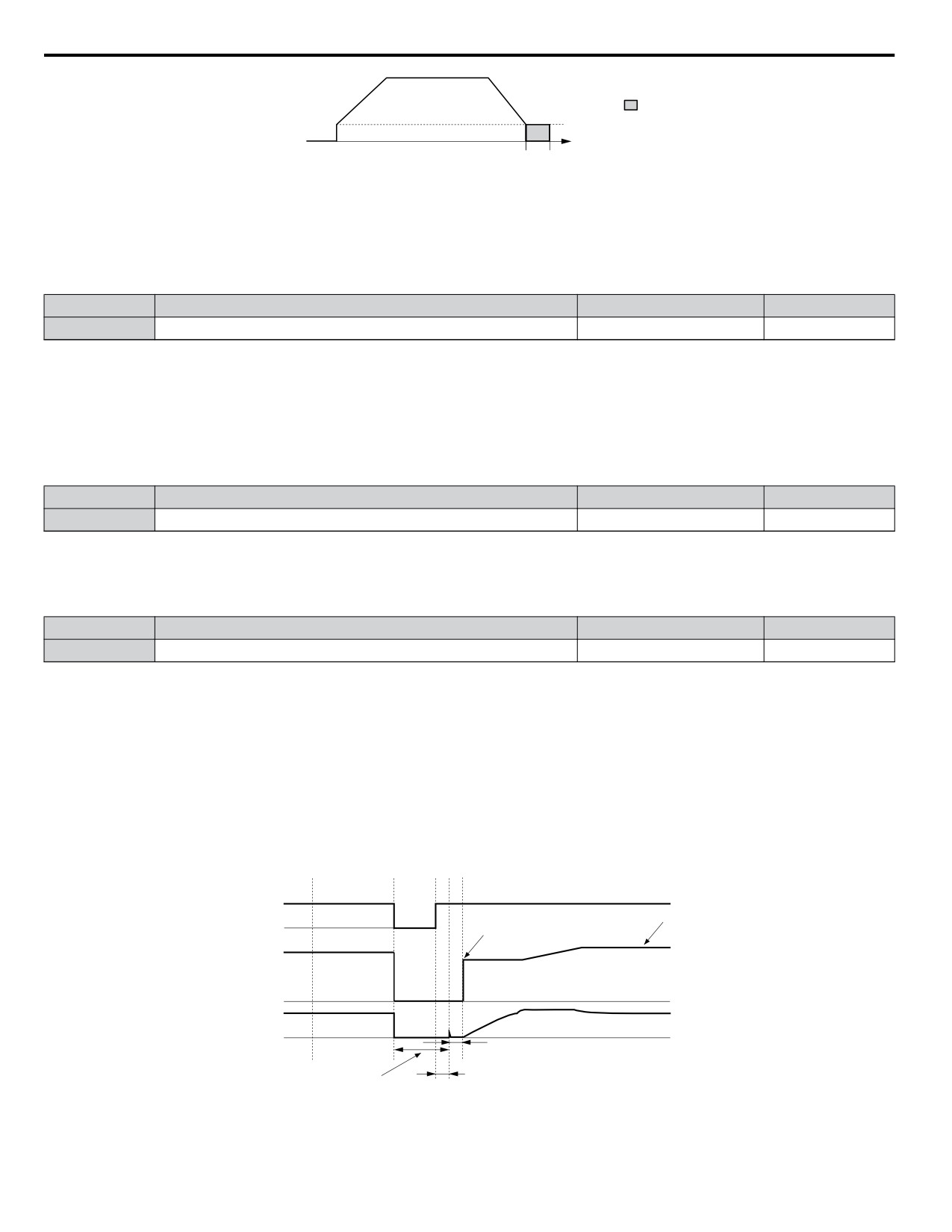
DC Injection Braking
start frequency
b2-01
output
braking time
frequency
b2-04
Figure 5.12 DC Injection Braking during Deceleration
n b2-02: DC Injection Braking Current
Sets the DC Injection Braking current as a percentage of the drive rated current. If set to larger than 50%, the carrier frequency
is automatically reduced to 1 kHz.
No.
Name
Setting Range
Default
b2-02
DC Injection Braking Current
0 to 75%
50%
The level of DC Injection Braking current affects the strength of the magnetic field attempting to lock the motor shaft.
Increasing the current level will increase the amount of heat generated by the motor windings. This parameter should only be
increased to the level necessary to hold the motor shaft.
n b2-03: DC Injection Braking Time at Start
Sets the time of DC Injection Braking at start. It can be used to stop a coasting motor before restarting it or to apply a braking
torque at start. Disabled when set to 0.00 s.
No.
Name
Setting Range
Default
b2-03
DC Injection Braking Time at Start
0.00 to 10.00 s
0.50 s
n b2-04: DC Injection Braking Time at Stop
This parameter works in combination with b2-01, and sets the DC Injection Braking time at stop. Used to completely stop a
motor with high inertia load after ramp down. Increase the setting if the motor tends to coast by inertia after a stop.
No.
Name
Setting Range
Default
b2-04
DC Injection Braking Time at Stop
0.00 to 10.00 s
0.50 s
n Speed Estimation Type Speed Search (b3-24 = 1)
This method can be used for a single motor connected to a drive. It should not be utilized if the motor is one or more frame
sizes smaller than the drive, at motor speeds above 130 Hz, or when using a single drive to operate more than one motor.
The Speed Estimation type distinguishes two kinds of operation, Back EMF voltage estimation and DC current injection.
Back EMF Voltage Estimation
This method is used by Speed Search after short Baseblock (e.g. a power loss where the drives CPU kept running and the Run
command was kept active). Here the drive estimates the motor speed by analyzing the back EMF voltage. It outputs the
estimated frequency and increases the voltage using the time constant set in parameter L2-04. After that the motor is accelerated
or decelerated to the frequency reference starting from the detected speed.
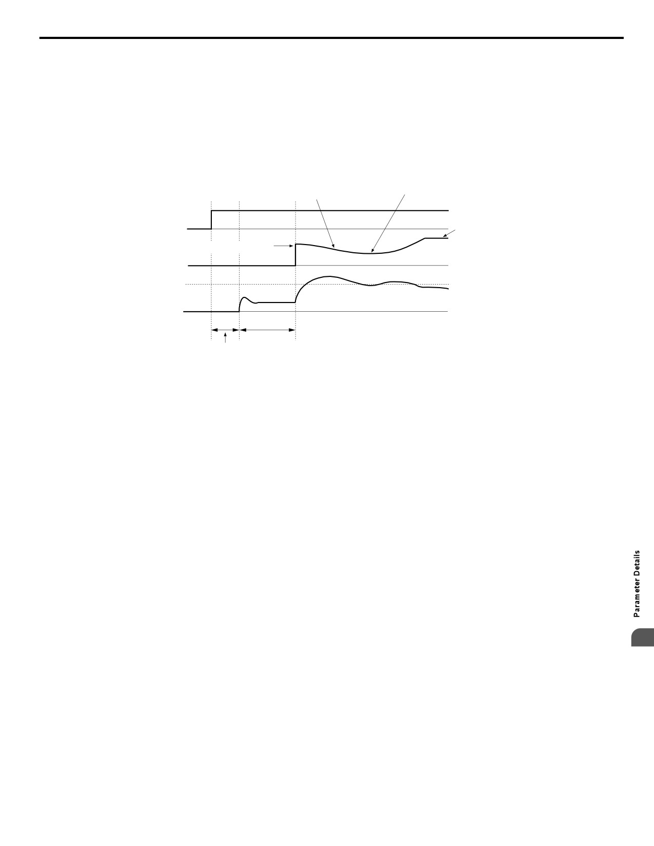
AC power
supply
ON
OFF
Selected
frequency
Starts at the detected speed
reference
Output
frequency
Output
current
Several milliseconds
Min. Baseblock Time
b3 -05
<1>
(L2-03)
Figure 5.13 Speed Search after Baseblock
124
5.2 b: Application
<1> Once AC power is restored, the drive will wait for at least the time set to b3-05. If the power interruption is longer than
the Minimum Baseblock Time L2-03, the drive will wait for b3-05 after the power has returned before starting Speed Search.
Current Injection
This method is used when there is no detectable back EMF, e.g. after longer power losses, when Speed Search is applied with
the Run command (b3-01 = 1) or if an External Search command is used. It injects the DC current set in b3-06 to the motor
and detects the speed by measuring the current feedback. The drive outputs the detected frequency and increases the voltage
using the time constant set in parameter L2-04. If the resulting current is higher than the level in b3-02 the output frequency
is reduced. When the current becomes lower than b3-02 the motor speed is assumed to be found and the drive starts to accelerate
or decelerate to the frequency reference.
Decelerates at the Speed
Waits for L2-04 x 2 time
Search decel time set to b3-03
ON
Run
OFF
Frequency reference
command
set to the drive
Starts at the detected speed
Output
frequency
b3-02
Output
current
1.0 s
Min. Baseblock Time (L2-03) <1>
Figure 5.14 Speed Search at Start
<1> The wait time for Speed Search (b3-05) determines the lower limit.
Note:
If the Run command is quickly switched off and then back on again when the drive is set to “Coast to stop” as the stopping method, Speed
Search will operate as shown in Figure 5.13.
Notes on Using Speed Estimation Type Speed Search
• Auto-Tuning needs to be first performed if you plan to use Speed Estimation. Perform Auto-Tuning again if the there is a
change in the cable length between the drive and motor.
• Use Current Detection to search for speeds beyond 130 Hz or if the application is running multiple motors from the same
drive, or if the motor is considerably smaller than the capacity of the drive.
• Speed Estimation may have trouble finding the actual speed if the motor cable very long. Current Detection should be used
in such situations.
• Use Current Detection instead of Speed Estimation when operating motors smaller than 1.5 kW. Speed Estimation can end
up stopping smaller motors as it might not be able to detect the speed or rotation direction of such small motors.
n Current Detection Type Speed Search (b3-24 = 0)
Current Detection Speed Search can be applied to any motor. Be aware that sudden acceleration may occur when using Current
Detection with relatively light loads.
This method detects the motor speed by reducing the output frequency and measuring the current. The frequency reduction
starts from the maximum output frequency or from the set frequency reference. As long as the output frequency is higher than
the rotor speed, the slip will cause a high current. The closer the output frequency comes to the rotor speed, the lower the
5
current draw will be. When the output current drops below the level as set in b3-02, the output frequency stops decreasing and
normal operation resumes.
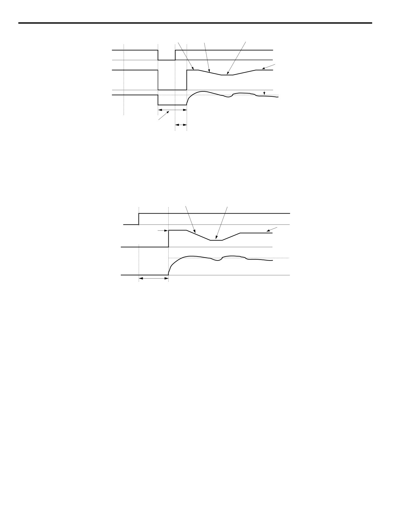
The following time chart illustrates how Current Detection Speed Search operates after a momentary power loss:
125
5.2 b: Application
Output frequency before
Decel time
Waits for L2-04 x 2 time
momentary power loss
set to b3-03
AC power
supply
ON
OFF
Selected
Output
frequency
reference
frequency
Speed Search operation
current set to b3-02
Output
current
Min. Baseblock Time (L2-03)
b3-05
Figure 5.15 Current Detection Speed Search after Power Loss
Note:
After power is restored, the drive waits until the time set to b3-05 has passed before performing Speed Search. Thereby the Speed Search
may start not at the end of L2-03 but even later.
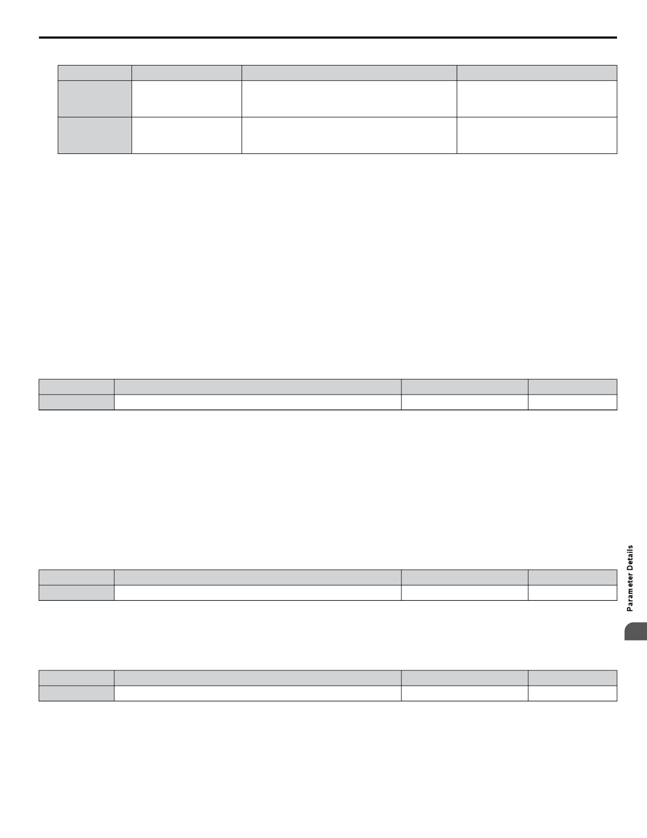
When Speed Search is applied using an external Search command or automatically with the Run command, the drive waits
for the minimum baseblock time L2-03 before Speed Search is started. If L2-03 is smaller than the time set in parameter b3-05,
b3-05 is used as the wait time.
Decel time
set to b3-03
Waits for L2-04 x 2 time
OFF
ON
Run command
Max. output frequency
Selected
or the specified
frequency
frequency reference
reference
Output
frequency
b3-02
Output current
Minimum Baseblock Time (L2-03)
Figure 5.16 Current Detection Speed Search at Start or External Speed Search
Note:
When the Run command is set the drive waits until the Speed Search Wait Time (b3-05) before Speed Search is performed, even if the
Minimum Baseblock Time is set to smaller values than b3-05.
Notes on Using Current Detection Type Speed Search
• Increase the voltage recovery ramp time set to L2-04 if a Uv1 fault occurs when performing Current Detection Speed Search.
• Shorten the Speed Search deceleration time set to b3-03 if an oL1 fault occurs while performing Current Detection Speed
Search.
• Increase the minimum baseblock time set to L2-03 if an overcurrent fault occurs when performing Speed Search after power
is restored following a momentary power loss.
n Activation of Speed Search
Speed Search can be activated as described below. Independent of the activation method the Speed Search type must be selected
in parameter b3-24.
1. Automatically at every Run command (Refer to b3-01: Speed Search Selection at Start on page 127). With this setting
external Speed Search commands are disregarded.
2. By digital inputs:
The following input functions for H1-oo can be used.
126
5.2 b: Application
Table 5.5 Speed Search Activation by Digital Inputs
Setting
Description
b3-24 = 0
b3-24 = 1
Closed: Activate Current Detection Speed
External Search
Activate Speed Estimation
61
Search from the maximum output frequency
Command 1
Speed Search
(E1-04).
Closed: Activate Current Detection Speed
External Search
62
Search from the frequency reference if b3-01
-
Command 2
is set to 0.
To activate Speed Search by a digital input the input must always be set together with the Run command.
3.
After automatic fault restart
Set the number of maximum fault restarts in parameter L5-01 higher than 0.
4.
After momentary power loss
The following parameter settings are necessary:
Enable Power Loss Ride-Thru selection by setting L2-01 to 1 (enabled) or 2 (enabled during CPU operation). Refer to
L2-01: Momentary Power Loss Operation Selection on page 193.
Se
•
t the number of maximum fault restarts in parameter L5-01 higher than 0.
5.
After baseblock is released
The drive will resume the operation starting with Speed Search if the Run command is present and the output frequency
is above the minimum frequency when the Baseblock command (H1-oo = 8 or 9, N.O. and N.C., respectively) is released.
n
b3-01: Speed Search Selection at Start
Determines if Speed Search is automatically performed when a Run command is issued.
No.
Parameter Name
Setting Range
Default
b3-01
Speed Search Selection at Start
0, 1
0
Setting 0: Disabled
This setting starts operating the drive at the minimum output frequency when the Run command is entered. If external Speed
Search 1 or 2 is already enabled by a digital input, the drive will start operating with Speed Search.
Setting 1: Enabled
This setting performs Speed Search when the Run command is entered. The drive begins running the motor after Speed Search
is complete.
n b3-02: Speed Search Deactivation Current
Sets Speed Search operating current as a percentage of the drive rated current. If the current falls below this level while
performing Current Detection Speed Search then Speed Search will be finished and normal operation will resume. Normally
there is no need to change this setting. If the drive won’t run after a restart, lower this value.
No.
Name
Setting Range
Default
b3-02
Speed Search Deactivation Current
0 to 200%
120%
n b3-03: Speed Search Deceleration Time
Parameter b3-03 sets the output frequency reduction ramp used by Current Detection Speed Search (b3-24 = 0) and by the
5
Current Injection Method of Speed Estimation (b3-24 = 1). The time entered into b3-03 will be the time to decelerate from
maximum frequency (E1-04) to minimum frequency (E1-09).
No.
Name
Setting Range
Default
b3-03
Speed Search Deceleration Time
0.1 to 10.0 s
2.0 s
n b3-05: Speed Search Delay Time
In cases where an output contactor is used between the drive and the motor, the contactor must be closed before Speed Search
can be performed. For Speed Search after a momentary power loss, parameter b3-05 can be used to delay the Speed Search
start providing enough time to operate the contactor.
When Speed Search at start is used, b3-05 will serve as the lower limit of the minimum baseblock time (L2-03).
127
5.2 b: Application
No.
Name
Setting Range
Default
b3-05
Speed Search Delay Time
0.0 to 100.0 s
0.2 s
n b3-06: Output Current 1 During Speed Search
Sets the current injected to the motor at the beginning of Estimation Type Speed Search as a factor related to motor rated
current set in E2-01 and E4-01. If the motor speed is relatively slow when the drive starts to perform Speed Search after a long
period of baseblock, it may be helpful to increase the setting value. The output current during Speed Search is automatically
limited by the drive rated current. This function has no influence when Current Detection Speed Search is used (b3-24 = 0).
No.
Name
Setting Range
Default
Determined by
b3-06
Output Current 1 during Speed Search
0.0 to 2.0
o2-04
Note:
If Speed Estimation is not working correctly even after adjusting b3-06, try using Current Detection Speed Search instead.
n b3-08: Current Control Gain during Speed Search (Speed Estimation Type)
Sets the proportional gain for the current controller during Speed Search. There is normally no need to change this parameter
from the default value.
No.
Name
Setting Range
Default
Current Control Gain during Speed Search
b3-08
0.00 to 6.00
0.50
(Speed Estimation Type)
n b3-10: Speed Search Detection Compensation Gain
This parameter sets the gain for the detected motor speed of the Speed Estimation Speed Search. The drive will start the motor
at the estimated speed multiplied by b3-10. The setting should be increased if an overvoltage fault occurs when the drive
restarts the motor. This function has no influence when Current Detection Speed Search is used (b3-24 = 0).
No.
Name
Setting Range
Default
b3-10
Speed Search Detection Compensation Gain
1.00 to 1.20
1.10
Note:
Increase this value if overvoltage occurs when performing Speed Search at start after a relatively long period of baseblock.
n b3-14: Bi-Directional Speed Search Selection
Sets how the drive determines the motor rotation direction when performing Speed Estimation Speed Search. The setting has
no influence on Current Detection Speed Search (b3-24 = 0).
No.
Parameter Name
Setting Range
Default
b3-14
Bi-Directional Speed Search Selection
0 or 1
0
Setting 0: Disabled
The drive uses the frequency reference to determine the direction of motor rotation in order to restart the motor.
Setting 1: Enabled
The drive detects the motor rotation direction in order to restart the motor.
n b3-17: Speed Search Restart Current Level
If there is a fairly large difference between the estimated frequency and the actual motor speed when performing Speed
Estimation, a large current can flow. This parameter sets the current level at which Speed Estimation is restarted, thus avoiding
overcurrent and overvoltage problems. The parameter is set as a percentage of the drive rated current. This function has no
influence when Current Detection Speed Search is used (b3-24 = 0).
No.
Name
Setting Range
Default
b3-17
Speed Search Restart Current Level
0 to 200%
150%
n b3-18: Speed Search Restart Detection Time
Sets the time the current must be above the level set in b3-17 before Speed Search is restarted. This function has no influence
when Current Detection Speed Search is used (b3-24 = 0)
No.
Name
Setting Range
Default
b3-18
Speed Search Restart Detection Time
0.00 to 1.00 s
0.10 s
128
5.2 b: Application
n b3-19: Number of Speed Search Restarts
Sets the number of times the drive should attempt to find the speed and restart the motor using Speed Estimation Speed Search.
This function has no influence when Current Detection Speed Search is used (b3-24 = 0).
No.
Name
Setting Range
Default
b3-19
Number of Speed Search Restarts
0 to 10
3
n b3-24: Speed Search Method Selection
Sets the Speed Search method used.
Note:
For explanations of the Speed Search methods, Refer to Current Detection Type Speed Search (b3-24 = 0) on page 125 and Refer to Speed
Estimation Type Speed Search (b3-24 = 1) on page 124.
No.
Parameter Name
Setting Range
Default
b3-24
Speed Search Method Selection
0 or 1
0
Setting 0: Current Detection Speed Search
Setting 1: Speed Estimation Speed Search
n b3-25: Speed Search Wait Time
Sets the wait time between Speed Search restarts.
No.
Name
Setting Range
Default
b3-25
Speed Search Wait Time
0.0 to 30.0 s
0.5 s
u b4: Delay Timers
The timer function is independent of the drive operation and can be used to delay the switching of a digital output triggered
by a digital input signal. An On-delay and Off-delay can be separately set. The delay timer can help to get rid of chattering
switch noise from sensors.
To enable the timer function, a multi-function input must be set to “Timer input” (H1-oo = 18) and a multi-function output
must be set to “Timer output” (H2-oo = 12). Only one timer can be used.
n b4-01/b4-02: Timer Function On/Off-Delay Time
b4-01 sets the On-delay time for switching the timer output. b4-02 sets the Off-delay time for switching the timer output.
No.
Name
Setting Range
Default
b4-01
Timer Function On-Delay Time
0.0 to 300.0 s
0.0 s
b4-02
Timer Function Off-Delay Time
0.0 to 300.0 s
0.0 s
n Timer Function Operation
When the timer function input closes for longer than the value set in b4-01, the timer output switches on. When the timer
function input is open for longer than the value set in b4-02, the timer output function switches off. The following diagram
demonstrates the timer function operation.
Multi-function Contact
On (Closed)
ON
ON
Input: Timer Function
Off (Open)
5
Multi-function Contact
ON
ON
On (Closed)
Output: Timer Function
Off (Open)
b4-01
b4-02
b4-01
b4-02
Figure 5.17 Timer Operation
u b5: PID Control
The drive has a built in PID (Proportional + Integral + Derivative) controller that can be used for closed loop control of system
variables such as pressure, temperature etc. The difference between the target and the feedback value (deviation) is fed into
the PID controller. The PID controller adjusts the drive output frequency in order to minimize the deviation, providing an
accurate control of the system variables.
129
5.2 b: Application
n P Control
The output of P control is the product of the deviation and the P gain so that it follows the deviation directly and linearly. With
P control only an offset between the target and feedback remains.
n I Control
The output of I control is the integral of the deviation. It minimizes the offset between target and feedback value that typically
remains when pure P control is used. The integral time (I-time) constant determines how fast the offset is eliminated.
n D Control
D control predicts the deviation signal by multiplying its derivative (slope of the deviation) with a time constant and adding
this to the PID input. This way the D portion of a PID controller provides a braking action to the controller response and can
reduce the tendency of oscillations and overshoot.
Be aware that D control tends to amplify noise on the deviation signal, which can result in control instability. D control should
therefore only be used when necessary.
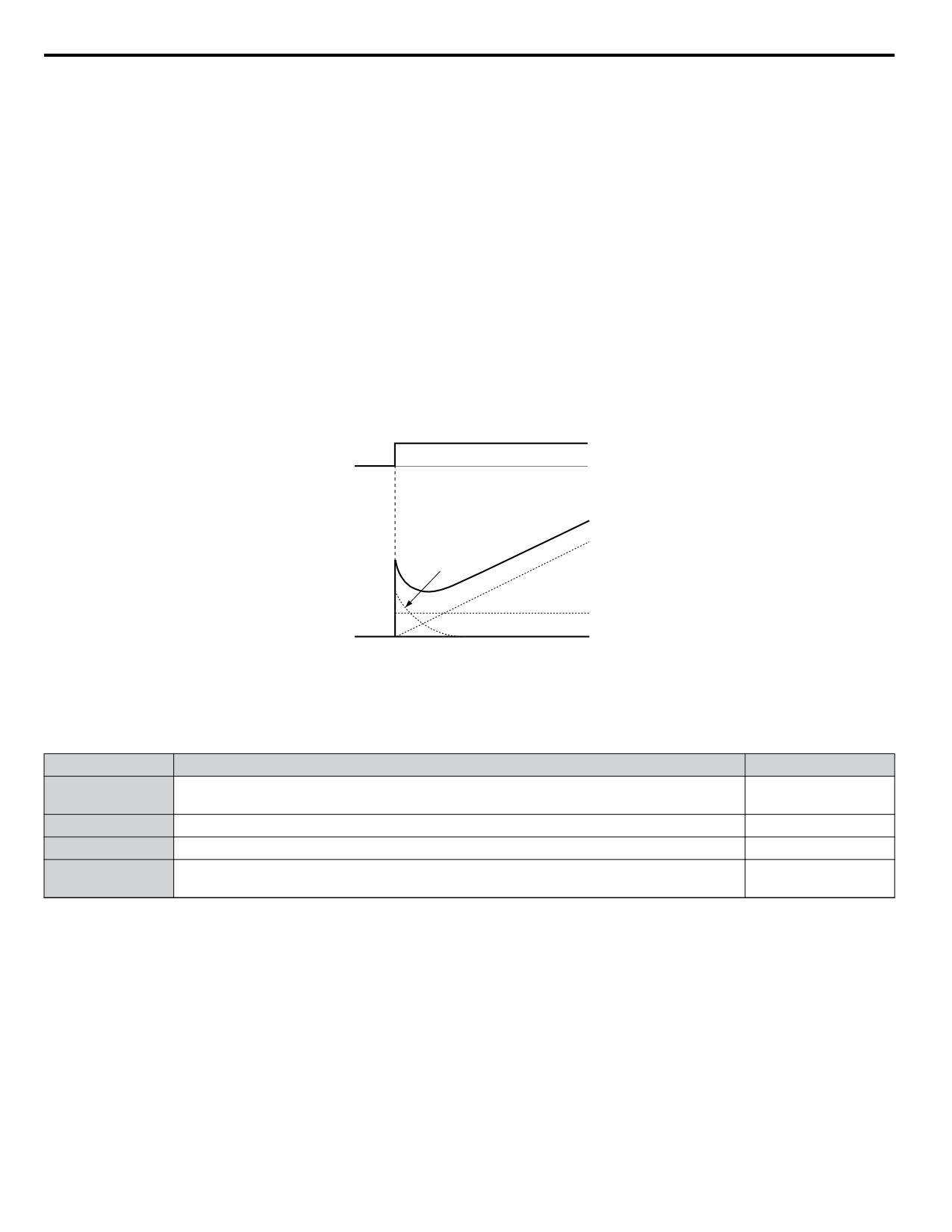
n PID Operation
To better demonstrate how PID works, the diagram below shows how the PID output changes when the PID input (deviation)
jumps from 0 to a constant level.
PID input
Time
PID output
I control
PID Output
D control
P control
Time
Figure 5.18 PID Operation
n Using PID Control
Applications for PID control are listed in the table below.
Application
Description
Sensors Used
Machinery speed is fed back and adjusted to meet the target value. Synchronous control is
Speed Control
Tachometer
performed using speed data from other machinery as the target value
Pressure
Maintains constant pressure using pressure feedback.
Pressure sensor
Fluid Control
Keeps flow at a constant level by feeding back flow data.
Flow rate sensor
Temperature
Thermocoupler,
Maintains a constant temperature by controlling a fan with a thermostat.
Control
Thermistor
130
5.2 b: Application
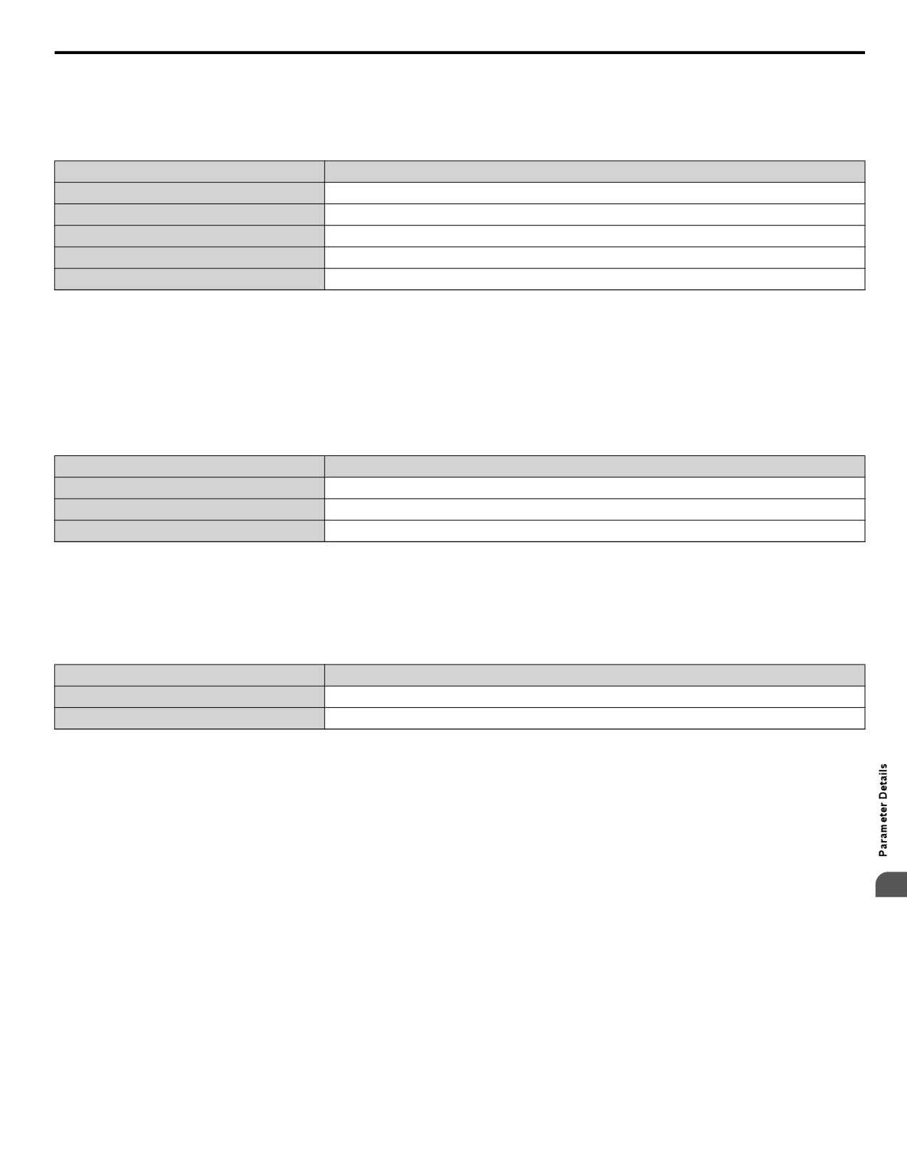
n PID Setpoint Input Methods
When the PID control parameter b5-01 is set to 1 or 2, the frequency reference in b1-01 (or b1-15) becomes the PID setpoint.
If b5-01 is set to 3 or 4, then the PID setpoint can be input from one of the sources in the following table.
Table 5.6 PID Setpoint Sources
PID Setpoint Source
Settings
Analog Input A1
Set H3-02 = C
Analog Input A2
Set H3-10 = C
MEMOBUS/Modbus Register 0006H
Set Bit 1 in register 000FH to 1 and input the setpoint to register 0006H
Pulse Input RP
Set H6-01 = 2
Parameter b5-19
Set parameter b5-18 = 1 and input the PID setpoint to b5-19
Note:
A duplicate allocation of the PID setpoint input will result in an OPE alarm.
n PID Feedback Input Methods
Either one feedback signal can be input for normal PID control or two feedback signals can be input for controlling a differential
process value.
Normal PID Feedback
The PID feedback can be input from one of the sources listed below.
Table 5.7 PID Feedback Sources
PID Feedback Source
Settings
Analog Input A1
Set H3-02 = B
Analog Input A2
Set H3-10 = B
Pulse Input RP
Set H6-01 = 1
Note:
A duplicate allocation of the PID feedback input will result in an OPE alarm.
Differential Feedback
The second PID feedback signal for differential feedback can come from the sources listed below. The differential feedback
function is automatically enabled when a differential feedback input is assigned.
Table 5.8 PID Differential Feedback Sources
PID Differential Feedback Source
Settings
Analog Input A1
Set H3-02 = 16
Analog Input A2
Set H3-10 = 16
Note:
A duplicate allocation of the PID differential feedback input will result in an oPE alarm.
5
131
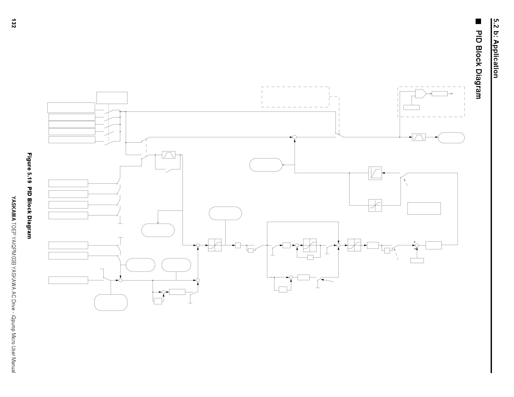
PID Block Diagram
PID disable when:
RUN
+
On/Off
Frequency
- b5-01=0
-
b5-16
Reference 1
- a JOG Command is Input
Delay
b1-01
- PID Disable by Digital Input Enabled
Timer
Frequency Reference 1 to 16
0
b5-15
d1-01 to d1-16
Sleep Level
1
Analog Input A1/A2
2
Sleep Function
Serial Comm
3
Disabled
Option Card
1/2
+
Output
4
0
Pulse Input
+
Enabled
Frequency
PID Soft
SFS
3/4
b5-01
Starter b5-17
C1-oo
1/2
3/4
Upper Limit
PID Ouput
Fmax x109%
On
(U5-03)
PID Target
0
Off
b5-11
Reg. 0Fh, bit 1
PID SFS Cancel DI
1
MEMOBUS Reg. 0006h
Lower Limit 0
1
0
H1-oo=34
Enable / Disable Reverse
b5-18=1
Upper Limit
b5-19
not 1
Operation when PID
Fmax x109%
Output is Negative
H6-01=2
Pulse Input
not 2
Always 1 when
PID Input
b5-01 = 3/4
H3-02/10=C
Analog Input A1/A2
not C
(U5-02)
Lower Limit
Fmax x109%
0
PID Set Point
Proportional
(U5-04)
I - limit
PID Feedback
Gain
PID Delay
0
I-time
b5-04
b5-02
Time
+
b5-03
+
0
0
+
0
+
0
Pulse Input
not 1
P
1/s
b5-08
b5-10
H6-01=1
-
+
+
-1
1
1
-1
1
1
PID Output
Analog Input A1/A2
not B
PID Input
PID Output
H3-02/10=B
Limit
PID Input
Integral Hold
Z-1
Gain
Adjusted
Upper/Lower
b5-07
PID Feedback
b5-35
Characteristic
Integral Reset
PID Output
PID Feedback
H1-oo=31
Limit
(U5-01)
H1-oo=35
H1-oo=30
b5-06 / b5-34
Characteristic
PID Offset
0
(U5-06)
b5-09
not 16
+
1 or 3
-
+
b5-05
+
+
Analog Input A1/A2
H3-02/10
Derivative
+
Derivative
b5-01
2 or 4
= 16
+
Time
2 or 4
Time
b5-05
Z-1
+
PID Differential
1 or 3
b5-01
Feedback
Z-1
(U5-05)
5.2 b: Application
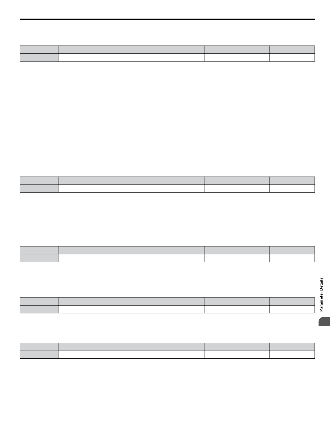
n b5-01: PID Function Setting
Enables or disables the PID operation and selects the PID operation mode.
No.
Parameter Name
Setting Range
Default
b5-01
PID Function Setting
0 to 4
0
Setting 0: PID disabled
Setting 1: Output Frequency = PID Output 1
The PID controller is enabled and the PID output builds the frequency reference. The PID input is D controlled.
Setting 2: Output Frequency = PID Output 2
The PID controller is enabled and the PID output builds the frequency reference. The PID feedback is D controlled.
Setting 3: Output Frequency = Frequency Reference + PID Output 1
The PID controller is enabled and the PID output is added to the frequency reference. D control is applied to the difference of
the feedback value (U5-02) and the setpoint.
Setting 4: Output Frequency = Frequency Reference + PID Output 2
The PID controller is enabled and the PID output is added to the frequency reference. Applies D control on the feedback value
(U5-06).
n b5-01: PID Function Setting
Enables and disables the PID operation and selects the PID operation mode.
No.
Parameter Name
Setting Range
Default
b5-01
PID Function Setting
0, 1
1
Setting 0: PID disabled
Setting 1: Output frequency = PID output 1
The PID controller is enabled and the PID output builds the frequency reference. The PID input is D controlled.
n b5-02: Proportional Gain Setting (P)
Sets the P gain that is applied to the PID input. A large value will tend to reduce the error, but may cause instability (oscillations)
if too high. A small value may allow too much offset between the setpoint and feedback.
No.
Name
Setting Range
Default
b5-02
Proportional Gain Setting (P)
0.00 to 25.00
2.00
n b5-03: Integral Time Setting (I)
Sets the time constant used to calculate the integral of the PID input. The shorter the integral time set to b5-03, the faster the
offset will be eliminated. If the integral time is set too short, however, overshoot or oscillation may occur. To turn off the
integral time, set b5-03 to 0.00.
No.
Name
Setting Range
Default
b5-03
Integral Time Setting (I)
0.0 to 360.0 s
3.0 s
n b5-09: PID Output Level Selection
5
Reverses the sign of the PID controller output signal. Normally a positive PID input (feedback smaller than setpoint) leads to
positive PID output.
No.
Parameter Name
Setting Range
Default
b5-09
PID Output Level Selection
0, 1
0
Setting 0: Direct Acting
A positive PID input causes an increase in the PID output (direct acting).
Setting 1: Inverse Acting
A positive PID input causes a decrease in the PID output (reverse acting).
133
5.2 b: Application
n b5-04: Integral Limit Setting
Sets the maximum output possible from the integral block. Set as a percentage of the maximum frequency (E1-04).
No.
Name
Setting Range
Default
b5-04
Integral Limit Setting
0.0 to 100.0
100.0
Note:
On some applications, especially those with rapidly varying loads, the output of the PID function may show a fair amount of oscillation.
To suppress this oscillation, a limit can be applied to the integral output by programming b5-04.
n b5-05: Derivative Time (D)
Sets the time the drive predicts the PID input/PID feedback signal based on the derivative of the PID input/PID feedback.
Longer time settings will improve the response but can cause vibrations. Shorter settings will reduce the overshoot but also
reduce the controller responsiveness. D control is disabled by setting b5-05 to zero seconds.
No.
Name
Setting Range
Default
b5-05
Derivative Time
0.00 to 10.00 s
0.00 s
n b5-06: PID Output Limit
Sets the maximum output possible from the entire PID controller. Set as a percentage of the maximum frequency (E1-04).
No.
Name
Setting Range
Default
b5-06
PID Output Limit
0.0 to 100.0%
100.0%
n b5-07: PID Offset Adjustment
Sets the offset added to the PID controller output. Set as a percentage of the maximum frequency.
No.
Name
Setting Range
Default
b5-07
PID Offset Adjustment
-100.0 to 100.0%
0.0%
n b5-08: PID Primary Delay Time Constant
Sets the time constant for the filter applied to the output of the PID controller. Normally, change is not required.
No.
Name
Setting Range
Default
b5-08
PID Primary Delay Time Constant
0.00 to 10.00 s
0.00 s
Note:
Effective in preventing oscillation when there is a fair amount of oscillation or when rigidity is low. Set to a value larger than the cycle of
the resonant frequency. Increasing this time constant reduces the responsiveness of the drive.
n b5-09: PID Output Level Selection
Normally, the output of the PID function increase whenever the PID input is negative (feedback below setpoint). Using b5-09
the PID controller can be set up for applications that require opposite operation.
No.
Parameter Name
Setting Range
Default
b5-09
PID Output Level Selection
0 or 1
0
Setting 0: Normal Output
A negative PID input causes an increase in the PID output (direct acting).
Setting 1: Reverse Output
A negative PID input causes a decrease in the PID output (reverse acting).
n b5-10: PID Output Gain Setting
Applies a gain to the PID output and can be helpful when the PID function is used to trim the frequency reference (b5-01 = 3
or 4). Increasing b5-10 causes the PID function to have a greater regulating effect on the frequency reference.
No.
Name
Setting Range
Default
b5-10
PID Output Gain Setting
0.00 to 25.00
1.00
n b5-11: PID Output Reverse Selection
Determines whether a negative PID output reverses the drive operation direction or not. When the PID function is used to trim
the frequency reference (b5-01 = 3 or 4), this parameter has no effect and the PID output will not be limited (same as
134
5.2 b: Application
b5-11 = 1).
No.
Parameter Name
Setting Range
Default
b5-11
PID Output Reverse Selection
0 or 1
0
Setting 0: Reverse Disabled
Negative PID output will be limited to 0 and the drive output will be stopped.
Setting 1: Reverse Enabled
Negative PID output will cause the drive to run in the opposite direction.
n PID Feedback Loss Detection
The PID Feedback Loss Detection function can detect broken sensors or broken sensor wiring. It should be used whenever
PID control is enabled to prevent critical machine conditions (e.g. acceleration to max. frequency) caused by a feedback loss.
Feedback loss can be detected in two ways:
• Feedback Low Detection:
Detected when the feedback falls below a certain level for longer than the specified time.
• Feedback High Detection:
Detected when the feedback rises beyond a certain level for longer than the specified time.
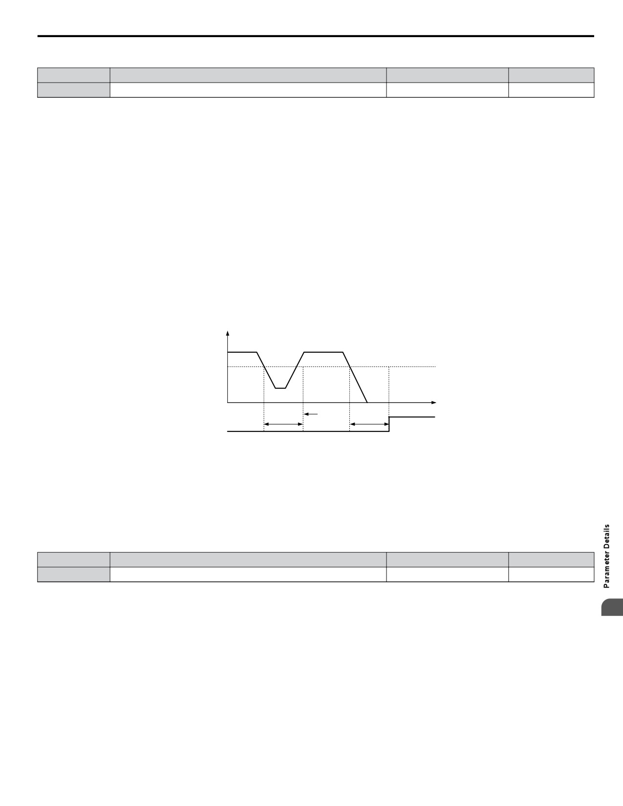
The following figure explains the working principle of feedback loss detection when the feedback signal is too low. Feedback
high detection works in the same way.
PID feedback value
PID
Feedback
Detection
Loss Level
(b5-13)
time
no FbL
detection
FbL detection
PID Feedback
PID Feedback
Loss Detection Time
Loss Detection Time
(b5-14)
(b5-14)
Figure 5.20 PID Feedback Loss Detection
The parameters necessary to set up the feedback loss detection are explained below.
n b5-12: PID Feedback Loss Detection Selection
Enables or disables the feedback loss detection and sets the operation when a feedback loss is detected.
No.
Parameter Name
Setting Range
Default
b5-12
PID Feedback Loss Detection Selection
0 to 5
0
Setting 0: Digital Output Only
A digital output set for “PID feedback low” (H2-oo = 3E) will be triggered if the PID feedback value is below the detection
5
level set to b5-13 for the time set to b5-14 or longer. A digital output set for “PID feedback high” (H2-oo = 3F) will be
triggered if the PID feedback value is beyond the detection level set to b5-36 for the time set to b5-37 or longer. Neither a
fault nor an alarm is displayed on the digital operator. The drive will continue operation. When the feedback value leaves the
loss detection range, the output is reset.
Setting 1: Feedback Loss Alarm
If the PID feedback value falls below the level set to b5-13 for longer than the time set to b5-14, a “FBL - Feedback Low”
alarm will be displayed and a digital output set for “PID feedback low” (H2-oo = 3E) will be triggered. If the PID feedback
value exceeds the level set to b5-36 for longer than the time set to b5-37, a “FBH - Feedback High” alarm will be displayed
and a digital output set for “PID feedback high” (H2-oo = 3F) will be triggered. Both events trigger an alarm output (H1-
oo = 10). The drive will continue operation. When the feedback value leaves the loss detection range, the alarm and outputs
are reset.
135
5.2 b: Application
Setting 2: Feedback Loss Fault
If the PID feedback value falls below the level set to b5-13 for longer than the time set to b5-14, a “FBL - Feedback Low”
fault will be displayed. If the PID feedback value exceeds the level set to b5-36 for longer than the time set to b5-37, a “FBH
- Feedback High” fault will be displayed. Both events trigger a fault output (H1-oo = E) and cause the drive to stop the
motor.
Setting 3: Digital Output Only, Even if PID is Disabled by Digital Input
Same as b5-12 = 0. Detection is still active even if PID is disabled by a digital input (H1-oo = 19).
Setting 4: Feedback Loss Alarm, Even if PID is Disabled by Digital Input
Same as b5-12 = 1. Detection is still active even if PID is disabled by a digital input (H1-oo = 19).
Setting 5: Feedback Loss Fault, Even if PID is Disabled by Digital Input
Same as b5-12 = 2. Detection is still active even if PID is disabled by a digital input (H1-oo = 19).
n b5-13: PID Feedback Loss Detection Level
Sets the feedback level used for PID feedback loss detection. The PID feedback has to fall below this level for longer than the
time b5-14 before feedback loss is detected.
No.
Name
Setting Range
Default
b5-13
PID Feedback Loss Detection Level
0 to 100%
0%
n b5-14: PID Feedback Loss Detection Time
Sets the time that the PID feedback has to fall below b5-13 before feedback loss is detected.
No.
Name
Setting Range
Default
b5-14
PID Feedback Loss Detection Time
0.0 to 25.5 s
1.0 s
n PID Sleep
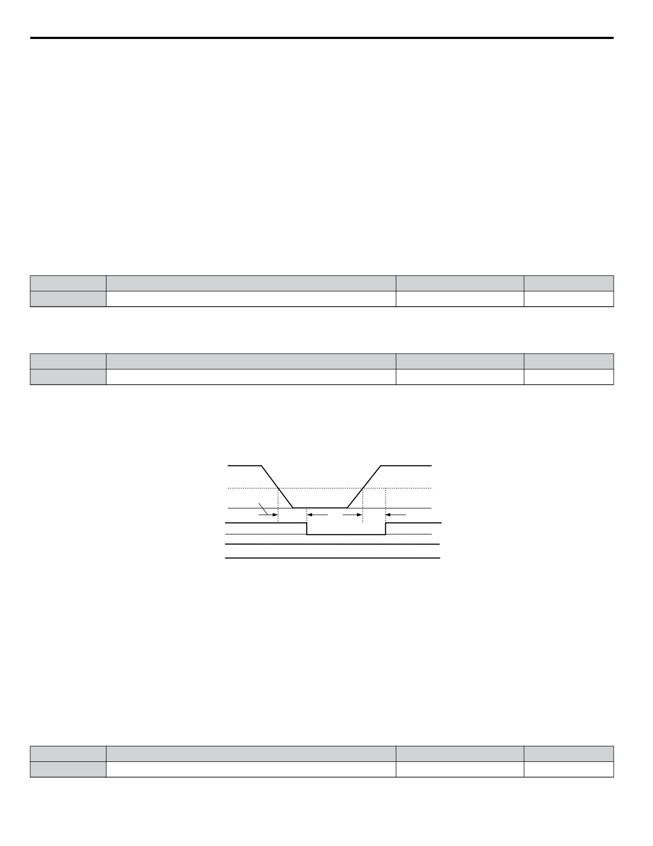
The PID Sleep function stops the drive when the PID output or the frequency reference falls below the PID Sleep operation
level for a certain time. The drive will resume operating once the PID output or frequency reference rises above the PID Sleep
operation level for the specified time. The operation is explained in the figure below.
PID Output
PID Sleep Function
Start Level ( b5-15)
Sleep Delay Time
b5-16
b5-16
Sleep Delay Time
Internal Run
command
Run
Stop
External Run
Run command enabled
command
Continues to output “During Run”
During Run
Figure 5.21 PID Sleep Operation
Notes on using the PID Sleep function:
• The PID Sleep function is always active, even if PID control is disabled.
• The method the Sleep function uses to stop the motor is defined by parameter b1-03.
• The parameters necessary to set up the PID Sleep function are explained below.
n b5-15: PID Sleep Function Start Level
Sets the level used for PID Sleep.
The drive goes into Sleep mode if the PID output or frequency reference is smaller than b5-15 for longer than the time set in
b5-16. It resumes the operation when the PID output or frequency reference is above b5-15 for longer than the time set in
b5-16.
No.
Name
Setting Range
Default
b5-15
PID Sleep Function Start Level
0.0 to 400.0 Hz
0.0 Hz
136
5.2 b: Application
n b5-16: PID Sleep Delay Time
Sets the delay time to activate or deactivate the PID Sleep function.
No.
Name
Setting Range
Default
b5-16
PID Sleep Delay Time
0.0 to 25.5 s
0.0 s
n b5-17: PID Accel/Decel Time
The PID acceleration/deceleration time is applied on the PID setpoint value.
As the normal acceleration times C1-oo are applied after the PID output, they reduce the responsiveness of the system and
can cause hunting or over- and undershooting when the setpoint changes quickly. Using the PID acceleration/deceleration
time instead helps to avoid such problems.
The PID acceleration/deceleration time can be canceled using a digital input programmed for “PID SFS cancel” (H1-oo =
34).
No.
Name
Setting Range
Default
b5-17
PID Accel/Decel Time
0 to 255 s
0 s
n b5-32: Integrator Ramp Limit
The Integrator Ramp Limit provides a way to tune the PI loop so that it is less reactive to sudden spikes and dips in the feedback
signal. Pressure waves may develop in a pressure regulated systems with long piping and the Integrator Ramp Limit function
helps curb instability in the PI controller in such situations.
When the Integrator Ramp Limit is enabled, the PI Integrator is limited to +/- the b5-32 value of the soft starter output (output
frequency without slip compensation).
A b5-32 setting of zero disables this feature and the integrator is allowed to operate normally.
This feature only applies to the drive standard PI loop. It does not apply to the PI loop associated with the water level control
function (well draw-down control) (Q4 parameters).
No.
Name
Setting Range
Default
b5-32
Integrator Ramp Limit
0.0 to 10.0 Hz
0.0 Hz
n b5-34: PID Output Lower Limit
Sets the minimum possible PID controller output as a percentage of the maximum output frequency (E1-04). The lower limit
is disabled when set to 0.00%
No.
Name
Setting Range
Default
b5-34
PID Output Lower Limit
-100.0 to 100.0%
0.00%
n b5-35: PID Input Limit
Sets the maximum allowed PID input as a percentage of the maximum output frequency (E1-04). Parameter b5-35 acts as a
bipolar limit.
No.
Name
Setting Range
Default
b5-35
PID Input Limit
0.0 to 1000.0%
1000.0%
5
n b5-39: PID System Units Display Digits
Determines the number of digits for the user-defined display for the PID setpoint (Q1-oo) and PID feedback monitors (U5-01,
U5-04). The setting value is equal to the number of decimal places.
No.
Name
Setting Range
Default
b5-39
PID System Units Display Digits
0 to 3
1
137
5.2 b: Application
Setting 0: No Decimal Places
Setting 1: One Decimal Place
Setting 2: Two Decimal Places
Setting 3: Three Decimal Places
n b5-40: Frequency Reference Monitor Content During PID
Sets the content on the frequency reference monitor display (U1-01) when PID control is active.
No.
Name
Setting Range
Default
b5-40
Frequency Reference Monitor Content During PID
0 or 1
0
Setting 0: Frequency Reference after PID
Monitor U1-01 displays the frequency reference increased or reduced for the PID output.
Setting 1: Frequency Reference
Monitor U1-01 displays the frequency reference value.
n b5-47: Reverse Operation Selection 2 by PID Output
Reverses operation selection when b5-01 is set to 3 or 4.
No.
Name
Setting Range
Default
b5-47
Reverse Operation Selection 2 by PID Output
0 or 1
1
Setting 0: Zero Limit when PID Output is a Negative Value
Setting 1: Reverse Operation when PID Output is a Negative Value (Zero Limit if the Reverse Operation Is Prohibited
by b1-04)
u b6: Dwell Function
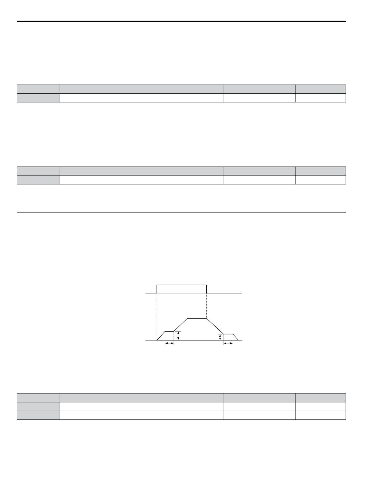
The reference hold or Dwell function is used to temporarily hold the output frequency at a set reference value, for a set time,
and then continue to ramp up or stop.
The Dwell at start function can be used when driving a permanent magnet motor in V/f Control, or a motor with a heavy
starting load. The pause in acceleration allows the PM motor rotor to align with the stator field of the motor, thus reducing the
starting current.
Dwell works as shown in the figure below.
Note:
Using the Dwell function requires that the stopping method for the drive be set to “Ramp to Stop” (b1-03 = 0).
OFF
ON
OFF
Run Command
b6-01
b6-03
Output Frequency
b6-02
b6-04
Figure 5.22 Dwell Function at Start and Stop
n b6-01/b6-02: Dwell Reference/Time at Start
b6-01 sets the frequency that is kept for the time set in b6-02 during acceleration.
No.
Name
Setting Range
Default
b6-01
Dwell Reference at Start
0.0 to 400.0 Hz
0.0 Hz
b6-02
Dwell Time at Start
0.0 to 10.0 s
0.0 s
138
5.2 b: Application
n b6-03/b6-04: Dwell Reference/Time at Stop
Parameter b6-03 sets the frequency that is kept for the time set in b6-04 during deceleration.
No.
Name
Setting Range
Default
b6-03
Dwell Reference at Stop
0.0 to 400.0 Hz
0.0 Hz
b6-04
Dwell Time at Stop
0.0 to 10.0 s
0.0 s
5
139
5.3 C: Tuning
5.3
C: Tuning
C parameters are used to set the acceleration and deceleration characteristics, as well as S-curves. Other parameters in this
group cover settings for slip compensation, torque compensation, and carrier frequency.
u C1: Acceleration and Deceleration Times
n C1-01 to C1-04: Accel, Decel Times 1 and 2
Two different sets of acceleration and deceleration times can be set in the drive by digital inputs, motor selection, or switched
automatically.
Acceleration time parameters always set the time to accelerate from 0 Hz to the maximum output frequency (E1-04).
Deceleration time parameters always set the time to decelerate from maximum output frequency to 0 Hz. C1-01 and C1-02
are the default active accel/decel settings.
No.
Parameter Name
Setting Range
Default
C1-01
Acceleration Time 1
20.0 s
C1-02
Deceleration Time 1
0.0 to 6000.0 s <1>
C1-03
Acceleration Time 2
10.0 s
C1-04
Deceleration Time 2
<1> The setting range for the acceleration and deceleration times is determined by the accel/decel time setting units in C1-10. For example, if the time
is set in units of 0.01 s (C1-10 = 0), the setting range becomes 0.00 to 600.00 s.
Switching Acceleration Times by Digital Input
Accel/decel time 1 is active by default if no input is set. Activate accel/decel times 2, 3, and 4 by digital inputs
(H1-oo = 7 and 1A) as explained in Table 5.9.
Table 5.9 Accel/Decel Time Selection by Digital Input
Accel/Decel Time Sel. 1
Accel/Decel Time Sel. 2
Active Times
H1-oo = 7
H1-oo = 1A
Acceleration
Deceleration
0
0
C1-01
C1-02
1
0
C1-03
C1-04
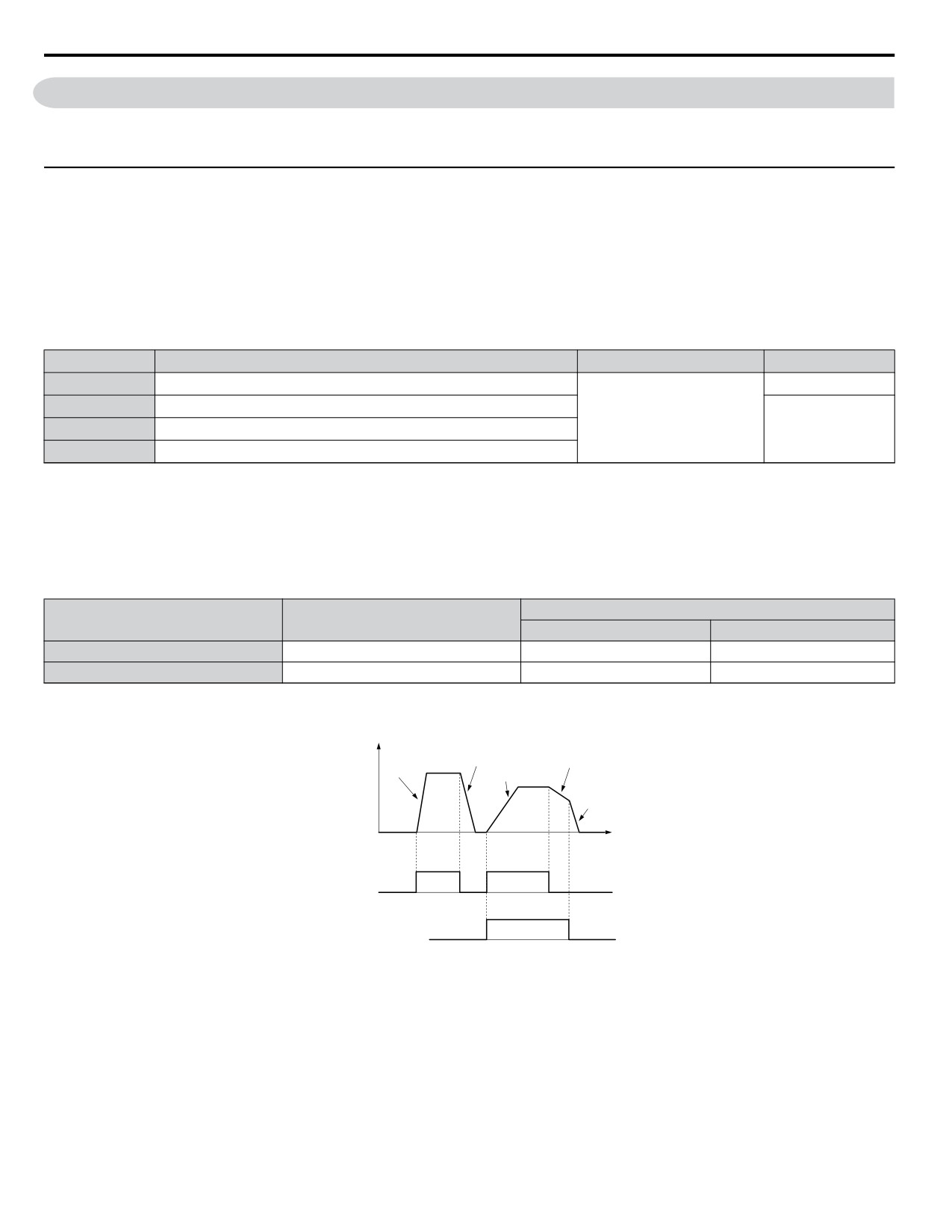
Figure 5.23 shows an operation example for changing accel/decel times. The example below requires that the stopping method
be set for “Ramp to stop” (b1-03 = 0).
Decel Time 1
Decel Time 2
(C1-02)
Accel Time 1
(C1-04)
Accel Time 2
Output
(C1-01)
(C1-03)
frequency
Decel Time 1
(C1-02)
Time
ON
OFF
ON
FWD (REV)
Run command
ON
OFF
Accel/Decel Time Selection 1
(Terminals S1 to S7, H1- oo = “7”)
Figure 5.23 Timing Diagram of Accel/Decel Time Change
n C1-09: Fast-stop Time
Parameter C1-09 will set a special deceleration that is used when certain faults occur or that can be operated by closing a
digital input configured as H1-oo = 15 (N.O. input) or H1-oo = 17 (N.C. input). The input does not have to be closed
continuously, even a momentary closure will trigger the Fast-stop operation.
Unlike standard deceleration, once the Fast-stop operation is initiated, the drive cannot be restarted until the deceleration is
complete, the Fast-stop input is cleared, and the Run command is cycled.
A digital output programmed for “During Fast-stop” (H2-01/02/03 = 4C) will be closed as long as Fast-stop is active.
140
5.3 C: Tuning
No.
Parameter Name
Setting Range
Default
C1-09
Fast-stop Time
0.0 to 6000.0 s <1>
10.0 s
<1> The setting range for the acceleration and deceleration times is determined by C1-10 (Accel/Decel Time Setting Units). For example, if the time is
set in units of 0.01 s (C1-10 = 0), the setting range becomes 0.00 to 600.00 s
NOTICE: Rapid deceleration can trigger an overvoltage fault. When faulted, the drive output shuts off, and the motor coasts. To avoid this
uncontrolled motor state and to ensure that the motor stops quickly and safely, set an appropriate Fast-stop time to C1-09.
n C1-10: Accel/Decel Time Setting Units
Determines the units for the acceleration and deceleration times set to C1-01 through C1-09 using parameter C1-10.
No.
Parameter Name
Setting Range
Default
C1-10
Accel/Decel Time Setting Units
0 or 1
1
Setting 0: 0.01 s Units
The accel/decel. times are set in 0.01 s units. The setting range will be 0.00 to 600.00 s. If any of the parameters C1-01 to
C1-09 is set to 600.1 seconds or more, then C1-10 cannot be set to 0.
Setting 1: 0.1 s Units
The accel/decel. times are set in 0.1 s units. The setting range will be 0.0 to 6000.0 s.
n C1-11: Accel/Decel Switch Frequency
Sets the switching frequency for automation accel/decel time change over.
No.
Parameter Name
Setting Range
Default
C1-11
Accel/Decel Switch Frequency
0.0 to 400.0 Hz
0.0 Hz
Note:
Setting C1-11 to 0.0 Hz disables this function.
n C1-14: Accel/Decel Rate Frequency
Sets the base frequency used to calculate acceleration and deceleration times.
No.
Parameter Name
Setting Range
Default
C1-14
Accel/Decel Rate Frequency
0.0 to 400.0 Hz
0.0 Hz
Note:
The accel/decel rates set to parameters C1-01 to C1-09 change in response to the value set to C1-14.
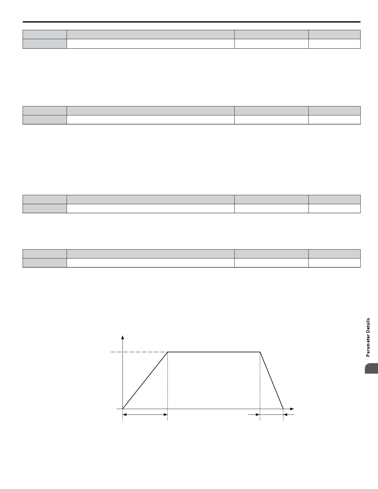
When C1-14 = 0.0 Hz
Operation example is shown in Figure 5.24.
• Accel Times 1 through 4 determine the time required to accelerate from 0 to the maximum output frequency (E1-04)
• Decel Times 1 through 4 and the Fast-stop Time determine the time required to decelerate from the Maximum Output
Frequency (E1-04) to 0 Hz.
Output
frequency
E1-04 = 60 Hz
Frequency
reference = 60 Hz
5
Time
0
Accel Times 1 to 4
Decel Times 1 to 4
Figure 5.24 Accel/Decel Rate, Example 1 (C1-14 = 0 Hz, E1-04 = 60 Hz, Frequency Reference = 60 Hz)
When C1-14
0.0 Hz
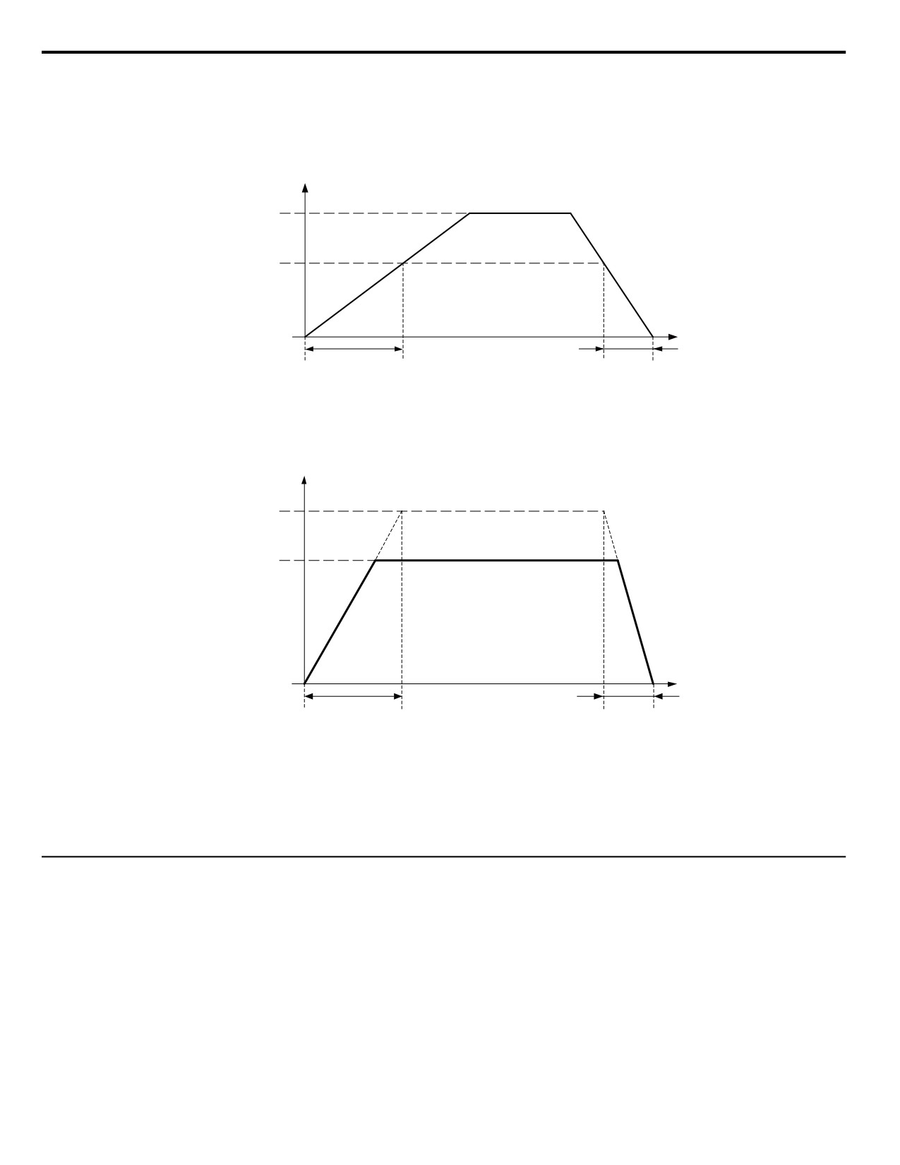
Operation examples are shown in Figure 5.25 and Figure 5.26.
141
5.3 C: Tuning
• Accel Times 1 through 4 determine the time required to accelerate from 0 to the value set in C1-14 (Accel/Decel Rate
Frequency)
• Decel Times 1 through 4 and the Fast-stop Time determine the time required to decelerate from the value set in C1-14 (Accel/
Decel Rate Frequency ) to 0 Hz.
Output
frequency
Frequency
reference = 60 Hz
C1-14 = 40 Hz
Time
0
Accel Times 1 to 4
Decel Times 1 to 4
Figure 5.25 Accel/Decel Rate, Example 2 (C1-14 = 40 Hz, E1-04 = 60 Hz, Frequency Reference = 60 Hz)
Output
frequency
C1-14 = 80 Hz
Frequency
reference = 60 Hz
Time
0
Decel Times 1 to 4
Accel Times 1 to 4
Figure 5.26 Accel/Decel Rate, Example 3 (C1-14 = 80 Hz, E1-04 = 60 Hz, Frequency Reference = 60 Hz)
Note:
1. The accel/decel times shown in Figure 5.24 to Figure 5.26 assume S-curve characteristic time during accel/decel at start and accel/
decel at stop of 0.00 s (parameters C2-01 to C2-04).
2. When Stall Prevention during acceleration is enabled (L3-01 ≠ 0), the accel time may take longer than the set value.
3. When Stall Prevention during deceleration is enabled (L3-04 ≠ 0), the decel time may take longer than the set value.
u C2: S-Curve Characteristics
Use S-curve characteristics to smooth acceleration and deceleration and to minimize abrupt shock to the load. Set S-curve
characteristic time during acceleration/deceleration at start and acceleration/deceleration at stop. If a STo fault (Step Out
Detection) occurs when starting a PM motor, try increasing the value set to C2-01.
142
5.3 C: Tuning
n C2-01 to C2-04: S-Curve Characteristics
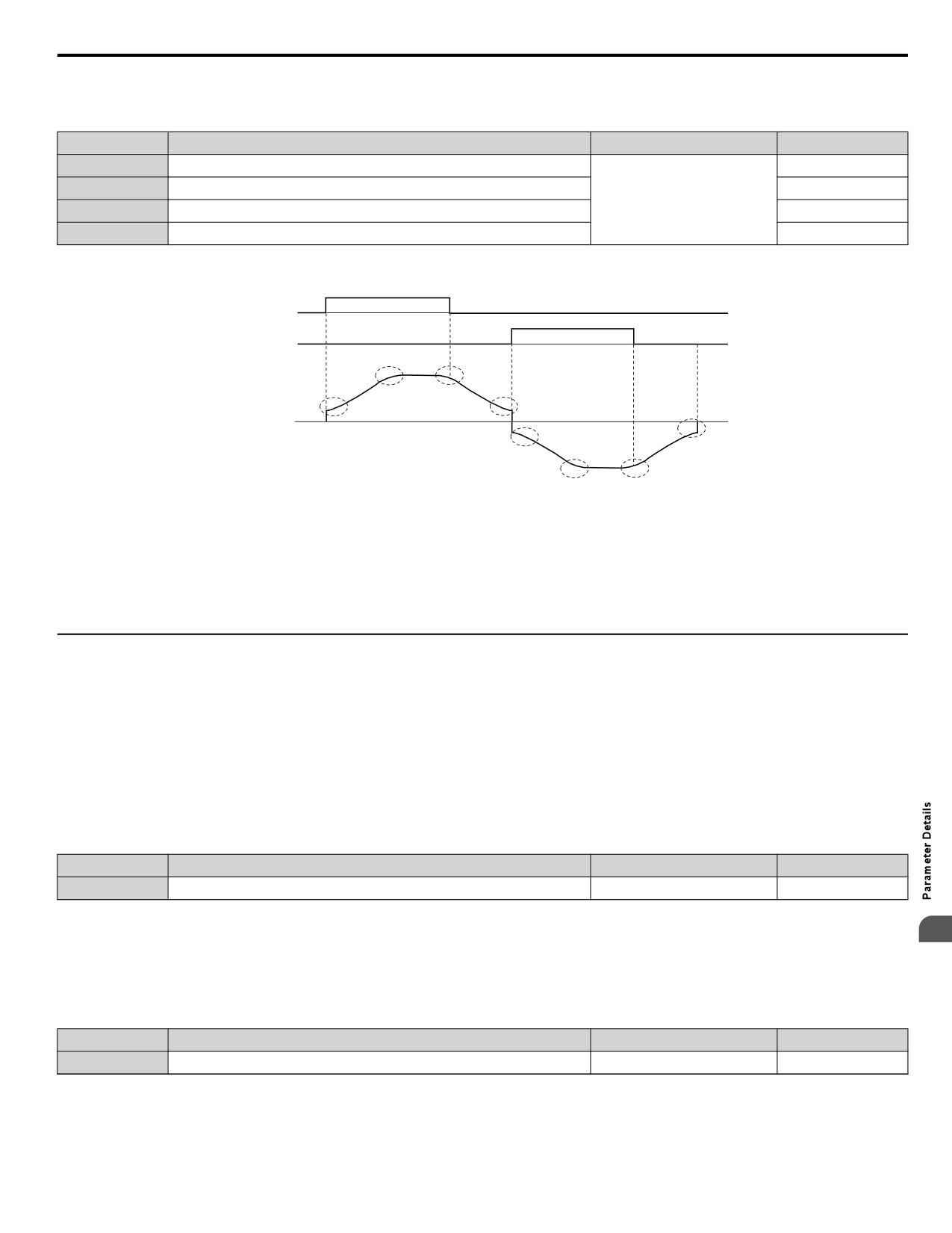
C2-01 through C2-04 set separate S-curves for each section of the acceleration or deceleration.
No.
Parameter Name
Setting Range
Default
C2-01
S-Curve Characteristic at Accel Start
0.20 s
C2-02
S-Curve Characteristic at Accel End
0.20 s
0.00 to 10.00 s
C2-03
S-Curve Characteristic at Decel Start
0.20 s
C2-04
S-Curve Characteristic at Decel End
0.00 s
Figure 5.27 explains how S-curves are applied.
FWD run
REV run
C2-04
C2-02
C2-03
Output
frequency C2-01
C2-04
C2-01
C2-02
C2-03
Figure 5.27 S-Curve Timing Diagram - FWD/REV Operation
Setting the S-curve will increase the acceleration and deceleration times.
Actual accel time = accel time setting + (C2-01 + C2-02)/2
Actual decel time = decel time setting + (C2-03 + C2-04)/2
u C3: Slip Compensation
The Slip Compensation function prevents motor speed loss due to an increase in load.
Note:
Before making changes to the Slip Compensation parameters, make sure the motor parameters and V/f pattern are set properly or perform
Auto-Tuning.
n C3-01: Slip Compensation Gain
This parameter sets the gain for the motor slip compensation function. Although this parameter rarely needs to be changed,
adjustments might be needed under the following situations:
• If the speed at constant frequency reference is lower than the frequency reference, increase C3-01.
• If the speed at constant frequency reference is higher than the frequency reference, decrease C3-01.
No.
Parameter Name
Setting Range
Default
C3-01
Slip Compensation Gain
0.0 to 2.5
0.0
n C3-02: Slip Compensation Primary Delay Time
5
Adjusts the filter on the output of the slip compensation function. Although this parameter rarely needs to be changed,
adjustments might be needed under the following situations:
• Decrease the setting when the slip compensation response is too slow.
• Increase this setting when the speed is not stable.
No.
Parameter Name
Setting Range
Default
C3-02
Slip Compensation Primary Delay Time
0 to 10000 ms
2000 ms
n C3-03: Slip Compensation Limit
Sets the upper limit for the slip compensation function as a percentage of the motor rated slip (E2-02).
143
5.3 C: Tuning
No.
Parameter Name
Setting Range
Default
C3-03
Slip Compensation Limit
0 to 250%
200%
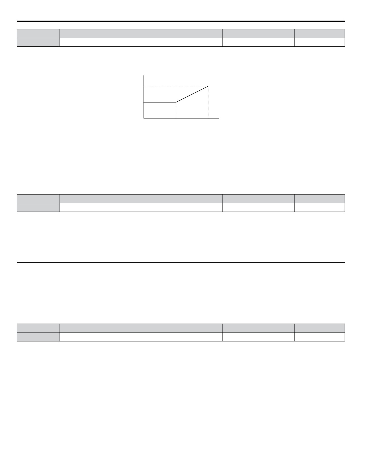
The slip compensation limit is constant throughout the constant torque range. In the constant power range it is increased based
on C3-03 and the output frequency as shown in the following diagram.
Note:
This parameter is disabled when using V/f Control with Simple PG Feedback Control (H6-01 = 3).
E1-04
× C3-03
E1-06
C3-03
output frequency
E1-06
E1-04
Base
Maximum
Frequency
Frequency
Figure 5.28 Slip Compensation Limit
n C3-04: Slip Compensation Selection during Regeneration
When the slip compensation during regeneration function has been activated and regenerative load is applied, it might be
necessary to use a braking option (braking resistor, braking resistor unit, or braking unit).
Even if enabled, this function does not operate when the output frequency is too low.
No.
Parameter Name
Setting Range
Default
C3-04
Slip Compensation Selection during Regeneration
0 or 1
0
Setting 0: Disabled
Slip compensation is not provided. Depending on the load and operation mode (motoring or regenerative) the actual motor
speed will be lower or higher than the frequency reference.
Setting 1: Enabled
Slip compensation is enabled during regenerative operation. It will not be active at output frequencies below 6 Hz.
u C4: Torque Compensation
The torque compensation function compensates for insufficient torque production at start-up or when a load is applied.
Note:
Before making changes to the torque compensation parameters make sure the motor parameters and V/f pattern are set properly or perform
Auto-Tuning.
n C4-01: Torque Compensation Gain
Sets the gain for the torque compensation function.
No.
Parameter Name
Setting Range
Default
C4-01
Torque Compensation Gain
0.00 to 2.50
1.00
Torque Compensation in V/f
The drive calculates the motor primary voltage loss using the output current and the termination resistor value and adjusts the
output voltage to compensate insufficient torque at start or when load is applied. The effects of this voltage compensation can
be increased or decreased using parameter C4-01.
Adjustment
Although this parameter rarely needs to be changed, it may be necessary to adjust the torque compensation gain in small steps
of 0.05 in the following situations:
• Increase this setting when using a long motor cable.
• Decrease this setting when motor oscillation occurs.
Adjust C4-01 so the output current does not exceed the drive rated current.
n C4-02: Torque Compensation Primary Delay Time 1
Sets the delay time used for applying torque compensation.
144
5.3 C: Tuning
No.
Parameter Name
Setting Range
Default
C4-02
Torque Compensation Primary Delay Time 1
0 to 60000 ms
200 ms
Adjustment
Although C4-02 rarely needs to be changed, adjustments may be necessary in the following situations:
• Increase this setting if the motor vibrates.
• Decrease this setting if the motor responds too slowly to changes in the load.
u C6: Carrier Frequency
n C6-02: Carrier Frequency Selection
Parameter C6-02 sets the switching frequency of the drive’s output transistors. It can be changed in order to reduce audible
noise and also reduce leakage current.
Note:
The drive rated current is reduced when the carrier frequency is set higher than the default value.
No.
Parameter Name
Setting Range
Default
C6-02
Carrier Frequency Selection
1 to B; F
7
Settings:
C6-02
Carrier Frequency
C6-02
Carrier Frequency
1
2.0 kHz
8
Swing PWM 2
2
5.0 kHz
9
Swing PWM 3
3
8.0 kHz
A
Swing PWM 4
4
10.0 kHz
B <1>
Leakage Current Rejection PWM
5
12.5 kHz
F
User-defined (C6-03 to C6-05)
6
15.0 kHz
7
Swing PWM 1
<1> Setting B uses a PWM pattern that reduces the amount of leakage current detected over long wiring distances. This can help reduce alarm detection
and problems with the current monitor that result from leakage current over long wiring distances. This is the same as setting the carrier frequency
to 2 kHz.
Note:
Swing PWM uses 2.0 kHz carrier frequency as a base. Applying special PWM patterns minimizes the audible noise of the motor.
Guidelines for Carrier Frequency Parameter Setup
Symptom
Remedy
Speed and torque are unstable at low speeds.
Noise from the drive is affecting peripheral devices.
Lower the carrier frequency.
Excessive leakage current from the drive.
• Lower the carrier frequency
Wiring between the drive and motor is too long. <1>
• Set C6-02 to B if an alarm is detected or if leakage current causes a
problem with the current monitor.
Audible motor noise is too loud.
Increase the carrier frequency or use Swing PWM. <2>
<1> The carrier frequency may need to be lowered if the motor cable is too long. Refer to the table below.
<2> Default setting is 7 (Swing PWM), equivalent to setting 2 kHz. Increasing the carrier frequency is fine, but remember that the drive rated current
falls when the carrier frequency is increased.
5
145
5.3 C: Tuning
n C6-03/C6-04/C6-05: Carrier Frequency Upper Limit/Lower Limit/Proportional Gain
Use these parameters to set a user defined or a variable carrier frequency. To set the upper and lower limits, first set C6-02 to
“F”.
No.
Parameter Name
Setting Range
Default
C6-03
Carrier Frequency Upper Limit
1.0 to 15.0 kHz
2.0 kHz
C6-04
Carrier Frequency Lower Limit
1.0 to 15.0 kHz
2.0 kHz
C6-05
Carrier Frequency Proportional Gain
0 to 99
0
Setting a Fixed User Defined Carrier Frequency
A carrier frequency between the fixed selectable values can be entered in parameter C6-03 when C6-02 is set to “F”. In V/f
Control, parameter C6-04 must also be adjusted to the same value as C6-03.
Setting a Variable Carrier Frequency
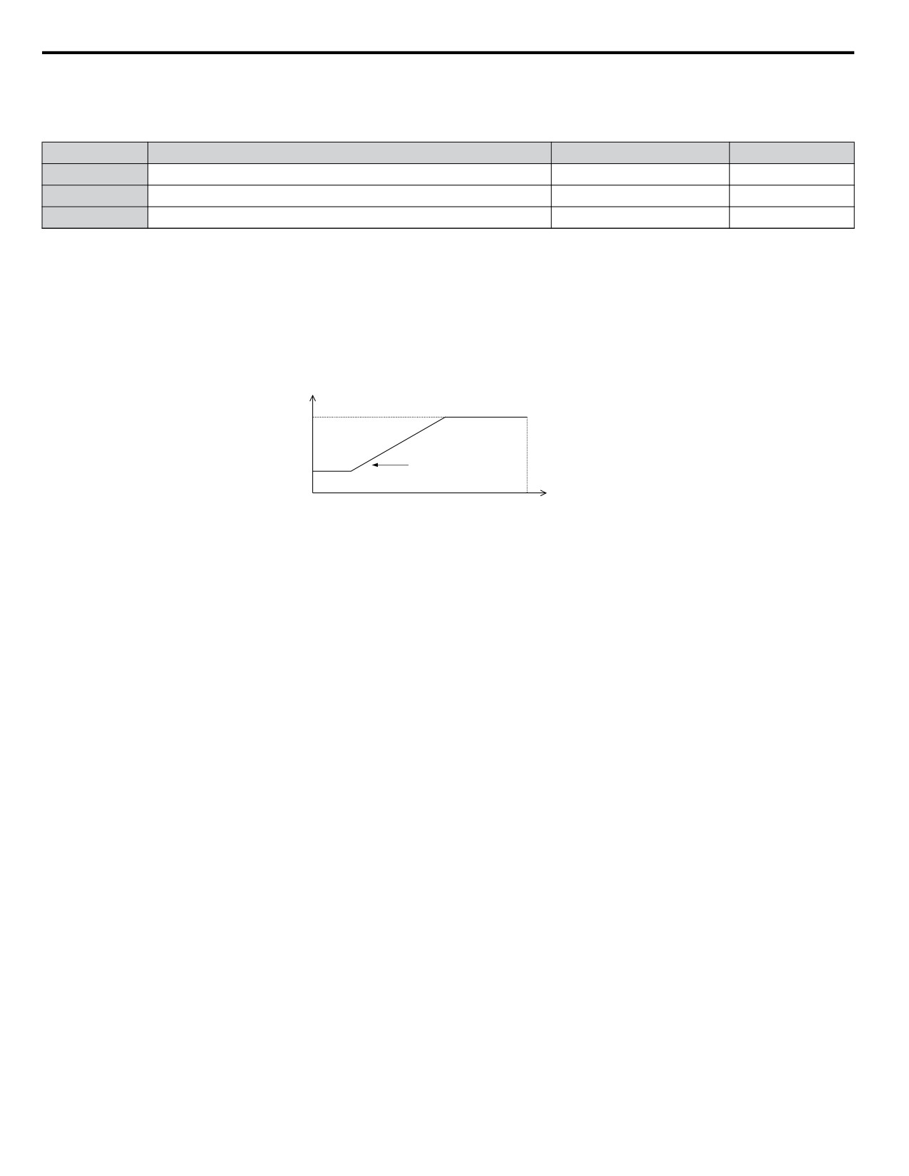
In V/f Control, the carrier frequency can be set up to change linearly with the output frequency. In this case the upper and
lower limits for the carrier frequency and the carrier frequency proportional gain (C6-03, C6-04, C6-05) have to be set as
shown in Figure 5.29.
Carrier Frequency
C6-03
Output
C6-04
Frequency
x C6-05 x K*
Output Frequency
E1-04
Max Output Frequency
Figure 5.29 Carrier Frequency Changes Relative to Output Frequency
K is a coefficient determined by the value of C6-03:
•
10.0 kHz > C6-03 ≥ to 5.0 kHz: K = 2
•
5.0 kHz > C6-03: K = 1
• C6-03 ≥ 10.0 kHz: K = 3
Note:
1. A carrier frequency error (oPE11) will occur when the carrier frequency proportional gain is greater than 6 while C6-03 is less than
C6-04.
2. When C6-05 is set lower than 7, C6-04 is disabled and the carrier frequency will be fixed to the value set in C6-03.
146
5.4 d: Reference Settings
5.4
d: Reference Settings
u d1: Frequency Reference
n d1-01 to d1-17: Frequency Reference 1 to 16 and Jog Reference
Up to 17 preset references (including Jog reference) can be programmed in the drive. The references can be switched during
Run by digital inputs. The acceleration/deceleration to the new reference is performed using the active acceleration/deceleration
time.
The Jog frequency must be selected by a separate digital input and has priority over the references 1 to 16.
The multi-speed references 1 and 2 can be provided by analog inputs.
No.
Parameter Name
Setting Range
Default
d1-01 to d1-16
Frequency Reference 1 to 16
0.00 to 400.00 Hz <1>
0.00 Hz
d1-17
Jog Frequency Reference
0.00 to 400.00 Hz <1>
6.00 Hz
<1> The upper limit is determined by the maximum output frequency (E1-04) and upper limit for the frequency reference (d2-01).
Multi-Step Speed Selection
Depending on how many speeds are used, some digital inputs have to be programmed for Multi-Step Speed Reference 1, 2,
3 and 4 (H1-oo = 3, 4, 5, 32). For the Jog reference a digital input must be set to H1-oo = 6.
Notes on using analog inputs as multi-speed 1 and 2:
• If the frequency reference source is assigned to analog input A1 (b1-01 = 1), then this input will be used for Frequency
Reference 1 instead of d1-01. If the reference source is assigned to the digital operator (b1-01 = 0), then d1-01 will be used
as Frequency Reference 1.
• When the analog input A2 function is set to “Auxiliary Frequency” (H3-10 = 2), then the value input to terminal A2 will be
used as the Frequency Reference 2 instead of the value set to parameter d1-02. When H3-10 does not equal 2, then d1-02
becomes the reference for Frequency Reference 2.
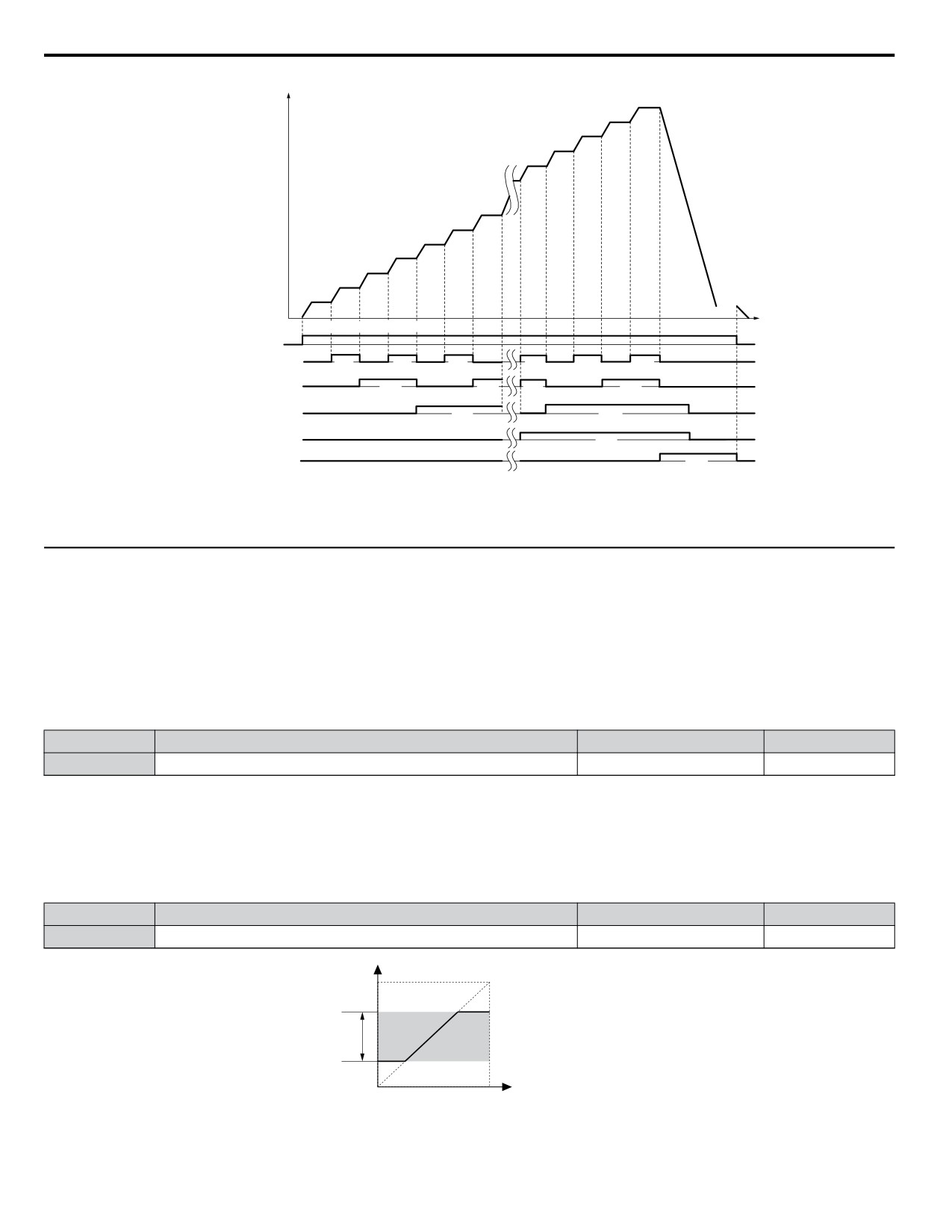
The different speed references can be selected as shown in Table 5.10. Figure 5.30 illustrates the multi-step speed selection.
Table 5.10 Multi-Step Speed Reference and Terminal Switch Combinations
Multi-Step
Multi-Step
Multi-Step
Multi-Step
Jog Reference
Reference
Speed
Speed 2
Speed 3
Speed 4
H1-oo=6
H1-oo=3
H1-oo=4
H1-oo=5
H1-oo=32
Frequency Reference 1 (d1-01/A1)
OFF
OFF
OFF
OFF
OFF
Frequency Reference 2 (d1-02/A2)
ON
OFF
OFF
OFF
OFF
Frequency Reference 3 (d1-03)
OFF
ON
OFF
OFF
OFF
Frequency Reference 4 (d1-04)
ON
ON
OFF
OFF
OFF
Frequency Reference 5 (d1-05)
OFF
OFF
ON
OFF
OFF
Frequency Reference 6 (d1-06)
ON
OFF
ON
OFF
OFF
Frequency Reference 7 (d1-07)
OFF
ON
ON
OFF
OFF
Frequency Reference 8 (d1-08)
ON
ON
ON
OFF
OFF
Frequency Reference 9 (d1-09)
OFF
OFF
OFF
ON
OFF
Frequency Reference 10 (d1-10)
ON
OFF
OFF
ON
OFF
Frequency Reference 11 (d1-11)
OFF
ON
OFF
ON
OFF
5
Frequency Reference 12 (d1-12)
ON
ON
OFF
ON
OFF
Frequency Reference 13 (d1-13)
OFF
OFF
ON
ON
OFF
Frequency Reference 14 (d1-14)
ON
OFF
ON
ON
OFF
Frequency Reference 15 (d1-15)
OFF
ON
ON
ON
OFF
Frequency Reference 16 (d1-16)
ON
ON
ON
ON
OFF
Jog Frequency Reference (d1-17) <1>
−
−
−
−
ON
<1> The Jog frequency overrides the frequency reference being used.
147
5.4 d: Reference Settings
Frequency
d1-15d1-16
d1-14
reference
d1-13
d1-12
d1-07
d1-06
d1-05
d1-04
d1-03
d1-02
d1-01 (A2)
(A1)
d1-17
FWD (REV) Run/Stop
Time
ON
Multi-step Speed Ref. 1
ON
ON
ON
ON ON ON
Multi-step Speed Ref. 2
ON
ON
ON
ON
Multi-step Speed Ref. 3
ON
ON
Multi-step Speed Ref. 4
ON
Jog Reference
ON
Figure 5.30 Preset Reference Timing Diagram
u d2: Frequency Upper/Lower Limits
By entering upper or lower frequency limits, the drive programmer can prevent operation of the drive above or below levels
that may cause resonance and or equipment damage.
n d2-01: Frequency Reference Upper Limit
Sets the maximum frequency reference as a percentage of the maximum output frequency. This limit applies to all frequency
references.
Even if the frequency reference is set to a higher value, the drive internal frequency reference will not exceed this value.
No.
Parameter Name
Setting Range
Default
d2-01
Frequency Reference Upper Limit
0.0 to 110.0%
100.0%
n d2-02: Frequency Reference Lower Limit
Sets the minimum frequency reference as a percentage of the maximum output frequency. This limit applies to all frequency
references.
If a lower reference than this value is input, the drive will run at the d2-02 level. If the drive is started with a lower reference
than d2-02, it will accelerate up to d2-02.
No.
Parameter Name
Setting Range
Default
d2-02
Frequency Reference Lower Limit
0.0 to 110.0%
0.0%
Internal frequency
reference
d2-01
Frequency Reference Upper Limit
Operating
range
Frequency Reference Lower Limit
d2-02
Set frequency reference
Figure 5.31 Frequency Reference: Upper and Lower Limits
148
5.4 d: Reference Settings
n d2-03: Master Speed Reference Lower Limit
Unlike frequency reference lower limit (d2-02) which will affect the frequency reference no matter where it is sourced from
(i.e., analog input, preset speed, Jog speed, etc.), the master speed lower limit (d2-03) sets a lower limit that will only affect
the analog input (terminals A1 and A2) that is the active master speed frequency.
Set as a percentage of the maximum output frequency.
Note:
The lower limits for the Jog frequency, multi-step speed settings, and 2-step speed settings do not change. When lower limits are set to both
the frequency reference (d2-02) and the main frequency reference (d2-03), the drive uses the greater of those two values as the lower limit.
No.
Parameter Name
Setting Range
Default
d2-03
Master Speed Reference Lower Limit
0.0 to 110.0%
0.0%
n E2-01: Motor Rated Current
Provides motor control, protects the motor, and calculates torque limits. Set E2-01 to the full load amps (FLA) stamped on
the motor nameplate. If Auto-Tuning completes successfully, the value entered to T1-04 will automatically be saved to E2-01.
No.
Parameter Name
Setting Range
Default
10% to 200% of the drive
Determined by
E2-01
Motor Rated Current
rated current <1>
o2-04
<1> Display is in the following units:
BV0006 to BV0018, 2V0006 to 2V0040, and 4V0002 to 4V0023: 0.01 A units.
2V0056 to 2V0069 and 4V0031 to 4V0038: 0.1 A units.
Note:
An oPE02 error will occur if the motor rated current in E2-01 is set lower than the motor no-load current in E2-03. Set E2-03 correctly to
prevent this error.
u d3: Jump Frequency
n d3-01 to d3-04: Jump Frequencies 1, 2, 3, and Jump Frequency Width
In order to avoid continuous operation at a speed that causes resonance in driven machinery, the drive can be programmed
with three separate Jump frequencies that will not allow continued operation within specific frequency ranges. If the speed
reference falls within a Jump frequency dead band, the drive will clamp the frequency reference just below the dead band and
only accelerate past it when the frequency reference rises above the upper end of the dead band.
Setting parameters d3-01 through d3-03 to 0.0 Hz disables the Jump frequency function.
No.
Parameter Name
Setting Range
Default
d3-01
Jump Frequency 1
0.0 to 400.0 Hz
0.0 Hz
d3-02
Jump Frequency 2
0.0 to 400.0 Hz
0.0 Hz
d3-03
Jump Frequency 3
0.0 to 400.0 Hz
0.0 Hz
d3-04
Jump Frequency Width
0.0 to 20.0 Hz
1.0 Hz
Figure 5.32 shows the relationship between the Jump frequency and the output frequency.
5
149
5.4 d: Reference Settings
Output
frequency
Frequency
reference
decreases
Frequency
reference
increases
Jump
Frequency
Width (d3-04)
Jump
Frequency
Width (d3-04)
Jump
Frequency
Width (d3-04)
Jump
Jump
Jump
Frequency
reference
Frequency 3
Frequency 2
Frequency 1
d3-03
d3-02
d3-01
Figure 5.32 Jump Frequency Operation
Note:
1. The drive will use the active accel/decel time to pass through the specified dead band range but will not allow continuous operation in
that range.
2. When using more than one Jump frequency, make sure that d3-01 ≥ d3-02 ≥ d3-03.
u d4: Frequency Hold and Up/Down 2 Function
n d4-01: Frequency Reference Hold Function Selection
This parameter is effective when either of the digital input functions listed below is used.
• Accel/decel ramp hold function (H1-oo= A)
• Up/Down function (H1-oo = 10 and 11, sets the frequency reference by digital inputs)
• Up/Down 2 function (H1-oo = 75/76, adds a bias to the frequency reference using digital inputs)
Parameter d4-01 determines whether the frequency reference or the frequency bias (Up/Down 2) value is saved when the Run
command is cleared or the power supply is shut down.
No.
Parameter Name
Setting Range
Default
d4-01
Frequency Reference Hold Function Selection
0 or 1
0
The operation depends on with what function parameter d4-01 is used.
Setting 0: Disabled
• Acceleration Hold
The hold value will be reset to 0 Hz when the Run command is canceled or the drive power is switched off. The active
frequency reference will be the value the drive uses when it restarts.
• Up/Down
The frequency reference value will be reset to 0 Hz when the Run command is canceled or the drive power is switched off.
The drive will start from 0 Hz when restarted.
• Up/Down 2
The frequency bias is not saved when the Run command is switched off or 5 s after the Up/Down 2 command has been
released. The Up/Down 2 function will start with a bias of 0% when the drive is restarted.
Setting 1: Enabled
• Acceleration Hold
The last hold value will be saved when the Run command or the drive power is switched off. The drive will use the value
that was saved as the frequency reference when it restarts. The accel/decel hold input must be enabled the entire time or else
the hold value will be cleared.
150
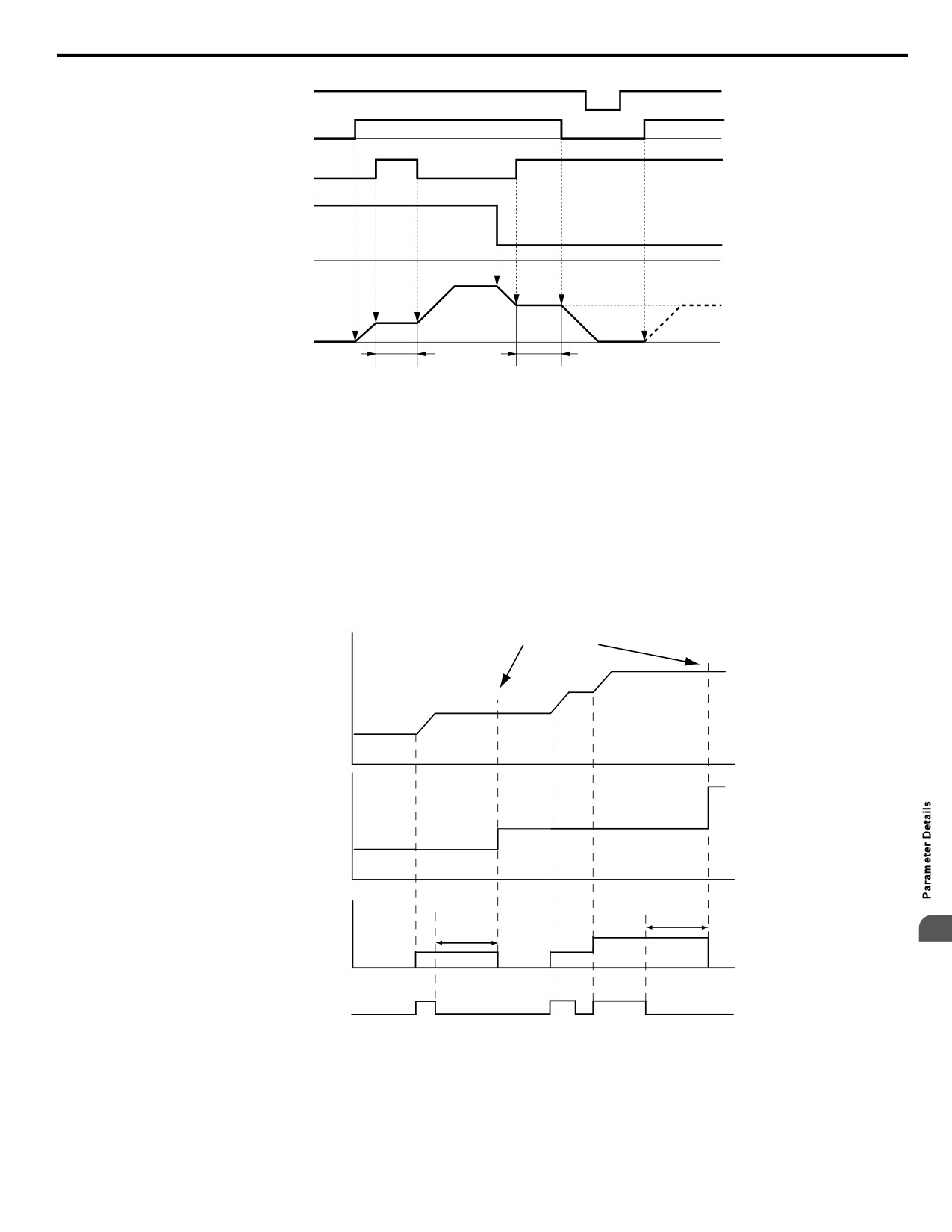
5.4 d: Reference Settings
ON
ON
Power supply
OFF
OFF
ON
OFF
ON
Forward Run / Stop
OFF
ON
OFF
ON
Hold Accel/Decel
Frequency reference
Output frequency
d4-01 = 1
d4-01 = 0
Hold
Hold
Figure 5.33 Frequency Reference Hold with Accel/Decel Hold Function
• Up/Down
The frequency reference value will be saved when the Run command or the drive power is switched off. The drive will use
the frequency reference that was saved when it restarts.
• Up/Down 2 with Frequency Reference from Digital Operator
When the digital operator is selected as the frequency reference source, the bias will be added to the frequency reference
that was selected 5 s after the Up/Down 2 command has been released, and then reset to 0 afterwards. The new frequency
reference value is then saved. When the Run command or the power supply is switched off, the drive will use the value that
was when it restarts.
Bias is added to frequency
reference and reset to 0
Output
frequency
Frequency
reference
Bias
5 s
5 s
5
Up 2 command
Figure 5.34 Up/Down 2 Example with Reference from Digital Operator and d4-01 = 1
• Up/Down 2 with Frequency Reference from Other Input Sources
When the frequency reference is set by an another source than the digital operator, the bias value will be saved in parameter
d4-06 exactly 5 s after the Up/Down 2 command has been released. When the Run command is turned off or the power is
switched off, the drive will use the value saved in d4-06 when it restarts.
151
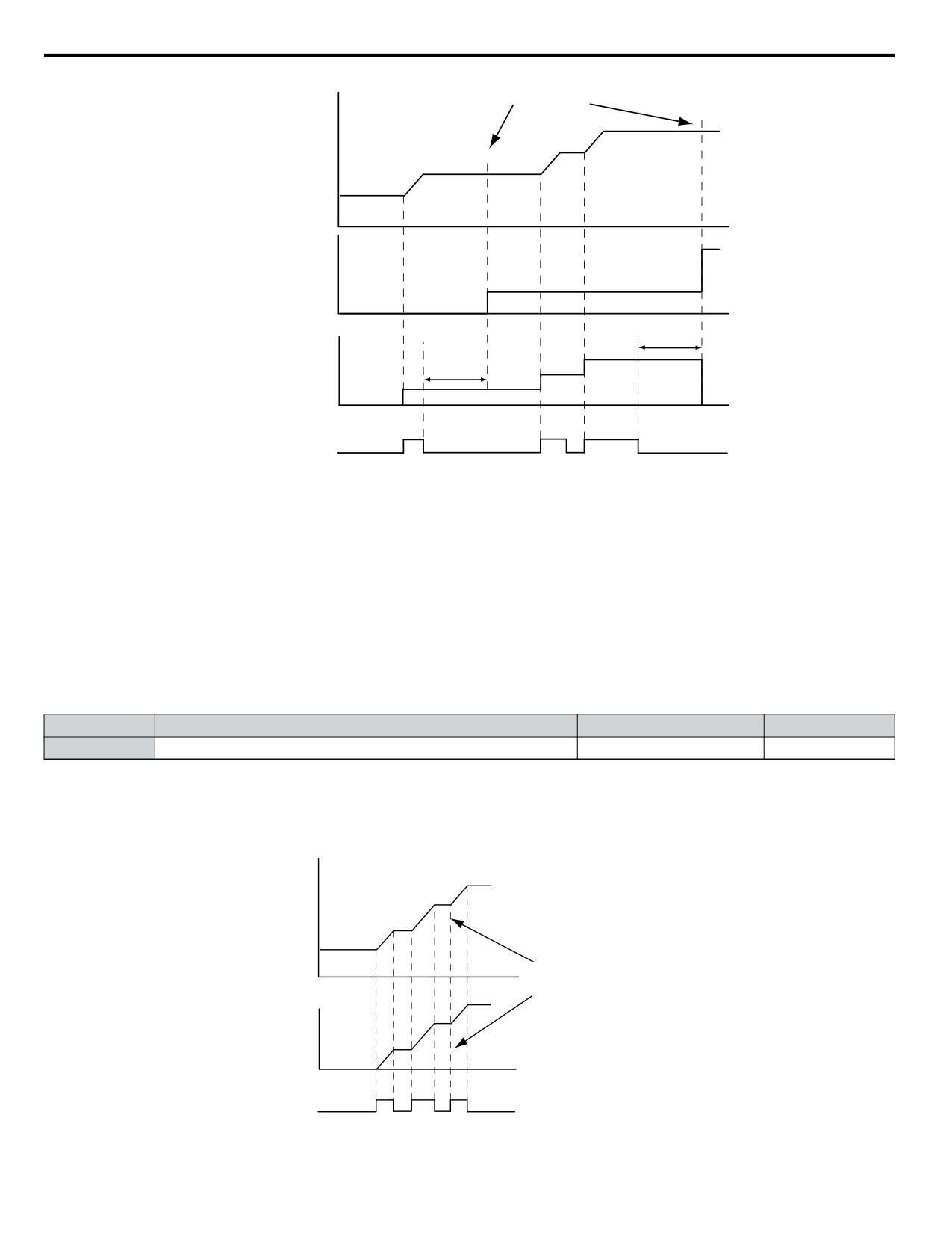
5.4 d: Reference Settings
Bias is saved in parameter d4-06
Output
frequency
d4-06 value
5 s
Bias
5 s
Up 2 command
Figure 5.35 Up/Down 2 Example with Other Reference than Digital Operator and d4-01 = 1
Note:
Make sure to set the Up/Down 2 limits properly when using d4-01 = 1 in combination with the Up/Down 2 function. Refer to d4-08:
Frequency Reference Bias Upper Limit (Up/Down 2) on page 154 and Refer to d4-09: Frequency Reference Bias Lower Limit (Up/
Down 2) on page 154 for details on the limit settings.
Clearing the Value that was Saved
Depending on which function is used, the frequency reference value that was saved can be cleared by:
• Releasing the acceleration hold input.
• Setting an Up or Down command while no Run command is active.
n d4-03: Frequency Reference Bias Step (Up/Down 2)
Sets the bias that is added to or subtracted from the frequency reference by the Up/Down 2 function.
No.
Parameter Name
Setting Range
Default
d4-03
Frequency Reference Bias Step
0.00 to 99.99 Hz
0.00 Hz
The operation depends on the set value:
Setting d4-03 = 0.0 Hz
While the Up 2 or Down 2 command is enabled, the bias value is increased or decreased using the accel/decel time determined
by parameter d4-04.
Output
frequency
Bias value is increased using the
accel/decel times as set in d4-04
Bias
Up 2 command
Figure 5.36 Up/Down 2 Bias when d4-03 = 0.0 Hz
152
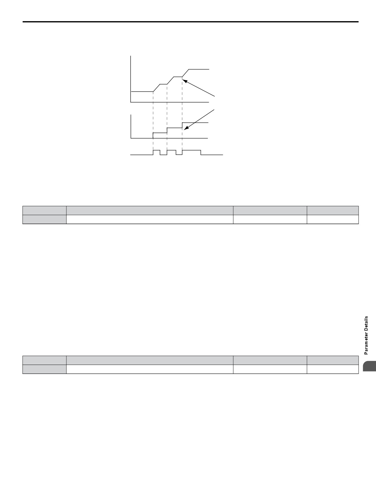
5.4 d: Reference Settings
Setting d4-03 > 0.0 Hz
When an Up 2 or Down 2 command is enabled, the bias is increased or decreased in steps for the value set in d4-03. The
frequency reference changes with the accel/decel times determined by parameter d4-04.
Output
frequency
Bias value is increased in steps as
defined in d4-03
Drive uses accel/decel times as
set in d4-04
Bias
Up 2 command
Figure 5.37 Up/Down 2 Bias when d4-03 > 0.0 Hz
n d4-05: Frequency Reference Bias Operation Mode Selection (Up/Down 2)
Determines if the bias value is held or not when the Up/Down 2 inputs are both released or both enabled. The parameter is
effective only when parameter d4-03 is set to 0.00.
No.
Parameter Name
Setting Range
Default
d4-05
Frequency Reference Bias Operation Mode Selection
0 or 1
0
Setting 0: Hold Bias Value
The bias value will be held if no input Up 2 or Down 2 is active.
Setting 1: Reset Bias Value
The bias is reset to 0% when both inputs Up 2 and Down 2 are either on or off. The drive will use the accel/decel time as
selected in d4-04 to accelerate or decelerate to the frequency reference value.
n d4-06: Frequency Reference Bias (Up/Down 2)
This parameter is used to save the frequency reference bias value set by the Up/Down 2 function. It is set as a percentage of
the maximum output frequency. The function of d4-06 depends on how the Up/Down 2 function is configured.
• This parameter is not normally used when the frequency reference is set by the digital operator. The user can set d4-06 to a
certain value that will be applied when the operation is started, but it will be reset when the frequency reference changes
(including multi-step references) or will be disabled when d4-01 = 0 and the Run command is removed.
• When d4-01 = 0 and the frequency reference is set by an analog or pulse input, the value set in d4-06 is generally added to
or subtracted from the frequency reference.
• When d4-01 = 1 and the frequency reference is set by a different source than the digital operator, the bias value adjusted
with the Up/Down 2 inputs is stored in d4-06 when 5 s have passed after the Up 2 or Down 2 command release.
No.
Parameter Name
Setting Range
Default
5
d4-06
Frequency Reference Bias
-99.9 to 100.0%
0.0%
Conditions that Generally Reset or Disable Parameter d4-06
• When the Up/Down 2 function has not been assigned to the multi-function terminals
• When the frequency reference source has been changed (including LOCAL/REMOTE or external reference 1/external
reference 2 switch over by digital inputs)
• If d4-03 = 0 Hz, d4-05 = 1 and the Up/Down 2 commands are both open or both closed
• Any changes to the maximum frequency set to E1-04
153
5.4 d: Reference Settings
n d4-07: Analog Frequency Reference Fluctuation Limit (Up/Down 2)
This parameter is for handling changes in the frequency reference while the terminal set for Up 2 or Down 2 is enabled. If the
frequency reference changes for more than the level set to d4-07, then the bias value will be held, and the drive will accelerate
or decelerate following the frequency reference. When the frequency reference is reached, the bias hold is released and the
bias follows the Up/Down 2 input commands.
Parameter d4-07 is applicable only if the frequency reference is set by an analog or pulse input.
No.
Parameter Name
Setting Range
Default
d4-07
Analog Frequency Reference Fluctuation Limit
0.1 to 100.0%
1.0%
n d4-08: Frequency Reference Bias Upper Limit (Up/Down 2)
Parameter d4-08 sets the upper limit of the Up/Down 2 bias (monitor U6-20) and the value that can be saved in parameter
d4-06. Set this parameter to an appropriate value before using the Up/Down 2 function.
Note:
When the frequency reference is set by the digital operator (b1-01 = 0) and d4-01 = 1, the bias value will be added to the frequency reference
if no Up/Down 2 command is received for 5 s, and will be reset to 0 afterwards. From that point the bias can be increased up to the limit
set in d4-08 again.
No.
Parameter Name
Setting Range
Default
d4-08
Frequency Reference Bias Upper Limit
0.0 to 100.0%
100.0%
n d4-09: Frequency Reference Bias Lower Limit (Up/Down 2)
Parameter d4-08 sets the lower limit of the Up/Down 2 bias (monitor U6-20) and the value that can be saved in parameter
d4-06. Set this parameter to an appropriate value before using the Up/Down 2 function.
Note:
When the frequency reference is set by the digital operator (b1-01 = 0) and d4-01 = 1, the bias value will be added to the frequency reference
if no Up/Down 2 command is received for 5 s, and will be reset to 0 afterwards. If the bias is increased using the Up 2 command, once it is
added to the frequency reference the speed cannot be reduced with a Down 2 command if the limit set in d4-09 is 0. In this case make sure
to set a negative lower limit in d4-09 to allow speed reduction.
No.
Parameter Name
Setting Range
Default
d4-09
Frequency Reference Bias Lower Limit
-99.9 to 0.0%
0.0%
n d4-10: Up/Down Frequency Reference Limit Selection
Selects how the lower frequency limit is set when the Up/Down function is used. Refer to Settings 10 and 11: Up/Down
Function on page 165 for details on the Up/Down function in combination with frequency reference limits.
Setting 0: Lower Limit is Determined by d2-02 or Analog Input
The lower frequency reference limit is determined by the higher value of both, parameter d2-02 or an analog input that is
programmed for “Frequency Bias” (H3-02/10 = 0).
Note:
If the external reference change over function (H1-oo = 2) used to switch between Up/Down function and analog input as reference source,
the analog value would become the lower reference limit when the Up/Down reference is active. Change d4-10 to 1 to make the Up/Down
function independent of the analog input value.
Setting 1: Lower Limit is Determined by Parameter d2-02
Only parameter d2-02 sets the lower frequency reference limit.
154
5.5 E: Motor Parameters
5.5
E: Motor Parameters
E parameters cover V/f pattern and motor data settings.
u E1: V/f Characteristics
n E1-01: Input Voltage Setting
Set the input voltage parameter to the nominal voltage of the AC power supply. This parameter adjusts the levels of some
protective features of the drive (overvoltage, Stall Prevention, etc.).
NOTICE: Set parameter E1-01 to match the input voltage of the drive. Drive input voltage (not motor voltage) must be set in E1-01 for the
protective features of the drive to function properly. Failure to comply could result in improper drive operation.
No.
Parameter Name
Setting Range
Default
E1-01 <1>
Input Voltage Setting
155 to 255 V
230 V
<1> The setting range and default value shown here are for 200 V class drives. Double this for 400 V class units.
E1-01 Related Values
The input voltage setting determines the over-/undervoltage detection level and the operation levels of the braking transistor
as well as the KEB function and the overvoltage suppression function.
(Approximate Values)
ov Suppression /
Setting Value of
Desired DC Bus
Voltage
ov Detection
BTR Operation
Uv Detection Level
Stall Prevention
E1-01
Voltage during KEB
Level
Level
(L2-05)
Level
(L2-11)
(L3-17)
190 V
200 V Class
all settings
410 V
394 V
(single-phase = 160
240 V
370 V
V)
setting ≥ 400 V
820 V
788 V
380 V
480 V
740 V
400 V Class
setting < 400 V
740 V
708 V
350 V
440 V
660 V
Note:
The braking transistor operation levels are valid for the drive internal braking transistor. If an external CDBR braking chopper is used, refer
to the instruction manual of that unit.
n V/f Pattern Settings
The drive utilizes a set V/f pattern to determine the appropriate output voltage level for each relative to the frequency reference.
There are 15 different preset V/f patterns to select from with varying voltage profiles, saturation levels (frequency at which
maximum voltage is reached), and maximum frequencies. Additionally, one custom V/f pattern can be set up by programming
parameters E1-04 through E1-10.
V/f Pattern Setup for V/f Control
1. Set the input voltage for the drive. Refer to E1-01: Input Voltage Setting on page 155.
2. Set the V/f pattern by:
a) choosing one of the 15 preset V/f patterns (E1-03 = 0 to E).
b) select the custom V/f pattern (E1-03 = F, default setting).
3. When using one of the 15 presets, E1-04 through E1-13 are automatically set. Refer to the description below.
5
For a custom V/f pattern, E1-04 through E1-13 must be adjusted manually. Refer to V/f Pattern Settings E1-04 to
E1-13 on page 158.
n E1-03: V/f Pattern Selection
This parameter can only be changed when the drive is operating in V/f Control. It allows the user to select the V/f pattern from
15 predefined patterns or to create a custom V/f pattern.
No.
Parameter Name
Setting Range
Default
E1-03
V/f Pattern Selection
0 to F
F
155
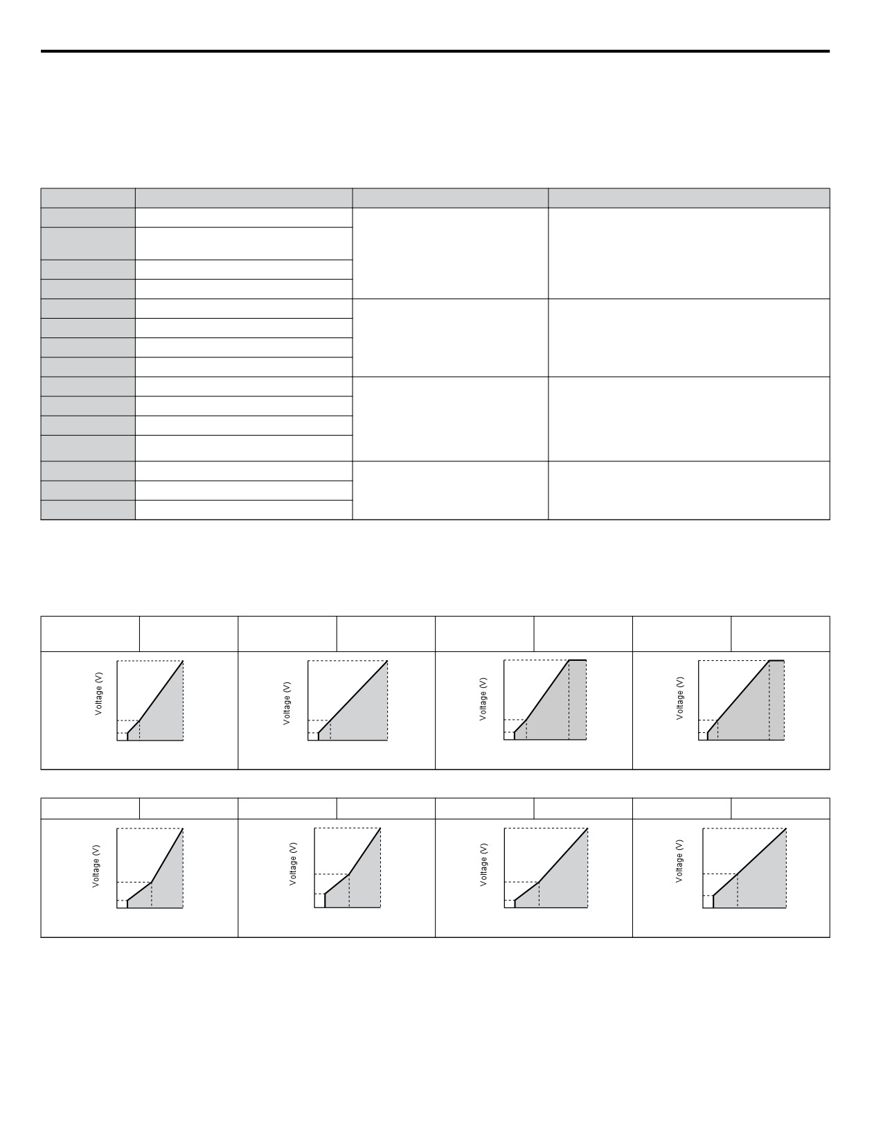
5.5 E: Motor Parameters
Setting the V/f Pattern
Choose the V/f pattern that meets the application demands from the table below. Set the correct value to E1-03. The V/f
parameters E1-04 to E1-13 can only be monitored, not changed.
Note:
1. Setting an improper V/f pattern may result in low motor torque or increased current due to overexcitation.
2. Parameter E1-03 is not reset when the drive is initialized.
Table 5.11 Predefined V/f Patterns
Setting
Specification
Characteristic
Application
0
50 Hz
60 Hz
1
For general purpose applications. Torque remains
(default setting)
Constant torque
constant regardless of changes to speed.
2
60 Hz (with 50 Hz base)
3
72 Hz (with 60 Hz base)
4
50 Hz, Heavy Duty 2
5
50 Hz, Heavy Duty 1
For fans, pumps, and other applications that require
Derated torque
6
60 Hz, Heavy Duty 1
torque derating relative to the load.
7
60 Hz, Heavy Duty 2
8
50 Hz, mid starting torque
Select high starting torque when:
9
50 Hz, high starting torque
• Wiring between the drive and motor exceeds
High starting torque
150 m
A
60 Hz, mid starting torque
• A large amount of starting torque is required
B
60 Hz, high starting torque
• An AC reactor is installed
C
90 Hz (with 60 Hz base)
When operating at greater than 60 Hz the output
D
120 Hz (with 60 Hz base)
Constant output
voltage will be constant.
E
180 Hz (with 60 Hz base)
The following tables show details on predefined V/f patterns.
The following graphs are for 200 V class drives; double the values for 400 V class drives.
Predefined V/f Patterns for 0.1 to 3.7 kW Drives
Table 5.12 Constant Torque Characteristics, Settings 0 to 3
60 Hz
Setting = 0
50 Hz
Setting = 1
Setting = 2
60 Hz
Setting = 3
72 Hz
(default)
200
200
200
200
16
16
16
16
12
12
12
12
0 1.3
2.5
50
0 1.5 3
60
0 1.5 3
50
60
0 1.5 3
60 72
Frequency (Hz)
Frequency (Hz)
Frequency (Hz)
Frequency (Hz)
Table 5.13 Derated Torque Characteristics, Settings 4 to 7
Setting = 4
50 Hz
Setting = 5
50 Hz
Setting = 6
60 Hz
Setting = 7
60 Hz
200
200
200
200
50
50
35
35
9
9
8
8
0 1.3
25
50
0 1.3
25
50
0 1.5
30
60
0 1.5
30
60
Frequency (Hz)
Frequency (Hz)
Frequency (Hz)
Frequency (Hz)
156
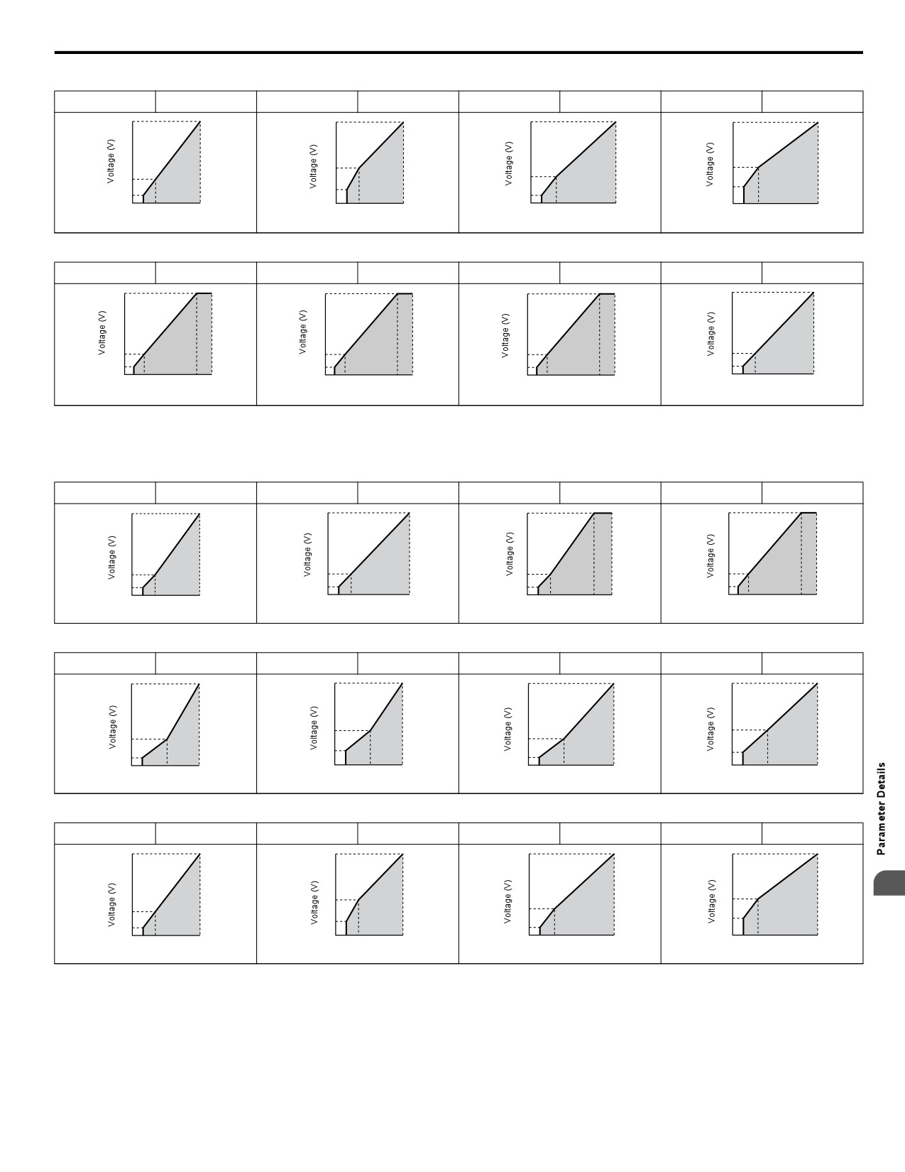
5.5 E: Motor Parameters
Table 5.14 High Starting Torque, Settings 8 to B
Setting = 8
50 Hz
Setting = 9
50 Hz
Setting = A
60 Hz
Setting = B
60 Hz
200
200
200
200
24
24
19
19
15
13
12
12
0 1.32.5
50
0 1.32.5
50
0 1.5
3
60
0 1.5
3
60
Frequency (Hz)
Frequency (Hz)
Frequency (Hz)
Frequency (Hz)
Table 5.15 Rated Output Operation, Settings C to F
Setting = C
90 Hz
Setting = D
120 Hz
Setting = E
180 Hz
Setting = F
60 Hz
200
200
200
200
16
16
16
16
12
12
12
12
0 1.5 3
60 90
0 1.5 3
60120
0 1.5 3
60180
0 1.5 3
60
Frequency (Hz)
Frequency (Hz)
Frequency (Hz)
Frequency (Hz)
Predefined V/f Patterns for 5.5 to 18.5 kW Drives
The following graphs are for 200 V class drives. Double values when using a 400 V class drive.
Table 5.16 Rated Torque Characteristics, Settings 0 to 3
Setting = 0
50 Hz
Setting = 1
60 Hz
Setting = 2
60 Hz
Setting = 3
72 Hz
200
200
200
200
14
14
14
14
7
7
7
7
0 1.3
2.5
50
0 1.5 3
60
0 1.5 3
50
60
0 1.5 3
60 72
Frequency (Hz)
Frequency (Hz)
Frequency (Hz)
Frequency (Hz)
Table 5.17 Derated Torque Characteristics, Settings 4 to 7
Setting = 4
50 Hz
Setting = 5
50 Hz
Setting = 6
60 Hz
Setting = 7
60 Hz
200
200
200
200
50
50
35
35
7
7
6
6
0 1.3
25
50
0 1.3
25
50
0 1.5
30
60
0 1.5
30
60
Frequency (Hz)
Frequency (Hz)
Frequency (Hz)
Frequency (Hz)
Table 5.18 High Starting Torque, Settings 8 to B
Setting = 8
50 Hz
Setting = 9
50 Hz
Setting = A
60 Hz
Setting = B
60 Hz
200
200
200
200
5
23
23
18
18
11
13
9
9
0 1.32.5
50
0 1.32.5
50
0 1.5
3
60
0 1.5
3
60
Frequency (Hz)
Frequency (Hz)
Frequency (Hz)
Frequency (Hz)
157
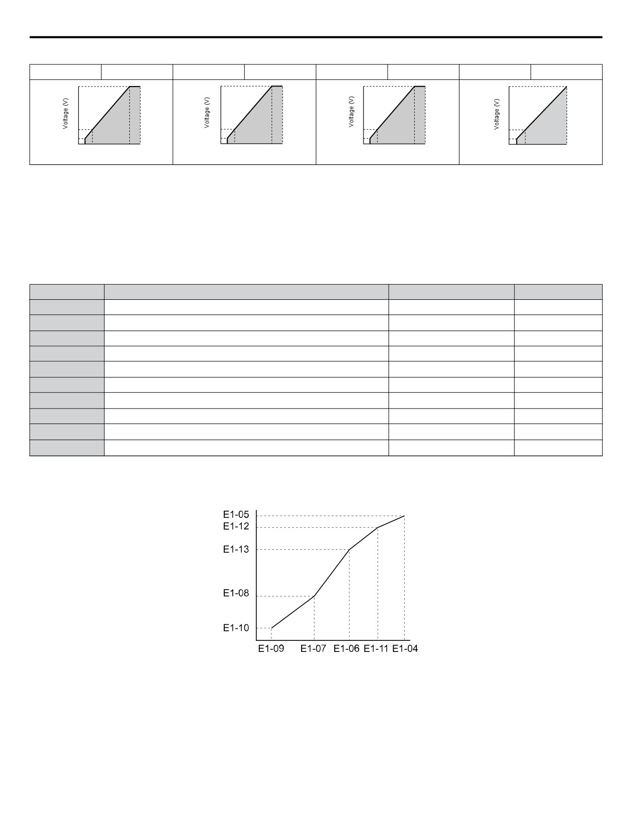
5.5 E: Motor Parameters
Table 5.19 Constant Output, Settings C to F
Setting = C
90 Hz
Setting = D
120 Hz
Setting = E
180 Hz
Setting = F
60 Hz
200
200
200
200
14
14
14
14
7
7
7
7
0 1.5 3
60 90
0 1.5 3
60120
0 1.5 3
60180
0 1.5 3
60
Frequency (Hz)
Frequency (Hz)
Frequency (Hz)
Frequency (Hz)
Setting a Custom V/f Pattern
Setting parameter E1-03 to “F” allows to set up a custom V/f pattern by changing parameters E1-04 to E1-13.
When E1-03 is changed to “F”, the default values for parameters E1-04 to E1-13 will be equal to V/f pattern 1 of the predefined
patterns.
n V/f Pattern Settings E1-04 to E1-13
Using parameters E1-04 through E1-13, the user can either monitor the V/f pattern values if E1-03 ≤ 15 or set up a custom V/
f pattern as shown in Figure 5.38 when E1-03 = F.
No.
Parameter Name
Setting Range
Default
E1-04
Maximum Output Frequency
40.0 to 400.0 Hz
60.0 Hz
E1-05
Maximum Voltage
0.0 to 255.0 V <1>
230 V <1>
E1-06
Base Frequency
0.0 to E1-04
60.0 Hz
E1-07
Middle Output Frequency
0.0 to E1-04
3.0 Hz
E1-08
Middle Output Frequency Voltage
0.0 to 255.0 V <1>
18.4 V <1>
E1-09
Minimum Output Frequency
0.0 to E1-04
1.5 Hz
E1-10
Minimum Output Frequency Voltage
0.0 to 255.0 V <1>
13.8 V <1>
E1-11
Middle Output Frequency 2
0.0 to E1-04
0.0 Hz
E1-12
Middle Output Frequency Voltage 2
0.0 to 255.0 V <1>
0.0 V
E1-13 <2>
Base Voltage
0.0 to 255.0 Hz
0.0 V
<1> Values shown are for 200 V class drives; double the value when using 400 V class drives.
<2> When E1-13 is set to 0.0 V, the drive uses the value set in E1-05 to control the voltage.
Output Voltage (V)
Frequency (Hz)
Figure 5.38 V/f Pattern
Note:
1. The following condition must be true when setting up the V/f pattern: E1-09 ≤ E1-07 < E1-06 ≤ E1-11 ≤ E1-04
2. Setting E1-11 to 0 disables both E1-11 and E1-12 and the above conditions do not apply.
3. To make the V/f pattern a straight line set E1-09 = E1-07. In this case the E1-08 setting is disregarded.
4. E1-03 is unaffected when the drive is initialized using parameter A1-03, but the settings for E1-04 through E1-13 are returned to their
default values.
158
5.5 E: Motor Parameters
u E2: Motor 1 Parameters
These parameters contain the most important motor data needed for optimal motor control. The parameters are set automatically
during Auto-Tuning. Set the parameters manually when Auto-Tuning cannot be performed.
n E2-01: Motor Rated Current
Set E2-01 to the full load amps (FLA) stamped on the motor nameplate. During Auto-Tuning the value must be entered to
parameter T1-04. If Auto-Tuning completes successfully, the value entered will automatically be saved to E2-01.
No.
Parameter Name
Setting Range
Default
10% to 200% of the drive
Depending on
E2-01
Motor Rated Current
rated current.
o2-04
(unit: 0.01 A)
Note:
1. Display is in the following units:
BV0006 to BV0018, 2V0006 to 2V0040, and 4V0002 to 4V0023: 0.01 A units.
2V0056 to 2V0069 and 4V0031 to 4V0038: 0.1 A units.
2. Change E2-01 only after changing the value set to E2-03. Setting E2-01 < E2-03 will trigger an oPE02 error.
n E2-02: Motor Rated Slip
Sets the motor rated slip in Hz. This value is automatically set during Rotational Auto-Tuning.
No.
Parameter Name
Setting Range
Default
Depending on
E2-02
Motor Rated Slip
0.00 to 20.00 Hz
o2-04
If Auto-Tuning cannot be performed calculate the motor rated slip using the information written on the motor nameplate and
the formula below:
E2-02 = f - (n x p)/120
(f: rated frequency (Hz), n: rated motor speed (r/min), p: number of motor poles)
n E2-03: Motor No-Load Current
Set E2-03 to the motor no-load current at rated voltage and rated frequency. If Rotational Auto-Tuning completes successfully,
this value is automatically calculated. If Auto-Tuning cannot be performed, contact the motor manufacturer for information
about the no-load current.
No.
Parameter Name
Setting Range
Default
0 to [E2-01]
Depending on
E2-03
Motor No-Load Current
(unit: 0.01 A)
o2-04
Note:
Display is in the following units: BV0006 to BV0018, 2V0006 to 2V0040, and 4V0002 to 4V0023: 0.01 A units. 2V0056 to 2V0069 and
4V0031 to 4V0038: 0.1 A units.
n E2-04: Number of Motor Poles
Set the number of motor poles to E2-04. If Auto-Tuning completes successfully, the value entered to T1-06 will automatically
be saved to E2-04.
No.
Parameter Name
Setting Range
Default
E2-04
Number of Motor Poles
2 to 48
2
5
n E2-05: Motor Line-to-Line Resistance
Sets the line-to-line resistance of the motor stator winding. If the Auto-Tuning completes successfully, this value is
automatically calculated. Remember this value must be entered as line-line and not line-neutral.
No.
Parameter Name
Setting Range
Default
Depending on
E2-05
Motor Line-to-Line Resistance
0.000 to 65.000 Ω
o2-04
Note:
The setting range becomes 0.00 to 130.00 when using BV0002, 2V0002, 4V0001 and smaller.
If Auto-Tuning is not possible, then contact the motor manufacturer to find out the line-to-line resistance or measure it
manually. When using the manufacturer Motor Test Report, calculate E2-05 by the formulas below.
• E-type insulation: Multiply 0.92 times the resistance value (Ω) listed on the Test Report at 75 °C
159
5.5 E: Motor Parameters
• B-type insulation: Multiply 0.92 times the resistance value (Ω) listed on the Test Report at 75 °C.
• F-type insulation: Multiply 0.87 times the resistance value (Ω) listed on the Test Report at 115 °C.
n E2-06: Motor Leakage Inductance
Sets the voltage drop due to motor leakage inductance as a percentage of motor rated voltage.
No.
Parameter Name
Setting Range
Default
Depending on
E2-06
Motor Leakage Inductance
0.0 to 40.0%
o2-04
n E2-10: Motor Iron Loss for Torque Compensation
This parameter sets the motor iron loss in watts.
No.
Parameter Name
Setting Range
Default
Depending on
E2-10
Motor Iron Loss for Torque Compensation
0 to 65535 W
o2-04
n E2-11: Motor Rated Power
This parameter sets the motor rated power in kW. During Auto-Tuning the value must entered to parameter T1-02. If Auto-
Tuning completes successfully, the value entered will automatically be saved to E2-11.
No.
Parameter Name
Setting Range
Default
Depending on
E2-11
Motor Rated Power
0.00 to 650.00 kW
o2-04
160