Yaskawa iQpump Micro AC Drive Compact Intelligent Pump Controller. User Manual (2014) - page 11
C.10 MEMOBUS/Modbus Data Table
C.10 MEMOBUS/Modbus Data Table
Table below lists all MEMOBUS/Modbus data. There are three types of data: command data, monitor data, and broadcast
data.
u Command Data
It is possible to both read and write command data.
Note:
Bits that are not used should be set to 0. Refrain from writing to reserved registers.
Register No.
Contents
0000H
Reserved
Operation Signals and Multi-function Inputs
H5-12 = 0: Forward Run Command (0 = Stop, 1 = Forward Run)
bit 0
H5-12 = 1: Run Command (0 = Stop, 1 = Run)
H5-12 = 0: Reverse Run Command (0 = Stop, 1 = Reverse Run)
bit 1
H5-12 = 1: Forward/Reverse (0 = Forward, 1 = Reverse)
bit 2
External Fault (EF0)
bit 3
Fault Reset
Multi-Function Input 1
Function is ComRef when H1-01 = 40 (Forward/Stop).
bit 4
Note: When the bit at ComRef is turned on, commands from MEMOBUS/Modbus
0001H
communications take control of the frequency. When a communications option card is
connected, that option card is given priority.
Multi-Function Input 2
bit 5
Function is ComCtrl when H1-02 = 41 (Reverse/Stop).
bit 6
Multi-Function Input 3
bit 7
Multi-Function Input 4
bit 8
Multi-Function Input 5
bit 9
Multi-Function Input 6
bit A
Multi-Function Input 7
bit B to F
Reserved
Frequency
0002H
Units are determined by parameter o1-03
Reference
Output Voltage
Set in units of 1 (0.1%) with a setting range of 20 to 2000 (2.0% to 200.0%)
0003H
Gain
Note: Initial value at power up: 1000 (100.0%)
0004H-0005H
Reserved
0006H
PID Target, 0.01% units, signed
0007H
Analog Output Terminal AM Setting (10 V / 4000 H)
0008H
Reserved
Settings for Multi-Function Digital Outputs
bit 0
Contact Output (terminal MA/MB-MC)
0009H
bit 1
Photocoupler Output 1 (terminal P1-PC)
bit 2
Photocoupler Output 2 (terminal P2-PC)
bit 3 to F
Reserved
000AH
Pulse Output Terminal MP Setting, 1 Hz units, Setting Range: 0 to 32000
000BH-000EH
Reserved
Control Selection Setting
bit 0
Reserved
bit 1
PID Target Input
bit 2 to B
Reserved
000FH
bit C
Enable Terminal S5 Input for Broadcast Data
bit D
Enable Terminal S6 Input for Broadcast Data
bit E
Enable Terminal S7 Input for Broadcast Data
bit F
Reserved
C
401
C.10 MEMOBUS/Modbus Data Table
Register No.
Contents
3004H
Set Time - Hours/Minutes (HHmm)
3005H
Set Date - Year/Day of Week (YYdd)
3006H
Set Date - Month/Day (MMDD)
RTC Set Command/Statud
0 = Complete
3007H
1 = Set RTC data using registers 3004H to 3006H
8 = failed
RTC Enter
302FH
0 = Overwrite RTC data using registers 3004H to 3006H. Only effective when 3030H bit 1 (RTC Enter Enable) is set.
bit 1
RTC Enter Enable
3030H
bit 2
RTC TIE Fault Enable
402
C.10 MEMOBUS/Modbus Data Table
u Monitor Data
Monitor data can be read only.
Register No.
Contents
Drive Status 1
bit 0
During Run
bit 1
During Reverse
bit 2
Drive Ready
bit 3
Fault
bit 4
Data Setting Error
0020H
bit 5
Multi-Function Contact Output (terminal MA/MB-MC)
bit 6
Multi-Function Photocoupler Output 1 (terminal P1 - PC)
bit 7
Multi-Function Photocoupler Output 2 (terminal P2 - PC)
bit 8 to bit D
Reserved
bit E
When ComRef has been enabled
bit F
When ComCtrl has been enabled
Fault Contents 1
bit 0
Overcurrent (oC), Ground fault (GF), IGBT Short Circuit or Ground Fault (SC)
bit 1
Overvoltage (ov)
bit 2
Drive Overload (oL2)
bit 3
Overheat 1 (oH1), Drive Overheat Warning (oH2)
bit 4
Dynamic Braking Transistor Fault (rr), Braking Resistor Overheat (rH)
bit 5
Reserved
bit 6
PID Feedback Loss (FbL/FbH)
bit 7
EF0 to 7: External Fault
0021H
bit 8
CPFoo: Hardware Fault (includes oFAoo)
Motor Overload (oL1), Overtorque Detection 1/2 (oL3/oL4), Undertorque Detection 1/2 (UL3/
bit 9
UL4)
bit A
Overspeed (oS)
bit B
Main Circuit Undervoltage (Uv)
bit C
Undervoltage (Uv1), Control Power Supply Undervoltage (Uv2), Soft Charge Circuit Fault (Uv3)
bit D
Output Phase Loss (LF), Input Phase Loss (PF)
bit E
MEMOBUS/Modbus Communication Error (CE), Option Communication Error (bUS)
bit F
Operator Connection Fault (oPr)
Data Link Status
bit 0
Writing data or switching motors
bit 1
Reserved
bit 2
0022H
bit 3
Upper or lower limit error
bit 4
Data conformity error
bit 5
Writing to EEPROM
bit 6 to bit F
Reserved
0023H
Frequency Reference,
<1>
0024H
Output Frequency, <1>
0025H
Output Voltage Reference, 0.1 V units (units are determined by parameter H5-10)
0026H
Output Current, <2>
0027H
Output Power
0028H
Torque Reference (OLV only)
C
403
C.10 MEMOBUS/Modbus Data Table
Register No.
Contents
Fault Contents 2
bit 0
IGBT Short Circuit or Ground Fault (SC)
bit 1
Ground Fault (GF)
bit 2
Input Phase Loss (PF)
0029H
bit 3
Output Phase Loss (LF)
bit 4
Braking Resistor Overheat (rH)
bit 5
Reserved
bit 6
Motor Overheat 2 (PTC input) (oH4)
bit 7 to bit F
Reserved
Alarm Contents1
bit 0 to bit 1
Reserved
bit 2
Run Command Input Error (EF)
bit 3
Drive Baseblock (bb)
bit 4
Overtorque Detection 1 (oL3)
bit 5
Heatsink Overheat (oH)
bit 6
Overvoltage (ov)
bit 7
Undervoltage (Uv)
002AH
bit 8
Reserved
bit 9
MEMOBUS/Modbus Communication Error (CE)
bit A
Option Communication Error (bUS)
bit B
Undertorque Detection 1/2 (UL3/UL4)
bit C
Motor Overheat (oH3)
bit D
Reserved
bit E
Reserved
bit F
Serial Communication Transmission Error (CALL)
Input Terminal Status
bit 0
Terminal S1 Closed
bit 1
Terminal S2 Closed
bit 2
Terminal S3 Closed
002BH
bit 3
Terminal S4 Closed
bit 4
Terminal S5 Closed
bit 5
Terminal S6 Closed
bit 6
Terminal S7 Closed
bit 7 to bit F
Reserved
404
C.10 MEMOBUS/Modbus Data Table
Register No.
Contents
Drive Status 2
bit 0
During Run
bit 1
Zero Speed
bit 2
Speed Agree
bit 3
User Speed Agree
bit 4
Frequency Detection 1
bit 5
Frequency Detection 2
bit 6
Drive Ready
002CH
bit 7
During Undervoltage
bit 8
During Baseblock
bit 9
Frequency Reference
bit A
Run Command
bit B
Over/Undertorque 1, 2
bit C
Frequency Reference Loss
bit D
During Fault Restart
bit E
Fault
bit F
Communication Timeout
Output Terminal Status
bit 0
Multi-Function Contact Output (terminal MA/MB-MC)
002DH
bit 1
Multi-Function Photocoupler Output 1 (terminal P1 - PC)
bit 2
Multi-Function Photocoupler Output 2 (terminal P2 - PC)
bit 3 to bit F
Reserved
002EH
Reserved
002FH
Frequency Reference Bias (from Up/Down 2 Function), 0.1% units
0030H
Reserved
0031H
DC Bus Voltage, 1 Vdc units
0032H
Torque Monitor, 1% units
0033H
Reserved
0034H
Product Code 1 [ASCII], Product Type
0035H
Product Code 2 [ASCII], Region Code
0036H to 0037H
Reserved
0038H
PID Feedback, 0.1% units, unsigned, 100% / max. output frequency
0039H
PID Input, 0.1% units, signed, 100% / max. output frequency
003AH
PID Output, 0.1% units, signed, 100% / max. output frequency
003BH to 003CH
Reserved
Communications Error Log <3>
bit 0
CRC Error
bit 1
Data Length Error
bit 2
Reserved
003DH
bit 3
Parity Error
bit 4
Overrun Error
bit 5
Framing Error
bit 6
Timeout
bit 7 to bit F
Reserved
003EH
r/min <4>
Output Frequency
003FH
0.01% units
0040H to 004AH
Used for various monitors U1-oo. Refer to U: Monitors on page 369 for parameter details.
C
405
C.10 MEMOBUS/Modbus Data Table
Register No.
Contents
Drive status (U1-12)
bit 0
During Run
bit 1
During Zero Speed
bit 2
During Reverse Run
bit 3
During Fault Reset Signal Input
bit 4
During Speed Agree
bit 5
Drive Ready
004BH
bit 6
Alarm
bit 7
Fault
bit 8
During Operation Error (oPEoo)
bit 9
During Momentary Power Loss
bit B to C
Reserved
bit D
Hand Mode
bit E
ComRef status, NetRef status
bit F
ComCtrl status, NetCtrl status
004CH to 007EH
Used for various monitors U1-oo, U4-oo, U5-oo and U6-oo. Refer to U: Monitors on page 369 for parameter details.
007FH
Alarm Code, Refer to Alarm Register Contents on page 413 for alarm codes.
Used for monitors U2-oo, U3-oo. Refer to U: Monitors on page 369 for parameter details and Refer to Fault Trace
0080H to 0097H
Contents on page 412 for register value descriptions.
U4-01 (Cumulative Operation Time)
0098H, 0099H
Example: When U4-01 (Cumulative Operation Time) is 12345 hours, then 0098H = 1234 and 0099H = 5.
U4-03 (Cooling Fan Operation Time)
009AH, 009BH
Example: When U4-03 (Cooling Fan Operation Time) is 12345 hours, then 009AH = 1234 and 009BH = 5.
00ABH
Drive Rated Current <2>
00ACH
Motor Speed (Open Loop
r/min units <4>
Vector only)
00ADH
0.01% units
00AEH, 00AFH
Reserved
The following lists the 3 and 4 letter ASCII codes stored for each serial communication option:
CANopen (Model: SI-S3/V): 5353H
CC-Link (Model: SI-C3/V): 5343H
DeviceNet (Model: SI-N3/V): 534EH
PROFIBUS-DP (Model: SI-P3/V): 5350H
00B0H
Option Code
MECHATROLINK-II (Model: SI-T3/V): 5354H
MECHATROLINK-III (Model: SI-ET3/V): 1004H
CompoNet (Model: SI-M3/V): 434EH
Other options use their own unique codes. Refer to the communication option instruction manual
for the option code.
00B1H to 00B4H
Reserved
00B5H
Frequency Reference After
r/min units <4>
Soft-starter
00B6H
0.01% units
00B7H
r/min <4>
Frequency Reference
00B8H
0.01% units
00BFH
oPE Error Number
406
C.10
MEMOBUS/Modbus Data Table
Register No.
Contents
Fault contents 3
bit 0
Reserved
bit 1
Undervoltage (Uv1)
bit 2
Control Power Supply Undervoltage (Uv2)
bit 3
Soft Charge Circuit Fault (Uv3)
bit 4
IGBT Short Circuit or Ground Fault (SC)
bit 5
Ground Fault (GF)
bit 6
Overcurrent (oC)
00C0H
bit 7
Overvoltage (ov)
bit 8
Heatsink Overheat (oH)
bit 9
Heatsink Overheat (oH1)
bit A
Motor Overload (oL1)
bit B
Drive Overload (oL2)
bit C
Overtorque Detection 1 (oL3)
bit D
Overtorque Detection 2 (oL4)
bit E
Dynamic Braking Transistor Fault (rr)
bit F
Braking Resistor Overheat (rH)
Fault contents 4
bit 0
Pump Fault at input terminal S3 (EF3)
bit 1
Pump Fault at input terminal S4 (EF4)
bit 2
Pump Fault at input terminal S5 (EF5)
bit 3
Pump Fault at input terminal S6 (EF6)
bit 4
External Fault at input terminal S7 (EF7)
bit 5 to 6
Reserved
bit 7
Overspeed (oS)
00C1H
bit 8
Reserved
bit 9
Reserved
bit A
Input Phase Loss (PF)
bit B
Output Phase Loss (LF)
bit C
Motor Overheat Alarm (PTC input) (oH3)
bit D
Digital Operator Connection Fault (oPr)
bit E
EEPROM Write Error (Err)
bit F
Motor Overheat Fault (PTC input) (oH4)
Fault contents 5
bit 0
MEMOBUS/Modbus Communication Error (CE)
bit 1
Option Communication Error (bUS)
bit 2 to 3
Reserved
bit 4
Control Fault (CF)
bit 5
Reserved
00C2H
bit 6
Option External Fault (EF0)
bit 7
Reserved
bit 8
Undertorque Detection 1 (UL3)
bit 9
Undertorque Detection 2 (UL4)
bit A
High Slip Braking Overload (oL7)
bit B to E
Reserved
bit F
Hardware fault (includes oFAoo)
C
407
C.10 MEMOBUS/Modbus Data Table
Register No.
Contents
Fault contents 6
bit 0 to 4
Reserved
bit 5
Output Current Imbalance (LF2)
bit 6
Pullout Detection (STo)
00C3H
bit 7
Reserved
bit 8
MECHATROLINK Watchdog Timer Error (E5)
bit 9
Reserved
bit A
Too many speed search restarts (SEr)
bit B to F
Reserved
Fault contents 7
bit 0
Reserved
bit 1
Pump Fault 1, input terminal S1 (EF1)
bit 2
Pump Fault 2, input terminal S2 (EF2)
bit 3
Mechanical Weakening Detection 1 (oL5)
00C4H
bit 4
Mechanical Weakening Detection 2 (UL5)
bit 5
Current Offset Fault (CoF)
bit 6
Reserved
bit 7
Reserved
bit 8
Reserved
bit 9 to F
Reserved
00C5H
bit 9
Underload Detection 6 (UL6)
bit 0
Loss of Prime (LOP)
bit 3
Low Feedback (LFB)
bit 4
High Feedback (HFB)
bit 5
Setpoint Not Met (NMS)
00C6H
bit 6
Pump Over Cycle (POC)
bit 8
Net Master Lost (MSL)
bit A
Anti-Jam Fault (AJF)
bit C
Wire Break (FDBKL)
bit F
Low Water Level (LWL)
bit 0
High Water Level (HWL)
00C7H
bit 4
Volute-TStat Flt (VLTS)
Alarm contents 2
bit 0
Undervoltage (Uv)
bit 1
Overvoltage (ov)
bit 2
Heatsink Overheat (oH)
bit 3
Drive Overheat (oH2)
bit 4
Overtorque 1 (oL3)
bit 5
Overtorque 2 (oL4)
bit 6
Run Commands Input Error (EF)
00C8H
bit 7
Drive Baseblock (bb)
bit 8
Pump Fault 3, input terminal S3 (EF3)
bit 9
Pump Fault 4, input terminal S4 (EF4)
bit A
Pump Fault 5, input terminal S5 (EF5)
bit B
Pump Fault 6, input terminal S6 (EF6)
bit C
Pump Fault 7, input terminal S7 (EF7)
bit D, E
Reserved
bit F
Overspeed (oS)
408
C.10
MEMOBUS/Modbus Data Table
Register No.
Contents
Alarm contents 3
bit 0
Reserved
bit 1
Reserved
bit 2
Digital Operator Connection Fault (oPr)
bit 3
MEMOBUS/Modbus Communication Error (CE)
bit 4
Option Communication Error (bUS)
bit 5
Serial Communication Transmission Error (CALL)
bit 6
Motor Overload (oL1)
00C9H
bit 7
Drive Overload (oL2)
bit 8
Reserved
bit 9
Option Card External fault (EF0)
bit A
Reserved
bit B
Reserved
bit C
Serial Communication Transmission Error (CALL)
bit D
Undertorque Detection 1 (UL3)
bit E
Undertorque Detection 2 (UL4)
bit F
MEMOBUS/Modbus Test Mode Fault (SE)
Alarm contents 4
bit 0
Reserved
bit 1
Motor Overheat 1 (PTC Input) (oH3)
bit 2 to 5
Reserved
00CAH
bit 6
PID Feedback Loss (FbL)
bit 7
PID Feedback Loss (FbH)
bit 9
Drive Disabled (dnE)
bit A to F
Reserved
Alarm contents 5
bit 0
MECHATROLINK Watchdog Timer Error (E5)
bit 1
Reserved
bit 2
MECHATROLINK Comm. Cycle Setting Error (CyC)
bit 3
High Current Alarm (HCA)
bit 4
Cooling Fan Maintenance Time (LT-1)
bit 5
Soft Charge Bypass Relay Maintenance Time (LT-2)
bit 6
Reserved
00CBH
bit 7
SI-S/V EEPROM Error (EEP)
bit 8
Pump Fault 1 (input terminal S1) (EF1)
bit 9
Pump Fault 2 (input terminal S2) (EF2)
bit A
Safe Disable Input (HbbF)
bit B
Safe Disable Input (Hbb)
bit C
Mechanical Weakening Detection 1 (oL5)
bit D
Mechanical Weakening Detection 2 (UL5)
bit E to F
Reserved
bit B
Loss of Prime (LOP)
00CCH
bit D
Underload Detection 6 (UL6)
bit F
AnalogFB Lost: Switched to Net
C
409
C.10 MEMOBUS/Modbus Data Table
Register No.
Contents
bit 0
NETSCAN Wait for Master
bit 1
Pump Cycling Pump Over Cycle
bit 2
Low Feedback Low FB Sensed
bit 3
High Feedback High FB Sensed
bit 5
Freq. Ref < Pump Min P1-06
bit 6
Freq. Ref < Thrust (P4-12)
00CDH
bit 7
Low City Pressure
bit 8
Anti-Jam Active
bit B
Feedback Loss Wire Break
bit D
R-DNE-Sx : Remote Drv Dis
bit E
Low Suction Pressure
bit F
Low Water in Tank
bit 2
Time Not Set (TIM)
bit 3
Battery Low (bAT)
bit 4
Time Deviation Error (TdE)
00CEH
bit 5
Setpoint Not Met (NMS)
bit 6
Emergency Override FWD (EoF)
bit 7
Emergency Override REV (Eor)
bit 8
bit 8 - Feedback Loss Go To B5-13
CPF Contents 1
bit 0 to 1
Reserved
bit 2
A/D Conversion Error (CPF02)
bit 3
PWM Data Fault (CPF03)
bit 4 to 5
Reserved
bit 6
Drive specification mismatch during Terminal Board or Control Board replacement (CPF06)
bit 7
Terminal Board Communications Fault (CPF07)
00D0H
bit 8
EEPROM Serial Communications Fault (CPF08)
bit 9 to A
Reserved
bit B
RAM Fault (CPF11)
bit C
FLASH Memory Fault (CPF12)
bit D
Watchdog Circuit Exception (CPF13)
bit E
Control Circuit Fault (CPF14)
bit F
Reserved
CPF Contents 2
bit 0
Clock Fault (CPF16)
bit 1
Timing Fault (CPF17)
bit 2
Control Circuit Fault (CPF18)
bit 3
Control Circuit Fault (CPF19)
bit 4
Hardware fault at power up (CPF20)
00D1H
bit 5
Hardware fault at communication start up (CPF21)
bit 6
A/D Conversion Fault (CPF22)
bit 7
PWM Feedback Fault (CPF23)
bit 8
Drive capacity signal fault (CPF24)
bit 9
Terminal board is not properly connected (CPF25)
bit A to F
Reserved
410
C.10 MEMOBUS/Modbus Data Table
Register No.
Contents
Option Card Fault Contents
bit 0
Option Compatibility Error (oFA00)
bit 1
Option not properly connected (oFA01)
00D8H
bit 3
Option Self-diagnostics Error (oFA03)
bit 4
Option Flash Write Mode Error (oFA04)
bit 5 to F
Reserved
00FBH
Output Current <2>
<1> Units are determined by parameter o1-03.
<2> Display is in the following units: BA0001 to BA0018, 2A0001 to 2A0040, and 4A0001 to 4A0023: 0.01 A units.
2A0056 to 2A0069, 4A0031 to 4A0038: 0.1 A units.
<3> The communication error log is stored until the fault is reset.
<4> Depending on the motor used the correct motor pole number must be set to parameter E2-04.
C
411
C.10 MEMOBUS/Modbus Data Table
u Broadcast Messages
Data can be written from the master to all slave devices at the same time.
The slave address in a broadcast command message must be set to 00H. All slaves will receive the message, but will not
respond.
Register No.
Contents
Digital Input Command
bit 0
Forward Run (0: Stop 1: Run)
bit 1
Direction Command (0: Forward, 1: Reverse)
bit 2, 3
Reserved
bit 4
External Fault
0001H
bit 5
Fault Reset
bit 6 to B
Reserved
bit C
Multi-Function Digital Input S5 (enabled when bit C of register 000FH is on)
bit D
Multi-Function Digital Input S6 (enabled when bit D of register 000FH is on)
bit E
Multi-Function Digital Input S7 (enabled when bit E of register 000FH is on)
bit F
Reserved
0002H
Frequency Reference
30000/100%
u Fault Trace Contents
The table below shows the fault codes that can be read out by MEMOBUS/Modbus commands from the U2-oo monitor
parameters.
Note:
Uv1 and Uv2 faults are not saved to the fault history.
Table C.4 Fault Trace / History Register Contents
Fault Code
Fault Name
Fault Code
Fault Name
0002H
Undervoltage (Uv1)
0018H
Overspeed (oS)
0003H
Control Power Supply Undervoltage (Uv2)
001BH
Input Phase Loss (PF)
0004H
Soft Charge Circuit Fault (Uv3)
001CH
Output Phase Loss (LF)
0005H <1>
IGBT Short Circuit (SC)
001DH
Motor Overheat (PTC input) (oH3)
0006H
Ground Fault (GF)
001EH
Digital Operator Connection (oPr)
0007H
Overcurrent (oC)
001FH
EEPROM Write Error (Err)
0008H
Overvoltage (ov)
0020H
Motor Overheat (PTC input) (oH4)
0009H
Heatsink Overheat (oH)
0021H
MEMOBUS/Modbus Communication Error (CE)
0011H
Pump Fault at Input Terminal S3 (EF3)
0022H
Option Communication Error (bUS)
0012H
Pump Fault at Input Terminal S4 (EF4)
0025H
Control fault (CF)
0013H
Pump Fault at Input Terminal S5 (EF5)
0027H
PROFIBUS-DP Option External Fault (EF0)
0014H
Pump Fault at Input Terminal S6 (EF6)
0029H
Undertorque Detection 1 (UL3)
0015H
Pump Fault at Input Terminal S7 (EF7)
002AH
Undertorque Detection 2 (UL4)
000AH
Heatsink Overheat (oH1)
002BH
High Slip Braking Overload (oL7)
000BH
Motor Overload (oL1)
0030H
Hardware Fault (including oFx)
000CH
Drive Overload (oL2)
0036H
Output Current Imbalance (LF2)
000DH
Overtorque Detection 1 (oL3)
0037H
Pullout Detection (Sto)
000EH
Overtorque Detection 2 (oL4)
0039H
MECHATROLINK Watchdog Timer Error (E5)
000FH
Dynamic Braking Transistor (rr)
003BH
Too many speed search restarts (SEr)
0010H
Braking Resistor Overheat (rH)
0042H
External Fault 1, input terminal S1 (EF1)
0011H
External Fault at input terminal S3 (EF3)
0043H
External Fault 2, input terminal S2 (EF2)
0012H
External Fault at input terminal S4 (EF4)
0044H
Mechanical Weakening Detection 1 (oL5)
0013H
External Fault at input terminal S5 (EF5)
0045H
Mechanical Weakening Detection 2 (UL5)
0014H
External Fault at input terminal S6 (EF6)
0046H
Current Offset Fault (CoF)
0015H
External Fault at input terminal S7 (EF7)
005AH
Underload Detection 6 (UL6)
0061H
Loss of Prime (LOP)
412
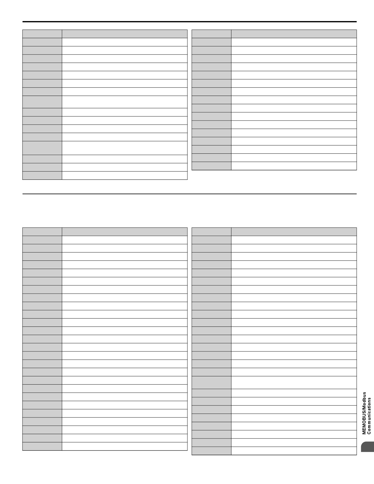
C.10 MEMOBUS/Modbus Data Table
Fault Code
Fault Name
Fault Code
Fault Name
0064H
Low Feedback (LFB)
008DH
Flash memory circuit exception (CPF12)
0065H
High Feedback (HFB)
008EH
Watchdog circuit exception (CPF13)
0066H
Setpoint Not Met (NMS)
008FH
Control Circuit Fault (CPF14)
0067H
Pump Over Cycle (POC)
0091H
Clock Fault (CPF16)
0069H
Net Master Lost (MSL)
0092H
Timing Fault (CPF17)
006BH
Anti-Jam Fault (AJF)
0093H
Control Circuit Fault (CPF18)
006DH
Wire Break (FDBKL)
0094H
Control Circuit Fault (CPF19)
0095H
Hardware fault at power up (CPF20)
0070H
Low Water Level (LWL)
0096H
Hardware fault at communication start up (CPF21)
0071H
High Water Level (HWL)
0097H
A/D Conversion Fault (CPF22)
0075H
Volute-Thermostat Fault (VLTS)
0098H
PWM Feedback Fault (CPF23)
0083H
A/D Conversion Error (CPF02)
0099H
Drive capacity signal fault (CPF24)
0084H
PWM Data Fault (CPF03)
0101H
Option compatibility error (oFA00)
Drive specification mismatch during Terminal Board or
0087H
0102H
Option not properly connected (oFA01)
Control Board replacement (CPF06)
0104H
Option Self-diagnostics Error (oFA03)
0088H
Terminal Board Communication Fault (CPF07)
0089H
EEPROM Serial Communication Fault (CPF08)
0105H
Option Flash Write Mode Error (oFA04)
008CH
RAM fault (CPF11)
<1> Available in drive software versions PRG: 1020 and later.
u Alarm Register Contents
The table below shows the alarm codes that can be read out from MEMOBUS/Modbus register 007FH.
Table C.5 Alarm Register 007FH Contents
Alarm Code
Fault Name
Alarm Code
Fault Name
0001H
Undervoltage (Uv)
0022H
Motor Overheat (oH3)
0002H
Overvoltage (ov)
002AH
Drive Disabled (dnE)
0003H
Heatsink Overheat (oH)
0031H
MECHATROLINK Watchdog Timer Error (E5)
0004H
Drive Overheat (oH2)
0032H
Station Address Setting Error (AEr)
0005H
Overtorque 1 (oL3)
0033H
MECHATROLINK Comm. Cycle Setting Error (CyC)
0006H
Overtorque 2 (oL4)
0034H
High Current Alarm (HCA)
0007H
Run commands input error (EF)
0039H
External Fault (input terminal S1) (EF1)
0008H
Drive Baseblock (bb)
003AH
External Fault (input terminal S2) (EF2)
0009HP
Pump Fault 3, input terminal S3 (EF3)
003BH
Safe Disable Input (HbbF)
000AH
Pump Fault 4, input terminal S4 (EF4)
003CH
Safe Disable Input (Hbb)
000BH
Pump Fault 5, input terminal S5 (EF5)
003DH
Mechanical Weakening Detection 1 (oL5)
000CH
Pump Fault 6, input terminal S6 (EF6)
003EH
Mechanical Weakening Detection 2 (UL5)
000DH
Pump Fault 7, input terminal S7 (EF7)
004CH
Loss of Prime (LOP)
000FH
Reserved
004EH
Underload Detection 6 (UL6)
0010H
Overspeed (oS)
0050H
AnalogFB Lost Switched to Net
0013H
Digital operator connection fault (oPr)
0051H
Waiting for Master (NETSCAN)
0014H
MEMOBUS/Modbus Communication Error (CE)
0052H
Pump Cycling Pump Over Cycle (PoC)
0015H
Option Communication Error (bUS)
0053H
Low Feedback Low FB Sensed
0016H
Serial Communication Transmission Error (CALL)
0054H
High Feedback High FB Sensed
0017H
Motor Overload (oL1)
0056H
Freq. Ref Pump Min (P1-06)
0018H
Drive Overload (oL2)
0057H
Freq. Ref Thrust (P4-12)
001AH
Option Card External Fault (EF0)
0058H
Low City Pressure
001DH
Serial Communication Transmission Error (CALL)
005CH
Feedback Loss Wire Break
001EH
Undertorque Detection 1 (UL3)
005EH
R-DNE-Sx Remote Drv Dis
001FH
Undertorque Detection 2 (UL4)
005FH
Low Suction Pressure
0020H
MEMOBUS/Modbus Test Mode Fault (SE)
C
0059H
Anti Jam Active
413
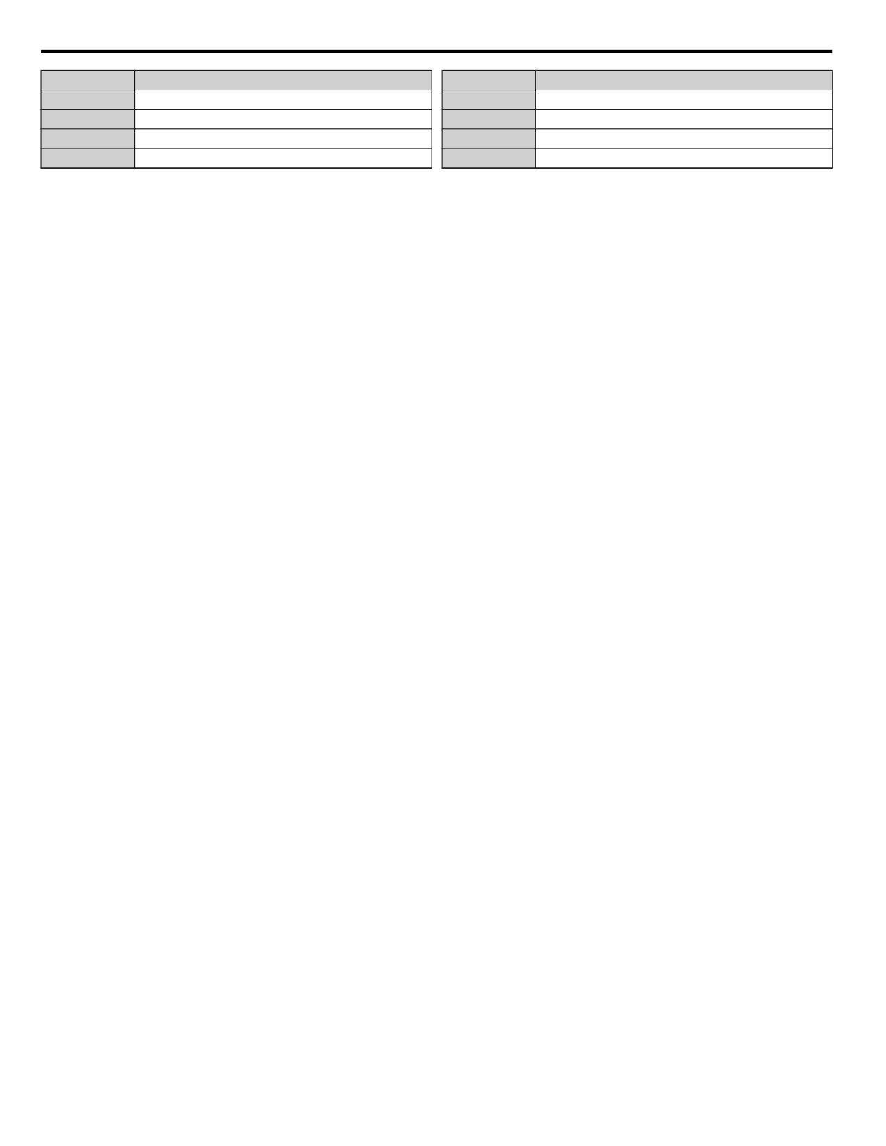
C.10 MEMOBUS/Modbus Data Table
Alarm Code
Fault Name
Alarm Code
Fault Name
0060H
Low Water In Tank
0066H
Setpoint Not Met (NMS)
0063H
Clock Not Set (TIM)
0067H
Emergency Override FWD (EoF)
0064H
HOA Battery Low (bAT)
0068H
Emergency Override REV (Eor)
0065H
HOA Time Deviation Error (TdE)
0069H
Feedback Loss Go To Freq b5-13
414
C.11 Enter Command
C.11 Enter Command
When writing parameters to the drive from the PLC using MEMOBUS/Modbus communication it depends on the setting of
parameter H5-11 if an Enter command must be used to enable these parameters or not. This sections explains Enter commands.
u Enter Command Types
The drive supports two types of Enter commands as shown in Table C.6. An Enter command is enabled by writing 0 to register
number 0900H or 0910H. These registers can be written to only. An error will occur if the user attempts to read from these
registers.
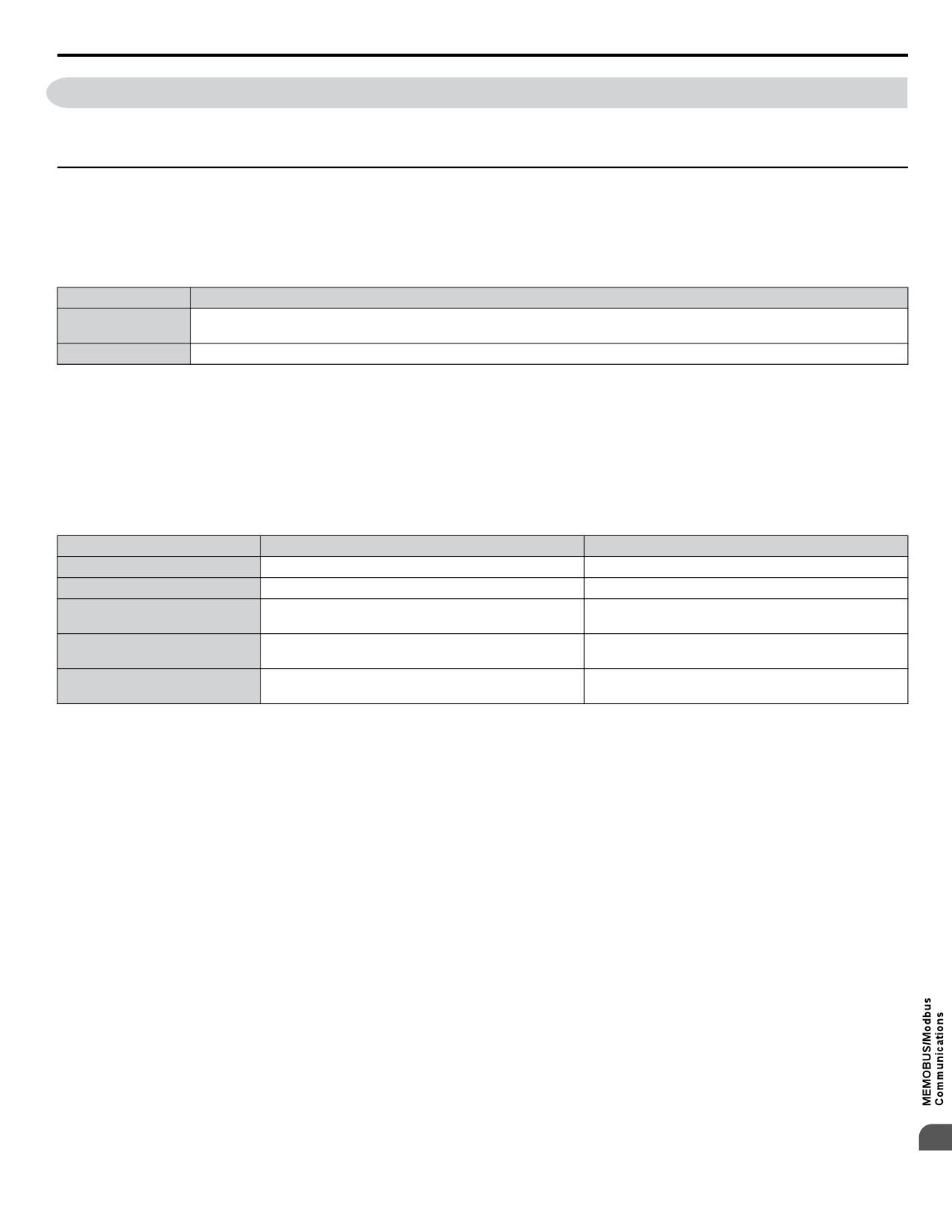
Table C.6 Enter Command Types
Register No.
Description
Writes data into the EEPROM (non-volatile memory) of the drive and enables the data in RAM at the same time. Parameter
0900H
changes remain even if the power supply is cycled.
0910H
Writes data in the RAM only. Parameter changes are lost when the drive is shut off.
Note:
1. Because the EEPROM can be written to a maximum of 100,000 times, refrain from writing to the EEPROM too often. The Enter
command registers are write-only. Consequently, if these registers are read, then the register address will be invalid (Error code: 02H).
An Enter command is not required if reference or broadcast data are sent to the drive.
2. Parameter data cannot be written to EEPROM during undervoltage, even using 0900H.
3. If undervoltage occurs when a making several parameter changes issued with a single ENTER command, the writing process may be
aborted before all of the new changes have been written. Because all of the data has not yet been written, the EEPROM data error
“CPF06” will be displayed the next time power to the drive is cycled. To prevent this problem, wait approximately 5 seconds after
issuing the ENTER command before shutting off drive power.
n H5-11 and the Enter Command
H5-11 Settings
H5-11 = 0
H5-11 = 1
Drive being replaced
G7, F7
V7
How parameter settings are enabled
When the Enter command is received from the master.
As soon as the value is changed.
Upper/lower limit check takes the settings of related
The upper/lower limit of the changed parameter is
Upper/lower limit check
parameters into account.
checked only.
Not affected. The settings of related parameters remain
The default settings of related parameters are changed
Default value of related parameters
unchanged. They must be changed manually if needed.
automatically.
Error handling when setting
Data is accepted even if one setting is invalid. The invalid
Error occurs if only one setting is invalid. All data sent
multiple parameters
setting will be discarded. No error message occurs.
are discarded.
C
415
C.12 Communication Errors
C.12 Communication Errors
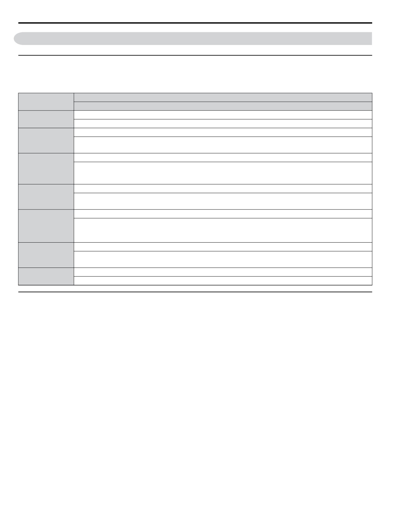
u MEMOBUS/Modbus Error Codes
A list of MEMOBUS/Modbus errors appears below.
When an error occurs, remove whatever caused the error and restart communications.
Error Name
Error Code
Cause
Function Code Error
01H
• Attempted to set a function code from a PLC other than 03H, 08H, and 10H.
Register Number Error
02H
• A register number specified in the command message does not exist.
• Attempted to send a broadcast message using other register numbers than 0001H or 0002H.
Bit Count Error
• Read data or write data is greater than 16 bits. Invalid command message quantity.
03H
• In a write message, the “Number of Data Items” contained within the message does not equal twice the amount of data words
(i.e., the total of Data 1+ Data 2, etc.).
Data Setting Error
21H
• Control data or parameter write data is outside the allowable setting range.
• Attempted to write a contradictory parameter setting.
Write Mode Error
• Attempted to write while the drive was operating to a parameter that cannot be written to during run.
22H
• During an EEPROM data error (CPF06), the master attempted to write to a parameter other than A1-00 to -05, E1-03, or o2-04.
• Attempted to write to read-only data.
DC Bus Undervoltage Write Error
23H
• Attempted to write from the master during an undervoltage fault (Uv1).
• Attempted to execute and Enter command during Uv1.
Write Error During Parameter Process
24H
• Master attempted writing to the drive while the drive was processing parameter data.
u Slave Not Responding
In the following situations, the slave drive will ignore the command message sent from the master, and not send a response
message:
• When a communications error (overrun, framing, parity or CRC-16) is detected in the command message.
• When the slave address in the command message and the slave address in the drive do not match (remember to set the slave
address for the drive using H5-01).
• When the gap between two blocks (8 bit) of a message exceeds 24 bits.
• When the command message data length is invalid.
Note:
If the slave address specified in the command message is 00H, all slaves execute the write function, but do not return response messages
to the master.
416
C.13 Self-Diagnostics
C.13 Self-Diagnostics
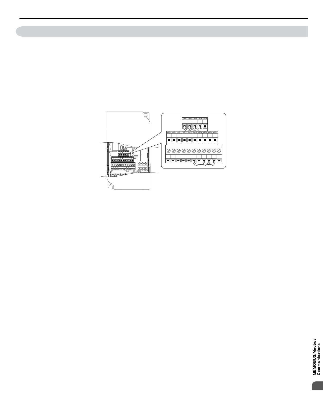
The drive has a built-in self-diagnosing function of the serial communication interface circuits. To perform the self-diagnosis
function, use the following procedure.
DANGER! Electrical Shock Hazard. Do not connect or disconnect wiring while the power is on. Failure to comply will result in death or
serious injury. Before servicing, disconnect all power to the equipment. The internal capacitor remains charged even after the power supply
is turned off. The charge indicator LED will extinguish when the DC bus voltage is below 50 Vdc. To prevent electric shock, wait at least
one minute after all indicators are OFF and measure the DC bus voltage level to confirm safe level.
1. Turn on the power to the drive.
2. Note the present terminal S6 function selection setting (H1-06) and set it for the communications test mode
(H1-06 = 67).
3. Turn off the power to the drive.
4. With the power off, wire the drive as shown in the following figure:
R+ R㸫 S+ S㸫 IG
P1
P2
PC A1
A2
+V AC AM AC MP
R+ R㸫 S+ S㸫 IG
S1
S2
S3
S4
S5
S6
S7
HC SC H1
RP
P1
P2
PC A1
A2
+V AC AM AC MP
S1
S2
S3
S4
S5
S6
S7
HC SC H1
RP
MA MB MC
Figure C.9 Terminal Connections for Communication Self-Diagnostics
5. Check and note the setting of DIP switch S3. Set it to NPN if it is in the PNP position.
6. Turn the power to the drive back on.
7. During normal operation, the drive will display PASS. This indicates that the communications test mode is operating
normally.
When a fault occurs, the drive will display “CE” on the keypad display.
8. Turn off the power supply.
9. Remove the wire jumpers from terminal R+, R-, S+, S- and, S6-SC and set back DIP switch S3 to its original position.
Set terminal S6 to its original function.
10.Return to normal operation.
C
417
Appendix: D
Standards Compliance
This chapter explains the guidelines and criteria for maintaining UL standards.
D.1
SECTION SAFETY
420
D.2
EUROPEAN STANDARDS
422
D.3
UL AND CSA STANDARDS
427
D.1
UL STANDARDS
435
419
D.1 Section Safety
D.1
Section Safety
DANGER
Electrical Shock Hazard
Do not connect or disconnect wiring while the power is on.
Failure to comply will result in death or serious injury.
WARNING
Electrical Shock Hazard
Do not operate equipment with covers removed.
Failure to comply could result in death or serious injury.
The diagrams in this section may show drives without covers or safety shields to show details. Be sure to reinstall covers or
shields before operating the drives and run the drives according to the instructions described in this manual.
Always ground the motor-side grounding terminal.
Improper equipment grounding could result in death or serious injury by contacting the motor case.
Do not touch any terminals before the capacitors have fully discharged.
Failure to comply could result in death or serious injury.
Before wiring terminals, disconnect all power to the equipment. The internal capacitor remains charged even after the power
supply is turned off. The charge indicator LED will extinguish when the DC bus voltage is below 50 Vdc. To prevent electric
shock, wait at least five minutes after all indicators are off and measure the DC bus voltage level to confirm safe level.
Do not allow unqualified personnel to perform work on the drive.
Failure to comply could result in death or serious injury.
Installation, maintenance, inspection, and servicing must be performed only by authorized personnel familiar with
installation, adjustment and maintenance of AC drives.
Do not perform work on the drive while wearing loose clothing, jewelry or without eye protection.
Failure to comply could result in death or serious injury.
Remove all metal objects such as watches and rings, secure loose clothing, and wear eye protection before beginning work
on the drive.
Do not remove covers or touch circuit boards while the power is on.
Failure to comply could result in death or serious injury.
Fire Hazard
Tighten all terminal screws to the specified tightening torque.
Loose electrical connections could result in death or serious injury by fire due to overheating of electrical connections.
Do not use an improper voltage source.
Failure to comply could result in death or serious injury by fire.
Verify that the rated voltage of the drive matches the voltage of the incoming power supply before applying power.
Do not use improper combustible materials.
Failure to comply could result in death or serious injury by fire.
Attach the drive to metal or other noncombustible material.
Install adequate branch circuit protection according to applicable local codes and this manual.
Failure to comply could result in fire and damage to the drive or injury to personnel. The device is suitable for use on a circuit
capable of delivering not more than 31,000 RMS symmetrical amperes, 240 Vac maximum (200 V class) and 480 Vac
maximum (400 V class) when protected by branch circuit protection devices specified in this manual.
420
D.1 Section Safety
NOTICE
Observe proper electrostatic discharge procedures (ESD) when handling the drive and circuit boards.
Failure to comply may result in ESD damage to the drive circuitry.
Never connect or disconnect the motor from the drive while the drive is outputting voltage.
Improper equipment sequencing could result in damage to the drive.
Do not use unshielded cable for control wiring.
Failure to comply may cause electrical interference resulting in poor system performance. Use shielded twisted-pair wires
and ground the shield to the ground terminal of the drive.
Do not allow unqualified personnel to use the product.
Failure to comply could result in damage to the drive or braking circuit.
Carefully review instruction manual TOBPC72060000 when connecting a braking option to the drive.
Do not modify the drive circuitry.
Failure to comply could result in damage to the drive and will void warranty.
Yaskawa is not responsible for modification of the product made by the user. This product must not be modified.
Check all the wiring to ensure that all connections are correct after installing the drive and connecting other devices.
Failure to comply could result in damage to the drive.
D
421
D.2 European Standards
D.2
European Standards
Figure D.1 CE Mark
The CE mark indicates compliance with European safety and environmental regulations and is required for engaging in business
and commerce in Europe.
European standards include the Machinery Directive for machine manufacturers, the Low Voltage Directive for electronics
manufacturers and the EMC guidelines for controlling noise.
This drive displays the CE mark based on the EMC guidelines and the Low Voltage Directive.
• Devices used in combination with this drive must also be CE certified and display the CE mark. When using drives displaying
the CE mark in combination with other devices, it is ultimately the responsibility of the user to ensure compliance with CE
standards. After setting up the device, verify that conditions meet European standards.
• Low Voltage Directive: 73/23/EEC, 93/68/EEC
u CE Low Voltage Directive Compliance
This drive has been tested according to European standard IEC/EN 61800-5-1, and it fully complies with the Low Voltage
Directive.
To comply with the Low Voltage Directive, be sure to meet the following conditions when combining this drive with other
devices:
n Area of Use
Do not use drives in areas with pollution higher than severity 2 and overvoltage category 3 in accordance with IEC/EN 664.
n Factory Recommended Branch Circuit Protection
Yaskawa recommends installing one of the following types of branch circuit protection to maintain compliance with UL508C.
Semiconductor protective type fuses are preferred. Alternate branch circuit protection devices are also listed in Table D.1.
NOTICE: If a fuse is blown or a Ground Fault Circuit Interrupter (GFCI) is tripped, check the wiring and the selection of peripheral devices
to identify the cause. Contact Yaskawa before restarting the drive or the peripheral devices if the cause cannot be identified.
Table D.1 Factory Recommended Drive Branch Circuit Protection
Fuse Type
Drive Model
Manufacturer: Bussmann
Model
Fuse Ampere Rating (A)
Single-Phase 200 V Class
BA0001
FWH-25A14F
25
BA0002
FWH-25A14F
25
BA0003
FWH-60B
60
BA0006
FWH-80B
80
BA0010
FWH-100B
100
Three-Phase 200 V Class
2A0001
FWH-25A14F
25
2A0002
FWH-25A14F
25
2A0004
FWH-25A14F
25
2A0006
FWH-25A14F
25
2A0010
FWH-70B
70
2A0012
FWH-70B
70
2A0020
FWH-90B
90
Three-Phase 400 V Class
4A0001
FWH-40B
40
4A0002
FWH-40B
40
422
D.2 European Standards
Fuse Type
Drive Model
Manufacturer: Bussmann
Model
Fuse Ampere Rating (A)
4A0004
FWH-50B
50
4A0005
FWH-70B
70
4A0007
FWH-70B
70
4A0009
FWH-90B
90
4A0011
FWH-90B
90
n Grounding
The drive is designed to be used in T-N (grounded neutral point) networks. If installing the drive in other types of grounded
systems, contact your dealer or Yaskawa for instructions.
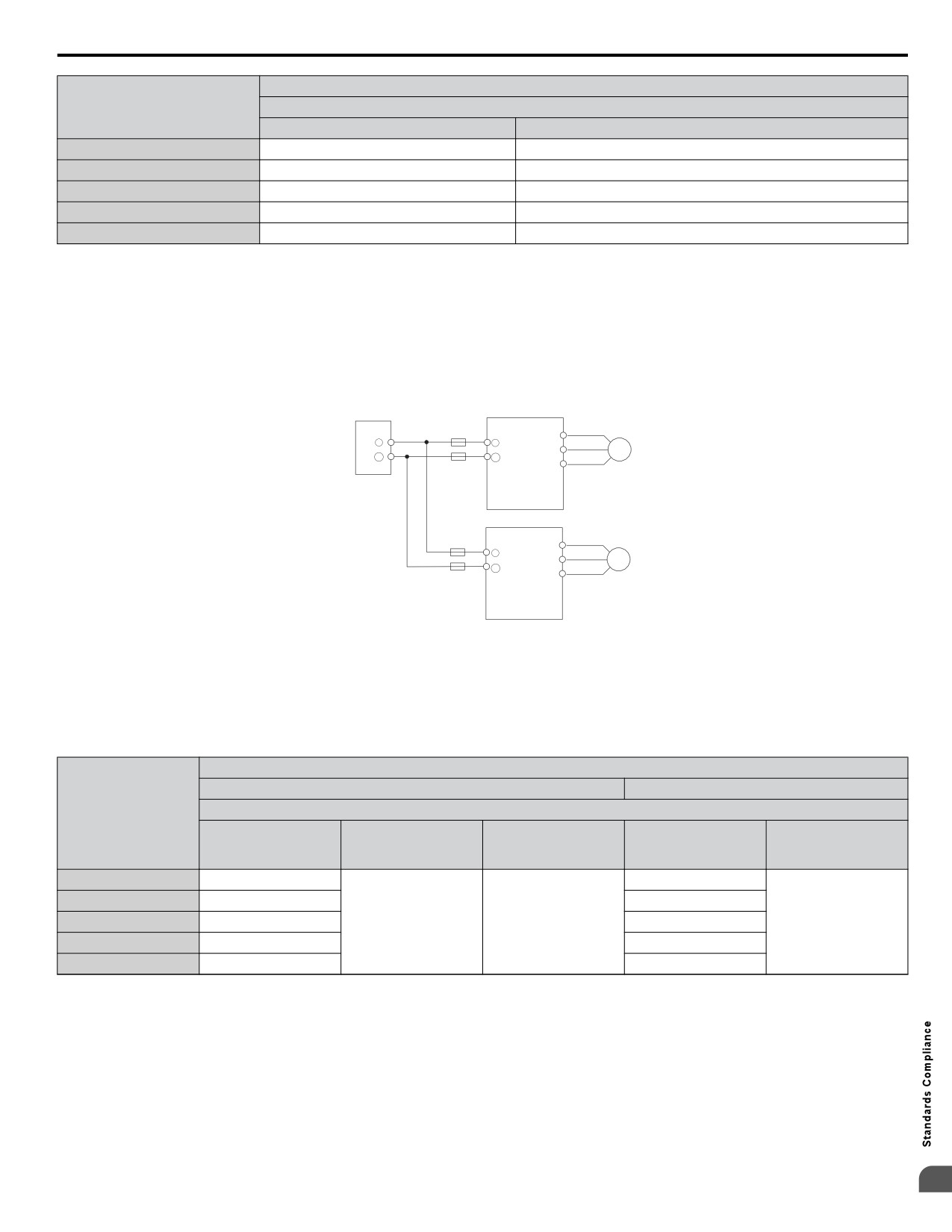
n CE Standards Compliance for DC Power Supply Input
Install the fuses in the following tables to meet CE standards.
DC power supply
(converter)
Fuse
U/ T1
+
+1
_
_
V/ T2
M
W/ T3
Drive
Fuse
U/ T1
+1
_
V/ T2
M
W/ T3
Drive
Figure D.2 Example of DC Power Supply Input (Two Drives Connected in Series)
Note:
1. When connecting multiple drives together, make sure that each drive has its own fuse. Replace all fuses when one fuse blows.
2. Refer to on page 40 for an AC power supply.
3. The recommended fuses and fuse holders are made by Fuji Electric.
Table D.2 Single-Phase 200 V Class Fuses and Fuse Holders
DC Power Supply Input
Fuse
Fuse Holder
Drive Model
Manufacturer: Fuji Electric
Rated Short Circuit
Type
Braking Current
Qty.
Type
Qty.
(kA)
BA0001
CR6L-20/UL
CMS-4
BA0002
CR6L-30/UL
CMS-4
BA0003
CR6L-50/UL
100
2
CMS-4
2
BA0006
CR6L-75/UL
CMS-5
BA0010
CR6L-100/UL
CMS-5
D
423
D.2
European Standards
Table D.3
Three-Phase 200 V Class Fuses and Fuse Holders
DC Power Supply Input
Fuse
Fuse Holder
Drive Model
Manufacturer: Fuji Electric
Rated Short Circuit
Type
Braking Current
Qty.
Type
Qty.
(kA)
2A0001
CR6L-20/UL
CMS-4
2A0002
CR6L-20/UL
CMS-4
2A0004
CR6L-20/UL
CMS-4
2A0006
CR6L-30/UL
100
2
CMS-4
2
2A0010
CR6L-50/UL
CMS-4
2A0012
CR6L-50/UL
CMS-4
2A0020
CR6L-75/UL
CMS-5
Table D.4
Three-Phase 400 V Class Fuses and Fuse Holders
DC Power Supply Input
Fuse
Fuse Holder
Drive Model
Manufacturer: Fuji Electric
Rated Short Circuit
Type
Braking Current
Qty.
Type
Qty.
(kA)
4A0001
CR6L-20/UL
CMS-4
4A0002
CR6L-20/UL
CMS-4
4A0004
CR6L-50/UL
CMS-4
4A0005
CR6L-50/UL
100
2
CMS-4
2
4A0007
CR6L-50/UL
CMS-4
4A0009
CR6L-50/UL
CMS-4
4A0011
CR6L-50/UL
CMS-4
n
Guarding Against Harmful Materials
When installing IP20/Open-Chassis enclosure drives, use an enclosure that prevents foreign material from entering the drive
from above or below.
u EMC Guidelines Compliance
This drive is tested according to European standards EN 61800-3:2004/A1:2012 and it complies with the EMC guidelines.
n EMC Filter Installation
The following conditions must be met to ensure continued compliance with guidelines. Refer to EMC Filters on page 425
for EMC filter selection.
Installation Method
Verify the following installation conditions to ensure that other devices and machinery used in combination with this drive
also comply with EMC guidelines.
1. Install an EMC noise filter to the input side specified by Yaskawa for compliance with European standards.
2. Place the drive and EMC noise filter in the same enclosure.
3. Use braided shield cable for the drive and motor wiring or run the wiring through a metal conduit.
4. Keep wiring as short as possible. Ground the shield on both the drive side and the motor side.
5. Ground the largest possible surface area of the shield to the metal conduit when using braided shield cable. Yaskawa
recommends using a cable clamp.
424
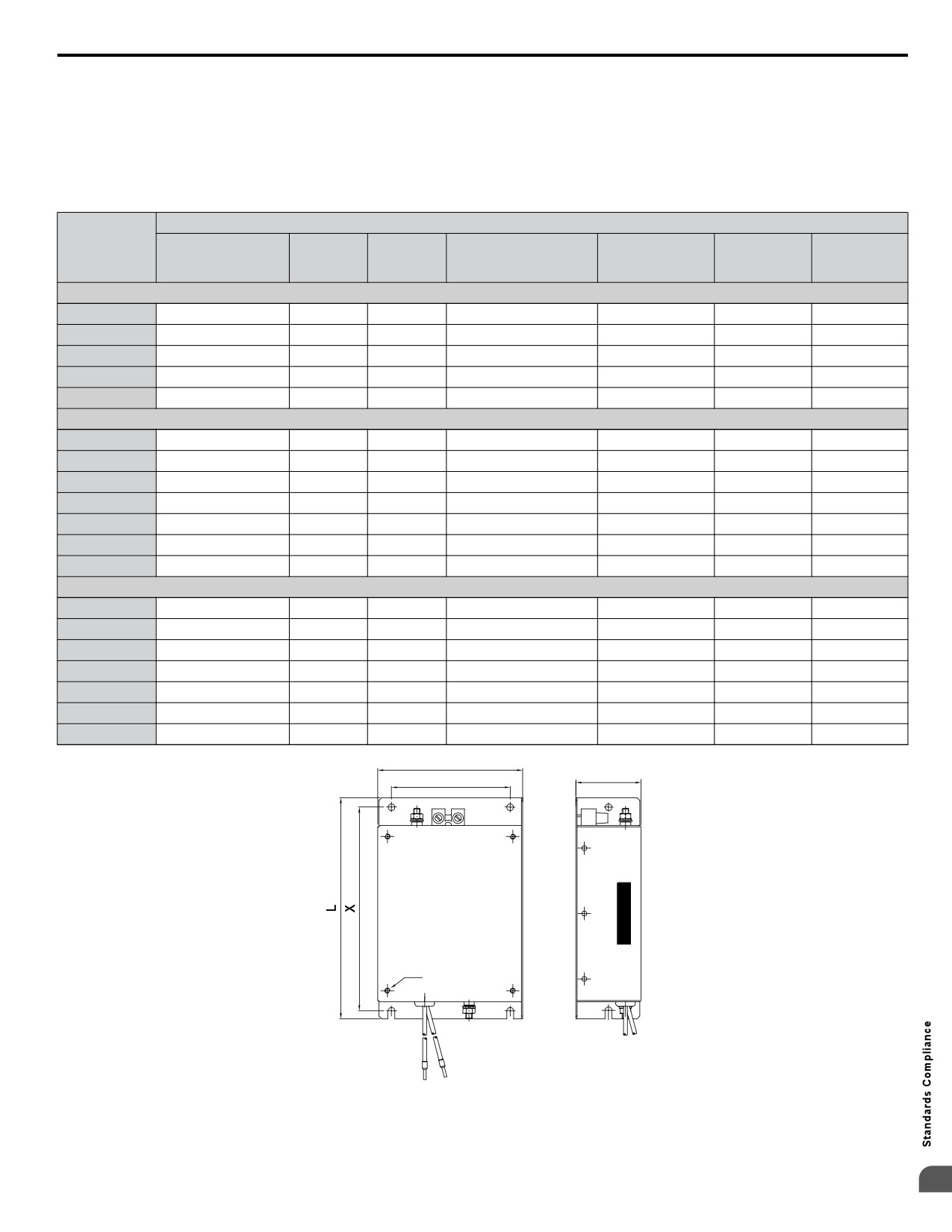
D.2 European Standards
Three-Phase 200 V / 400 V Class
Single-Phase 200 V Class
n EMC Filters
The drive should be installed with the EMC filters listed below in order to comply with the EN 61800-3:2004/A1:2012, category
C1 requirements.
Table D.5
EN 61800-3:2004/A1:2012 Category C1 Filters
Filter Data (Manufacturer: Schaffner)
Rated
Mounting
Drive
Filter
Weight
Dimensions
Type
Current
Dimensions
Mounting
Mounting
(lb)
[W x L x H] (in)
(A)
[Y x X] (in)
Screw A
Screw
200 V Class Single-Phase
BA0001
FS23638-10-07
10
0.97
2.8 x 6.7 x 1.8
2.0 x 6.1
M4
M5
BA0002
FS23638-10-07
10
0.97
2.8 x 6.7 x 1.8
2.0 x 6.1
M4
M5
BA0003
FS23638-10-07
10
0.97
2.8 x 6.7 x 1.8
2.0 x 6.1
M4
M5
BA0006
FS23638-20-07
20
1.65
4.4 x 6.7 x 2.0
3.6 x 6.1
M4
M5
BA0010
FS23638-20-07
20
1.65
4.4 x 6.7 x 2.0
3.6 x 6.1
M4
M5
200 V Three-Phase
2A0001
7.3
0.88
2.8 x 6.7 x 1.6
2.0 x 6.1
M4
M5
2A0002
7.3
0.88
2.8 x 6.7 x 1.6
2.0 x 6.1
M4
M5
2A0004
7.3
0.88
2.8 x 6.7 x 1.6
2.0 x 6.1
M4
M5
2A0006
7.3
0.88
2.8 x 6.7 x 1.6
2.0 x 6.1
M4
M5
2A0010
FS23637-14-07
14
1.28
4.4 x 6.7 x 1.8
3.6 x 6.1
M4
M5
2A0012
FS23637-14-07
14
1.28
4.4 x 6.7 x 1.8
3.6 x 6.1
M4
M5
2A0020
FS23637-24-07
24
1.98
5.7 x 6.9 x 2.0
4.7 x 6.1
M4
M5
400 V Class Three-Phase
4A0001
FS23639-5-07
5
1.10
4.4 x 6.7 x 1.8
3.6 x 6.1
M4
M5
4A0002
FS23639-5-07
5
1.10
4.4 x 6.7 x 1.8
3.6 x 6.1
M4
M5
4A0004
FS23639-5-07
5
1.10
4.4 x 6.7 x 1.8
3.6 x 6.1
M4
M5
4A0005
FS23639-10-07
10
1.54
4.4 x 6.7 x 1.8
3.6 x 6.1
M4
M5
4A0007
FS23639-10-07
10
1.54
4.4 x 6.7 x 1.8
3.6 x 6.1
M4
M5
4A0009
FS23639-10-07
10
1.54
4.4 x 6.7 x 1.8
3.6 x 6.1
M4
M5
4A0011
FS23639-15-07
15
1.98
5.7 x 6.9 x 2.0
4.7 x 6.3
M4
M5
W
H
Y
LINE
LOAD
A
PE
Figure D.3 EMC Filter Dimensions
D
425
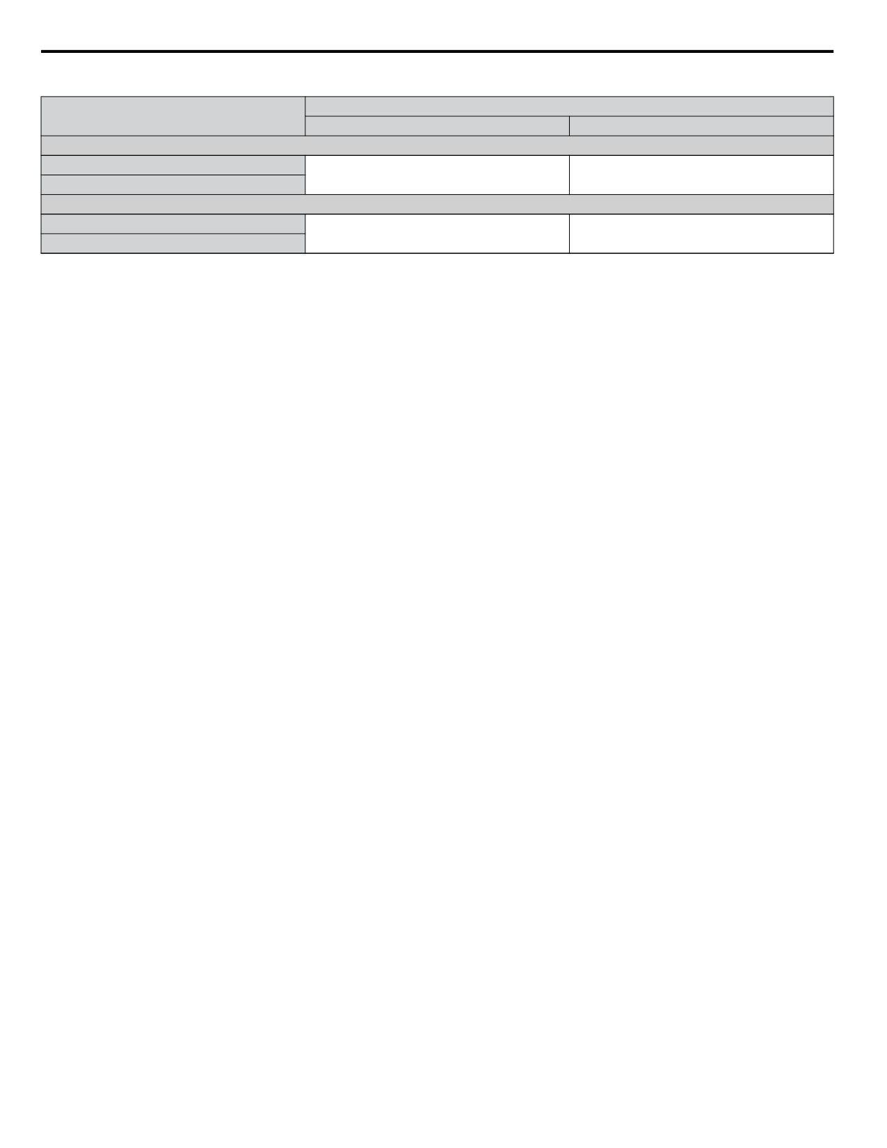
D.2 European Standards
n DC Link Chokes for IEC/EN 61000-3-2 Compliance
DC Link Choke
Drive Model
Model
Rating
200V Three-Phase Units
2A0004
5.4 A
UZDA-B
2A0006
8 mH
400 V Three-Phase Units
4A0002
3.2 A
UZDA-B
4A0004
28 mH
Note:
Models not listed in the above table do not require a DC link choke for EMC compliance.
426
D.3 UL and CSA Standards
D.3
UL and CSA Standards
u UL Standards Compliance
The UL/cUL mark applies to products in the United States and Canada and indicates that UL has performed product testing
and evaluation and determined that their stringent standards for product safety have been met. For a product to receive UL
certification, all components inside that product must also receive UL certification.
Figure D.4 UL/cUL Mark
This drive is tested in accordance with UL standard UL508C and complies with UL requirements. The following conditions
must be met to maintain compliance when using this drive in combination with other equipment:
n Installation Area
Do not install the drive to an area greater than pollution severity 2 (UL standard).
n Ambient Temperature
IP20/NEMA 1, UL Type 1 enclosure: -10 °C to +40 °C (14 °F to 104 °F)
IP20/IP00 Open-Chassis enclosure: -10 °C to +50 °C (14 °F to 122 °F)
n Main Circuit Terminal Wiring
Yaskawa recommends using closed-loop crimp terminals on all drive models. UL/cUL approval requires the use of UL Listed
closed-loop crimp terminals when wiring the drive main circuit terminals. Use only the tools recommended by the terminal
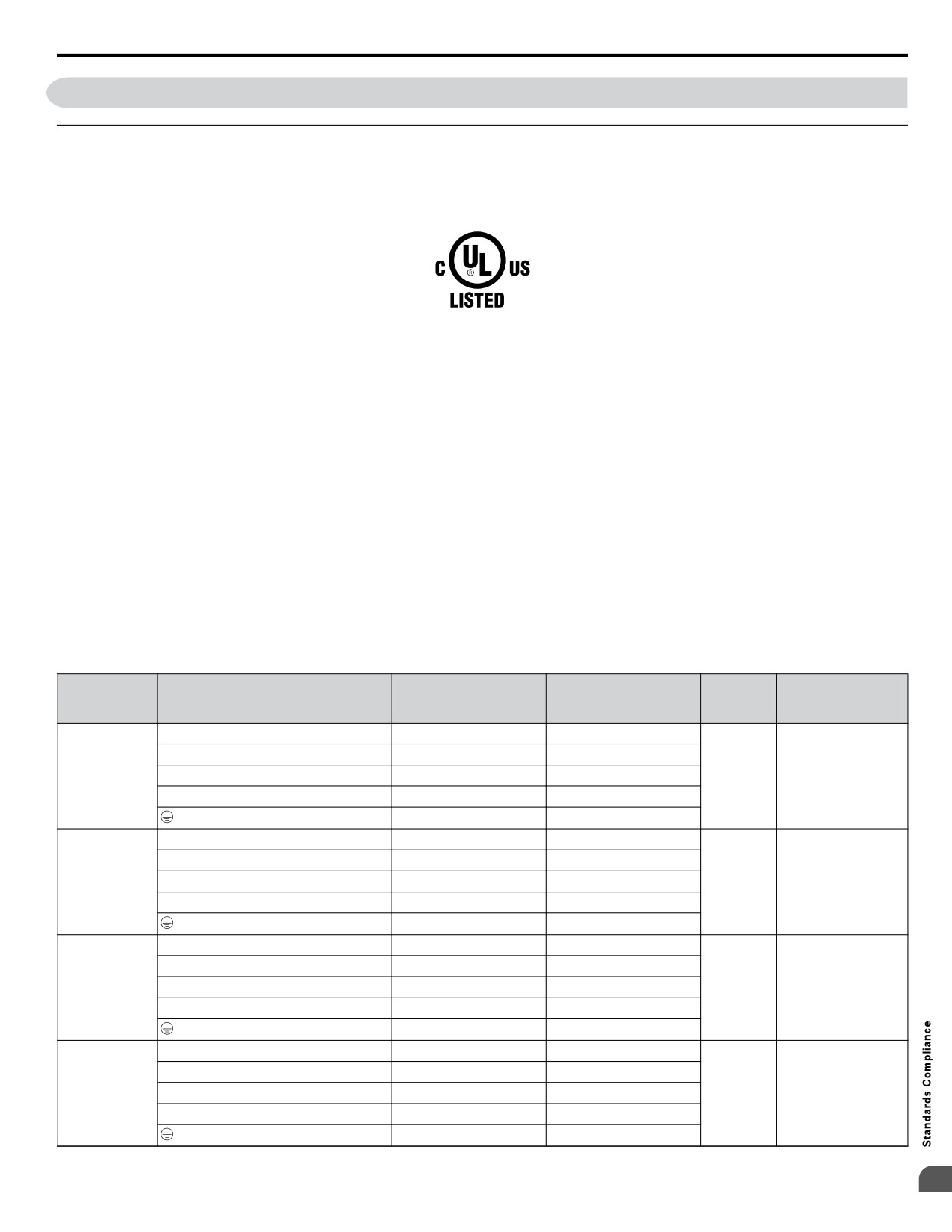
manufacturer for crimping. The wire gauges listed in Table D.6, Table D.7, and Table D.8 are Yaskawa recommendations.
Refer to local codes for proper wire gauge selections.
Table D.6
Wire Gauge and Torque Specifications
Recomm.
Tightening
Drive
Wire Range
Screw
Terminal
Gauge
Torque
Model
AWG, kcmil
Size
AWG, kcmil
N•m (lb.in.)
R/L1, S/L2, T/L3
14
18 to 14
U/T1, V/T2, W/T3
14
18 to 14
BA0001
0.8 to 1.0
BA0002
Ջ, Պ1, Պ2
-
18 to 14
M3.5
(7.1 to 8.9)
BA0003
B1, B2
-
18 to 14
14
18 to 14
R/L1, S/L2, T/L3
12
14 to 10
U/T1, V/T2, W/T3
14
14 to 10
1.2 to 1.5
BA0006
Ջ, Պ1, Պ2
-
14 to 10
M4
(10.6 to 13.3)
B1, B2
-
14 to 10
10
14 to 10
R/L1, S/L2, T/L3
10
14 to 10
U/T1, V/T2, W/T3
14
14 to 10
1.2 to 1.5
BA0010
Ջ, Պ1, Պ2
-
14 to 10
M4
(10.6 to 13.3)
B1, B2
-
14 to 10
10
14 to 10
R/L1, S/L2, T/L3
10
14 to 10
U/T1, V/T2, W/T3
14
14 to 10
2.3 to 2.5
BA0012
Ջ, Պ1, Պ2
-
14 to 10
M4
(20.4 to 22.1)
B1, B2
-
14 to 10
10
14 to 10
D
427
D.3 UL and CSA Standards
Recomm.
Tightening
Drive
Wire Range
Screw
Terminal
Gauge
Torque
Model
AWG, kcmil
Size
AWG, kcmil
N•m (lb.in.)
R/L1, S/L2, T/L3
8
12 to 8
U/T1, V/T2, W/T3
10
12 to 8
2.3 to 2.5
Ջ, Պ1, Պ2
-
12 to 8
(20.4 to 22.1)
BA0018
M5
B1, B2
-
12 to 8
2 to 2.5
8
12 to 8
(17.7 to 22.1)
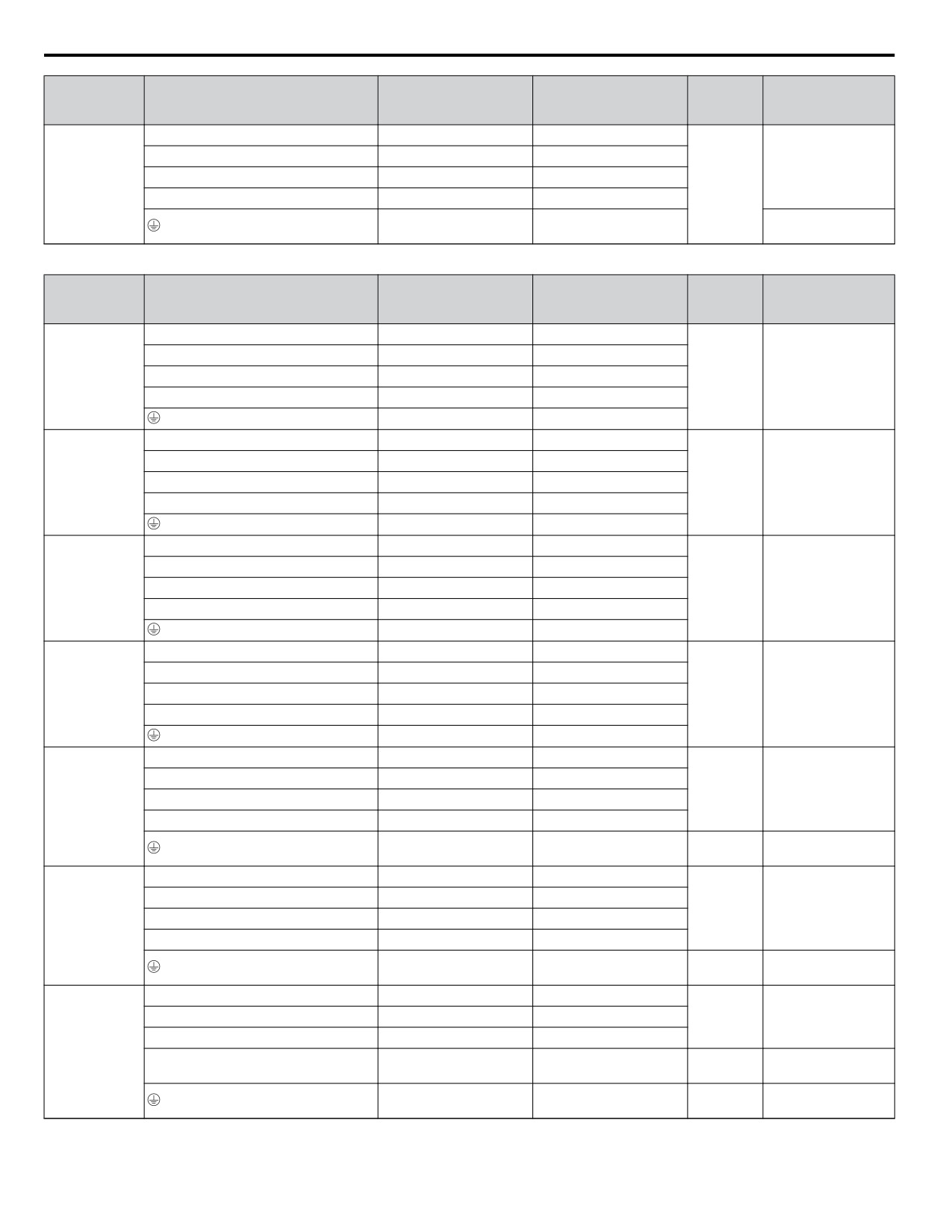
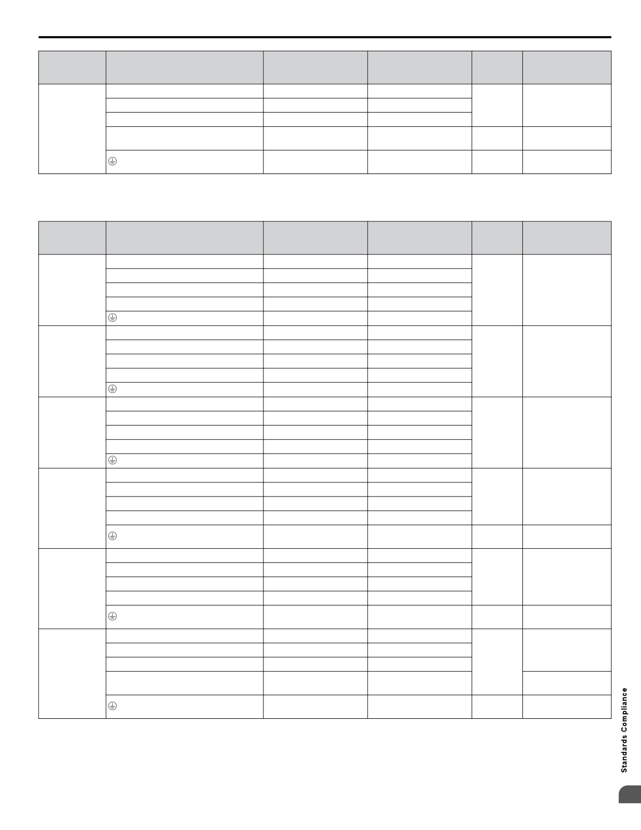
Table D.7
Wire Gauge and Torque Specifications
Recomm.
Tightening
Drive
Wire Range
Screw
Terminal
Gauge
Torque
Model
AWG, kcmil
Size
AWG, kcmil
N•m (lb.in.)
R/L1, S/L2, T/L3
14
18 to 14
2A0001
U/T1, V/T2, W/T3
14
18 to 14
2A0002
0.8 to 1.0
Ջ, Պ1, Պ2
-
18 to 14
M3.5
2A0004
(7.1 to 8.9)
2A0006
B1, B2
-
18 to 14
14
18 to 14
R/L1, S/L2, T/L3
12
14 to 10
U/T1, V/T2, W/T3
14
14 to 10
1.2 to 1.5
2A0010
Ջ, Պ1, Պ2
-
14 to 10
M4
(10.6 to 13.3)
B1, B2
-
14 to 10
10
14 to 10
R/L1, S/L2, T/L3
12
14 to 10
U/T1, V/T2, W/T3
14
14 to 10
1.2 to 1.5
2A0012
Ջ, Պ1, Պ2
-
14 to 10
M4
(10.6 to 13.3)
B1, B2
-
14 to 10
10
14 to 10
R/L1, S/L2, T/L3
10
14 to 10
U/T1, V/T2, W/T3
10
14 to 10
1.2 to 1.5
2A0020
Ջ, Պ1, Պ2
-
14 to 10
M4
(10.6 to 13.3)
B1, B2
-
14 to 10
10
14 to 10
R/L1, S/L2, T/L3
8
10 to 6
U/T1, V/T2, W/T3
8
10 to 6
2.1 to 2.3
M4
Ջ, Պ1, Պ2
-
10 to 6
(18.6 to 20.4)
2A0030
B1, B2
-
14 to 10
<1>
2 to 2.5
8
10 to 6
M5
(17.7 to 22.1)
R/L1, S/L2, T/L3
6
10 to 6
U/T1, V/T2, W/T3
8
10 to 6
2.1 to 2.3
M4
(18.6 to 20.4)
-, +1, +2
-
10 to 6
2A0040
B1, B2
-
14 to 10
2 to 2.5
6
10 to 6
M5
(17.7 to 22.1)
R/L1, S/L2, T/L3
4
6 to 4
5.4 to 6.0
U/T1, V/T2, W/T3
4
6 to 4
M6
(47.8 to 53.1)
Ջ, Պ1, Պ2
-
6 to 4
2A0056
2.7 to 3.0
B1, B2
-
10 to 6
M5
(23.9 to 26.6)
5.4 to 6.0
6
8 to 4
M6
(47.8 to 53.1)
428
D.3 UL and CSA Standards
Recomm.
Tightening
Drive
Wire Range
Screw
Terminal
Gauge
Torque
Model
AWG, kcmil
Size
AWG, kcmil
N•m (lb.in.)
R/L1, S/L2, T/L3
3
8 to 2
9.9 to 11
U/T1, V/T2, W/T3
3
8 to 2
M8
(87.6 to 97.4)
Ջ, Պ1, Պ2
-
8 to 2
2A0069
2.7 to 3.0
B1, B2
-
8 to 6
M5
(23.9 to 26.6)
5.4 to 6.0
6
6 to 4
M6
(47.8 to 53.1)
<1> When an EMC filter is installed, additional measures must be taken to comply with IEC/EN 61800-5-1. Refer to EMC Filter Installation on page
424 for details.
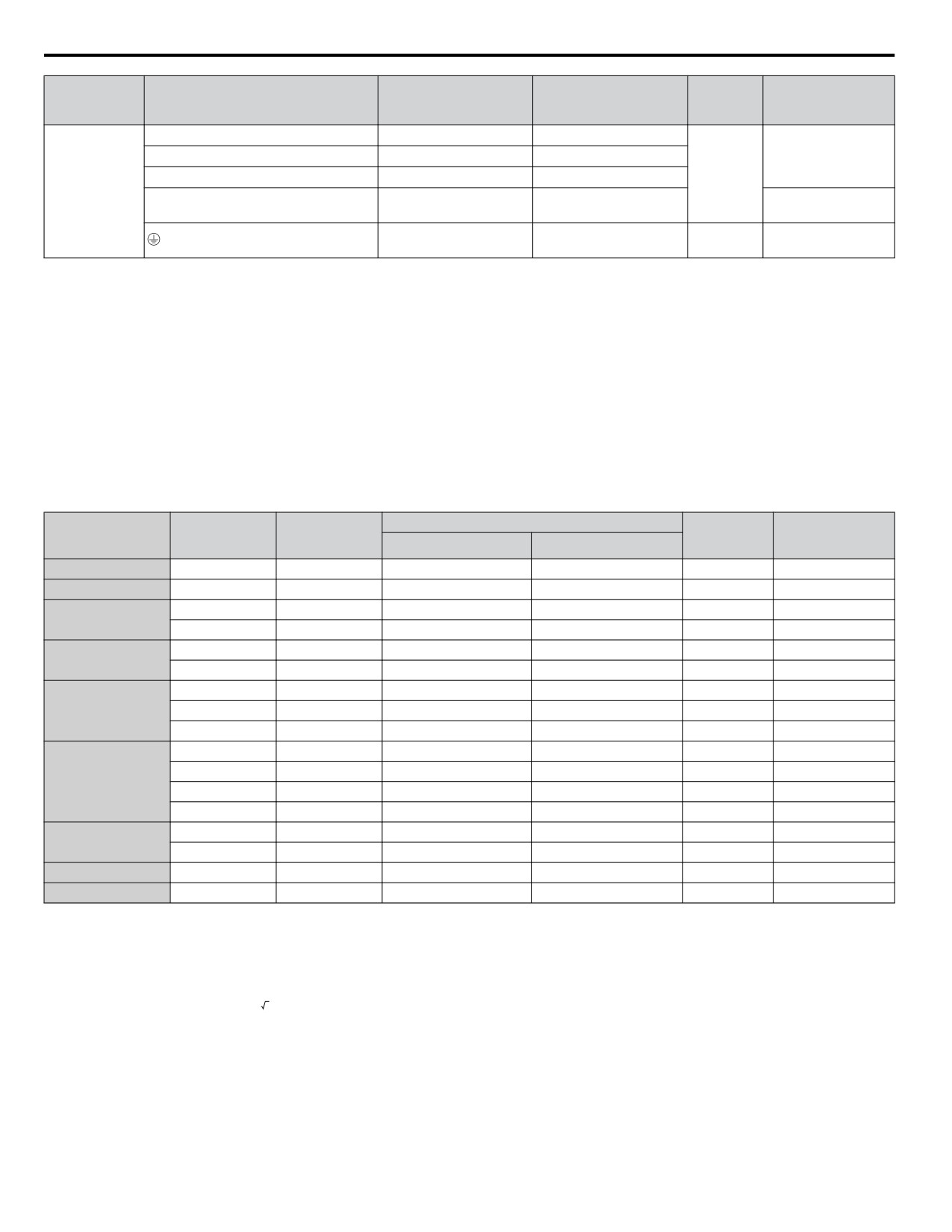
Table D.8
Wire Gauge and Torque Specifications
Recomm.
Tightening
Drive
Wire Range
Screw
Terminal
Gauge
Torque
Model
AWG, kcmil
Size
AWG, kcmil
N•m (lb.in.)
R/L1, S/L2, T/L3
14
14 to 10
U/T1, V/T2, W/T3
14
14 to 10
4A0001
1.2 to 1.5
4A0002
Ջ, Պ1, Պ2
-
14 to 10
M4
(10.6 to 13.3)
4A0004
B1, B2
-
14 to 10
14
14 to 10
R/L1, S/L2, T/L3
14
14 to 10
U/T1, V/T2, W/T3
14
14 to 10
4A0005
1.2 to 1.5
4A0007
Ջ, Պ1, Պ2
-
14 to 10
M4
(10.6 to 13.3)
4A0009
B1, B2
-
14 to 10
10
14 to 10
R/L1, S/L2, T/L3
12
14 to 10
U/T1, V/T2, W/T3
14
14 to 10
1.2 to 1.5
4A0011
Ջ, Պ1, Պ2
-
14 to 10
M4
(10.6 to 13.3)
B1, B2
-
14 to 10
10
14 to 10
R/L1, S/L2, T/L3
10
14 to 6
U/T1, V/T2, W/T3
10
14 to 6
2.1 to 2.3
M4
Ջ, Պ1, Պ2
-
14 to 6
(18.6 to 20.4)
4A0018
B1, B2
-
14 to 10
2 to 2.5
8
14 to 6
M5
(17.7 to 22.1)
R/L1, S/L2, T/L3
10
10 to 6
U/T1, V/T2, W/T3
10
10 to 6
2.1 to 2.3
M4
Ջ, Պ1, Պ2
-
10 to 6
(18.6 to 20.4)
4A0023
B1, B2
-
14 to 10
2 to 2.5
8
10 to 6
M5
(17.7 to 22.1)
R/L1, S/L2, T/L3
8
10 to 6
3.6 to 4.0
U/T1, V/T2, W/T3
8
10 to 6
(31.8 to 35.4)
Ջ, Պ1, Պ2
-
10 to 6
M5
4A0031
2.7 to 3.0
B1, B2
-
14 to 10
(23.9 to 26.6)
<1>
5.4 to 6.0
6
10 to 6
M6
(47.8 to 53.1)
D
429
D.3 UL and CSA Standards
Recomm.
Tightening
Drive
Wire Range
Screw
Terminal
Gauge
Torque
Model
AWG, kcmil
Size
AWG, kcmil
N•m (lb.in.)
R/L1, S/L2, T/L3
6
10 to 6
3.6 to 4.0
U/T1, V/T2, W/T3
8
10 to 6
(31.8 to 35.4)
Ջ, Պ1, Պ2
-
10 to 6
M5
4A0038
2.7 to 3.0
B1, B2
-
10 to 8
(23.9 to 26.6)
5.4 to 6.0
6
10 to 6
M6
(47.8 to 53.1)
<1> When an EMC filter is installed, additional measures must be taken to comply with IEC/EN 61800-5-1. Refer to EMC Filter Installation on page
424 for details.
Note:
Use crimp insulated terminals or insulated tubing for wiring these connections. Wires should have a continuous maximum allowable
temperature of 75 °C 600 V UL approved vinyl sheathed insulation. Ambient temperature should not exceed 30 °C.
Closed-Loop Crimp Terminal Recommendations
Yaskawa recommends crimp terminals made by JST and Tokyo DIP for the insulation cap.
Table D.9 matches the wire gauges and terminal screw sizes with Yaskawa-recommended crimp terminals, tools, and insulation
caps. Refer to the appropriate Wire Gauge and Torque Specifications table for the wire gauge and screw size for your drive
model. Place orders with a Yaskawa representative or the Yaskawa sales department.
The closed-loop crimp terminal sizes and values listed in Table D.9 are Yaskawa recommendations. Refer to local codes for
proper selections.
Table D.9 Closed-Loop Crimp Terminal Sizes
Tool
Insulation
Terminal
Crimp Terminal
Wire Gauge
Cap
Code <1>
Screws
Model Number
Machine No.
Die Jaw
Model No.
18 AWG
M3.5
R1.25-3.5
YA-4
AD-900
TP-003
100-066-217
16 AWG
M3.5
R1.25-3.5
YA-4
AD-900
TP-003
100-066-217
M3.5
R2-3.5
YA-4
AD-900
TP-003
100-066-218
14 AWG
M4
R2-4
YA-4
AD-900
TP-003
100-054-028
M4
R5.5-4
YA-4
AD-900
TP-005
100-054-029
12 / 10 AWG
M5
R5.5-5
YA-4
AD-900
TP-005
100-054-030
M4
8-4
YA-4
AD-901
TP-008
100-054-031
8 AWG
M5
R8-5
YA-4
AD-901
TP-008
100-054-032
M8
R8-8
YA-4
AD-901
TP-008
100-061-111
M4
14-4
YA-4
AD-902
TP-014
100-66-220
M5
R14-5
YA-4
AD-902
TP-014
100-054-034
6 AWG
M6
R14-6
YA-5
AD-952
TP-014
100-051-261
M8
R14-8
YA-5
AD-952
TP-014
100-054-035
M6
R22-6
YA-5
AD-953
TP-022
100-051-262
4 AWG
M8
R22-8
YA-5
AD-953
TP-022
100-051-263
3 AWG
M8
R38-8
YA-5
AD-954
TP-038
100-051-264
2 AWG
M8
R38-8
YA-5
AD-954
TP-038
100-051-264
<1> Codes refer to a set of three crimp terminals and three insulation caps. Prepare input and output wiring using two sets for each connection.
Example: Models with 14 AWG for both input and output require one set for input terminals and one set for output terminals, so the user should
order two sets of [100-066-218].
Note:
Consider the amount of voltage drop when selecting wire gauges. Increase the wire gauge when the voltage drop is greater than 2% of motor
rated voltage. Ensure the wire gauge is suitable for the terminal block. Use the following formula to calculate the amount of voltage drop:
Line drop voltage (V) =
3 × wire resistance (Ω/km) × wire length (m) × current (A) × 10-3
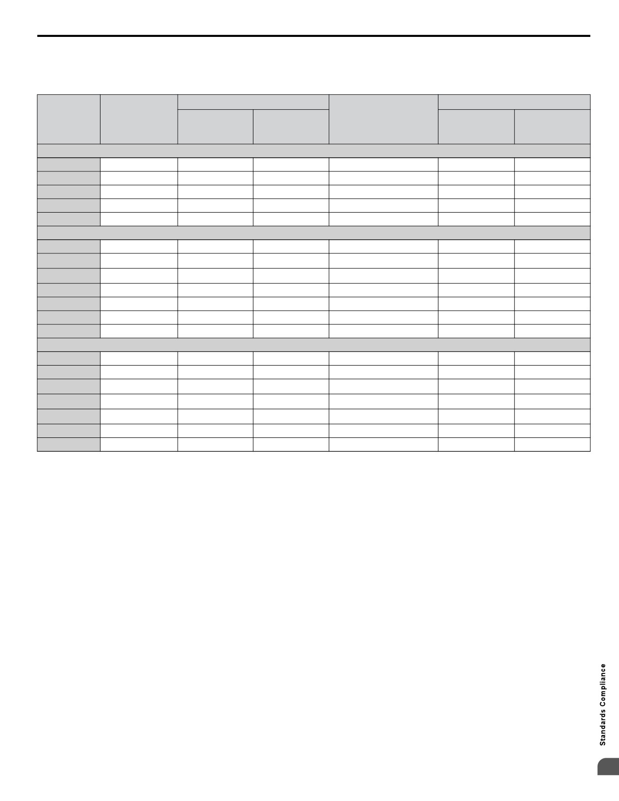
n Factory Recommended Branch Circuit Protection
Yaskawa recommends installing one of the following types of branch circuit protection to maintain compliance with UL508C.
Semiconductor protective type fuses are preferred.
Branch circuit protection shall be provided by any of the following according to Table D.10.
• Non-time Delay Class J, T, or CC fuses.
• Time Delay Class J, T, CC, or RK5 fuses.
430
D.3 UL and CSA Standards
• Semiconductor fuses.
• Molded Case Circuit Breakers (MCCB).
Table D.10 Factory Recommended Drive Branch Circuit Protection
Time Delay Fuses
MCCB
<5>
Bussmann
Non-time Delay
Semiconductor
Class J, T, or CC
Class RK5
Minimum
Drive Model
Fuse Rating (A)
Fuse Part Number
<1>
Fuse Rating (A)
Fuse Rating (A)
Rating (A)
Enclosure
<2>
<3>
(Fuse Ampere) <4>
Volume (in3)
200 V Class Single-Phase Drives
BA0001
6
3.5
4
FWH-25A14F (25)
15
600
BA0002
10
6
8
FWH-25A14F (25)
15
600
BA0003
20
10
15
FWH-60B (60)
15
600
BA0006
40
20
30
FWH-80B (80)
30
1152
BA0010
40
35
45
FWH-100B (100)
50
1152
200 V Class Three-Phase Drives
2A0001
3
1.5
2
FWH-25A14F (25)
15
600
2A0002
6 <6>
3
3
FWH-25A14F (25)
15
600
2A0004
15 <7>
6
8
FWH-25A14F (25)
15
600
2A0006
20
10
15
FWH-25A14F (25)
15
1152
2A0010
25
15
20
FWH-70B (70)
25
1152
2A0012
25
20
30
FWH-70B (70)
30
1152
2A0020
40
40
50
FWH-90B (90)
60
1152
400 V Class Three-Phase Drives
4A0001
3
2
2
FWH-40B (40)
15
1152
4A0002
6
3.5
3
FWH-40B (40)
15
1152
4A0004
15 <7>
7
8
FWH-50B (50)
15
1152
4A0005
20 <8>
10
10
FWH-70B (70)
15
1152
4A0007
25 <9>
12
15
FWH-70B (70)
20
1152
4A0009
25
15
20
FWH-90B (90)
20
1152
4A0011
30
20
30
FWH-90B (90)
35
1152
<1> Maximum 300% of drive input current rating for any Class J, T, or CC fuse except for models 2A0002, 2A0004, 4A0004, 4A0005, and 4A0007.
<2> Maximum 175% of drive input current rating for any Class J, T, or CC fuse.
<3> Maximum 225% of drive input current rating for any Class RK5 fuse.
<4> When using semiconductor fuses, Bussmann FWH are required for UL compliance.
<5> Maximum MCCB Rating is 15 A or 200% of drive input current rating, whichever is larger. MCCB voltage rating must be 600 Vac or greater.
Additionally, when using MCCBs for protection, the drive must be installed in a ventilated enclosure with minimum volume according the “Minimum
Enclosure Volume” column.
<6> Model 2A0002 requires Mersen (Ferraz) part number A6T6 for compliance.
<7> Models 2A0004 and 4A0004 require Mersen (Ferraz) part number A6T15 for compliance.
<8> Model 4A0005 requires Mersen (Ferraz) part number A6T20 for compliance.
<9> Model 4A0007 requires Mersen (Ferraz) part number A6T25 for compliance.
n Low Voltage Wiring for Control Circuit Terminals
Wire low voltage wires with NEC Class 1 circuit conductors. Refer to national state or local codes for wiring. The external
power supply shall be a UL-Listed Class 2 power source or equivalent.
n Drive Short-Circuit Rating
This drive has undergone the UL short-circuit test, which certifies that during a short circuit in the power supply the current
flow will not rise above 31,000 amps maximum at 240 V for 200 V class drives and 480 V for 400 V class drives.
• The MCCB and breaker protection and fuse ratings shall be equal to or greater than the short-circuit tolerance of the power
supply being used.
• Suitable for use on a circuit capable of delivering not more than 31,000 RMS symmetrical amperes for 240 V in 200 V class
drives (up to 480 V for 400 V class drives) motor overload protection.
D
431
D.3 UL and CSA Standards
u CSA Standards Compliance
Figure D.5 CSA Mark
n CSA for Industrial Control Equipment
The drive is CSA-certified as Industrial Control Equipment Class 3211.
Specifically, the drive is certified to: CAN/CSA C22.2 No. 04-04 and CAN/CSA C22.2 No.14-05.
u Drive Motor Overload Protection
Set parameter E2-01 (motor rated current) to the appropriate value to enable motor overload protection. The internal motor
overload protection is UL listed and in accordance with the NEC and CEC.
n E2-01: Motor Rated Current
Setting Range: Model Dependent
Default Setting: Model Dependent
Parameter E2-01 (motor rated current) protects the motor if parameter L1-01 is not set to 0 (default is 1, standard induction
motor protection enabled).
n L1-01: Motor Overload Protection Selection
The drive has an electronic overload protection function (oL1) based on time, output current and output frequency, which
protects the motor from overheating. The electronic thermal overload function is UL-recognized, so it does not require an
external thermal overload relay for single motor operation.
This parameter selects the motor overload curve used according to the type of motor applied.
Disable the electronic overload protection (L1-01 = 0: Disabled) and wire each motor with its own motor thermal overload
when connecting the drive to more than one motor for simultaneous operation.
Enable the motor overload protection (L1-01 = “1”, “2”, or “3”) when connecting the drive to a single motor unless there is
another means of preventing motor thermal overload. The electronic thermal overload function causes an oL1 fault, which
shuts off the output of the drive and prevents additional overheating of the motor. The motor temperature is continually
calculated as long as the drive is powered up.
n L1-02: Motor Overload Protection Time
Setting Range: 0.1 to 5.0 Minutes
Factory Default: 1.0 Minutes
The L1-02 parameter sets the allowed operation time before the oL1 fault occurs when the drive is running at 60 Hz and 150%
of the full load amp rating (E2-01) of the motor. Adjusting the value of L1-02 can shift the set of oL1 curves up the Y-axis of
the diagram below but will not change the shape of the curves.
432
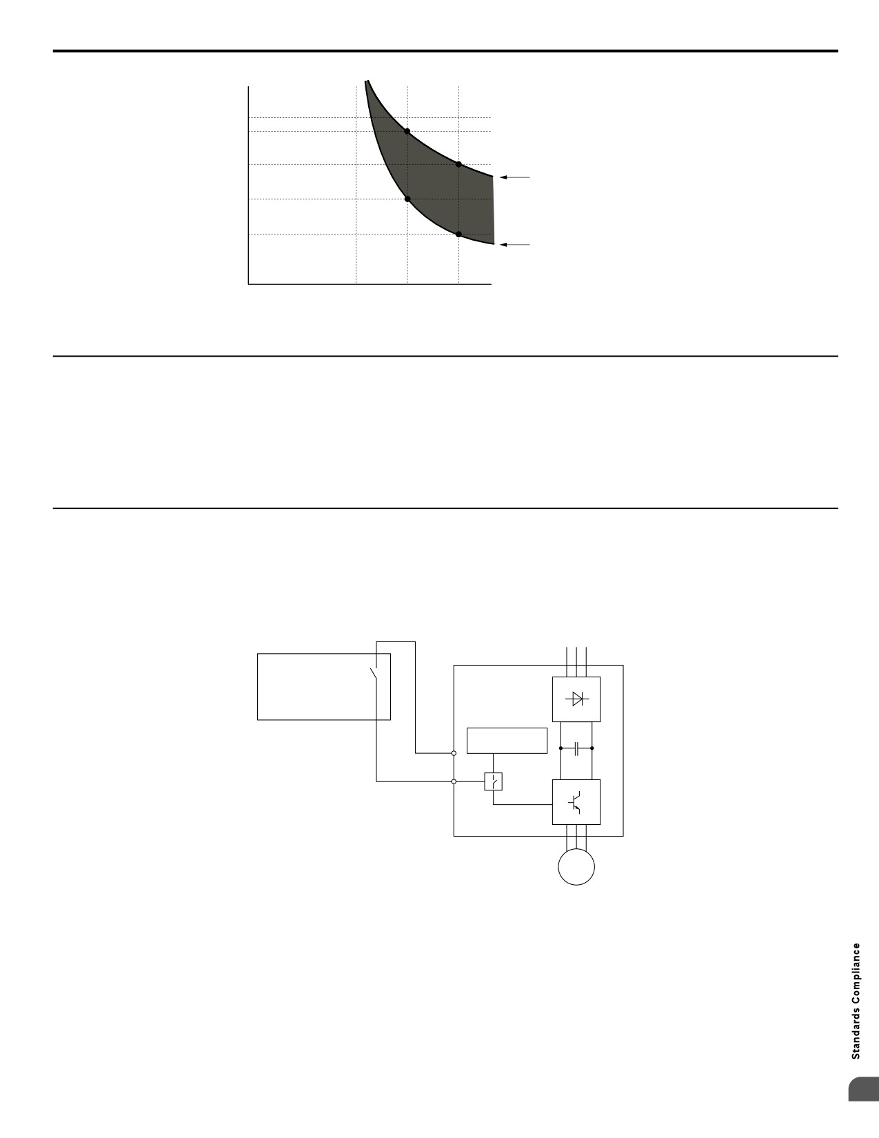
D.3 UL and CSA Standards
Operation time (minutes)
10
7
3
Cold start
(characteristics when an
overload occurs at a
1
complete stop)
Hot start
0.4
(characteristics when an
overload occurs during
continuous operation at 100%)
0.1
Motor current (%)
0
100
150
200
E2-01 = 100% motor current
Figure D.6 Motor Overload Protection Time
u Safe Disable Function Description
The Safe Disable function can be utilized to perform a safe stop according to the IEC/EN 61800-5-2, stop category 0
(Uncontrolled stop by power removal). It is designed to meet the requirements of the ISO/EN 13849-1, Safety Category 3, PL
d, and IEC/EN 61508, SIL2.
Removing the voltage from terminal H1 disables the drive output, i.e. the power supply to the motor is cut by stopping the
switching of the output transistors in a safe way. “Hbb” is shown on the display. Safe Disable is applicable for induction and
permanent magnet motors.
u Installation
If the Safe Disable function is utilized, the wire link between the terminals HC and H1 that is installed at shipment must be
removed entirely.
Connect the drive to an ISO/EN 13849-1, Safety Category 3 interrupting device so that in case of a Safe Disable request the
connection between the terminals HC and H1 is opened.
Power Supply
Drive
ISO/EN 13849-1 Safety
Cat, 3 Device
Controller
HC
H1
M
Figure D.7 Safe Disable Wiring Example
n Installation Precautions
• To ensure the Safe Disable function appropriately fulfills the safety requirements of the application, a thorough risk
assessment for the safety system must be carried out.
• The drive must be installed in an enclosure with a protection degree of at least IP54 in order to maintain ISO/EN 13849-1,
safety category 3 compliance.
• If the safety device and the drive are installed in separate cabinets, install the Safe Disable wires in a manner preventing
short circuits.
D
433
D.3 UL and CSA Standards
• The Safe Disable function does not cut the power supply to the drive and does not provide electrical isolation. Before any
installation or maintenance work is done, the power supply of the drive must be switched off.
• Consider the following when using PM motors: When the Safe Disable function is active, a failure in two of the drive power
devices can occur and current will continue to flow through the motor winding. This failure will not produce torque in an
induction motor, however, when occurring in a PM motor, torque will be produced and cause an alignment of the rotor
magnets, which may cause the rotor to turn up to 180 degrees electrically. Ensure that this possible failure mode is not safety-
critical for the application.
• The wiring distance for the Safe Disable inputs should not exceed 30 m.
• The time from opening the Safe Disable input until the drive output is switched off is less than 1 ms.
434
D.1 UL Standards
D.1
UL Standards
u UL Standards Compliance
The UL/cUL mark applies to products in the United States and Canada and indicates that UL has performed product testing
and evaluation and determined that their stringent standards for product safety have been met. For a product to receive UL
certification, all components inside that product must also receive UL certification.
Figure D.8 UL/cUL Mark
This drive is tested in accordance with UL standard UL508C and complies with UL requirements. The following conditions
must be met to maintain compliance when using this drive in combination with other equipment:
n Installation Area
Do not install the drive to an area greater than pollution severity 2 (UL standard).
n Ambient Temperature
IP20/NEMA 1, UL Type 1 enclosure: -10 °C to +40 °C (14 °F to 104 °F)
NEMA 4X, UL Type 4X/IP66 enclosure: -10 °C to +40 °C (14 °F to 104 °F)
u IP66/NEMA 4X, UL Type 4X Conditions of Acceptability
Adhere to the installation conditions specified in this manual to take full advantage of the IP66/NEMA 4X, UL Type 4X design
of this drive.
n Resistance Against Chemicals and Solvents
Table D.11 lists the information on chemical and solvent tolerability of the drive. The drive enclosure meets these requirements:
• UL50E: Enclosures for Electrical Equipment, Environmental Considerations NEMA 4X, UL Type 4X
• International Standard IEC 60529 Degrees of protection provided by enclosures (IP Code) IP66
Refer to the appropriate enclosure specification for more details on the enclosures resistance to chemicals and solvents.
Table D.11 Chemical and Solvent Tolerability
Reagent
Solvent
• Hydrochloric acid (10%)
• Sulfuric acid (10%)
• Methanol
• Nitric acid (10%)
• Ethanol
• Ammonia water
• Sodium chloride
NOTICE: Do not allow a stream of chemicals or solvents to be sprayed directly onto the drive enclosure. Failure to do so can damage the
drive.
NOTICE: Prevent moisture and other solvents from entering the drive enclosure when removing the front cover. Failing to do so can damage
the drive or considerably shorten its expected performance life.
u Main Circuit Terminal Wiring
Yaskawa recommends using closed-loop crimp terminals on all drive models. UL/cUL approval requires the use of UL Listed
closed-loop crimp terminals when wiring the drive main circuit terminals. Use only the tools recommended by the terminal
manufacturer for crimping. The wire gauges listed below are Yaskawa recommendations. Refer to local codes for proper wire
gauge selections.
D
435
D.1 UL Standards
n
Single-Phase 200 V Class
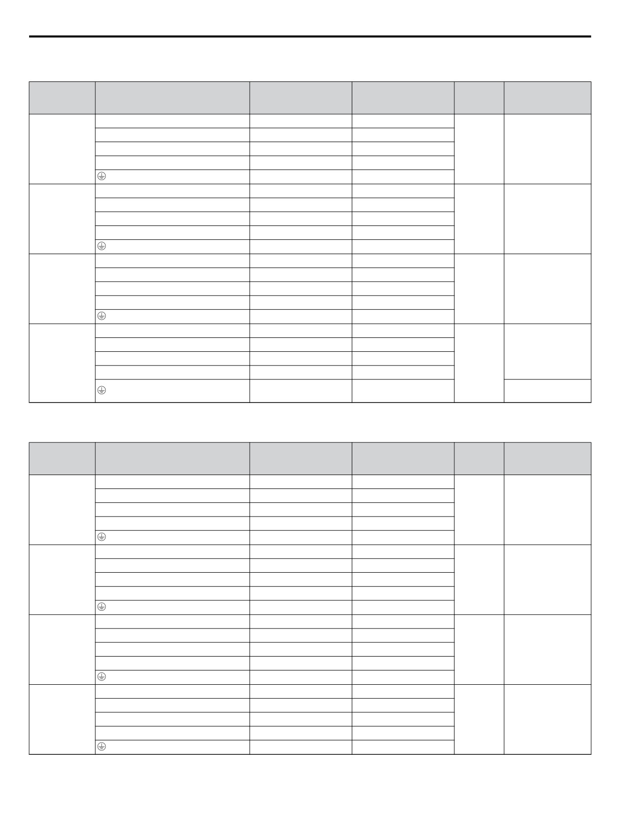
Table D.12
Wire Gauge and Torque Specifications
Recomm.
Tightening
Drive
Wire Range
Screw
Terminal
Gauge
Torque
Model
AWG, kcmil
Size
AWG, kcmil
N•m (lb.in.)
R/L1, S/L2, T/L3
12
14 to 10
U/T1, V/T2, W/T3
14
14 to 10
1.2 to 1.5
BV0006
Ջ, Պ1, Պ2
-
14 to 10
M4
(10.6 to 13.3)
B1, B2
-
14 to 10
10
14 to 10
R/L1, S/L2, T/L3
10
14 to 10
U/T1, V/T2, W/T3
14
14 to 10
1.2 to 1.5
BV0010
Ջ, Պ1, Պ2
-
14 to 10
M4
(10.6 to 13.3)
B1, B2
-
14 to 10
10
14 to 10
R/L1, S/L2, T/L3
10
14 to 10
U/T1, V/T2, W/T3
14
14 to 10
2.3 to 2.5
BV0012
Ջ, Պ1, Պ2
-
14 to 10
M4
(20.4 to 22.1)
B1, B2
-
14 to 10
10
14 to 10
R/L1, S/L2, T/L3
8
12 to 8
U/T1, V/T2, W/T3
10
12 to 8
2.3 to 2.5
Ջ, Պ1, Պ2
-
12 to 8
(20.4 to 22.1)
BV0018
M5
B1, B2
-
12 to 8
2 to 2.5
8
12 to 8
(17.7 to 22.1)
n
Three-Phase 200 V Class
Table D.13
Wire Gauge and Torque Specifications
Recomm.
Tightening
Drive
Wire Range
Screw
Terminal
Gauge
Torque
Model
AWG, kcmil
Size
AWG, kcmil
N•m (lb.in.)
R/L1, S/L2, T/L3
14
18 to 14
U/T1, V/T2, W/T3
14
18 to 14
0.8 to 1.0
2V0006
Ջ, Պ1, Պ2
-
18 to 14
M3.5
(7.1 to 8.9)
B1, B2
-
18 to 14
14
18 to 14
R/L1, S/L2, T/L3
12
14 to 10
U/T1, V/T2, W/T3
14
14 to 10
1.2 to 1.5
2V0010
Ջ, Պ1, Պ2
-
14 to 10
M4
(10.6 to 13.3)
B1, B2
-
14 to 10
10
14 to 10
R/L1, S/L2, T/L3
12
14 to 10
U/T1, V/T2, W/T3
14
14 to 10
1.2 to 1.5
2V0012
Ջ, Պ1, Պ2
-
14 to 10
M4
(10.6 to 13.3)
B1, B2
-
14 to 10
10
14 to 10
R/L1, S/L2, T/L3
10
14 to 10
U/T1, V/T2, W/T3
10
14 to 10
1.2 to 1.5
2V0020
Ջ, Պ1, Պ2
-
14 to 10
M4
(10.6 to 13.3)
B1, B2
-
14 to 10
10
14 to 10
436
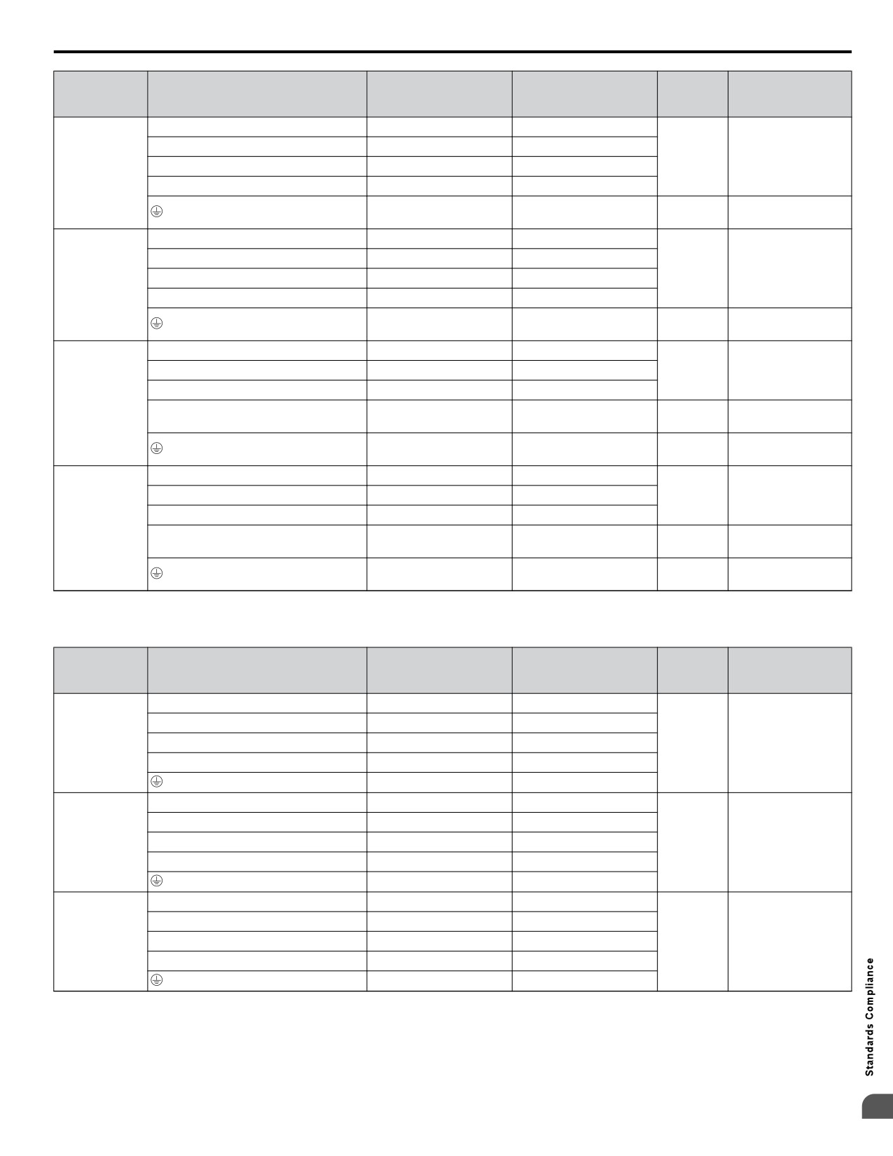
D.1
UL Standards
Recomm.
Tightening
Drive
Wire Range
Screw
Terminal
Gauge
Torque
Model
AWG, kcmil
Size
AWG, kcmil
N•m (lb.in.)
R/L1, S/L2, T/L3
8
10 to 6
U/T1, V/T2, W/T3
8
10 to 6
2.1 to 2.3
M4
Ջ, Պ1, Պ2
-
10 to 6
(18.6 to 20.4)
2V0030
B1, B2
-
14 to 10
2 to 2.5
8
10 to 6
M5
(17.7 to 22.1)
R/L1, S/L2, T/L3
6
10 to 6
U/T1, V/T2, W/T3
8
10 to 6
2.1 to 2.3
M4
Ջ, Պ1, Պ2
-
10 to 6
(18.6 to 20.4)
2V0040
B1, B2
-
14 to 10
2 to 2.5
6
10 to 6
M5
(17.7 to 22.1)
R/L1, S/L2, T/L3
4
6 to 4
5.4 to 6.0
U/T1, V/T2, W/T3
4
6 to 4
M6
(47.8 to 53.1)
Ջ, Պ1, Պ2
-
6 to 4
2V0056
2.7 to 3.0
B1, B2
-
10 to 6
M5
(23.9 to 26.6)
5.4 to 6.0
6
8 to 4
M6
(47.8 to 53.1)
R/L1, S/L2, T/L3
3
8 to 2
9.9 to 11
U/T1, V/T2, W/T3
3
8 to 2
M8
(87.6 to 97.4)
Ջ, Պ1, Պ2
-
8 to 2
2V0069
2.7 to 3.0
B1, B2
-
8 to 6
M5
(23.9 to 26.6)
5.4 to 6.0
6
6 to 4
M6
(47.8 to 53.1)
n
Three-Phase 400 V Class
Table D.14
Wire Gauge and Torque Specifications
Recomm.
Tightening
Drive
Wire Range
Screw
Terminal
Gauge
Torque
Model
AWG, kcmil
Size
AWG, kcmil
N•m (lb.in.)
R/L1, S/L2, T/L3
14
14 to 10
U/T1, V/T2, W/T3
14
14 to 10
4V0002
1.2 to 1.5
Ջ, Պ1, Պ2
-
14 to 10
M4
4V0004
(10.6 to 13.3)
B1, B2
-
14 to 10
14
14 to 10
R/L1, S/L2, T/L3
14
14 to 10
U/T1, V/T2, W/T3
14
14 to 10
4V0005
1.2 to 1.5
4V0007
Ջ, Պ1, Պ2
-
14 to 10
M4
(10.6 to 13.3)
4V0009
B1, B2
-
14 to 10
10
14 to 10
R/L1, S/L2, T/L3
12
14 to 10
U/T1, V/T2, W/T3
14
14 to 10
1.2 to 1.5
4V0011
Ջ, Պ1, Պ2
-
14 to 10
M4
(10.6 to 13.3)
B1, B2
-
14 to 10
10
14 to 10
D
437
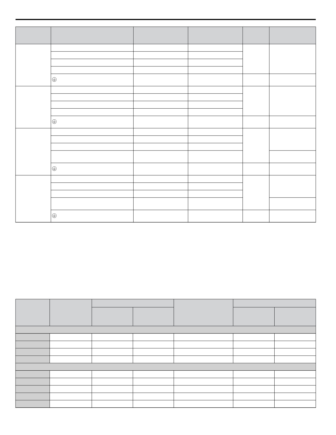
D.1 UL Standards
Recomm.
Tightening
Drive
Wire Range
Screw
Terminal
Gauge
Torque
Model
AWG, kcmil
Size
AWG, kcmil
N•m (lb.in.)
R/L1, S/L2, T/L3
10
14 to 6
U/T1, V/T2, W/T3
10
14 to 6
2.1 to 2.3
M4
Ջ, Պ1, Պ2
-
14 to 6
(18.6 to 20.4)
4V0018
B1, B2
-
14 to 10
2 to 2.5
8
14 to 6
M5
(17.7 to 22.1)
R/L1, S/L2, T/L3
10
10 to 6
U/T1, V/T2, W/T3
10
10 to 6
2.1 to 2.3
M4
Ջ, Պ1, Պ2
-
10 to 6
(18.6 to 20.4)
4V0023
B1, B2
-
14 to 10
2 to 2.5
8
10 to 6
M5
(17.7 to 22.1)
R/L1, S/L2, T/L3
8
10 to 6
3.6 to 4.0
U/T1, V/T2, W/T3
8
10 to 6
(31.8 to 35.4)
M5
Ջ, Պ1, Պ2
-
10 to 6
4V0031
2.7 to 3.0
B1, B2
-
14 to 10
(23.9 to 26.6)
5.4 to 6.0
6
10 to 6
M6
(47.8 to 53.1)
R/L1, S/L2, T/L3
6
10 to 6
3.6 to 4.0
U/T1, V/T2, W/T3
8
10 to 6
(31.8 to 35.4)
Ջ, Պ1, Պ2
-
10 to 6
M5
4V0038
2.7 to 3.0
B1, B2
-
10 to 8
(23.9 to 26.6)
5.4 to 6.0
6
10 to 6
M6
(47.8 to 53.1)
n
Factory Recommended Branch Circuit Protection for UL Compliance
Yaskawa recommends installing one of the following types of branch circuit protection to maintain compliance with UL508C.
Semiconductor protective type fuses are preferred.
Branch circuit protection shall be provided by any of the following according to Table D.10.
• Non-time Delay Class J, T, or CC fuses.
• Time Delay Class J, T, CC, or RK5 fuses.
• Semiconductor fuses.
• Molded Case Circuit Breakers (MCCB).
Table D.15 Factory Recommended Drive Branch Circuit Protection
Time Delay Fuses
MCCB
<5>
Bussmann
Non-time Delay
Class J, T, or CC
Class RK5
Semiconductor
Minimum
Drive Model
Fuse Rating (A)
Fuse Part Number
<1>
Fuse Rating (A)
Fuse Rating (A)
Rating (A)
Enclosure
<2>
<3>
(Fuse Ampere) <4>
Volume (in3)
200 V Class Single-Phase Drives
BV0006
40
20
30
FWH-80B (80)
30
1152
BV0010
40
35
45
FWH-100B (100)
50
1152
BV0012
50
40
50
FWH-125B (125)
60
1152
BV0018
80
60
70
FWH-175B (175)
80
1152
200 V Class Three-Phase Drives
2V0006
20
10
15
FWH-25A14F (25)
15
1152
2V0010
25
15
20
FWH-70B (70)
25
1152
2V0012
25
20
30
FWH-70B (70)
30
1152
2V0020
40
40
50
FWH-90B (90)
60
1152
2V0030
-
60
80
FWH-100B (100)
90
1152
438
D.1 UL Standards
Time Delay Fuses
MCCB <5>
Bussmann
Non-time Delay
Semiconductor
Class J, T, or CC
Class RK5
Minimum
Drive Model
Fuse Rating (A)
Fuse Part Number
<1>
Fuse Rating (A)
Fuse Rating (A)
Rating (A)
Enclosure
<2>
<3>
(Fuse Ampere) <4>
Volume (in3)
2V0040
-
90
110
FWH-200B (200)
125
1152
2V0056
-
110
150
FWH-200B (200)
150
2560
2V0069
-
125
175
FWH-200B (200)
200
2560
400 V Class Three-Phase Drives
4V0002
6
3.5
3
FWH-40B (40)
15
1152
4V0004
15 <7>
7
8
FWH-50B (50)
15
1152
4V0005
20 <8>
10
10
FWH-70B (70)
15
1152
4V0007
25 <9>
12
15
FWH-70B (70)
20
1152
4V0009
25
15
20
FWH-90B (90)
20
1152
4V0011
30
20
30
FWH-90B (90)
35
1152
4V0018
-
35
45
FWH-80B (80)
50
1152
4V0023
-
40
50
FWH-100B (100)
60
1152
4V0031
-
60
80
FWH-125B (125)
90
1152
4V0038
-
70
90
FWH-200B (200)
110
1152
<1> Maximum 300% of drive input current rating for any Class J, T, or CC fuse except for models 4V0004, 4V0005, and 4V0007.
<2> Maximum 175% of drive input current rating for any Class J, T, or CC fuse.
<3> Maximum 225% of drive input current rating for any Class RK5 fuse.
<4> When using semiconductor fuses, Bussmann FWH are required for UL compliance.
<5> Maximum MCCB Rating is 15 A or 200% of drive input current rating, whichever is larger. MCCB voltage rating must be 600 Vac or greater.
Additionally, when using MCCBs for protection, the drive must be installed in a ventilated enclosure with minimum volume according the “Minimum
Enclosure Volume” column.
<6> Model 4V0004 requires Mersen (Ferraz) part number A6T15 for compliance.
<7> Model 4V0005 requires Mersen (Ferraz) part number A6T20 for compliance.
<8> Model 4V0007 requires Mersen (Ferraz) part number A6T25 for compliance.
n Low Voltage Wiring for Control Circuit Terminals
Wire low voltage wires with NEC Class 1 circuit conductors. Refer to national state or local codes for wiring. The external
power supply shall be a UL-Listed Class 2 power source or equivalent.
Table D.16 Control Circuit Terminal Power Supply
Input / Output
Terminal Signal
Power Supply Specifications
Multi-function photocoupler output
P1, P2, PC
Requires class 2 power supply
Use the internal power supply of the drive. Use class 2 for
Multi-function digital inputs
S1, S2, S3, S4, S5, S6, S7, SC
external power supply.
Use the internal power supply of the drive. Use class 2 for
Multi-function analog inputs
A1, A2, AC
external power supply.
Use the internal LVLC power supply of the drive. Use class
Pulse train input
RP
2 for external power supply.
Use the internal LVLC power supply of the drive. Use class
Pulse train output
MP
2 for external power supply.
n Drive Short-Circuit Rating
This drive has undergone the UL short-circuit test, which certifies that during a short circuit in the power supply the current
flow will not rise above 31,000 amps maximum at 240 V for 200 V class drives and 480 V for 400 V class drives.
• The MCCB and breaker protection and fuse ratings shall be equal to or greater than the short-circuit tolerance of the power
supply being used.
• Suitable for use on a circuit capable of delivering not more than 31,000 RMS symmetrical amperes for 240 V in 200 V class
drives (up to 480 V for 400 V class drives) motor overload protection.
D
439
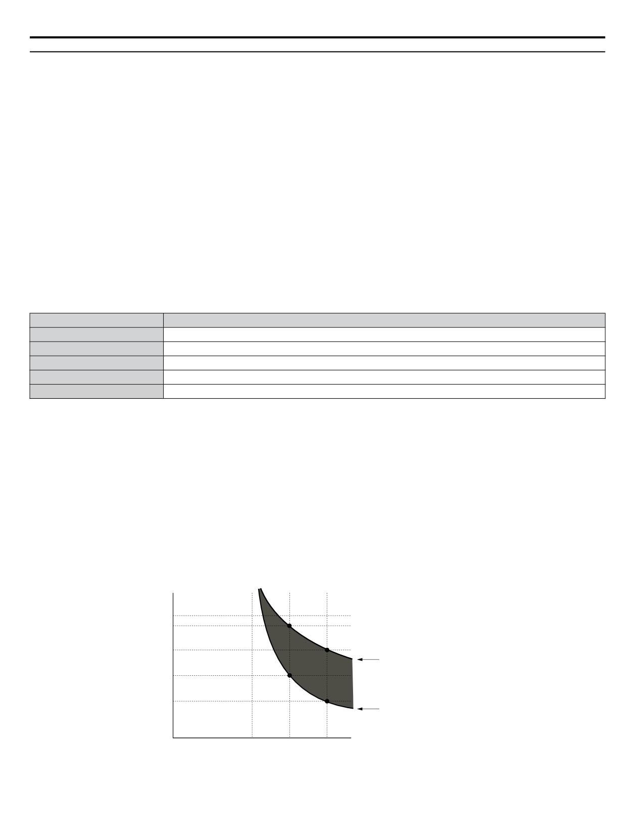
D.1 UL Standards
u Drive Motor Overload Protection
Set parameter E2-01 (motor rated current) to the appropriate value to enable motor overload protection. The internal motor
overload protection is UL listed and in accordance with the NEC and CEC.
n E2-01: Motor Rated Current
Setting Range: Model Dependent
Default Setting: Model Dependent
Parameter E2-01 (motor rated current) protects the motor if parameter L1-01 is not set to 0 (default is 1, standard induction
motor protection enabled).
If Auto-Tuning has been performed successfully, the motor data that was entered in T1-04 is automatically written into
parameter E2-01. If Auto-Tuning has not been performed, manually enter the correct motor rated current in parameter E2-01.
n L1-01: Motor Overload Protection Selection
The drive has an electronic overload protection function (oL1) based on time, output current and output frequency, which
protects the motor from overheating. The electronic thermal overload function is UL-recognized, so it does not require an
external thermal overload relay for single motor operation.
This parameter selects the motor overload curve used according to the type of motor applied.
Table D.17 Overload Protection Settings
Setting
Description
0
Disabled
1
Standard Fan-Cooled Motor (Default)
2
Drive Duty Motor with a Speed Range of 1:10
3
Vector Motor with a Speed Range of 1:100
6
Standard Fan-Cooled Motor (50 Hz)
Set L1-01 to 0 to disable the electronic overload protection and wire each motor with its own motor thermal overload when
connecting the drive to more than one motor for simultaneous operation.
Set L1-01 to 1, 2, or 3 to enable the motor overload protection when connecting the drive to a single motor unless there is
another means of preventing motor thermal overload. The electronic thermal overload function will cause an oL1 fault and
shut off the output of the drive and prevent further overheating of the motor. The motor temperature is continually calculated
while the drive is powered up.
n L1-02: Motor Overload Protection Time
Setting Range: 0.1 to 5.0 Minutes
Factory Default: 1.0 Minutes
The L1-02 parameter sets the allowed operation time before the oL1 fault occurs when the drive is running at 60 Hz and 150%
of the full load amp rating (E2-01) of the motor. Adjusting the value of L1-02 can shift the set of oL1 curves up the Y-axis of
the diagram below but will not change the shape of the curves.
Operation time (minutes)
10
7
Cold start
3
(characteristics when an
overload occurs at a
complete stop)
1
Hot start
0.4
(characteristics when an
overload occurs during
continuous operation at 100%)
0.1
Motor current (%)
0
100
150
200
E2-01 = 100% motor current
Figure D.9 Motor Overload Protection Time
440
Revision History
The revision dates and the numbers of the revised manuals appear on the bottom of the back cover.
Example:
MANUAL NO.ࠉTOEP YAIQPM 03B
Published in USA September 2015
14-12
2
Revision number
Date of original publication
Date of publication
Revision
Date of Publication
Section
Revised Content
Number
Revision: Revised NEMA/UL nomenclature to meet UL standards.
All
Addition: Safety Section to the beginning of chapters
September 2015
<2>
Chapter 5
Addition: Parameter Details chapter
Chapter 6
Addition: LED and LCD displays to tables
Appendix C
Addition: MEMOBUS/Modbus Communication appendix
Revision: Factory Recommended Branch Circuit Protection for UL
March 2015
<1>
Appendix D
Compliance
First Edition. This manual supports drive software version PRG:
December 2014
-
-
0100.
442