PL7 JUNIOR/PRO Operate modes manual (Operate modes manual eng V4.0) - page 10
Import/Export
Importing a functional module using the wizard
Introduction
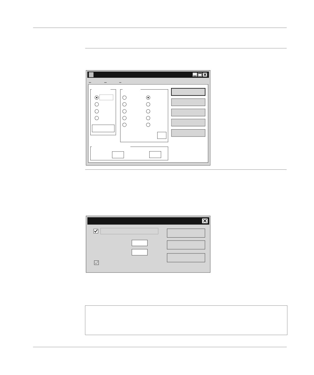
When importing with reassignment, if you want assistance check the box Open
with wizard. This tool guides you through the reassignments.
Detailed below are the different Tabs in the tool.
Directory Tree
Supports the modification of the different elements. The source name is quoted as
Tab
a prefix to the new name: Source Name => Target Name.
The entry is enabled by a double left click on the object, confirmed by the Enter
key, cancelled by the Esc key.
The different elements are:
l
Functional Module:
l The name is made up of a maximum of eight alphanumeric characters (‘A’..’Z’
and ‘0’..’9’) and underscore (‘_’), the first character obligatorily being a letter.
l The name must be unique.
l The long name associated with a functional module can be displayed and
modified in the Long name field.
l
Section, Task:
l The name is made up of a maximum of sixteen alphanumeric characters
(‘A’..’Z’ and ‘0’..’9’) and underscore (‘_’), the first character obligatorily being a
letter.
l The name of a section must be unique.
l The task associated with a section (not including the Grafcet section) can be
displayed and modified with the help of the associated pull-down menu
(MAST, FAST).
l
Grafcet and Macro-Steps:
l When the Grafcet section is imported in its entirety, it appears in the graphical
representation of the functional module, and can thus be modified.
l When Grafcet modules are imported independently of their Grafcet section,
the user can display and modify the name of the Grafcet section in the field
"Grafcet Section". This field is visible as soon as a Grafcet module is highlight-
ed in the tree directory.
l The name of the Grafcet entities PRL, POST and CHART cannot be modified.
l For the macro-steps Macro<i>, the new name entered must not be more than
a maximum of 7 characters, only their number can be modified and this num-
ber must be between 0 and 63.
l The new macro-step Macro<i> must be unique, that is no other macro-step
must have the same number, or correspond to a macro-step Target call.
366
Import/Export
l Events:
l The name is made up of a maximum of five characters. Only the modification
of their number (0..63) is allowed.
l The new event Evt<i> must be unique.
Addresses Tab
Presents the symbols and addresses of the functional module and supports modifi-
cation of the name of the different elements.
The entry is enabled by a double left click on the object, confirmed by the Enter
key, cancelled by the Esc key.
The family field supports the selection of the different imported objects:
l Standard objects are taken into account.
l Derived objects are not taken into account:
l Indexed object.
l Extract bits from indexed object.
l Indexed extract bit.
l Table.
l Indexed table.
DFB Tab
Presents the DFB instances which are declared in the functional module.
The entry is enabled by a double left click on the object, confirmed by the Enter
key, cancelled by the Esc key.
The different elements are:
l Comment:
l The comment associated with a DFB instance in the table can be displayed
and modified in the Comments field.
l The comment is written on a single scrollable line. It can contain a maximum
of 508 characters.
l Type, Source Name, Target Name:
l Type: indicates the type of a DFB.
l Source Name: indicates the source name of the instance.
l Target Name: supports the modification of the target name of every instance.
1. The name is made up of a maximum of thirty-two alphanumeric characters
(‘A’..’Z’ and ‘0’..’9’) and underscore (‘_’), the first character obligatorily being a
letter.
2. The Target name of the new instance must be unique, that is, no Target
symbol nor other instance of Target DFB, nor any DFB type can have the
same name.
l Ordering DFBs:
l In alphabetical order by the DFB type.
l In alphabetical order by the Source name of the instances.
367
Import/Export
External Calls
Presents the calls to the SRs from the functional module, and the calls to the Macro-
Tab
steps not imported with the functional module (see directory tree).
The entry is enabled by a double left click on the object, confirmed by the Enter
key, cancelled by the Esc key.
The different calls are:
l Source Call:
l Presents the source SRs and Macro steps.
l Target Call:
l Supports the modification of the target SRs and Macro steps.
l Only the modification of the SR<i> number is allowed. This number must be
between 0 and 254. The new Target call SR<i> must be unique.
l Only the modification of the M<i> number is allowed. This number must be
between 0 and 63. The new Target call must be unique.
l Ordering SRs and Macro-Steps
l First the calls to SRs then the calls to Macros-steps.
l In alphabetical order by the number of the Source call.
Correspondence
This file in text format contains all the information concerning the reassignments car-
File Zone
ried out in the different tabs described above.
This information is that defined in the tabs:
l Directory Tree.
l Addresses.
l DFB.
l External Calls.
WARNING
The correspondence information is specific to the functional module an-
alyzed. It is strongly recommended that you save your work to disk be-
fore exiting the "IMF" function, as once it is closed, all the work carried
out on the functional module is lost.
Failure to observe this precaution can result in severe injury or
equipment damage.
The commands available in the "Correspondence Files" zone are:
l Save:
l Allows you to store in a file the reassignments carried out up to that time.
l Retrieve:
l Allows you to automatically execute the reassignments previously stored in a
file.
368
Import/Export
Exporting animation table(s)
Introduction
The Export function can be accessed in local mode and in connected mode, with the
PLC in Run or Stop mode.
It supports export of:
l a single animation table via:
l the application browser,
l the animation table editor.
l a set of animation tables via:
l the application browser,
Rules
Exporting an animation table via the animation table editor or via the application
browser is only possible if the table is not being modified.
Exporting a set of animation tables via the application browser is only possible if no
animation table editor is open in modification mode.
The export can be interrupted at any moment by pressing the Escape key. After
confirming this, the export is stopped and no source file (*.TAB) is created.
Exporting via the
Carry out the following steps:
animation table
Step:
Action:
editor
1
Select the File/Export command, then the Export window is displayed on the
screen.
2
Via the Export window choose:
l in the In zone the path where the source file containing the animation table
(by default \PL7USER) is stored,
l in the Name zone the name of the source file (Nom.TAB).
3
Confirm withSave.
369
Import/Export
Exporting a set
Carry out the following steps:
of animation
Step:
Action:
tables via the
1
Select the Animation tables directory.
application
browser
2
Select the File/Export command, or from the contextual menu the Export
command, then the Export window is displayed on the screen.
3
Via the Export window choose:
l in the In zone the path where the source file containing the animation tables
(by default \PL7USER) is stored,
l in the Name zone the name of the source file (Nom.TAB).
4
Confirm withSave.
Exporting one
Carry out the following steps:
animation table
Step:
Action:
via the
application
1
Double click on the Animation tables directory.
browser
2
Select the animation table to be exported.
3
Select the File/Export command, or from the contextual menu the Export
command, then the Export window is displayed on the screen.
4
Via the Export window choose:
l in the In zone the path where the source file containing the animation table
(by default \PL7USER) is stored,
l in the Name zone the name of the source file (Nom.TAB).
5
Confirm with Save.
Errors
The only error that can arise when processing an Export is insufficient disk space
available. If this happens, an error message is displayed.
370
Import/Export
Importing animation table(s)
At a Glance
The Import function can be accessed in offline mode and in online mode, with the
PLC in Run or Stop mode.
It is used to import the following via the application browser:
l a single animation table,
l a set of animation tables.
Rules
When importing, if there is an identity problem between the name of the imported
table and a table already existing in the application, a dialog box appears offering
the option of renaming the table being imported.
When importing, only the addresses are imported but not the symbols. Therefore,
the imported animation table is slaved the application’s existing symbols database.
The import can be aborted at any moment by pressing the Escape button and after
confirming this, the import is stopped and the animation table being imported is not
imported.
For a source file containing several animation tables, the imported tables are not de-
leted.
Importing a table
Carry out the following actions:
or a set of
Step:
Action:
animation tables
1
Select the Animation tables directory.
via the
application
2
Select the File/Import command, or from the contextual menu the select the
browser
Import command. The Import window is displayed on the screen.
3
From theImport window choose:
l in the Search zone the path of the location from which the source file con-
taining the animation table(s) (by default \PL7USER) is to be read,
l in the Name zone the name of the source file (NAME.TAB).
4
Confirm with Open.
371
Import/Export
Errors
When importing, if the animation table contains a variable that is not configured in
the application, a dialog box indicating the problem is displayed, giving the option:
l of either ignoring the variable and continuing the import,
l or of interrupting the import so that the table being imported is not imported, but
the tables already imported are not deleted.
If, when importing, the source file contains:
l a reference to a DFB type that does not exist in the application, then a dialog box
is displayed indicating the conflict, giving the option:
l of either ignoring the variable and continuing the import,
l or of interrupting the import so that the table being imported is not imported,
but the tables already imported are not deleted.
l a reference that does not exist in the application, but whose DFB type does exist,
then a dialog box is displayed indicating the conflict, and giving the option:
l of either ignoring the variable and continuing the import,
l or of interrupting the import so that the table being imported is not imported,
but the tables already imported are not deleted.
372
Import/Export
Export of runtime screens
Introduction
PL7 is used to export runtime screens or families of runtime screens.
The Export function can be accessed in offline mode and in online mode, with the
PLC in Run or Stop mode.
How to export a
Carry out the following steps:
runtime screen
Step
Action
(or a family)
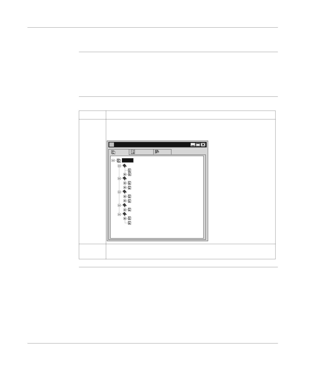
1
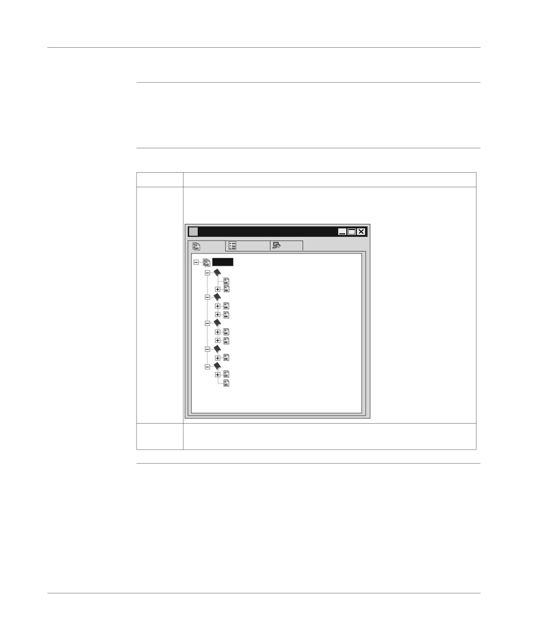
In the Application Browser in the structure view double click on the Runtime
screens directory.
Result:
Ecrans d’exploitation
Ecrans
Messages
Objets
Ecran
ACCUEIL
3 - Lisez_moi
1 - Ecran_accueil
INFORMATIONS SYSTEME
7 - Bit systèmes
6 - Grafcet
DOSAGE_PRODUITS
2 - Ecran_ controle
0 - Dosage_Melange_Produits
DIAGNOSTIC_APPLICATION
8 - Surveillance_malaxeur
COMPORTEMENT DFB
4 - Ecran_comportement_DFB
5 - Informations_sur_mise_au_point_DFB
2
Right click on one of the runtime screen items or on a family directory (example
here: Home, Information system…).
373
Import/Export
How to export a
Carry out the following steps (next):
runtime screen
Step
Action
(or a family)
3
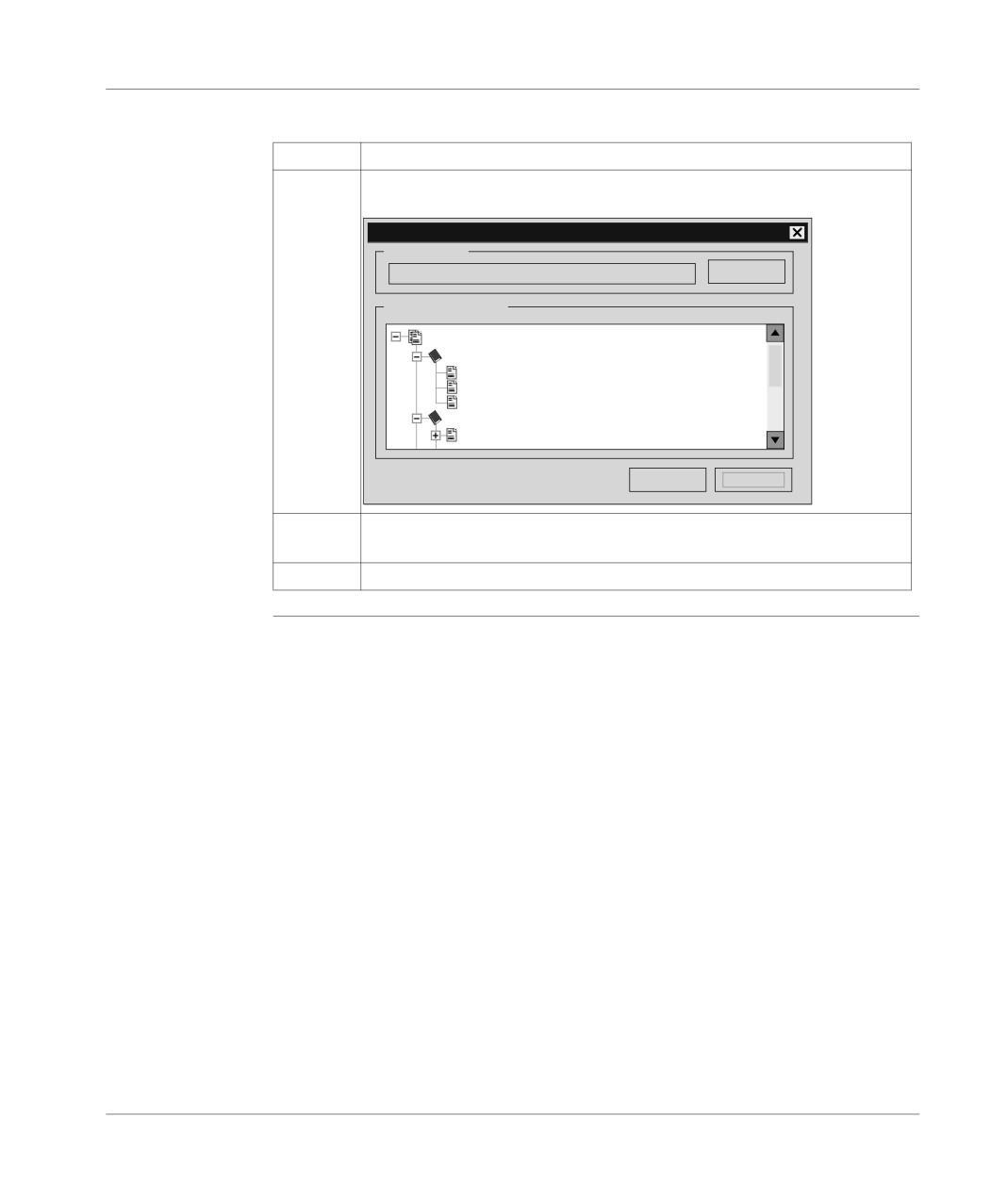
Select the Export command.
Result:
Exporter des écrans
Exporter vers
c:\PL7USER
Parcourir...
Sélection des écrans
Ecran
ACCUEIL
Lisez_moi
Ecran_accueil
Copie de Ecran_accueil
INFORMATIONS SYSTEME
7 - Bit systèmes
Exporter
Annuler
4
Choose the directory from which you wish to import the screen or the family of
screens.
5
Select the screen and click on Export.
374
Import/Export
Import of runtime screens
Introduction
PL7 can be used to import runtime screens or runtime screen families into your ap-
plications.
The Import function can be accessed in offline mode and in online mode, with the
PLC in Run or Stop mode.
How to import a
Carry out the following steps:
runtime screen
Step
Action
(or a family)
1
In the Application Browser in the structure view double click on the Runtime
screens directory.
Result:
Ecrans d’exploitation
Ecrans
Messages
Objets
Ecran
ACCUEIL
3 - Lisez_moi
1 - Ecran_accueil
INFORMATIONS SYSTEME
7 - Bit systèmes
6 - Grafcet
DOSAGE_PRODUITS
2 - Ecran_ controle
0 - Dosage_Melange_Produits
DIAGNOSTIC_APPLICATION
8 - Surveillance_malaxeur
COMPORTEMENT DFB
4 - Ecran_comportement_DFB
5 - Informations_sur_mise_au_point_DFB
2
Right click on one of the runtime screen items or on a family directory (example
here: Home, Information system…).
375
Import/Export
How to import a
Carry out the following steps (next) :
runtime screen
Step
Action
(or a family)
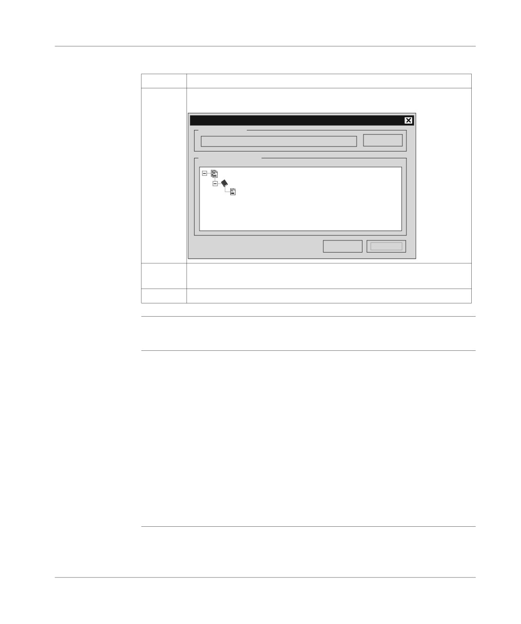
3
Select the import command.
Result:
Importer des écrans
Importer depuis
c:\PL7USER
Parcourir...
Sélection des écrans
Ecran
ACCUEIL
Ecran_accueil
Importer
Annuler
4
Choose the directory from which you wish to import the screen or the family of
screens.
5
Select the screen(s) and click on import.
Export of a DFB type
At a Glance
Export of a DFB type is global and includes:
l the properties of the DFB type,
l the descriptive form,
l the description of public interfaces (inputs, inputs/outputs, outputs) and public
variables,
l the description of private variables,
l the code.
A DFB type can be exported from the application browser or the DFB type editor.
Two export formats are offered:
l standard (unprotected DFB types ),
l binary (protected (See How to protect a DFB, p. 269) or unprotected DFB types).
Exporting a
The Export function can be accessed in local mode and in online mode, the PLC in
standard format
Stop.
DFB type
376
Import/Export
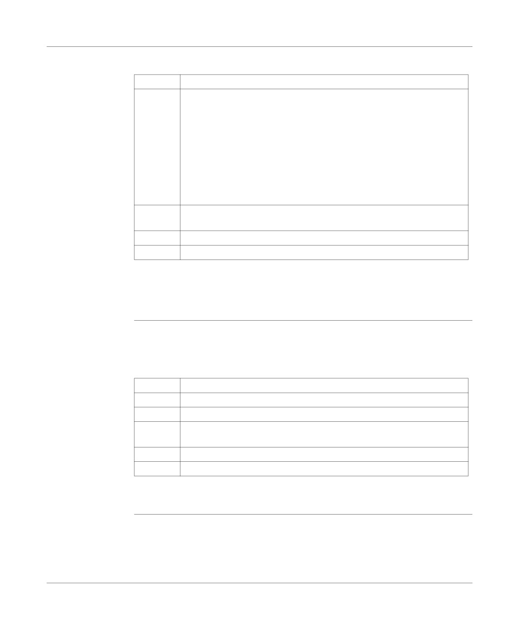
Carry out the following actions:
Step
Action
1
l Export from the application browser:
1. Left mouse click on the DFB type or put the cursor over it using the arrow
keys.
2. From the context menu or the File menu or using the keys Shift+F10, se-
lect the Export command.
l Exporting from the DFB type editor:
1. Left mouse click on the DFB type or put the cursor over it using the arrow
keys.
2. Edit the DFB type right mouse click + Open key.
3. From the File menu, select the Export command.
2
Select the disk and/or directory where the file must be saved using the pull-
down menu In.
4
Enter a file name in the Name field.
5
Confirm using Save.
Comments:
Export from the DFB type editor is authorized whether DFB type is enabled or not.
Only an enabled DFB type can be exported from the application browser.
Export of a
The Export binary function can be accessed in local mode and in online mode, the
binary format
PLC in Stop.
DFB type
Carry out the following actions:
Step
Action
1
Left mouse click on the DFB type or put the cursor over it using the arrow keys.
2
From the context menu or using the keys Shift+F10 select Export binary.
3
Select the disk and/or directory where the file must be saved using the pull-
down menu In.
4
Enter a file name in the Name field.
5
Confirm using Save.
Comment:
Export is possible if the DFB type is enabled.
377
Import/Export
Importing a DFB type
Introduction
The Import function is only accessible in local mode.
The DFB type is imported from within the application browser.
The import of a DFB type is global and includes:
l the properties of the DFB type,
l the descriptive form,
l the description of the public interfaces (inputs, inputs/outputs, outputs) and public
variables,
l the description of the private variables,
l the code.
Importing a DFB
Carry out the following actions:
type in binary
Step
Action
format
1
Left mouse click on the directory DFB Type or position the cursor over it using
the arrow keys.
2
Using the Contextual menu or the File menu or the keys Shift+F10 select the
command Import.
3
Select the source file *.DFB relating to the type to be imported.
4
Confirm with Import.
Importing a DFB
carry out the following actions:
type in binary
Step
Action
format
1
Left mouse click on the directory DFB Type or position the cursor over it using
the arrow keys.
2
Using the Contextual menu select the command Import binary.
3
Select the source file *.UFB relating to the type to be imported.
4
Confirm with Import.
378
Import/Export
Specific cases
It is possible that the DFB type to be imported is already present in the application.
Three cases are possible:
l The DFB type present in the application is protected:
l In this case the import is impossible.
l The DFB type present in the application is not protected and not instanced:
l A dialog box offers to replace, rename, cancel the import of the DFB type.
l The DFB type present in the application is not protected but instanced:
l If the interfaces are identical, a dialog box offers to replace, rename or cancel
the import of the DFB type.
l If the interfaces are different, the import is impossible. It is then necessary to
delete the instances first.
379
Import/Export
Exporting an application
Introduction
The Export an application function can be accessed in local mode and in connected
mode, with the PLC in Stop mode.
Exporting an
Carry out the following actions:
application
Step
Action
without DFB
1
Open the application to be exported.
2
On the File menu select the command Export an application, or from the di-
rectory Station using the Contextual menu or using the keys Shift+F10 select
Export an application.
3
Select the disk and/or the directory where the file is to be saved using the pull-
down menu In.
4
Enter a file name in the field Name.
5
Confirm withSave.
Exporting an
Exporting an application only takes into account the enabled DFB types.
application with
DFB
Two cases are possible:
l Non protected DFB(s):
l All the contents of the DFB(s) are saved in the resulting export file *.FEF.
l Protected DFB(s) or DFB(s) exported from PL7-Junior:
l Only the names of the DFB type are saved in the resulting file *.FEF.
l The binary format of the DFB(s) (*.UFB) must also be exported (see Exporting
a DFB type (See Export of a DFB type, p. 376)).
In the two cases, the Export procedure is identical to that described above.
Exporting an
Exporting the application includes all the animation tables contained in the directory
application with
Animation tables in the application browser.
animation tables
The source file of the application (NomAppli.FEF) contains the source of the anima-
tion tables.
The Export procedure is identical to that described above.
380
Import/Export
Exporting an
The export of the application leads to the creation of a directory.
application with
operating
This directory NomRep.FEF contains:
screens
l the source file NonAppli.FEF,
l a directory ECREXP in which the tree structure dedicated to the operating
screens is located.
The Export procedure is identical to that described above.
381

Import/Export
Importing an application
At a Glance
The Import application function can be accessed in offline and online mode, with the
PLC in Stop mode.
The Import application function involves:
l redefining the inputs/outputs,
l finding and replacing modified objects,
l initializing the station with the new application obtained.
Importing an
Carry out the following actions:
application
Step
Action
without DFBs
1
Create an empty application.
2
Using the Contextual menu, the File menu or the keys Shift+F10 select the
command Import an application.
3
Select the *.FEF file to be imported.
4
Confirm with Open.
5
If applicable correct any non configured objects.
6
Click on OK.
Importing an
The function Import an application with DFB is only accessible in offline mode.
application with
DFBs
There are two possible scenarios:
l Non protected DFB(s):
l Their contents which are saved in the *.FEF are imported in the same way as
the rest of the application.
l The Import procedure is the same as that described above.
l Protected DFB(s):
l When Importing, a dialog box asks for the pathname of the binary file(s)
(*.UFB) in order to import them.
Carry out the following actions:
Step
Action
1
Create an empty application.
2
Using the Contextual menu, the File menu or the keys Shift+F10 select the
command Import an application.
3
Select the *.FEF file to be imported.
4
Confirm with Open.
5
If applicable correct any non configured objects.
382
Import/Export
Step
Action
6
Click on OK.
7
Using the Find drop-down menu, enter the name of the disk and/or directory
where the first type of DFB in the (*.UFB) list is located.
8
Confirm withImport.
Importing an ap-
The application import incorporates all the animation tables contained in the file
plication with
NAME.FEF.
animation tables
If any non configured variables are present in the application, a list appears allowing
the user to modify the current configuration and continue with the import.
The Import procedure is identical to those described above.
Errors
Three possible scenarios:
l Importing an application without DFBs:
l An error message is displayed.
l Importing an application with DFBs:
l An error can appear if:
-The source file has been modified with a text editor.
-The DFB type is not present on the station onto which the application is im-
ported.
-The DFB type is of a different application identification and is incompatible.
l An error message is displayed, and the station is reinitialized to the application
by default.
l Importing an application with animation tables.
383
Import/Export
Exporting an application in FNES format (Input/Output Neutral File)
Introduction
The FNES file (Input/Output Neutral File) generated by an export can only be used
with a single PLC.
It contains the description of all the symbolized Inputs/Outputs, except for discrete
Inputs/Outputs when all the Inputs/Outputs are described (symbolized or not).
This functionality is only accessible in local mode.
This functionality is not accessible (menu grayed out) if a modification is being car-
ried out in the editor and vice versa, during the execution of an Export, no other ac-
tion is possible in the editor.
Only the software PL7 Pro allows access to the Export/Import FNES functionality.
Procedure
Carry out the following actions:
Step
Action
1
From the Station directory on the Contextual menu or using the File menu or
the keys Shift+F10, select Export/Import FNES+Export FNE.
2
Select the destination directory and indicate the name of the file (*.FNE),
3
Click on Save.
Notes:
The export can be interrupted by the user using the Escape key, in this case, no FNE
file is exported.
The default directory offered is that on the Customize Options/Source directory
menu, subsequently, the offered directory will always be the last entered (for the cur-
rent PL7 session).
Errors
The errors that can arise when processing an Export are insufficient disk space
available or a problem retrieving data.
An error message is displayed and the process is interrupted. If this happens, no file
is generated.
384
Import/Export
Importing an application in FNES format
At a Glance
Importing a FNES file (Input/Output Neutral File) allows you to increment the appli-
cation’s symbols database, but does not modify its configuration data in any way.
Inserting symbols into an existing symbols database involves managing the follow-
ing conflicts:
l Address conflict:
l The symbol to be read already exists in the symbols database, but represents
a different address.
l Symbol conflict:
l The address to be read is already represented in the symbols database, but
by a different symbol.
l Comment conflict:
l The address to be read is represented in the symbols database already, by the
same symbol, but the 2 comments associated with them are different.
To deal with this, 3 import modes are offered:
l Overwrite mode (to overwrite symbol database):
l Priority is given to the contents of the FNES file.
l Do not overwrite mode (does not overwrite symbols database):
l Priority is given to the contents of the symbols database.
l Dialog mode (default mode):
l The user chooses the priority depending on the conflict displayed.
This function can only be accessed in offline mode.
This function cannot be accessed (menu grayed out) if a modification is in progress
in the editor and conversely, during Import execution, no other actions are possible
in the editor.
Only PL7 Pro software provides access to the Import/Export FNES function.
385
Import/Export
Procedure
Carry out the following actions:
Step
Action
1
From the Station directory using the Contextual menu, the File menu or the
Shift+F10 keys, select Import/Export FNES + Import FNE.
2
Select the source directory and give the file name (*.FNE).
3
Select import mode:
l overwrite mode,
l do not overwrite mode,
l dialog mode.
4
Confirm with Open.
Notes:
The import can be aborted by pressing the Escape key.
The import is aborted after restoring the current object, but the objects that have al-
ready been imported remain.
The directory proposed by default is that specified in the Options/Customize/
Source directory menu. Subsequently, the proposed directory will always be the
last entered (for the current PL7 session).
If several PLCs are present in the file, a message is displayed giving the user the
possibility of consulting the list of PLCs or of canceling the import.
If the user chooses to continue the import, the list of associated applications and pro-
cessors is displayed.
Errors
There are two possible scenarios:
l Blocking error:
l These errors interrupt the import. They can only occur if the FNE file was gen-
erated outside of PL7 Pro (e.g.: bad syntax in the FNE file).
You must abort the import, correct the error (fix the FNE file), then restart the
desired Import.
l Non blocking error:
l Example: error caused by a collision or bad configuration.
You must replace the symbol or symbols already configured or cancel the im-
port.
386
Configuring the Uni-telway link
18
Introduction
Subject
This chapter describes how to configure the Uni-telway driver.
What’s in this
This Chapter contains the following Maps:
Chapter?
Topic
Page
General
388
Configuration of the terminal/PLC link
390
Advanced configuration
396
387
Configuring the Uni-telway link
General
At a Glance
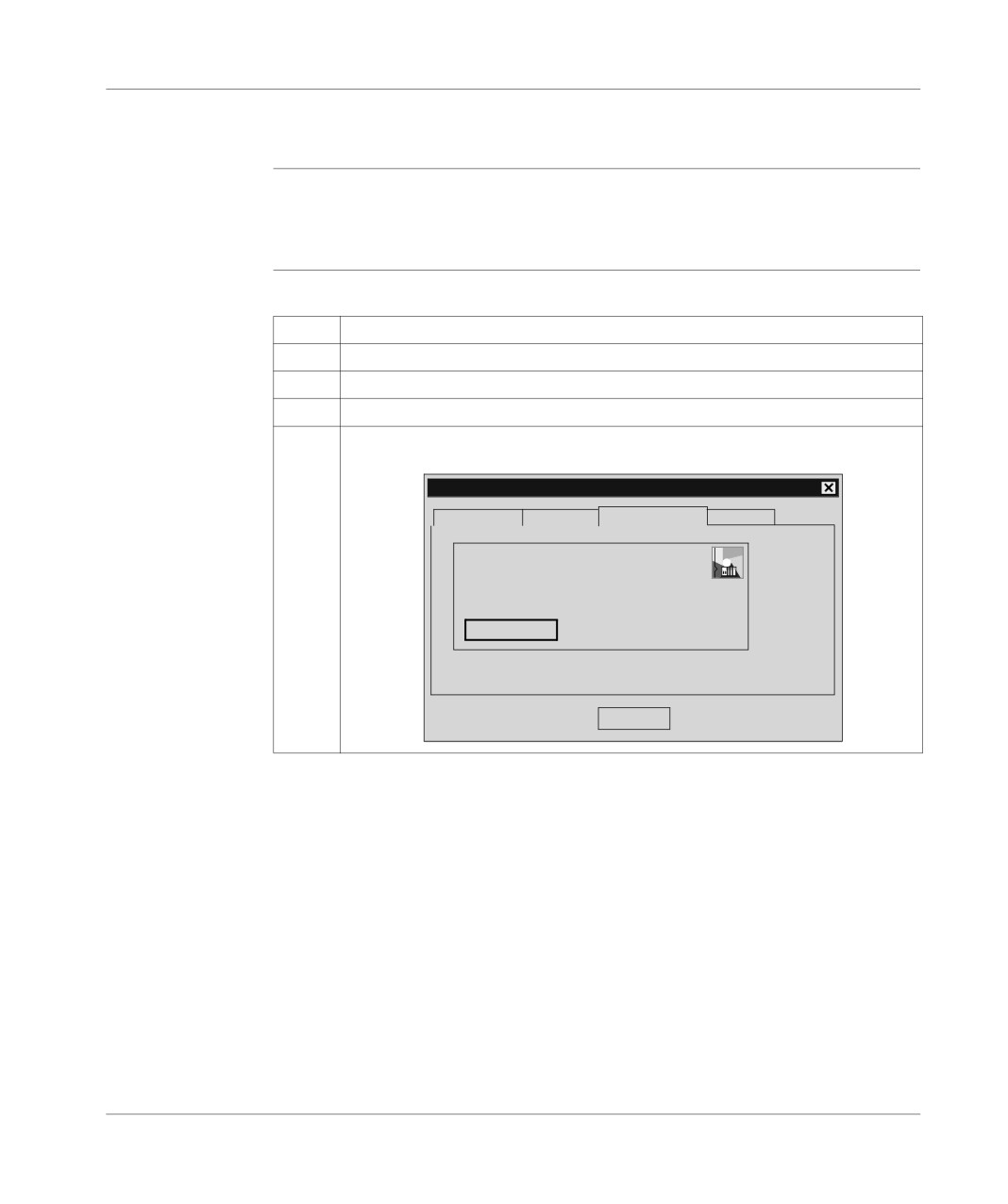
The Uni-telway tool is used to configure the operating parameters of the Uni-Telway
driver depending on the PLC’s terminal port characteristics.
How to configure
The following table describes the procedure for configuring the UNITELWAY driver.
the UNITELWAY
Step
Action
driver
1
From the Start menu select the Program group.
2
Select the Modicon Telemecanique program group.
3
Select XWAY Driver Manager.
4
Click on the UNITELWAY tab.
Result: the following window appears:
Management properties of XWAY drivers
XWAY Manager FPC10 Driver
UNITELWAY Driver
XWAY Test
FPW
UNITELWAY Driver V7.7 IE17
Status: In service
Configuration
OK
388
Configuring the Uni-telway link
Step
Action
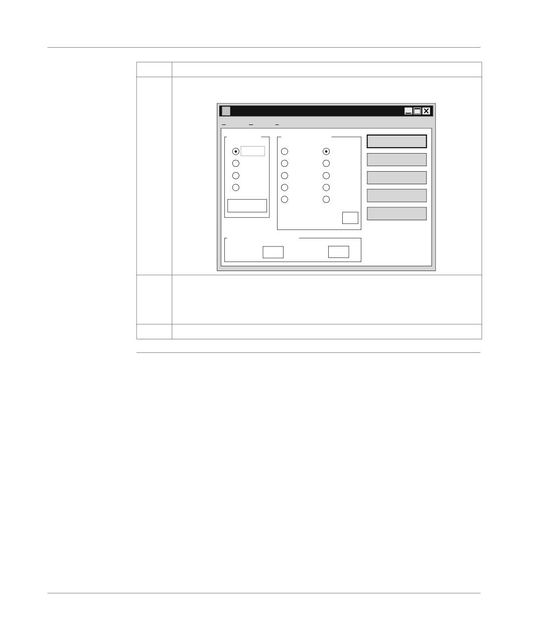
5
Click on the Configuration button.
Result: The dialog box below appears:
Configuration UNI -TELWAY - UNTLW01
Fichier Edition
?
Port COM
Vitesse (bauds)
Enregistrer
COM1
300
9600
Ouvrir
COM2
600
19200
COM3
1200
38400
Par défaut
COM4
2400
57600
Modem
4800
115200
Param...
Auto adaptation
Maître
1
(en secondes)
Adresse UNI-TELWAY
Base
1
Nombre
3
6
Configure:
l the communication port,
l the transmission speed,
l the UNITELWAY address.
7
Click on Save.
389
Configuring the Uni-telway link
Configuration of the terminal/PLC link
At a Glance
Various configuration parameters are available for the Uni-telway driver.
Main configuration screen.
UNI-TELWAY Configuration - UNTLW01
File
Edit
?
COM Port
Baud rate
Save
COM1
300
9600
Open
COM2
600
19200
COM3
1200
38400
By default
COM4
2400
57600
Modem
4800
115200
Param…
Auto adaptation
Master
1
(in seconds)
UNI-TELWAY Address
Base
1
Number
3
Description of
This zone allows you to select the terminal serial port (COM1 to COM4), to be used
the COM Port
for Uni-telway communication. The default value is COM1 (COM2 on TELEMECA-
zone
NIQUE FTX or CCX terminals).
Use the other COMs according to the availability on your hardware.
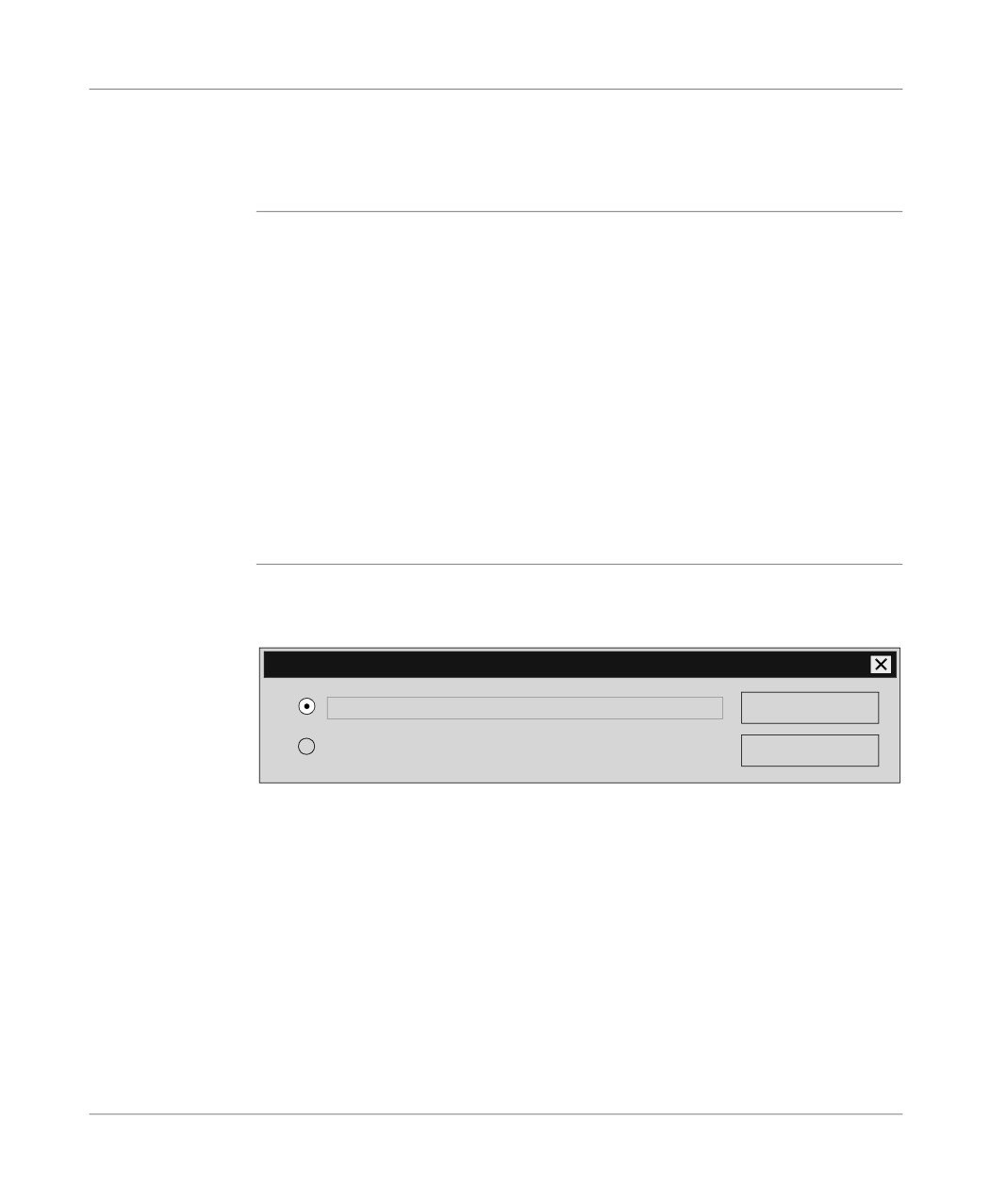
The Param. button makes the following dialog box appear:
UNI-TELWAY Configuration- Port
Automatic Configuration
OK
I/O Address
Auto
Cancel
Interrupt
Auto
By default
RS485 Port
This allows you to force the hardware configuration of the selected serial port. By
default, the configuration is determined automatically by the driver at start up.
Note: apart from with the generally marginal use of serial link cards or internal mo-
dems which do not comply with the normal values used for the serial port’s hard-
ware configuration, it is advisable to select Automatic configuration. When this
box is ticked, you no longer have access to I/O address, Interrupt and RS 485 Port.
390
Configuring the Uni-telway link
Using the COM 2 port in RS 232 C
The FTX 417-40 terminal allows the use of the COM 2 port in serial link RS 232C.
This type of use necessitates the deselection of theAutomatic configuration and
RS485 Port boxes.
Description of
Speed Zone (bauds):
the speed zone
This zone is used to select the standard speed of the serial link, from 300 to 115200
and the address
bauds. If the actual link speed is different from the selected speed, the auto driver
zone
adapts its speed. The Auto adaptation field defines the auto adaptation mechanism
time in seconds. The driver automatically changes its speed after n seconds if the
connection is not established at the current speed. Auto adaptation is disabled for a
value of 0. The values by default are 9600 bauds for the speed and 1 second for the
auto adaptation.
Uni-telway address zone:
This zone is used to select the standard link address as well as the number of ad-
dresses to which the Uni-telway driver responds. The default values are 1 for the
standard address and 3 for the number of addresses that respond to the following
configuration: Ad0=1, Ad1=2, Ad2=3 (Ad0 corresponding to the server address, Ad1
to the client application address and Ad2 to the listening application address).
Description of
Save button:
the Save button
is used to save the Uni-telway driver configuration.
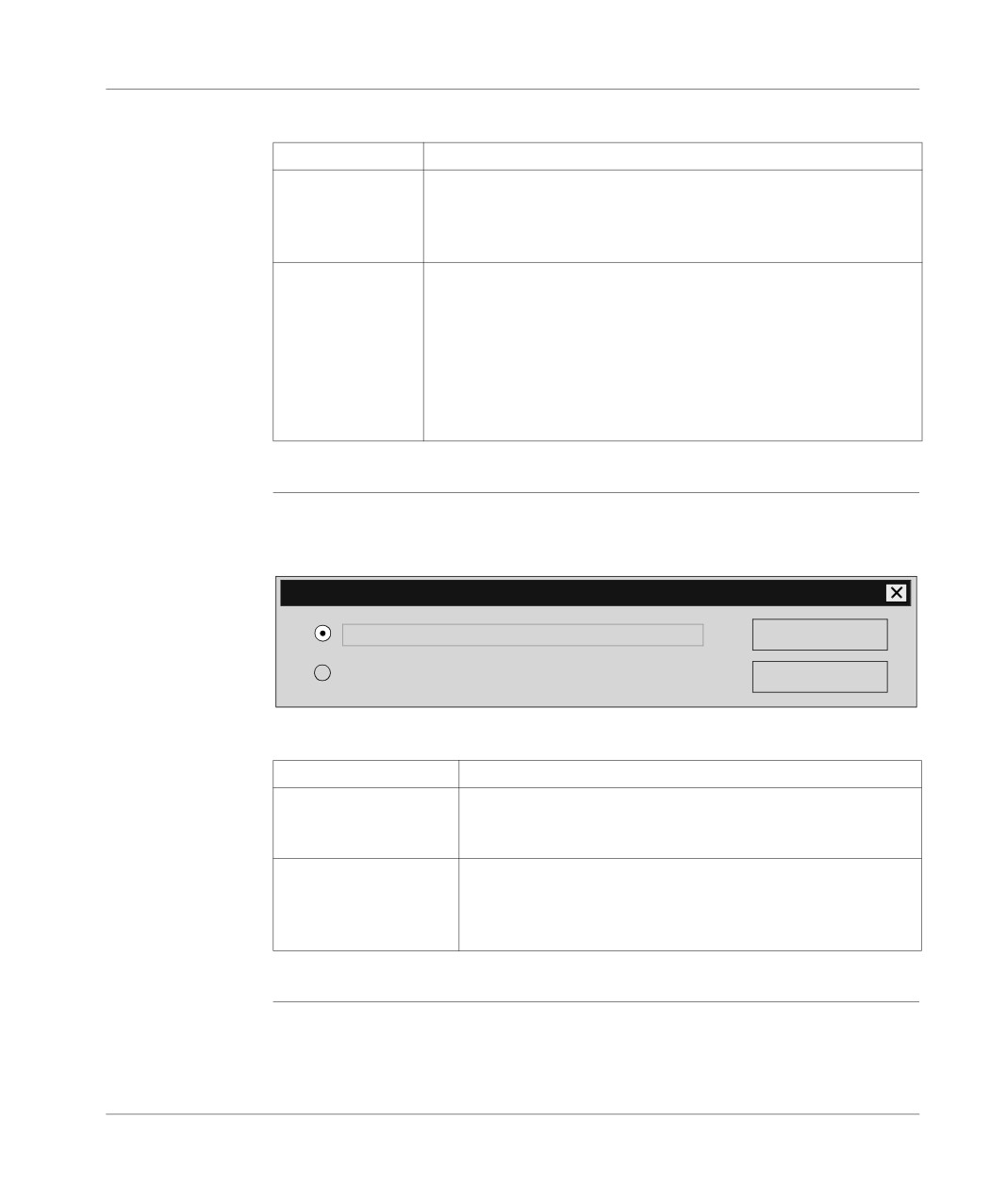
The Save button appears in the following dialog box:
UNI-TELWAY Configuration- Save
Save configuration file (DUNTLW.00?)
OK
Dynamically reinitialize driver (in the memory)
Cancel
391
Configuring the Uni-telway link
Elements and their functions:
Element
Function
Saving a configura-
The configuration of the Uni-telway driver is saved in a configuration file
tion file
on disk (usually DUNTLW.001 in the xwaydrv directory). This file is
(DUNTLW.00?
read by the driver when the computer boots up. The modifications will
therefore be acknowledged the next time the computer is started.
Dynamically reini-
The configuration is directly described in the driver memory. Modifica-
tialize the driver (in
tions are acknowledged immediately by the driver.
memory)
Dynamic reinitialization is impossible:
l if the driver is not loaded into the memory (at installation, for exam-
ple),
l if the modifications relate to parameters that cannot be dynamically
modified (the COM port, for example),
l if the driver is being used (if the PL7 is connected, for example).
Description of
The Open button:
the Open button
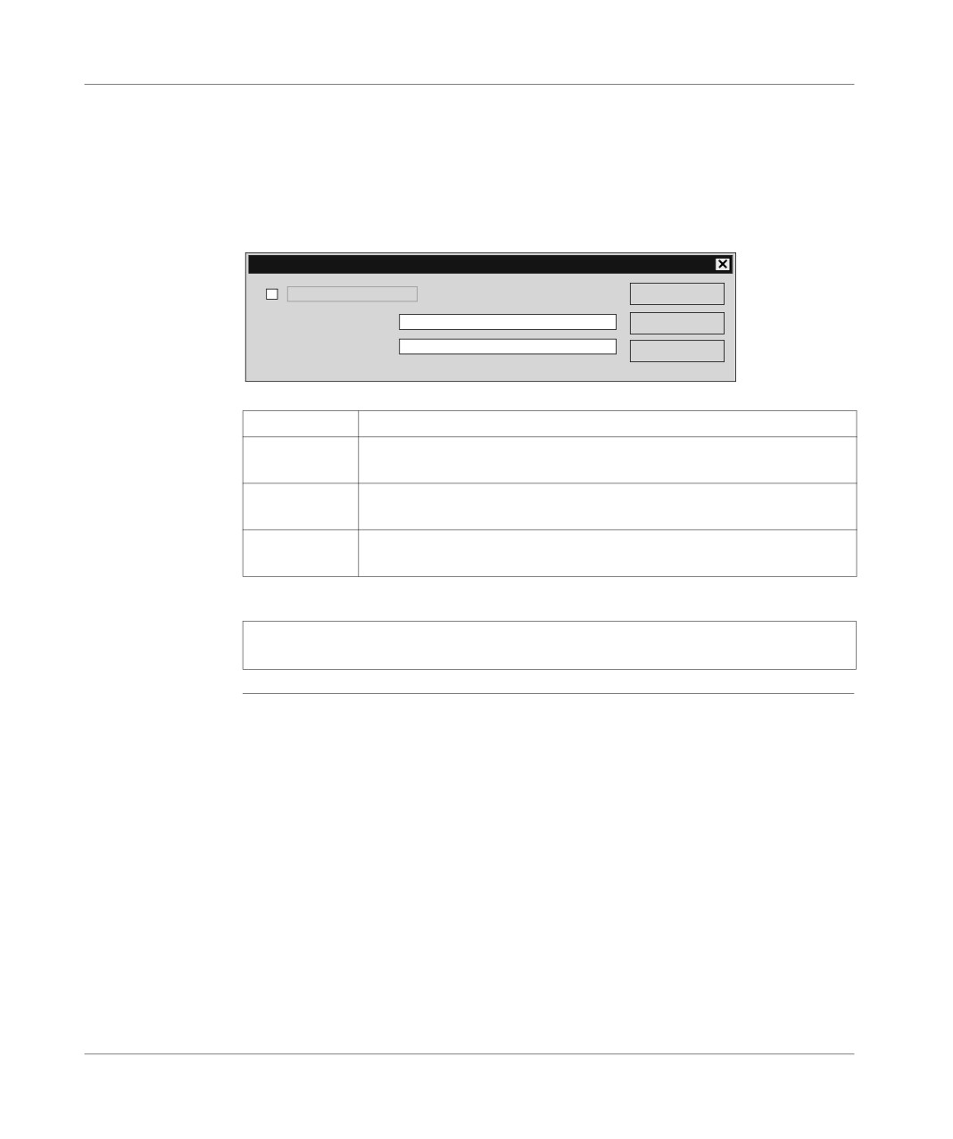
is used to read the Uni-telway driver configuration.
The Open button appears in the following dialog box:
UNI-TELWAY Configuration- Open
Open configuration file (DUNTLW.00?)
OK
Read current driver configuration (from memory).
Cancel
Elements and their functions:
Element
Function
Open a configuration file
The configuration of the Uni-telway driver is read in a configura-
(DUNTLW.00?)
tion file on disk (usually DUNTLW.001). From this, you can view
and modify the driver’s initial configuration (read upon start-up).
Read current driver con-
The configuration is read directly in the driver memory. From this
figuration (in memory)
you can view and modify the driver’s real time configuration. This
selection is deactivated if the driver is not loaded into the memory
(at installation, for example).
392
Configuring the Uni-telway link
Description of
The Default button:
the Default
is used to reset the values of the COM Port, Speed (bauds) and Uni-telway groups
button and the
to their default values, to port COM1 (COM2 for FTX or CCX terminals), speed 9600
Modem button
bauds, auto adaptation 1 second, standard address 1 and number of addresses 3.
The Modem button:
is used to select the use of a MODEM and the associated parameters.
The Modem button makes the following dialog box appear:
UNI-TELWAY Configuration- MODEM
MODEM connection
OK
Telephone number
Cancel
HAYES Initialization
ATV1E0B0F0&M0X4&E0&D2D
By default
Elements and their functions:
Element
Function
Connection by
Is used to select the management of the MODEM by the driver.
MODEM
Telephone
Is used to enter the telephone number of the remote MODEM to be called.
number
HAYES Initial-
Is used to define the HAYES command string emitted by the driver in order
ization
to initialize the MODEM each time it connects.
Note: Consult the documentation of your MODEM to ensure that it is initialized cor-
rectly. By default the MODEM connection is disabled.
393
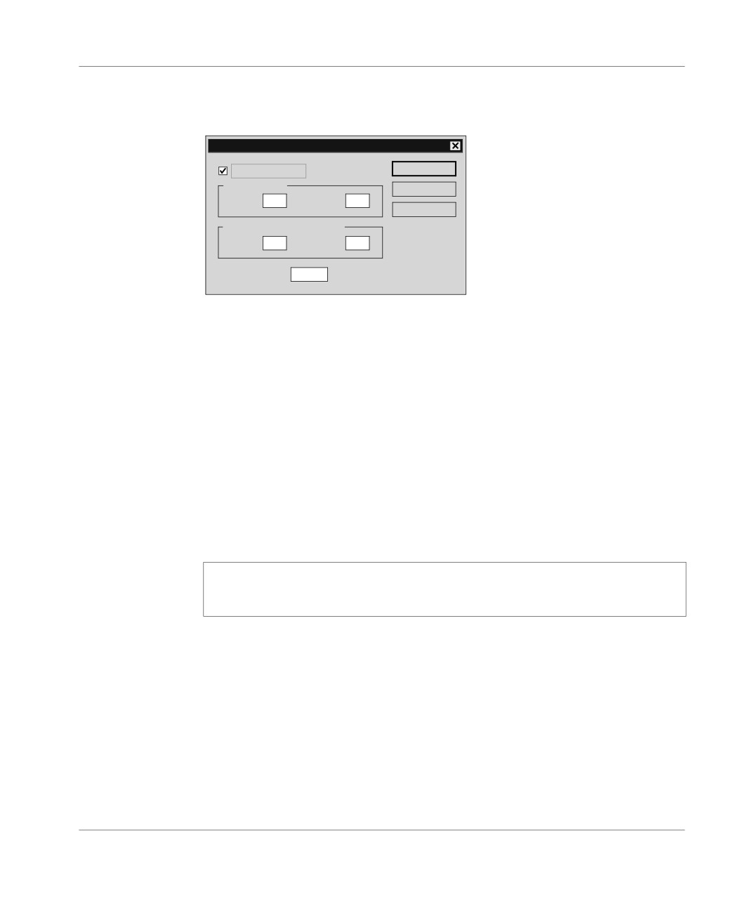
Configuring the Uni-telway link
Description of
The Master button:
the Master
is used to activate the Uni-telway protocol in master mode on the PC.
button
The Master button makes the following dialog box appear:
UNI-TELWAY Configuration - Master
UNITELWAY master
OK
Polled slaves
Cancel
Base
1
Number
31
By default
Reserved slaves (not polled)
Base
1
Number
3
TimeOut (ms)
100
The Uni-telway master check box is used to select the protocol management in
master mode on the PC.
The Base and Number fields respectively are used to input the first slave and the
number of slaves on the PC which may or may not need to be scanned. The default
values are base 1 and number 31.
With Polled Slaves the Base will inform the master of the slave address from which
it will start to scan and the Number will be the number of slave addresses to scan.
With Reserved Slaves (not polled), these are the addresses that the PC reserves
for applications using the Uni-telway driver which transmit to the slaves. The Base
will therefore be the first address and the Number will depend on the application us-
ing the driver (with PL7, Number=3). These addresses must not be used by a slave.
The Time Out field gives the polling response time in milliseconds.
Note: it is not advisable to enter a value lower than the 100ms default value, be-
cause of the PC’s timing constraints (high CPU consumption for low timeouts). By
default, master mode is disabled.
394
Configuring the Uni-telway link
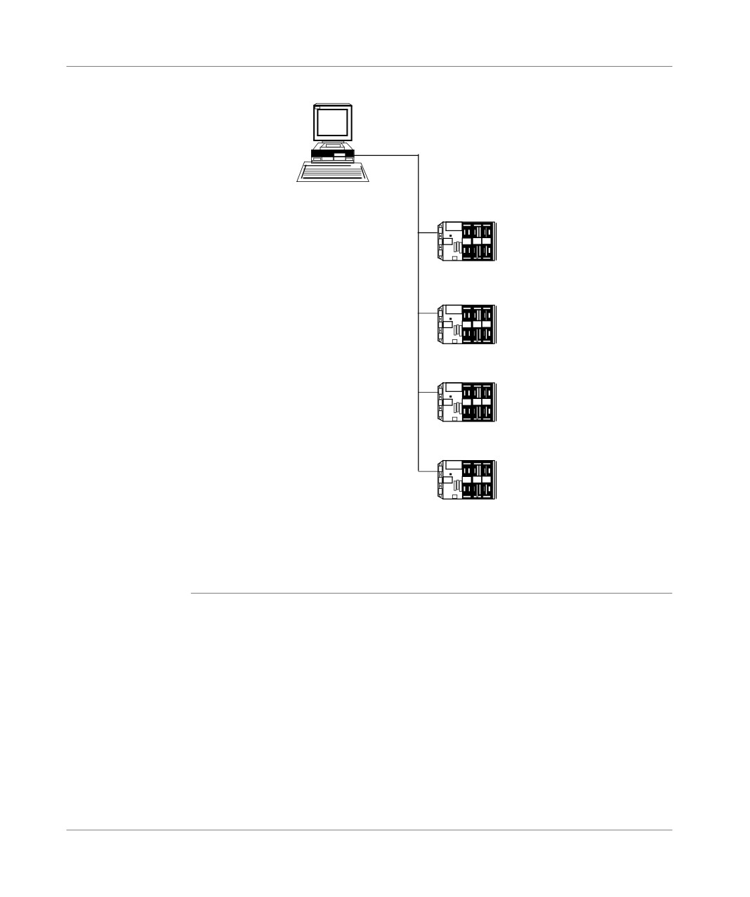
the following diagram shows a configuration example:
Ad0=1
Slave 1
Ad1=2
Ad2=3
Ad0=4
Ad0=5
Slave 2
Ad0=6
Ad0=7
Slave 3
Ad0=8
Ad0=9
Ad0=10
Slave4
In this case the configuration will be Uni-telway-Master:
Polled slaves
Base=1 and Number=10
Reserved slaves (not polled)
Base=11 and Number=3 (if the PL7 is using the Uni-telway driver).
395
Configuring the Uni-telway link
Advanced configuration
At a Glance
An advanced configuration is also available for the Uni-telway driver.
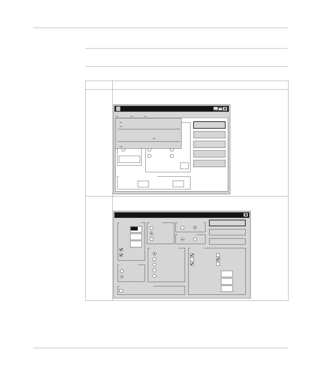
How to access
The following table describes how to access advanced configuration:
advanced
Step
Action
configuration for
the Uni-telway
1
From the configuration window click on File then select Advanced configura-
driver
tion, as shown in the following window:
Configuration UNI -TELWAY - UNTLW01
Fichier Edition
?
Enregistrer
Ctrl+E
Ouvrir
Ctrl+O
Enregistrer
0
Configuration Avancée
Ctrl+A
Ouvrir
Tous paramètres par Défaut
Ctrl+D
00
00
Par défaut
Quitter
COM4
2400
57600
Modem
4800
115200
Param...
Auto adaptation
Maître
1
(en secondes)
Adresse UNI-TELWAY
Base
1
Nombre
3
2
Click on advanced configuration.
Result: the following window appears:
Configuration UNI-TELWAY - Avancée
Buffers driver
Parité
Bits de données
OK
SBUF
16
Sans
7
8
Impaire
Bits de
Annuler
RBUF
3
Paire
1
2
Par défaut
ABUF
0
Types de cable
Divers
IBUF
Page
Tous types
COM share
Read
TSXSCA72
Hold COM
Enable FIFO
Adressage
TSXSCA72+
Use VCD
NUM PLC
Version 3
TFTXCBP02
Link TimeOut
-1
Version 5
RS232
RXTX Delay
-1
Power Management
Ack TimeOut
1000
Dévalider l’APM en connecté
396
Configuring the Uni-telway link
CAUTION
Advanced parameters may only be modified by special instruction from
the software using the Uni-telway driver or under the supervision of the
technical support department of Schneider Automation SA.
Failure to observe this precaution can result in injury or equip-
ment damage.
397
Configuring the FIPWAY link
19
Presentation
Subject of this
This chapter describes configuration operations for the FIPWAY driver.
chapter
What’s in this
This Chapter contains the following Maps:
Chapter?
Topic
Page
General
400
Configuring the terminal/FIPWAY link
402
Advanced Configuration
406
399
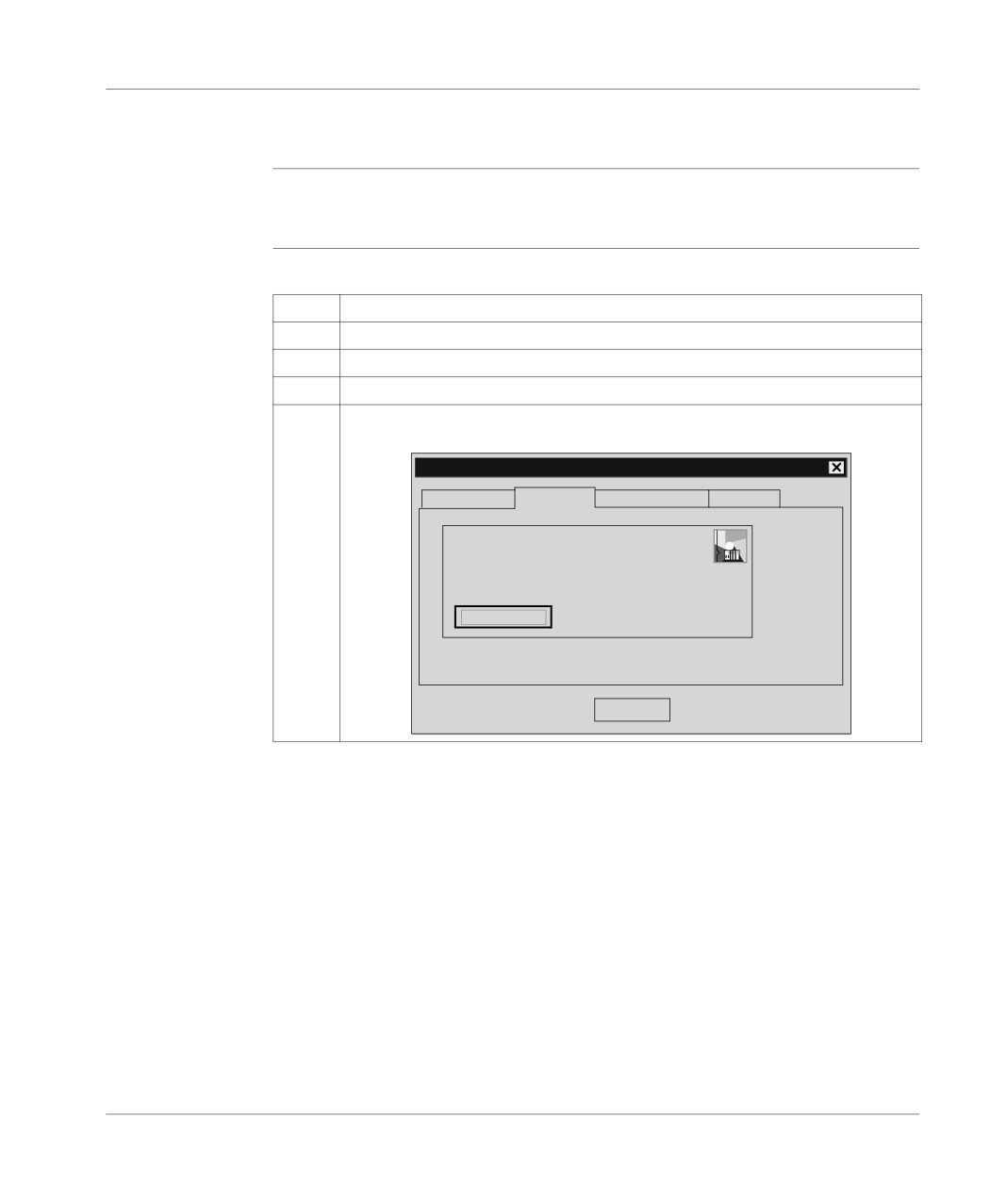
Configuring the FIPWAY link
General
At a Glance
The FIPWAY tool is used to configure the operating parameters of the terminal’s
FIPWAY driver.
How to configure
The following table describes the procedure for configuring the FIPWAY driver.
the FIPWAY
Step
Action
driver
1
From the Start menu select the Program group.
2
Select the Modicon Telemecanique program group.
3
Select XWAY Driver Manager.
4
Click on the FPC10 Driver tab.
Result: the following window appears:
Management properties of XWAY drivers
XWAY Manager
FPC10 Driver
UNITELWAY Driver
XWAY Test
FPW
FPC10 Driver V2.3 IE 12
Status driver 1: Non operational
Status driver 2: Non operational
Configuration
OK
400
Configuring the FIPWAY link
Step
Action
5
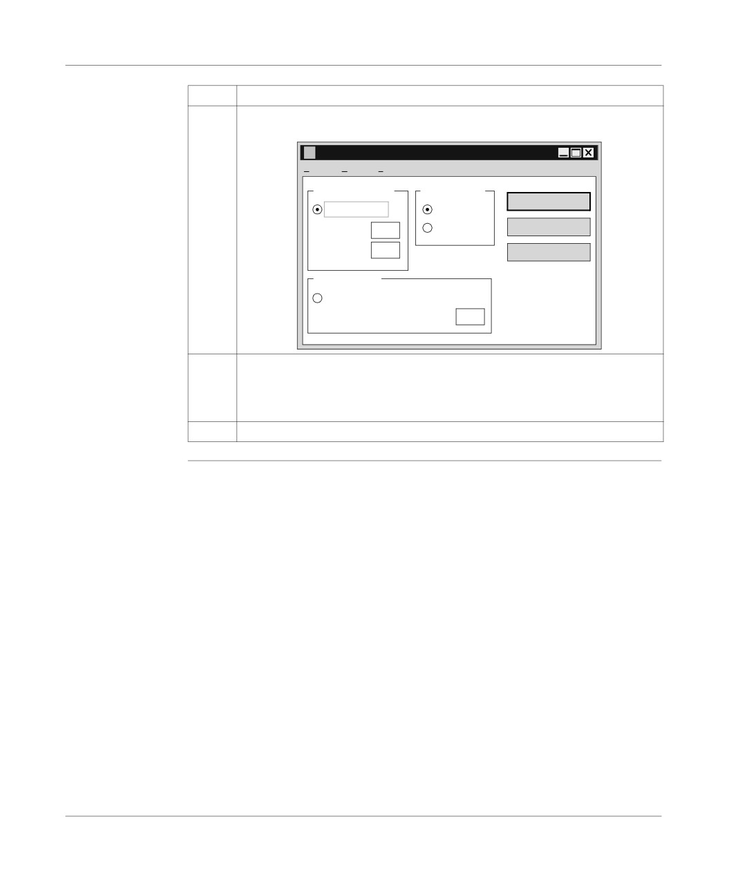
Click on the Configuration button.
Result: The dialog box below appears:
Configuration FIP FPC 10 - Par défaut
Fichier
Edition
?
Adresse FIPWAY
Instance driver
Enregistrer
Mode FIPWAY
FIP01
Réseau
0
FIP02
Ouvrir
Station
31
Par défaut
Adresse FIPIO
Mode FIPIO
Point de raccordement FIPIO
63
6
Configure:
l the FIPWAY operating mode and address,
l the driver instance,
l the FIPIO operating mode and connection point.
7
Click on Save.
401
Configuring the FIPWAY link
Configuring the terminal/FIPWAY link
At a Glance
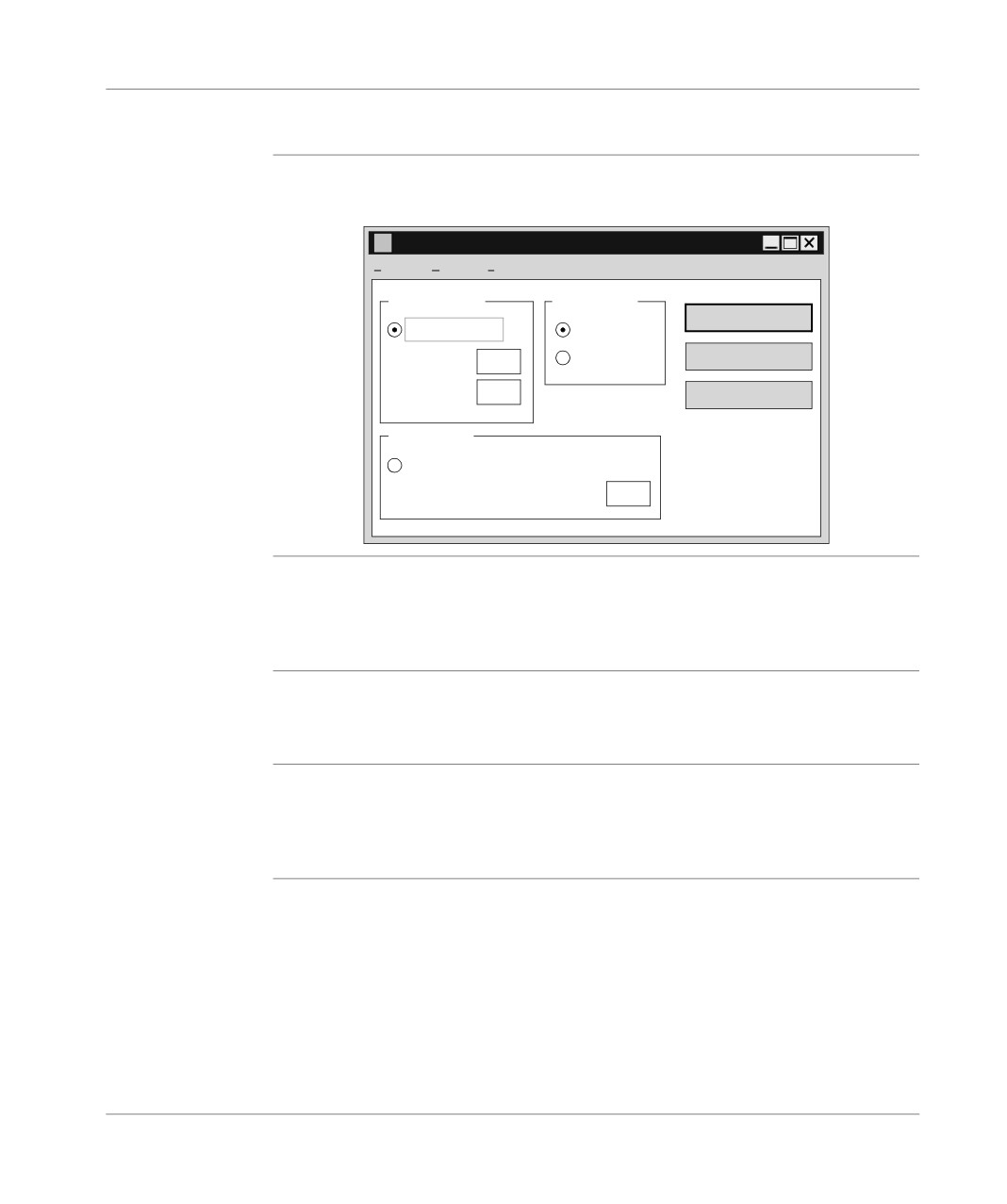
Various configuration parameters are available for the Fipway driver.
Main configuration screen:
FIP FPC 10 configuration - Default
File
Edit
?
FIPWAY address
Instance driver
Save
FIPWAY mode
FIP01
Network
0
FIP02
Open
Station
31
By default
FIPIO Address
FIPIO Mode
FIPIO connection point
63
Description of
This zone is used to select the FIPWAY operating mode (the driver is selected on
the FIPWAY
the FIPWAY network), as well as the network parameters and associated stations.
Address zone
Network gives the network number and Station gives the station number.
The default values are Network: 0 and Station: 31.
Description of
This zone is used to select the FIPIO operating mode (the driver is selected on a
the FIPIO
FIPIO bus) for the driver, as well as the associated Connection point The default
Address zone
connection point is 63.
Description of
This zone is used to select the driver instance to be modified. In most cases only
the Driver
one FPC10 card is installed on the computer for FIP communication. Thus, only the
instance zone
FIP01 driver instance will be used. However, if a second FPC10 card is installed, a
second driver instance FIP02 is necessary.
402
Configuring the FIPWAY link
Description of
Save button:
the Save button
is used to save the FIP FPC10 driver configuration.
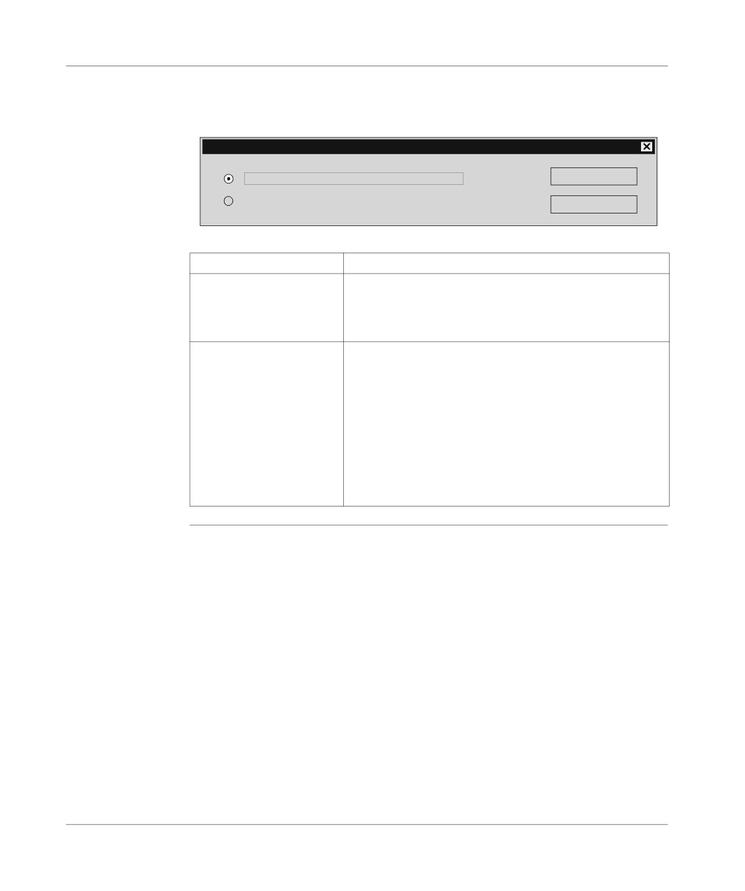
The save button makes the following dialog box appear:
FIP FPC10 Configuration - Save
Save a configuration file (DFPWAY.00?)
OK
Dynamically reinitialize the driver (in the memory)
Cancel
Elements and their functions:
Element
Function
Save in a configuration file
The FIP FPC10 driver configuration is saved on disk in a con-
(DFPWAY.00?)
figuration file (usually DFPWAY.001). This file is read by the
driver when the computer boots up. Modifications are taken
into account the next time the computer is booted up.
Dynamically reinitialize the
The configuration is written directly to the driver memory. Mod-
driver (in memory)
ifications are acknowledged immediately by the driver.
Dynamic reinitialization is impossible:
l if the driver is not loaded into the memory (at installation, for
example),
l if the modifications apply to parameters which cannot be
dynamically modified (for some advanced parameters for
example).
l if the driver is being used (if the PL7 is connected, for ex-
ample).
403
Configuring the FIPWAY link
Description of
The Open button:
the Open button
is used to read the FIP FPC10 driver configuration.
The Open button causes the following dialog box to appear:
FIP FPC10 Configuration - Open
Open a configuration file (DFPWAY.00?)
OK
Read the current driver configuration (from the memory).
Cancel
Elements and their functions:
Element
Function
Open a
The FIP FPC10 driver configuration is read in a configuration file on disk
configuration file
(usually DFPWAY.001). From this, you can view and modify the driver’s
(DFPWAY.00?)
initial configuration (read upon start-up).
Read current driv-
The configuration is read directly in the driver memory. From this you can
er configuration
view and modify the driver’s real time configuration. This selection is de-
(in memory).
activated if the driver is not loaded into the memory (at installation, for ex-
ample).
404
Configuring the FIPWAY link
Description of
The Default button:
the Default
is used to reinitialize the FIPWAY Address group values, FIPIO Address group val-
Button
ues and Driver instance group values to their default values, either:
l FIPWAY mode,
l Network 0 and Station 31,
l FIPIO connection point 63,
l FIP01 Instance.
405
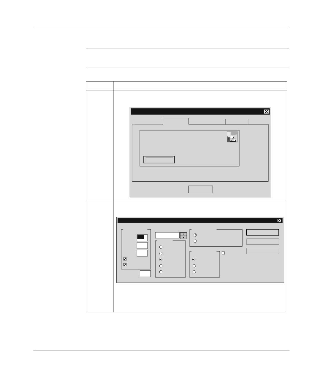
Configuring the FIPWAY link
Advanced Configuration
At a Glance
An advanced configuration is also available for the FIPWAY driver.
How to access
The following table describes how to access advanced configuration:
advanced
Step
Action
configuration for
the FIPWAY
1
From the configuration window click on File then select Advanced configura-
driver
tion, as shown in the following window:
Management properties of XWAY drivers
XWAY Manager
FPC10 Driver
UNITELWAY Driver
XWAY Test
FPW
FPC10 Driver V2.3 IE 12
Status driver 1: Non operational
Status driver 2: Non operational
Configuration
OK
2
Click on Advanced Configuration.
Result: the following window appears:
FIP FPC10 Configuration - Advanced
Buffers driver
I/O Address
Transfer mode
OK
210h
Programmed I/O mode
SBUF
16
Interrupt
DMA Mode
Cancel
RBUF
3
IRQ 3
DMA Channel
By default
ABUF
0
IRQ 5
WorldFIP
IBUF
IRQ 10
Channel 5
Page align
IRQ 11
Channel 6
PRUC
0
IRQ 15
Channel 7
The I/O Address fields, the Interrupt, Transfer Mode and DNA Channel zones
are used to adapt the driver configuration to the FPC10 card hardware config-
uration. Modify these values if you modify the hardware configuration of your
FPC10 card in relation to the factory configuration.
406