PL7 JUNIOR/PRO Operate modes manual (Operate modes manual eng V4.0) - page 9
Diagnostic functions
Diagnostics
Carry out the following steps:
procedure for
Step
Action
blocking errors
1
Access the debugging screen (Debug → Access the PLC debugging
screen). The ERR indicator flashes.
2
Click on the Diag button or select the PLC → Diagnostics command.
A dialog box provides the diagnostics details:
l click on Show source to position the cursor on the faulty module,
l click on Show Module call stack to ascertain the chronological sequence of calls
which led to the execution of the faulty module (from the most recent to the old-
est).
Diagnostics
These errors are indicated for each task.
procedure for
Carry out the following steps:
non-blocking
Step
Action
errors
1
In the PLC debugging screen, click on the Fault button which is associated with
the task.
2
Click on the Reset Fault Bit button (reset bits systems to 0) to confirm the
presence of the error on the different tasks (FAST, MAST, EVT).
Application
To refine the diagnostics, or in other words, to make this fault type blocking in order
monitoring
to isolate it, choose the monitoring option (Mon.) on the debugging bar or use the
Application monitoring command from the Debugmenu.
Then execute the diagnostics procedure for non-blocking errors.
325
Diagnostic functions
Module call stacks
Introduction
The Module call stack display function lets you know the chronological chain of
calls that have led to the execution of the faulty module (from the most recent to the
oldest), for a diagnostics error in a SR or a DFB type.
Accessing the
This function is accessible in diagnostics and in step by step program.
Module call stack
Click on Debug → Show module call stack.
The dialog box contains:
l the current task’s name. It is also possible to display the other tasks (only in di-
agnostics mode),
l the modules’ call list as well as the line/phrase which have led to the execution of
the faulty module (the first in the list is the top of the pile).
The View button allows you to view the module selected in the stack (or just double
click on the module). This function is also accessible by double clicking on the Liste-
Box.
326
Diagnostic functions
Diagnostics DFBs
Introduction
The diagnostics DFBs are accessible from PL7-Pro , and are used in the applica-
tions which run on TSX57/PCX57/PMX57 processors.
Diagnostics DFBs consist of:
l diagnostics application DFBs which are used to set up process monitoring via the
application program:
l PL7 equation monitoring,
l monitoring the reaction time of the process to a command,
l monitoring the inputs/outputs and the ASI bus,
l monitoring the safety conditions.
l working part control and diagnostics DFBs which are used to control and monitor
elements of the working part (EPOs):
l monitoring sensor information,
l monitoring actuator control requests,
l monitoring the duration of a movement,
l memorizing the minimum and maximum durations of a movement,
l learning the duration times of a movement,
l controlling an actuator.
At a Glance
The DFB diagnostics provided with PL7-Pro are:
DFB
Functions
EV_DIA
Monitoring the status of 2 bits without taking a time factor into account.
MV_DIA
Monitoring the status of two bits without taking a time factor into account,
with the option of monitoring a movement’s changes (change of bit status
within a given time period).
NEPO_DIA
Monitoring, checking and diagnostics for a working part element.
TEPO_DIA
IO_DIA
Diagnostics for all the I/O modules.
ASI_DIA
Diagnostics for an ASI inputs/output module.
ALRM_DIA
Interface with diagnostics buffer (error storage).
Descriptive form Every diagnostics DFB possesses a descriptive form describing the DFB function
and its parameters (inputs, outputs and public variables).
This form is accessed by double clicking on a DFB type in the application browser,
then by clicking on the Descriptive form tab in the DFB editor.
327
Diagnostic functions
Implementation of diagnostics DFB
Configuration of
To reserve a diagnostics buffer, carry out the following actions:
the diagnostics
Step:
Action:
buffer
1
Open the application’s Properties dialog box (Station directory in the applica-
tion browser).
2
Choose the Diagnostics tab.
3
Tick the Activate the diagnostics in the application box.
Registering
Before using a DFB in the application, carry out the following actions:
diagnostic DFBs
Step:
Action:
1
Import the binary DFB file (* .UFB) using Import binary from the contextual
menu within the PL7’s installation directory (example C:\PL7\PL7PRO33\DI-
AG).
2
Create a DFB instance (See Creating an instance from an application browser,
p. 265) in the PL7’s variables editor.
Programming
A Diagnostic DFB:
rule for
l must be executed in the MAST task for managing operate modes. So that it is
diagnostics
executed, it is necessary that:
DFBs
l the DFB is called (the program element to which it is assigned must be exe-
cuted)
l the ED input must be at 1.
l can be instanced in any program module (Section, SR) written in Ladder lan-
guage (LD), Structured Text (ST) or Instruction list (IL). It is strongly recommend-
ed that you only program the instance once,
l imposes a Label on the rung or the phrase containing it.
Information
System words and bits acquire information relative to the diagnostics:
system
Object
Information
%S101=1
Configured diagnostics buffer.
%S102=1
Full diagnostics buffer. If the diagnostics buffer cannot save an error, this error
is lost and the %S102 bit passes to 1.
%SW162
The number of errors in the diagnostics buffer.
328
Diagnostic functions
DFB diagnostics error messages
Display window
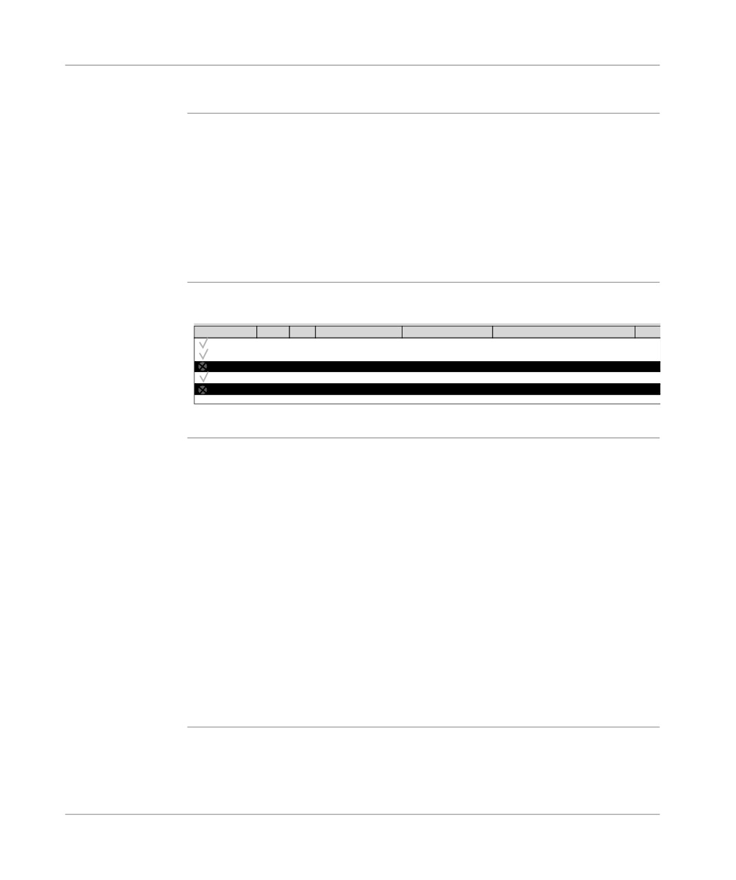
All the error messages appear in a window in the lower part of the runtime screens
for error
tool.
messages
The size of this window can be modified with the mouse, but its position is fixed.
However, it can be hidden.
It consists of a list of messages and has:
l a vertical scroll bar allowing you to view any obscured messages in the list,
l a horizontal scroll bar used to view the entire contents of a line.
Illustration of the
Integrated Viewer in PL7-Pro
Viewer
Acknowledgment Error Zone
Appearance: 5
Disappearance: 5
Message
Status
Without Ack…Ev_dia
0
01/03/2000 - 18:21:41
01/03/2000 - 18:21:46
Mixing time too short (< 5 s)
16#
Without Ack…Alrm_dia 0
01/03/2000 - 18:21:43
01/03/2000 - 18:22:16
Maximum mixer level reached: 25 liters
Not Ack... Alrm_dia
0
01/03/2000 - 18:22:16
01/03/2000 - 18:22:18
Maximum mixer level reached: 25 liters
Without Ack…Ev_dia
0
01/03/2000 - 18:22:25
01/03/2000 - 18:22:25
Mixing time too short (< 5 s)
16#
Not Ack... Alrm_dia
0
01/03/2000 - 18:22:05
01/03/2000 - 18:23:11
Maximum mixer level reached: 25 liters
A Diagnostics viewer is also available with the CCX17 V2.5.
Structure of error
Every line displayed in the Viewer corresponds to an error and contains the following
messages
information:
l the message status which is indicated by an icon plus text (the message having
to be acknowledged or not),
l the faulty DFB type,
l the geographical zone in which the source of the error is located,
l the time and date when the error appeared,
l the time and date when the error disappeared,
l the message associated with the error,
l the value of the word status at the time of the error.
The user can increase or decrease the size of the columns using the mouse. A col-
umn not displaying the information in its entirety ends in an ellipsis.
The width of each column is stored and retrieved while opening the runtime screens
tool.
329
Diagnostic functions
Error message
The number of messages it is possible to display is limited only by the size of the
display
memory buffer. When there is not enough memory, a message warns the user and
any messages of errors that have disappeared or have been acknowledged (if nec-
essary) are then deleted.
It is possible to modify the color of the messages and the blinking associated with
an acknowledged message.
In the viewer, it is possible to show only those messages which come from one or
more specific zones.
The list of messages can be sorted according to each field. To do this, simply click
on the column header containing the data on the basis of which the sort is to be car-
ried out.
A second click carries out the sort in opposite order.
By default, the error messages are inserted into the list in the chronological order in
which they appear.
Error message
Possible operations:
management
Operation
Implementation
Navigation
With the UP, Down, Page-Up, Page-Down, Home, and End keys.
Acknowledge-
By using the contextual menu having selected the corresponding item.
ment
Several messages can be acknowledged at the same time.
After an acknowledgment, an order is sent to the PLC.
The acknowledgment can come from another viewer, in which case the runt-
ime screens tool is alerted and the message is displayed as acknowledged.
Deletion
By using the contextual menu having selected the corresponding item or by us-
ing the Delete key.
Only messages that have disappeared and been acknowledged (if necessary)
are deleted.
Properties
By using the contextual menu, or the Enter key.
The following information is displayed:
l the name and type of the faulty DFB instance,
l the program address containing the faulty DFB instance,
l the associated text and status bits.
330
Diagnostic functions
Error message
Archiving is used to create a log file. The activation and the location of this file are
archiving
configured in a window that can be accessed using the Service/Configure/Viewer
tab command.
It is possible to modify the directory in which the archive file is located. By default,
it is kept inC:\PL7USER\NameAppli.HIS.
This file is in ASCII format, so it is easy to import it into a text editor or a spreadsheet.
To stop the file from becoming too large, it is renamed in NameAppli.BAK every
1000 saves and a new file is created with its source name.
WARNING
If a NameAppli.BAK file already exists, it is deleted without warning.
Failure to observe this precaution can result in severe injury or
equipment damage.
Error message
Messages can be customized for every diagnostics DFB instance.
customization
The modification is made via the DFB variable editor menu and the new message is
entered into the comment zone.
Note:
The diagnostics DFBs that do not support error message customization are IO_IA
and ASI_DIA.
331
Documentation
16
Presentation
What’s in this
This chapter describes how to create the documentation file for the application.
chapter
What’s in this
This Chapter contains the following Maps:
Chapter?
Topic
Page
Contents of documentation file
334
Documentation: application documentation file
337
333
Documentation
Contents of documentation file
At a Glance
The documentation file of an application contains the following different headings:
l title page,
l contents,
l configuration,
l function view,
l program,
l DFB types,
l cross references,
l animation table,
l variables,
l cartridges.
Description of
Title page:
the title page and
this heading gives the name of the designer and the name of the project.
the contents
Contents:
the contents table is created automatically by the software according to the selected
options.
Description of
This heading has two sub-headings:
the configuration
l hardware configuration,
heading
l software configuration.
Hardware configuration:
rack configuration, module parameters.
This sub-heading allows you to print the PLC configuration as well as the different
parameters of the input/output modules.
Software configuration:
this sub-heading allows you to print the application software configuration.
Description of
This heading gives the function view contents list.
the Function
View heading
334
Documentation
Description of
Choosing this heading automatically selects the existing modules in the application.
the program
For each language LD, IL and ST select printing in symbol or address format.
heading
The selected mode applies to all modules in the same language.
The "With Variables Used" option allows you to print the list of the variables used
after each rung or phrase.
Several sub-headings are available:
l application structure,
l MAST task,
l FAST task,
l event task.
Application structure:
this heading is used to print the application software structure as well as the tree
structure subroutine calls.
MAST Task :
this sub-heading is itself built up of sections (as well as PRL/CHART/POST modules
if there is a GR7 section) and subroutines.
FAST Task :
this sub-heading is also built up of sections and subroutines.
All of these headings are used to print the contents of the different sections that con-
stitute the program.
Description of
The following details are given for each DFB type:
the DFB Type
l the properties,
heading
l the descriptive form,
l the interface and public variables,
l the code (except for Schneider diagnostics DFBs),
l the private variables.
335
Documentation
Description of
Cross references:
the cross
this heading allows you to print the list or lists of variable cross references.
references,
animation tables
Animation table:
and variables
this heading allows you to print the different animation tables along with the address-
headings
es, the symbols, the types and the kind.
List of variables :
this heading is used to print the list or lists of variables and their parameters.
Description of
Select this heading to create a footer at the bottom of the documentation page:
the footer
l the blank fields can be filled in by the user,
heading
l the shaded fields are filled in automatically.
336
Documentation
Documentation: application documentation file
Accessing the
To access a documentation file, double click on the documentation file icon in the
application
structure view of the application browser, a documentation window then displays
documentation
the various components of the application documentation file.
file
Components of
Each element of the documentation file can be included or excluded by using the
the application
contextual menu: by right clicking.
documentation
The elements included in the documentation file are marked with a red square.
file
To build the file carry out the following actions:
Step
Action
1
Select each element to be included or excluded in the file using the Include
heading or Exclude heading contextual menus or select Edit → Exclude
heading from the menu.
2
Set the parameters for the various elements: Program, DFB type, Cross refer-
ences, Variables, Footer.
3
Select the Build contextual menu via the general documentation file icon or se-
lect Edit → Build from the menu.
Setting the
Various parameter settings are available for the documentation file:
documentation
l setting the footer parameters,
file parameters
l setting the variable sorting parameters,
l setting the cross reference sorting parameters,
l setting the program printing parameters,
l setting the DFB printing parameters.
Setting the footer parameters
Click on the footer icon in the documentation window and select the Parameters
contextual menu.
l the blank fields can be filled in by the user,
l the shaded fields are filled in automatically.
337
Documentation
Setting the variable sorting parameters
Carry out the following actions:
Step
Action
1
Click on the variables icon in the documentation window and select the Pa-
rameters contextual menu.
2
Select the variable sorting order: ascending order of symbols, ascending order
of addresses or both.
Setting the cross reference sorting parameters
Carry out the following actions:
Step
Action
1
Click on the Cross references icon in the documentation window and select
the Parameters contextual menu.
2
Select the variable sorting order: ascending order of symbols, ascending order
of addresses or both.
Setting the program printing parameters
Click on the Program icon in the documentation window and select the Parame-
ters contextual menu to access the different tabs:
l Instruction List tab
Select printing in either symbol or address format.
Check the With variables used box to also print the variables of the program
module.
l Structured Text tab
Select printing in either symbol or address format.
Check the With variables used box to also print the variables of the program
module.
l Ladder Language tab
Check the Long Text box to print all the symbols.
Select printing in symbol and/or address format.
Check the With variables used box to also print the variables of the program
module.
Setting the DFB printing parameters
Carry out the following actions:
Step
Action
1
Click on the DFB type icon in the documentation window and select the con-
textual Parametersmenu.
2
Select the components to be printed.
338
Documentation
Printing the
documentation
Documentation file print setup
file
Carry out the following actions:
Step
Action
1
Select the File → Print Setup menu.
l if a printer is already configured in the Windows Print Manager as a default
printer, it is shown in the dialog box,
l if several printers have been declared in the Windows Print Manager, select
the required printer from the list.
2
Configure the printer by clicking on Configuration.
Note: It is necessary to rebuild the documentation file if the printer is changed.
Print Preview
Carry out the following actions:
Step
Action
1
Select the element to be displayed from the documentation file.
2
Select the Viewcontextual menu (right click).
Printing the documentation file
Two printing options:
l printing the documentation file,
l printing a element of the documentation file.
Printing the documentation file
Step
Action
1
Click on the program icon in the documentation window.
2
Select Print from the contextual menu or click on the printer icon in the task
bar.
Printing an element of the documentation file
Step
Action
1
Click on icon of the element to be printed in the documentation window.
2
Select Print from the contextual menu or click on the printer icon in the task
bar.
Note: It is possible to interrupt printing by clicking on Cancel.
339
Documentation
340
Import/Export
17
Introduction
Subject of this
This chapter describes :
chapter
l The application’s source files.
l The export/import of the application’s source files.
What’s in this
This Chapter contains the following Maps:
Chapter?
Topic
Page
General points on import/export
343
Import/Export source files
344
Exporting a Section , a Subroutine, an Event
351
Importing a Grafcet/Ladder/List/Structured text section
353
Exporting an LD, IL, ST, Grafcet source file
354
Importing an LD, IL, ST, Grafcet source file.
355
Exporting variables
357
Importing variables
358
Importing/Exporting variables in EXCEL format
360
Exporting a functional module
362
Importing a functional module
364
Importing a functional module using the wizard
366
Exporting animation table(s)
369
Importing animation table(s)
371
Export of runtime screens
373
Import of runtime screens
375
Export of a DFB type
376
Importing a DFB type
378
Exporting an application
380
341
Import/Export
Topic
Page
Importing an application
382
Exporting an application in FNES format (Input/Output Neutral File)
384
Importing an application in FNES format
385
342
Import/Export
General points on import/export
Introduction
Import/Export functions for the PLC TSX 37 or TSX 57 applications allow you:
l to insert or to duplicate all or part of IL, LD, ST, Grafcet program module.
l to insert an IL, LD or ST section into a task (MAST, FAST, EVT...).
l to insert a DFB type into the list of DFBs.
l to insert symbolized variables in the table of variables.
File types
The following file types can be imported or exported:
l LD source denoted by *.LD.
l IL source denoted by *.IL.
l ST source denoted by *.ST.
l Grafcet source denoted by *.GR7.
l Symbols source denoted by *.SCY.
l DFB type source denoted by *.DFB.
l DFB type binary denoted by: *.UFB.
l Application source denoted by *.FEF.
Notes:
File source code is 8 bit ASCII conforming to ISO standard 8859-1.
The input of code is possible directly using WINDOWS compatible editors, such
as Word in text format (*.TXT).
The code of a DFB type binary is not accessible (encrypted).
Possible
File/Export supports the export of:
commands
l All or part of a LD, IL, ST or Grafcet program module.
l All or part of the symbols table.
l A DFB type.
File/Import supports the import of:
l An LD, IL, ST, G7 file.
l A DFB type.
l A symbol source.
Notes:
In order to select the directory containing the applicationsource files, use the com-
mand Options/Customize. (The file PL7.INI contains the pathname for the source
files). The source directory becomes the current directory for import/export.
343
Import/Export
Import/Export source files
General points
A source file is composed of a minimum of three blocks of information structured in
lines of a maximum 1024 characters, terminating in one or two end of entry charac-
ters.
A block is identified by its name between [ ].
The end of the source file is identified by the "[EOF]" (End Of File) character string.
Description of
A file is made up of the following blocks:
the blocks
l A [HEADER] block, containing general information (Date, Manufacturer’s Name).
l The [APPLICATION] block identifies:
l The name of the source application.
l Date of creation.
l Version.
l Comments.
l The [VENDOR] block describes the configuration (number of timers, counters, in-
ternal bits, etc.).
l The [SOURCE UNIT] block for the program modules contains:
l LD code for *.LD files.
l IL code for *.IL files.
l ST code for *.ST files.
l GR7 code for *.GR7 files.
l Properties, parameters and code for DFB files (*.DFB).
l The [DATA UNIT] block for the symbols files contains:
l application variables (file denoted by "*.SCY").
344
Import/Export
LD source file
Header Block
[HEADER]
DATE = date #1999-12-10
STANDARD = ’PLCopen v0.1 1993’
SENDER = ’Schneider Automation S.A. PL7 PRO V3.4’
Application Block
[APPLICATION]
NAME = ’MACHINE_DOSAGE’
DATE = date_and_time#1999-12-10-14:52:06
VERSION = ’0.125’
Source Unit Block
[SOURCE_UNIT]
SU_TYPE = PROG
NAME = ’MAST_MAIN’
LANGUAGE = LD
BODY =
ADDRESS = MAST MAIN
PROGRAM
RUNG (*Mixing timer*)
P_CONTACT(%M17),BLOCK(%TM0),H_LINK(7),COIL(%M15);
EMPTY_LINE;EMPTY_LINE;
END_RUNG
RUNG
(*Management of mixer emptying*)
OPEN_CONTACT(%X1.0),H_LINK,P_CONTACT(%M200),
OPEN_CONTACT(%M16),H_LINK(3),OPERATE DEC %MD12 END_BLOCK;
END_RUNG
END_PROGRAM
[EOF]
345
Import/Export
IL source file
Header Block
[HEADER]
DATE = date #1999-10-10
STANDARD = ’PLCopen v0.1 1993’
SENDER = ’Schneider Automation S.A. PL7 PRO V3.4’
Application Block
[APPLICATION]
NAME = ’MOP5’
DATE = date_and_time#1999-10-10-14:52:06
VERSION = ’0.125’
Source Unit Block
[SOURCE_UNIT]
SU_TYPE = PROG
NAME = ’MAST_SR1’
LANGUAGE = IL
BODY =
ADDRESS = MAST SR1
PROGRAM(*PHRASE*)(* *) LDN %M0 ST
%M1
LD
%M2 ST
%M3
(*END_PHRASE*)
END_PROGRAM
[EOF]
346
Import/Export
ST source file
Header Block
[HEADER]
DATE = date #1999-08-10
STANDARD = ’PLCopen v0.1 1993’
SENDER = ’Schneider Automation S.A. PL7 PRO V3.4’
Application Block
[APPLICATION]
NAME = ’MOP6’
DATE = date_and_time#1999-08-10-14:52:06
VERSION = ’0.125’
Source Unit Block
[SOURCE_UNIT]
SU_TYPE = PROG
NAME = ’FAST_MAIN’
LANGUAGE = ST
BODY =
ADDRESS = FAST MAIN
PROGRAM(*PHRASE*)(*INIT*)%L1:
IF %MW0=%MWW1
THEN %SR1;
END_IF;
(*END_PHRASE*)
END_PROGRAM
[EOF]
347
Import/Export
G7 source file
Header Block
[HEADER]
DATE = date #1999-06-10
STANDARD = ’PLCopen v0.1 1993’
SENDER = ’Schneider Automation S.A. PL7 PRO V3.4’
Application Block
[APPLICATION]
NAME = ’MOP7’
DATE = date_and_time#1999-06-10-14:52:06
VERSION = ’0.125’
Source Unit Block
[SOURCE_UNIT]
SU_TYPE = PROG
NAME = ’Sequential’
LANGUAGE = OTHERS
BODY =
ADDRESS = MAST Chart
PROG_LANGAGE = GR7VAR_GLOBAL
END_VAR
PROGRAMMAST’Chart’
NB_PAGES = 8
PAGE 0
INITIAL_STEP 0 AT (C 4,L 3) :
ACTION (N1,LD) :
RUNG EMPTY_LINE;OPEN_CONTACT(%M8),H_LINK(9),
COIL(%M10);
END_RUNG
END_ACTION
END_STEP
TRANSITION (*TOP*) (LD) AT (C 4,L 4) :
RUNG OPEN_CONTACT(%M1),H_LINK(9),
HASH_COIL;
END_RUNG
END_TRANSITION
T_S_OR_LINK FROM (C 4,L 4) TO (C 4,L 3) := [H_LINK FROM (C 4,L 4)
TO (C 5,L 4), V_LINK FROM (C 5,L 4) TO (C 5,L 2),
H_LINK FROM (C 5,L 2) TO (C 4,L 2)]END_PAGEPAGE 1
END_PAGE
348
Import/Export
Source Unit Block (next)
PAGE 2
END_PAGE
PAGE 3
END_PAGE
PAGE 4
END_PAGE
PAGE 5
END_PAGE
PAGE 6
END_PAGE
PAGE 7
END_PAGE
END_PROGRAM
[EOF]
349
Import/Export
Symbols source
Header Block
file
[HEADER]
DATE = date #1999-12-10
STANDARD = ’PLCopen v0.1 1993’
SENDER = ’Schneider Automation S.A. PL7 PRO V3.4’
Application Block
[APPLICATION]
NAME = ’MOTOR’
DATE = date_and_time#1998-12-02-14:52:06
VERSION = ’0.125’
Data Unit Block
[DATA_UNIT]
DA_TYPE =
LOCATION =
NAME =
BODY =
VAR_GLOBAL
Surv_niv_malax : Alrm_dia (*Maximum mixer level reached: 25 liters*);
Gest_prod_silo_a : Cpt_remplissage;Gest_prod_silo_c :
Cpt_remplissage;Gest_prod_silo_b : Cpt_remplissage;
Gest_prod_melangeur : Cpt_remplissage;Surv_malax :
Ev_dia (*Mixing time too short (<5secs)*);
Vidange_cuve : Simul_vidange;Dcy AT %M0 : EBOOL
(*Start cycle*);Evt_1 AT %M1 : EBOOL
(*Silo A valve (=0 closed =1 open)*); Evt_2 AT %M2 : EBOOL
(*Silo B valve (=0 closed =1 open)*); Evt_3 AT %M3 : EBOOL
(*Silo C valve (=0 closed =1 open)*); Evt_4 AT %M4 : EBOOL
(*Hopper B1 valve (=0 closed =1 open)*); Evt_5 AT %M5 : EBOOL
(*Hopper B2 valve (=0 closed =1 open)*); Evt_6 AT %M6 : EBOOL
(*Mixer valve (=0 closed =1 open)*);
END_VAR
[EOF]
350
Import/Export
Exporting a Section , a Subroutine, an Event
Introduction
The Export function can be accessed in local mode and in connected mode, with
the PLC in Stop mode.
It supports export of:
l all or part of a program module from within a language editor (LD, IL, ST, Grafcet),
l a whole section, a program module from within the application browser.
Exporting from
Carry out the following actions:
within an editor
Step
Action
1
Open the section (LD, IL, ST orGrafcet).
2
Select the part of the program to be exported (if nothing is selected, the whole
module is exported).
For Grafcet, select either:
l the whole module (default),
l the current page (the one where the cursor is),
l from page x to page y inclusive, between values 0 and 7.
3
Select the command File/Export.
4
Select the disk and/or the directory where the file is to be saved using the pull-
down menu In.
5
Enter a file name in the field Name.
6
Confirm with Save.
Exporting from
Carry out the following actions:
within the
Step
Action
application
1
Left mouse click on the Section or the Module to be exported or move the cur-
browser
sor using the arrow keys.
2
Using the contextual menu or the File menu or the keys Shift+F10 select the
command Export
3
Select the disk and/or the directory where the file is to be saved.
4
Enter a file name in the field Name.
5
Confirm with Save.
351
Import/Export
Notes
During export, the message "Processing (Esc to cancel):1" is displayed in the sta-
tus bar.
Pressing Esc followed by confirmation stops the export and the source file is not cre-
ated.
Errors
The only error that can arise is insufficient disk space available. If this happens, an
error message is displayed.
The generation of the source file in progress is aborted.
352
Import/Export
Importing a Grafcet/Ladder/List/Structured text section
Importing a
See: Creating or importing a Grafcet section, p. 107.
Grafcet section
Importing a Lad-
See: Creating or importing an LD, IL, ST section, p. 105.
der/List/Struc-
tured text section
353
Import/Export
Exporting an LD, IL, ST, Grafcet source file
Introduction
The Export function can be accessed off-line or on-line, PLC at Stop).
It is used to export:
l all or part of a program module from a language editor (LD, IL, ST, Grafcet),
l a complete section or program module from the application browser.
Exporting from
Carry out the following:
an editor
Step
Action
1
Open the (SR, EVT, PRL, POST) section or module.
2
Select the part of the program to be exported (if nothing is selected, all the
module is exported).
With Grafcet:
Select either:
l the whole module (by default),
l the current page (the one the cursor is on),
l from page x to page y with x, y between 0 and 7.
3
Select the command File/Export.
4
Select the disk and/or directory where the file is to be saved using the scrollable
menu In.
5
Enter a filename in the field Name.
6
Confirm with Save.
Exporting from
Carry out the following:
an application
Step
Action
browser
1
Right click on the section or module to be exported or select with the arrow
keys and then press (Shift + F10).
2
Select the command Export.
3
Select the disk and/or directory where the file is to be saved.
4
Enter the filename in the field Name.
5
Confirm with Save.
Errors
The only error that can occur with an Export is lack of available disk space; in this
case an error message is displayed.
354
Import/Export
Importing an LD, IL, ST, Grafcet source file.
Introduction
The Import function can be accessed in local mode and in connected mode, with
the PLC in Stop mode.
It supports import of:
l A source file into a section (empty or already programmed) from a language ed-
itor,
l A section or a module from the application browser.
Importing from
Carry out the following actions:
within an editor
Step
Action
1
Open the section, or the module (SR, EVT, PRL, POST).
2
Put the cursor in the editor in the position where you want to insert the code.
3
From the File menu select the command Import.
4
Select the source file relating to the section to be imported.
5
Carry out any necessary corrections (label %Li, Step number…).
6
Confirm the import with Enter or select the command Edit/Accept (CTRL+W)
or click on the icon
Importing from
l Importing a Section (See Creating or importing an LD, IL, ST section, p. 105),
within the
l Importing an SR (See Creating or importing a subroutine (SR), p. 109),
application
l Importing an event (See Creating or importing an event, p. 110),
browser
l Importing a Grafcet source:
l This applies to all or part of the chart (CHART module, Step-Macro).
l It can be carried out from any page referenced by the position of the cursor.
The imported pages replace the current pages.
l If Grafcet objects (step activity bits, step time bits) are referenced in the appli-
cation, a message informs the user.
l At the end of the import, the cursor is positioned on the last defined return key
symbol or on the page which follows the last imported page.
355
Import/Export
l Special cases:
-If eight pages are read, the cursor remains on page seven.
-If the user aborts the import part way through, the cursor is positioned on the
first page of the import.
-If the contents of a page are incorrect, the editor displays the page in error
with the correction functions for the page and the look-up functions for the pag-
es already imported.
-The contents of a Macro-Step cannot be imported into the CHART and vice
versa.
Notes
During import, the message "Processing (Esc to cancel):1" is displayed in the sta-
tus bar.
Pressing Esc followed by confirmation deletes the code already inserted.
Errors
Two types of error are possible:
l Non blocking errors, in this case:
l The corresponding editor is launched on the phrase, the contacts network or
the chart containing the anomaly.
l The user can correct or abort the import. If the correction is carried out the im-
port continues.
l Blocking error (source file modified in the editor), in this case:
l The user can only abort the import, the import is interrupted.
l The user must remedy the cause and restart the import procedure.
Note:
If an object is not configured, accessing configuration to remedy the problem is pos-
sible, after validation the import can continue.
356
Import/Export
Exporting variables
Functionality
The Export variables function can be accessed in local mode and in connected
mode, with the PLC in Stop mode.
Procedure
Carry out the following actions:
Step
Action
1
Open the variables editor from the application browser by double clicking with
the left mouse button on one of the data families or by using the keys Shift+F10
or via the contextual menu command Open.
2
From the File menu select the command Export.
3
Select the disk and/or the directory where the file is to be saved using the pull-
down menu In.
4
Enter a file name in the field Name.
5
Select the export mode.
l All types: all the database entries are exported,
l Current type: only the data relating to the current display type is processed.
6
Confirm withSave.
Notes:
During the processing period the message "Processing object (Escape to can-
cel):xx" (number of the element being processed) is displayed in the status bar.
Pressing Esc followed by confirmation stops the processing and no source file is
created.
Errors
The only error that can arise is insufficient disk space available. If this happens, an
error message is displayed.
The generation of the source file in progress is aborted.
357
Import/Export
Importing variables
Introduction
The Import variables function can be accessed in local mode and in connected
mode, with the PLC in Stop mode.
It supports insertion of a data file into the application (%M, %S, %K, %X, E/S, SFB,
EFB, DFB) from the variables editor.
Managing
There are three kinds of conflicts:
conflicts
l Address conflict:
l The symbol to be read already exists in the symbols database, but it repre-
sents a different address
l Symbol conflict:
l The address to be read is already represented in the symbols database, but
by a different symbol.
l Comments conflict:
l The address to be read is already represented in the symbols database with
the same symbol, but the 2 comments which are associated with them are dif-
ferent.
Three modes of operation allow you to manage these situations:
l Overwrite mode:
l Priority is given to the contents of the source file.
l Do not overwrite mode:
l Priority is given to the contents of the symbols database.
l Dialog mode:
l The user chooses the priority in relation to the conflict displayed.
Procedure
Carry out the following actions:
Step
Action
1
Open the variables editor from the application browser by double clicking with
the left mouse button on one of the data families, or via the Contextual menu
select the command Open.
2
Select the command File/Import.
3
Select the file .SCY to be imported.
4
Select the operation mode:
l Overwrite,
l Do not overwrite,
l Dialog.
5
Accept with Open.
Notes:
358
Import/Export
During the processing period the message "Processing object (Escape to can-
cel):xx" with xx the number of the element being processed is displayed in the sta-
tus bar.
Pressing Esc causes the abort after restoring the current variable, the variables al-
ready restored are kept.
Errors
On detecting collisions in the database the user can either:
l Keep the contents of the database.
l Overwrite the variable with that from the file being restored.
l Abort the import.
359
Import/Export
Importing/Exporting variables in EXCEL format
Introduction
This function concerns the unitary import/export of variables.
It is possible to import/export application variables using a format which is compati-
ble withEXCEL.
This makes it easier to work with and create source files, using EXCEL.
General points
TXT is the chosen format, using tabs as separators. Provision is made for this save
format in the EXCEL tool.
However, when reading these files in EXCEL, it must be indicated to EXCEL that the
tabulation character is to be interpreted as a separator (standard principles of file im-
port into EXCEL).
How to export
Carry out the following steps:
variables in
Step
Action
EXCEL format
1
In the Structure View of the Application Browser double click on the Vari-
ablesdirectory.
2
Right click (contextual menu) on one of the variable items.
3
Click on open.
Result: a variables window appears.
4
Select File → Export.
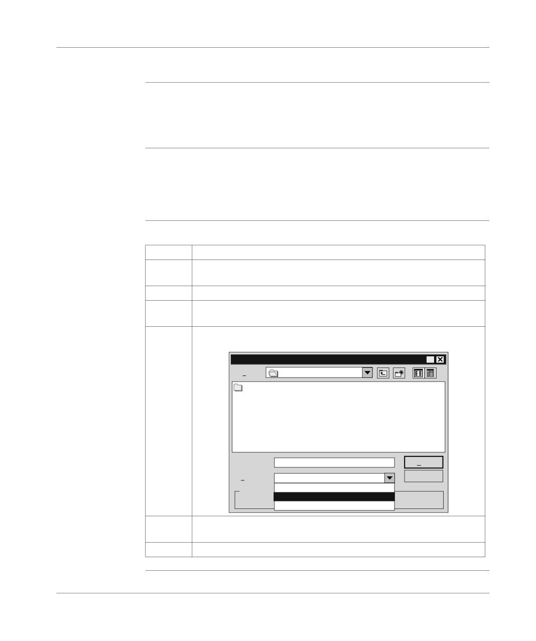
Result: the following window appears.
Export
?
In:
Pl7user
FIRST screen
Name:
Save
Type:
Text (separator: tabulations *TXT)
Cancel
Source Symbols (*.SCY)
Export mode
Text (separator: tabulation *TXT)
types
All (*.*)
5
Choose the export destination directory and in the Type field select: "Text
(separator: tabulations *TXT)".
6
Name the file and click on Save.
360
Import/Export
How to import
Carry out the following steps:
variables in
Step
Action
EXCEL format
1
In the Structure View of the Application Browser double click on the Vari-
ablesdirectory.
2
Right click (contextual menu) on one of the variable items.
3
Click on open.
Result: a variables window appears.
4
Select File → Import.
Result: the following window appears.
Import
?
Find:
Pl7user
test. TXT
Name:
test. TXT
Open
Type:
Text (separator: tabulation *TXT)
Cancel
Source Symbols (*.SCY)
Import mode
Text (separator: tabulation *TXT)
Ove
All (*.*)
Dialog
5
Choose the directory from which the import should be carried out and in the
Type field select: "Text (separator: tabulations *TXT)".
6
Select the file and click on Save.
361
Import/Export
Exporting a functional module
At a Glance
Exporting a functional module involves:
l exporting the sections, events and Grafcet modules which make up the functional
module,
l and exporting the functional sub-modules which make up the functional module.
The short name and the function name are exported and then restored at the time
of import.
The Export functional module function can be accessed in offline and online mode,
with the PLC in Stop mode.
WARNING
When the functional module has one or more DFB instances:
The receiver application must contain the DFB type(s) corresponding to
the functional module instances, in order to be able to subsequently im-
port the functional module.
Failure to observe this precaution can result in severe injury or
equipment damage.
Procedure
Carry out the following actions:
Step
Action
1
Left click on the module to be exported or position the cursor over it using the
arrow keys.
2
Using the contextual menu or the File menu or using the keys Shift+F10 select
the commandExport.
3
Select the disk and/or directory where the file is to be saved (PL7user is the
default directory).
4
Enter a file name in the Name field (the source file is of the type *.FM)
5
Confirm with Save.
Notes:
Exporting a functional module is prohibited if an associated section, event or Grafcet
module is being modified.
362
Import/Export
Exporting a
Exporting a functional module creates a directory NameDir.FM, containing:
functional
l a source file NomMod.FM,
module with
l an ECREXP directory where the tree structure dedicated to the runtime screens
runtime
is located.
screen(s)
The export procedure is identical to that described above.
Exporting a
The source file NomMod.FM contains the source of each animation table contained
functional
in the functional module.
module with
animation
Exporting the functional module is authorized if no animation table is being modified.
table(s)
The Export procedure is identical to that described above.
363
Import/Export
Importing a functional module
At a Glance
Importing a functional module is the same as creating a module by:
l importing the sections, events and Grafcet modules making up the module,
l and importing the functional submodules making up the functional module.
The short name and the function name are exported and then restored at the time
of import.
If a section, event, Grafcet module, or functional sub-module making up the import-
ed functional module already exists with the same name, the software allows you to
enter a new name.
The Import function can be accessed in offline and online mode, with the PLC in
Stop mode.
Two import procedures are available:
l import without reassignment,
l import with reassignment, which allows you to make changes before starting the
import.
WARNING
When the functional module has one or more DFB instances:
The receiver application must contain the DFB type(s) corresponding to
the functional module instances, in order to be able to import the func-
tional module.
Failure to observe this precaution can result in severe injury or
equipment damage.
Procedure for
Carry out the following actions:
importing
Step
Action
without
reassignment
1
Left click on the destination directory (station or functional module directory) or
position the cursor over it using the arrow keys.
2
Using the Contextual menu, the File menu or the Shift+F10 keys select the
Import command.
3
Select the source file (*.FM) to be imported.
4
Confirm with Open
364
Import/Export
Note:
As only one Grafcet section is allowed in the MAST task, importing a module con-
taining a Grafcet section is prohibited if a Grafcet section already exists.
Procedure for
Carry out the following actions:
importing with
Step
Action
reassignment
1
Left click on the destination directory (station or functional module directory) or
position the cursor over it using the arrow keys.
2
Using the Contextual menu, the File menu or the Shift+F10 keys select the
Import command.
3
Select the source file (*.FM) to be imported.
4
Check the box Open with wizard.
5
Confirm with Open.
Note:
For more information on the wizard, see "Importing a functional module using the
wizard" (See Importing a functional module using the wizard, p. 366).
Importing a
The contents of the file NAME.FM containing the source of each animation table in
functional
addition to the information linked to the functional module is imported.
module with
animation
The possible conflicts are dealt with in the section Importing animation table(s), p.
table(s)
371.
If the procedure with reassignment is selected then:
l it is impossible to reassign a variable which is only present in an animation table,
l reassigned variables are also reassigned for the animation tables which contain
them.
Importing a
If the procedure with reassignment is selected then:
functional
l it is impossible to reassign a variable which is only present in a runtime screen,
module with
l reassigned variables are also reassigned for the runtime screens which contain
runtime
them.
screen(s)
365