PL7 JUNIOR/PRO Operate modes manual (Operate modes manual eng V4.0) - page 7
Function modules
11
Presentation
Object
This chapter describes the function modules.
What’s in this
This Chapter contains the following Maps:
Chapter?
Topic
Page
Function modules
246
Properties of a function module
247
Creating a functional module
248
Programming a functional module
249
Debugging a functional module
250
Detaching/Deleting a functional module
251
Export of a functional module
254
Importing a functional module
255
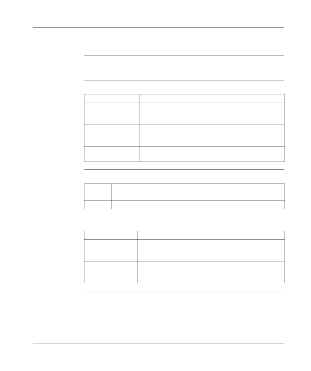
Creating, deleting, moving, dragging and dropping an animation table in a
256
functional module
245
Function modules
Function modules
Definition
l A function module is a group of program elements )sections, sub-programs, mac-
ro steps, animation tables, operating screens…) used to carry out a PL7 function.
l A function module can itself be broken down into lower level function modules. In
relation to the principle function these modules assume one or more PL7 sub-
functions.
Attributes of a
A function module is composed of:
function module l a short name : 8 characters (e.g.: TR371), this name must be unique in the ap-
plication,
l a long name : 16 characters (e.g.: Continue/Withdraw for BT371),
l function sub-modules : these are lower level function modules,
l associated program code modules. sections, events, grafcet module (Prl,
Chart, macro steps Xm, Post),
l a descriptive form (with no maximum number of characters), stored in the PL7,
l associated animation tables,
l operating screens.
246
Function modules
Properties of a function module
Properties to be
List of different properties to be defined:
defined
l the short name: composed of 8 characters (e.g.: TR371), this name must be
unique in the application,
l the optional long name composed of 16 characters (e.g.: Continue/Withdraw for
BT371),
l the optional descriptive form stored in the PL7.
How to display or
Carry out the following steps:
modify the
Step
Action
properties
1
Right click on the function module, in the Function view of the Application
browser.
2
Click on Properties.
2
Carry out the modifications.
3
Click on OK.
Note: The Apply button confirms the modifications without closing the window.
247
Function modules
Creating a functional module
At a Glance
A functional module can be created offline, with the PLC in Stop or in Run.
It can be created at Station level or at the level of each existing functional module.
How to create a
Carry out the following actions:
functional
Step
Action
module
1
From the functional view, right click on the Station directory, or on the directory
of an existing functional module, or place the cursor on this directory and then
press Shift+F10.
2
Select Create.
3
Fill in the short name, the long name, the comment and confirm with OK.
How to create a
Carry out the following actions:
lower level
Step
Action
functional
1
Right click on the "higher level" module or position the cursor on it and press
module
Shift + F10.
2
Select Create.
3
Fill in the short name, the long name, the comment and confirm with OK.
Moving a
A functional module can be moved offline, with the PLC in Stop or in Run (this has
functional
no effect on the execution of the application). The movement only corresponds to a
module
modification in the functional architecture of the application (a module is linked di-
rectly to theStation directory level or to another functional module).
To move a functional module:
Step
Action
1
Left click (keeping the button held down) on the module to be moved,
2
Move the module to the desired position.
248
Function modules
Programming a functional module
Introduction to
A functional module has aprogram directory which may contain:
programming a
l LD, ST, or IL sections,
functional
l events,
module
l of a Chart, Prl, Post, Macro-Steps module.
Several scenarios are possible during functional module programming:
l 1st scenario: the section, event and graph already exist in structure view (See
Introducing the application browser, p. 102),
l 2nd scenario: the section, event, and graph are created from function view (See
Introducing the application browser, p. 102),
l
3rd scenario: the section, event and graph must be created from structure view.
1st scenario: the
The section has already been created in structure view;
section, event
Step
Action
and graph
already exist in
1
Select the section.
structure view,
2
Move the section to the functional module.
2nd scenario:
The principle is the same as for creating a section from structure view:
creating the
Step
Action
section, event, or
1
Right click on theProgram directory or place the cursor on the Program direc-
graph from
tory and then press Shift+F10,
function view
2
Select Create,
3
Select the Section, Event or Macro step tab,
4
Fill in the various headings in the same way as for creating a section from the
structure view. The name of the function module is stored at the structure view
level.
Rules
Take the following rules into account:
1
A Grafcet section can only be created offline and only in the Mast task.
2
A macro step or an event can only be created offline.
3
The other actions can be carried out offline, with the PLC in Stop or in Run.
4
Module protection applies to all sections linked to the functional module.
249
Function modules
Debugging a functional module
At a Glance
The organization of a functional module and the distribution of sections events and
Grafcet modules in the different modules has no effect on the execution of the pro-
gram. The program is executed in the order shown in the structure view. To debug
a functional module there are:
l standard debugging functions,
l additional functions allowing incremental debugging of the application, functional
module by functional module.
Deactivating all
This function is used to force to 0 all the execution conditions of the module sec-
sections linked
tions.
to a functional
Step
Action
module
1
Select the functional module.
2
From the contextual menu, select the Activation condition for the included
sections -> Force to 0command.
Activating all
This action is used to force to 1 all the execution conditions of the module sections.
sections linked
Step
Action
to a functional
1
Select the functional module.
module
2
From the contextual menu, select the Activation condition for the included
sections -> Force to 1command.
Canceling the
This action is used to unforce all the execution conditions of the module sections.
forcing of all
Step
Action
sections linked
1
Select the functional module.
to a functional
module
2
From the contextual menu, select the Activation condition for the included
sections -> Unforcecommand.
250
Function modules
Detaching/Deleting a functional module
Detaching one or
Detaching a functional module involves severing the links between a functional mod-
more functional
ule and the associated objects (code modules and animation tables),
module(s)
l the sections contained in the module are not deleted, only detached,
l the animation tables associated with the modules are not deleted but only de-
tached from the module.
To detach one or more of the functional modules, carry out the following steps:
Step
Action
1
Select the corresponding Station, Functional module, Program, Section, Event,
or Animation Table directory in the Function View of the Application Brows-
er.
2
Select the Detach or Detach All Included Elements contextual menu.
3
Confirm with Yes.
Note: this action is allowed in offline and in online mode, with the PLC in Stop or
in Run.
Introduction to
There are several different ways of deleting:
deleting a
l deleting one or more functional modules without deleting the code modules and
functional
the animation tables,
module
l deleting a functional module and deleting the code modules and animation ta-
bles,
l deleting all the functional modules and deleting the code modules and animation
tables,
l deleting a section, a macro-step or an event in a functional module.
Deleting one or
To delete a functional module without deleting the code modules and animation ta-
more functional
bles, you must:
modules without
Step
Action
deleting the code
1
Detach the module and its sub-modules.
modules and
animation tables
2
Delete the module or modules by right clicking (contextual menu) and selecting
Delete.
Note: you must be in offline mode.
251
Function modules
Deleting a
functional
CAUTION
module and
deleting the
Deleting the module entails deleting the submodules.
modules and
- the sections contained in the module are deleted,
animation tables
- the animation tables associated with the module are deleted.
Failure to observe this precaution can result in injury or equip-
ment damage.
Carry out the following actions:
Step
Action
1
Select the module.
2
Select Delete.
3
Confirm with Yes.
Note: this action is authorized in offline mode, with the PLC in Stop and is not au-
thorized in Run.
Deleting all the
functional
CAUTION
modules and
deleting the code
Deleting the module entails deleting the submodules.
modules and
- the sections contained in the modules are deleted,
animation tables
- the animation tables associated with the modules are deleted.
Failure to observe this precaution can result in injury or equip-
ment damage.
Carry out the following actions:
Step
Action
1
Select the Station directory.
2
Select Delete All Functional Modules.
3
Confirm with Yes.
Note: this action is authorized in offline mode, with the PLC in Stop and is not au-
thorized in Run.
252
Function modules
Deleting a
section, a
CAUTION
macro-step or an
event in a
functional
A section or a macro-step can be deleted in a functional module. They
module
are then deleted in the module and in the associated task. Deleting an
event only results in it being detached from the functional module be-
cause an event cannot be deleted from the application.
Failure to observe this precaution can result in injury or equip-
ment damage.
Carry out the following actions:
Step
Action
1
Select the desired section.
2
Select Delete.
3
Confirm with Yes.
Rules
Please observe the following rules
1
Deletion is authorized in offline mode with the PLC in Stop, but it is not autho-
rized in Run.
2
A Grafcet section or a macro-step can only be deleted in offline mode.
3
A PRL, Chart or POST module cannot be deleted, only detached.
253
Function modules
Export of a functional module
Exporting a func- See Exporting a functional module, p. 362 from the section "Debugging, Docu-
tional module
mentation and Annexes" chapter "Import/Export"
254
Function modules
Importing a functional module
Importing a
See Importing a functional module, p. 364 from the section "Debugging, Adjust-
functional
ment, Documentation and Annexes" chapter "Import/Export".
module
255
Function modules
Creating, deleting, moving, dragging and dropping an animation table in a
functional module
Introduction
In a functional module, you can create, delete, move and drag and drop the anima-
tion table.
Creating an
Steps to follow:
animation table
If the table…
Then…
already exists
l select the animation table,
l move the animation table to a functional module on the Anima-
tion table directory’s level.
is to be created via the
l right mouse click on the module’s Animation table directory or
function view
put the cursor on this and press Shift+F10,
l select Create.
is to be created via the
it is also necessary that you specify the functional module it is to be
structure view
associated with.
Deleting an
Carry out the following actions:
animation table
Step
Action
1
Select the table.
2
Select the Delete contextual menu.
Moving an
Steps to follow:
animation table
If using…
Then…
the drag and drop func-
l left mouse click (and hold the mouse button down) on the table
tion
to be moved,
l move the table to the desired place.
the Properties contex-
l select the table,
tual menu
l select the Properties contextual menu.
l select the module’s name in the localization zone.
256
Function modules
Detaching an
Steps to follow:
animation table
If using the…
Then…
Detach contextual
l select the animation table,
menu
l select the contextual menu,
l confirm with Yes.
Properties contextual
l select the table,
menu
l select the Properties contextual menu.
l select "none" in the localization zone.
257
Function modules
258
DFB function blocks
12
Presentation
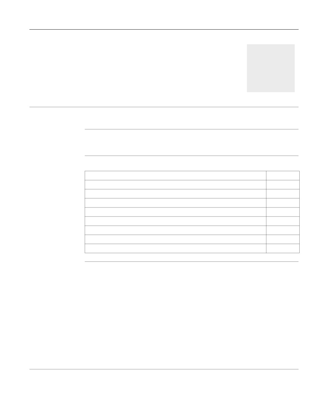
What’s in this
This chapter describes how to set up DFB function blocks.
chapter
What’s in this
This Chapter contains the following Maps:
Chapter?
Topic
Page
DFB types
260
Creating a DFB type
261
Programming a DFB type
262
DFB type instance
265
Running a DFB instance
267
Entering a DFB instance
268
How to protect a DFB
269
How to Import/Export a DFB type or an application containing DFB types
270
259
DFB function blocks
DFB types
At a Glance
DFB types (Derived Function Block) are function blocks which can be programmed
by the user in Structured Text or Ladder language.
These DFBs are used in an application to:
l simplify program design and entry,
l improve program readability,
l facilitate debugging (all variables manipulated by the DFB type are identified on
its interface),
l reduce the volume of code generated (the code corresponding to the DFB is only
loaded once, regardless of the number of calls to the DFB).
PL7 Pro software is needed to create a DFB type.
A DFB type can be used with PL7 Pro or PL7 Junior on a TSX/PCX/PMX 57 type
PLC.
A DFB type is called in an editor (LD, IL or ST) via an Instance of the DFB type that
is the image of the DFB type.
A DFB type instance can be used several times in a single application.
How to gain
Carry out the following actions:
access to the
Step
Action
DFB types’
properties
1
Select the DFB Type directory in the application browser.
2
From the contextual menu select the Properties command.
The properties of a DFB type can be accessed by two tabs:
l The "General" tab which gives the following information:
l version,
l date of last modification,
l programming language used,
l protection.
l The "Information" tab which gives the following information:
l number of elements (Inputs, Outputs, Inputs/Outputs, etc.),
l size of data,
l number of instances used in the application.
260
DFB function blocks
Creating a DFB type
Presentation
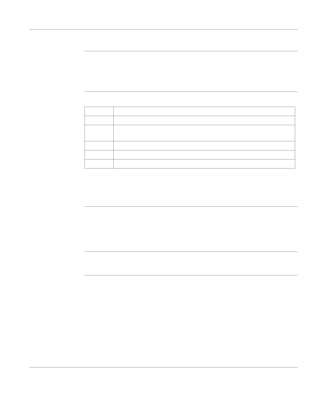
A DFB type can be made up in several steps:
l creating the DFB type (empty structure),
l DFB type parameters,
l DFB type programming (Code).
Creating the DFB
Carry out the following actions:
type
Step
Action
1
Open the application browser.
2
Right click with the mouse on the DFB type directory and select Create from
the context-sensitive menu.
3
Enter the name of the new DFB type.
4
Select the language Ladder or Structured tex.t.
5
Click on OK.
Note:
The choice of language Ladder or Structured text for the DFB code can be modi-
fied as long as the code is not entered.
Setting the
This is done using the DFB type editor. It consists of declaring:
parameters for
l the input, input/output and output interfaces,
the DFB type
l the public variables,
l the private variables,
l and documenting the description file.
DFB type
Programming a DFB is done using the DFB code editor which can be accessed
programming
from the DFB editor.
261
DFB function blocks
Programming a DFB type
Principles
The code defines the processing that the DFB type must carry out depending on the
declared interfaces.
All language instructions are permitted except for:
l calling up standard function blocks,
l calling up other DFB types,
l jumping to a label (JUMP),
l calling up a subroutine,
l instructions using input/output module variables (e.g. READ_STS, SMOVE etc.).
The code of the DFB type may only use:
l input/output objects (%I, %Q..),
l global application objects (%MW,%KW...) excluding %S and %SW bits and sys-
tem words.
There are functions specific to development of a DFB type such as:
l the timer functions, FTON, FTOF, FTP, FPULSOR, which can be used instead of
timer function blocks,
l the instructions, LW, HW, COCATW which are used to handle double words,
l the instructions, LENGTH_ARW, LENGTH_ARD, LENGTH_ARR, which are
used to calculate table lengths.
Programming
DFB instances can be used in various parts of the application, which use the lan-
rules
guages LD, IL or ST (apart from in event tasks).
l sections,
l subroutines.
The programming rules are as follows:
l All table type input parameters and input/output parameters must be entered.
l Unconnected input parameters keep the value of the previous call or the initial-
ization value if the block has never been called with this entered or connected in-
put.
l All the objects assigned to input, output and input/output parameters must be of
the same type as those entered at the time DFB Type creation,
l Only BOOL and EBOOL types can be mixed for input or output parameters.
262
DFB function blocks
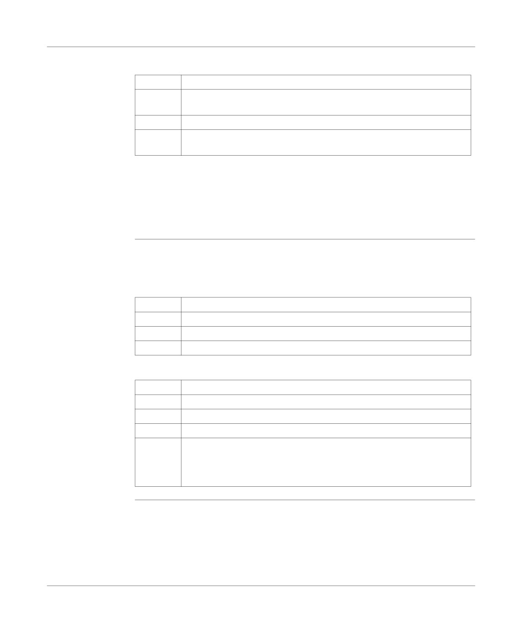
Entering and
Carry out the following steps:
modifying code
Step
Action
1
Click on Code in the DFB editor or select Utilities/Open then click on ENTER
to open the DFB code editor.
2
Enter the code.
3
Confirm the code.
Any confirmation made at DFB editor level is global.
Note:
DFB type code can only be entered or modified on an unprotected DFB type.
Code that has not been confirmed (in the process of being created or modified) is
indicated by a red dash in the left hand margin of the editor.
Search/Replace:
This function is used to search for and/or replace an object (interface or variable) in
to find or replace
the DFB code.
an object in the
code
Searching for an object:
Step
Action
1
Select Search/Replace... from the Edit menu
2
In the Search zone indicate the object to be searched for (e.g.: Input0).
3
Select Next to go to the different occurrences in the order in which they appear.
Search/Replace: to find/replace an object:
Step
Action
1
Select Search/Replace... from the edit menu.
2
In the Search zone indicate the object to be searched for (e.g.: Input0).
3
In the Replace zone indicate the object to be replaced (e.g.: Input1).
4
Select:
l Next to go to the first occurrence,
l Replace to replace only the current occurrence,
l Replace All to replace all occurrences.
263
DFB function blocks
Confirming a
Confirming a DFB type is a global operation which can be used to confirm the inter-
DFB type
faces, the variables, descriptive form and the code.
Carry out the following actions:
To confirm a DFB from…
you must…
DFB editor
click on the icon
or select Edit/Confirm then
press ENTER.
DFB code editor
click on the icon
or select Edit/Confirm DFB
type then press ENTER.
Note:
To confirm a DFB type, it must have at leastone Boolean input.
The DFB editor cannot be closed until the DFB type has been confirmed or can-
celed.
How to access a
This function is used to go to a line of code within the code of a given DFB type by
line of code
entering its numeric position.
Carry out the following steps to access a line of code:
Step
Action
1
When the code is displayed, select the Edit → Go to command.
2
Enter the line number then click OK.
Errors
If there is an interface, variable or code error, the DFB type cannot be confirmed,
and the system then positions itself at the first error.
You must:
1. Correct the error(s).
2. Reconfirm.
264
DFB function blocks
DFB type instance
Presentation
A DFB type instance is a named copy of a validated DFB type.
The same instance can be used several times in an application.
One DFB type can have several instances, in this case the Input/Output interfaces,
the public variables and the private variables are duplicated (one duplication per in-
stance). The DFB code is not duplicated.
The name given to an instance cannot be:
l a PL7 reserved word,
l a symbol,
l an EF (elementary function),
l the name of a DFB type.
Creating an
Carry out the following actions:
instance from an
Step
Action
application
browser
1
From the application browser, right click on the sub-directory DFB Variables/
Instances DFB.
2
Select the command Open.
3
Select the DFB type to be instanced using the mouse or the Tab and arrow
keys.
4
Enter the name of the new instance in the last line of the Name field (32 char-
acters maximum).
5
Enter a comment in the Comments field (80 characters maximum).
6
Click on ENTER.
Creating an
Carry out the following actions:
instance from the
Step
Action
function library
1
Select Library from the Tools menu then select the DFB tab.
2
Select the type of DFB to be instanced in a line of the Name field.
3
Click on the button Create.
4
Enter the name of the new instance (32 characters maximum).
5
Enter any comments.
6
Click on Create.
265
DFB function blocks
Modifying an
An instance is modified if its name and/or comments are modified.
instance
Modifying the name of an instance:
l leads to the automatic updating of its sub-objects,
l can only be carried out if it is not referenced.
Deleting an
Carry out the following actions:
instance
Step
Action
1
From the application browser, right click on the sub-directory DFB Variables/
Instances DFB.
2
Select the command Open.
1
If the instance is not referenced in the application:
Select the instance to be deleted in the Name column and delete it.
If the instance is referenced in the application:
1. Delete it in the corresponding language editor.
2. Select the instance to be deleted in the Name column and delete it.
266
DFB function blocks
Running a DFB instance
Rules
Running a DFB instance is done in the following order:
1. Loading the input and input/output parameters using the actual parameters.
Any input left free takes on the initialization value defined in the DFB type when be-
ing initialized or starting from cold, then the current value of the parameter.
The input parameters (except for table types) are sent by value, the input/output pa-
rameters are sent by address.
2. Running the text code, or ladder.
3. Writing the output parameters.
267
DFB function blocks
Entering a DFB instance
Presentation
Entering a DFB instance is done from:
l the ladder editor,
l the list editor,
l the structured text editor.
From the ladder
Carry out the following actions
editor
Step
Action
1
Click on the graphic element
in the graphics palette.
2
Select DFB.
3
Select the type of DFB required.
4
Select an instance required in Choice of instance or create a new instance
(name and any comments then click on Create.
5
Click on OK.
6
Click on the destination cell (Test zone) to set the type of DFB.
From the list or
Carry out the following actions:
structured text
Step
Action
editor.
1
Select the command Service/Enter function call or SHIFT+F8.
2
Select the DFB tab.
3
Select the required DFB block.
4
Select the required instance or create a new instance (any name + comments)
then click on Create.
5
Enter the DFB type parameters in the entry field parameters.
5
Confirm your selection by OK.
6
Confirm your selection by ENTER.
268
DFB function blocks
How to protect a DFB
Presentation
There are two protection levels for a DFB type:
l modification protection which limits access to the DFB type editor to read only,
l expertise protection which prevents access to the DFB type code and to its pri-
vate variables.
Protection is only applicable on a validated DFB type. It is managed by a password.
Protecting a DFB Carry out the following actions:
type
Step
Action
1
Open the DFB type editor.
2
Select Edit/Properties of the type.
3
Select the protection type.
4
Enter a password (8 characters maximum).
5
Confirm by entering the password again.
6
Click twice on OK.
Modifying
Carry out the following actions:
protection type
Step
Action
for a DFB type
1
Open the DFB type editor.
2
Select Edit/Properties of the type.
3
Select the new protection type.
4
Enter the password.
5
Click on OK.
Modifying the
Carry out the following actions:
password
Step
Action
1
Open the DFB type editor.
2
Select Edit/Properties of the type.
3
Select Change.
4
Enter the current password.
5
Enter the new password (8 characters maximum).
6
Confirm by entering the password again.
7
Click on OK.
269
DFB function blocks
How to Import/Export a DFB type or an application containing DFB types
Exporting/
Refer to the "Import/Export" Chapter of the Part "Debugging, Adjustment, Doc-
Importing a DFB
umentation and Appendices".
type
See Exporting a standard format DFB type, p. 376.
See Export of a binary format DFB type, p. 377.
See Importing a DFB type in binary format, p. 378.
See Importing a DFB type in binary format, p. 378.
Exporting/Im-
Refer to the "Import/Export" Chapter of the Part "Debugging, Adjustment, Doc-
porting an
umentation and Appendices".
application
containing DFB
See Exporting an application with DFB, p. 380.
types.
See Importing an application with DFBs, p. 382.
270
Debugging, adjustment,
documentation and appendices
III
Introduction
Subject of this
This section gives information about the application context and describes how to:
section
l Debug an application.
l Diagnose an application.
l Export/Import application modules.
What’s in this
This Part contains the following Chapters:
part?
Chapter
Chaptername
Page
13
Debugging
273
14
Adjustment of variables
309
15
Diagnostic functions
321
16
Documentation
333
17
Import/Export
341
18
Configuring the Uni-telway link
387
19
Configuring the FIPWAY link
399
20
OS Loader
409
21
Windows
417
271
Debugging, adjustment, documentation and appendices
272
Debugging
13
Introduction
Subject of this
This chapter describes the PL7 debugging functions.
chapter
What’s in this
This Chapter contains the following Maps:
Chapter?
Topic
Page
Introduction to the PLC debugging screen
275
CPU screen designation zone
276
Information zone
277
Task Zones
278
Operating mode zone
280
Event zone
281
Last stop zone
282
Realtime clock zone
283
Modification of the program in Run mode
284
Animating program elements
285
Grafcet debugging
288
Executing the programme
291
Task properties
292
Executing the MAST task
293
Executing the FAST task
295
Execution of a program with breakpoint
297
Executing a program in step by step mode.
300
Forcing TOR input
302
Forcing analog inputs, TSX Micro
303
Forcing analog inputs, TSX Premium
304
273
Debugging
Topic
Page
Adjustment of the application specific functions
305
Debugging a functional module
306
Debugging DFBs
308
274
Debugging
Introduction to the PLC debugging screen
How to access
Carry out the following steps:
the PLC
Step
Action
debugging
1
Click on the Debug menu on the PL7 task bar.
screen
2
Click on the Access PLC debugging screen sub-menu.
PLC Debugging
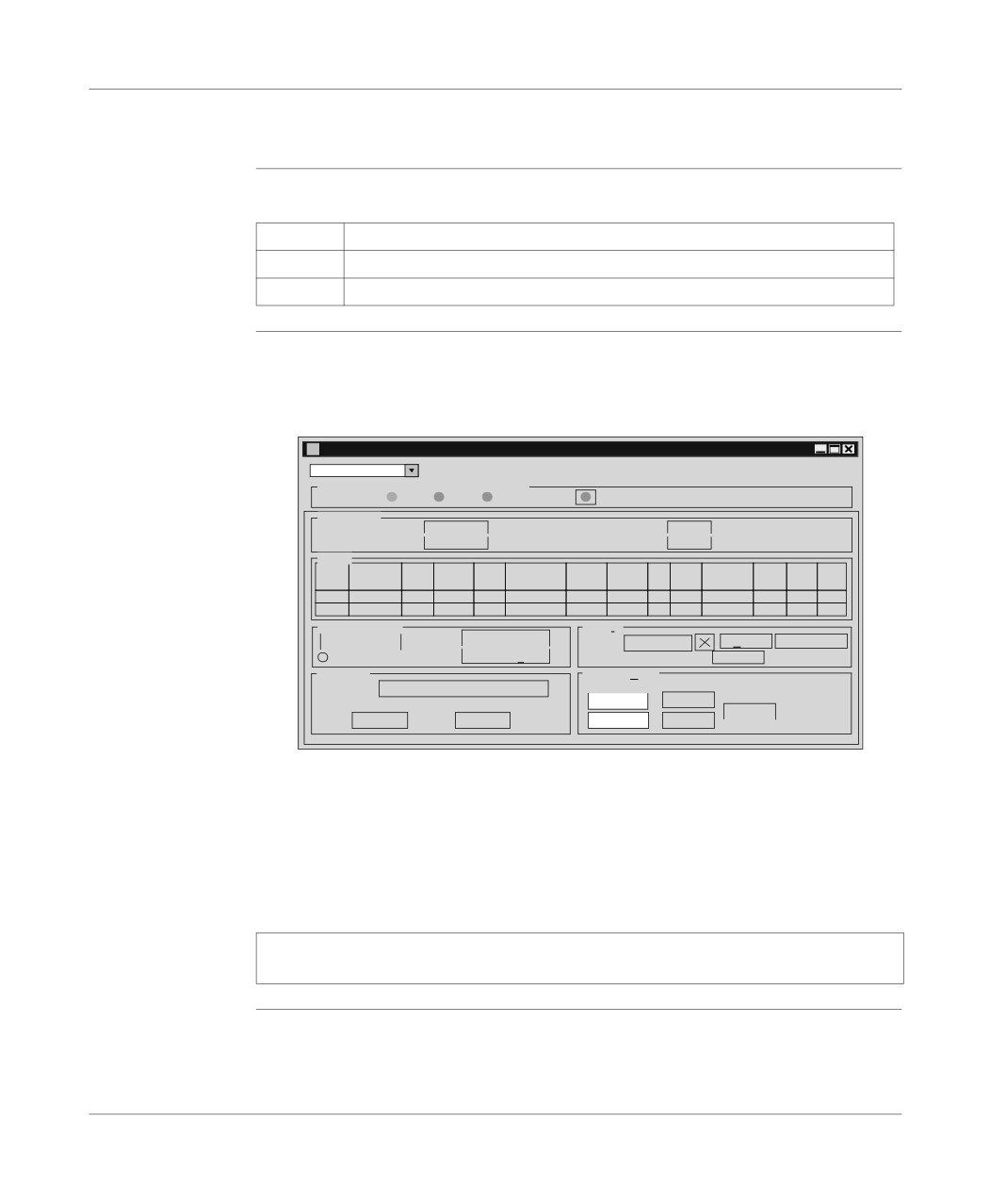
ThePLC debugging screen offers different functions and information, which are di-
screen
vided up into zones:
PLC debugging screen :
TSX 57352 [RACK 0 POSITION 0]
Debugging
Designation: PROCESSOR TSX P 57352
RUN IO
ERR
DIAG...
Information
Processor present:
TSX 57352
Processor version:
3.7(88)
Network address:
SYS
Number of forced bits:
0
Task
Period
Min.
Current
Max.
Cycle time
Watch
Opera-
Stat
Cmd
Enable
Error
Init
Reset
Set
Duratio
DurationDurati
Fipio
Dog
ting
us
task
duratio
Def
MAST
CYCLIC
2
6
6
0
250
STOP a Run Deactivate Def Init Reset
FAST
0
0
0
0
0
0
Not
Operating mode
Events
Output fallback
Warm Restart
Status:
Active STOP
Error
Bit error reset
Outputs in fallback mode
Cold Start
Number of events:
0
Last stop
Realtimeclock
Cause
Change to stop
Wednesday
Wednesday
23/02/
OK
Update
Date:
23/02/
Time:
10:16:33
10:27:08
Cancel
l
Designation (See CPU screen designation zone, p. 276) zone,
l
Information (See Information zone, p. 277) zone,
l
Task (See Task Zones, p. 278) zone,
l
Operating mode (See Operating mode zone, p. 280) zone,
l
Event (See Event zone, p. 281) zone,
l
Last stop (See Last stop zone, p. 282) zone,
l
Real time clock (See Realtime clock zone, p. 283) zone.
Note: To access the debugging functions you need to be in online mode (PLC →
Connect).
275
Debugging
CPU screen designation zone
At a Glance
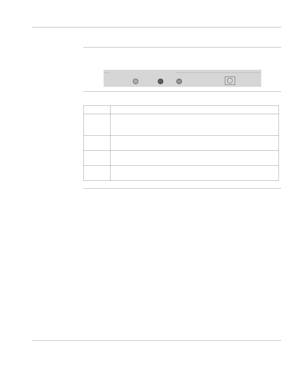
This zone allows you to find out the execution status of an application in the PLC.
Designation Zone:
Designation: PROCESSOR TSX P 57352
RUN
IO
ERR
DIAG...
Description
Elements and their functions:
Element
Function
The RUN
This indicates the state of the PLC:
indicator
l it is constant when the PLC is in RUN,
l it blinks when the PLC is in STOP.
The I/O in-
Red light indicating the errors on another module in the station or a configura-
dicator
tion error.
The ERR
Red light indicating the errors relating to the processor and its on-board devic-
indicator
es (PCMCIA memory card and PCMCIA communication card).
The DIAG
It gives access to diagnostics information.
button
276
Debugging
Information zone
At a Glance
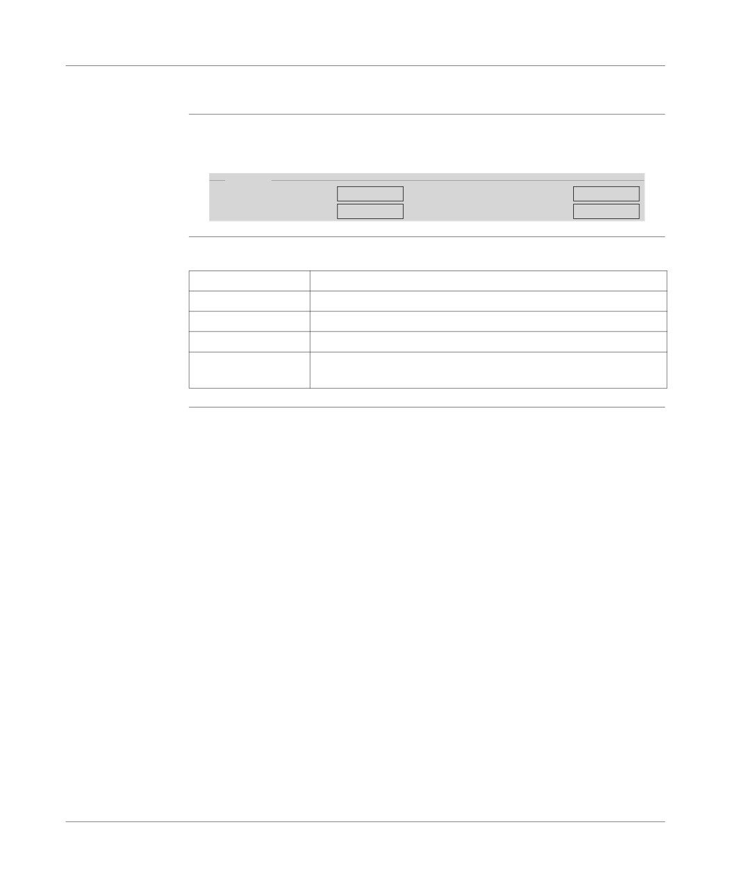
This zone provides miscellaneous information:
Information zone:
Information
Processor present:
TSX 57352
Processor Version:
3.7(88)
Network address:
SYS
Number of forced bits:
0
Description
Fields and their function:
Field
Function
Processor present
Provides information about the type of processor in the PLC.
Network Address
Provides information about the PLC network address.
Processor version
Gives the version of the processor which is in the PLC.
Number of forced
Indicates the number of forced bits.
bits
277
Debugging
Task Zones
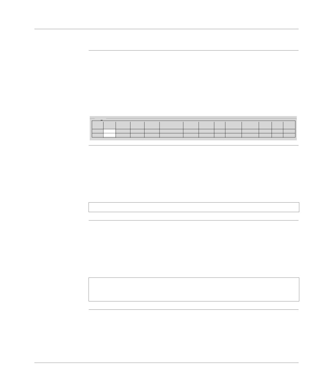
At a Glance
This zone gives access to the various FAST task and MAST task execution com-
mands:
l RUN/STOP commands,
l Activate/Deactivate Task commands,
l setting periods,
l Period Initialization command,
l Error Management commands.
Task Zone:
Tasks
Period Minimum
CurrentMaximum
Cycle time
Watch
Operating
Enable
Init
Reset
Status
Cmd
Fault
Set
Duration DurationDuration
Fipio network
Dog
Mode
task
duration
Fault
MAST
40
4
10
55
4
250
RUN
a
Stop
Deactivate
Fault
Init
Reset
FAST
5
1
1
3
0
100
RUN
a
Stop
Deactivate
Fault
Init
Reset
MAST or FAST
The RUN/STOP buttons associated with the MAST and FAST tasks are used to
task RUN/STOP
switch to RUN or STOP mode.
command
In RUN mode the inputs are read, the program is executed and the outputs are re-
freshed.
In STOP mode the inputs are read, the program is not executed and the outputs are
not refreshed.
Note: These functions are also accessible via the Debug menu.
MAST or FAST
The Activate/Deactivate buttons associated with the MAST and FAST tasks are
task Activate/
used to activate or deactivate a task.
Deactivate
When a task is activated, the code is scanned and executed. The inputs/outputs are
command
refreshed.
When a task is deactivated, the code is neither scanned nor executed. The inputs/
outputs are still refreshed.
Note: The Status field informs you of the status of a task:
l a: for active (the system bits %S30 and %S31 are set at 1),
l i: for inactive (the system bits %S30 and %S31 are set at 0).
278
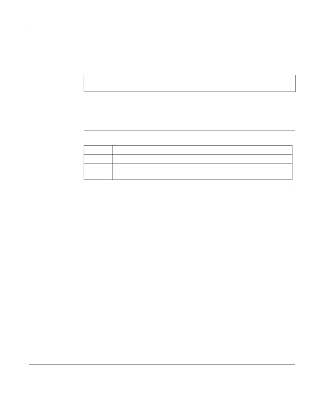
Debugging
Setting periods
In periodic operation, the "Period set" column is used to set the task period. This set-
ting is lost on cold start. The value entered in the configuration is then taken into ac-
count. It is possible to save the period set using theUtility → Save task periods
command.
Note: The Utility → Restore task periods command replaces the period set with
the period defined in the configuration.
Error initializa-
The minimum, current and maximum durations are provided by the PLC.
tion command
The Init button in the Init column restores these values in order to carry out new
measurements (except the current duration).
Error
Buttons and functions:
management
Button
Function
commands
Fault bit
Enables any errors in the corresponding task to be viewed.
Reset
Is used to reset the system bits associated with the task errors to zero, in order
to be sure that the error(s) is/are still valid.
279
Debugging
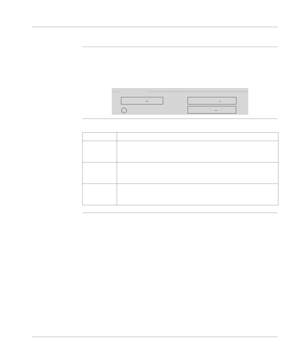
Operating mode zone
At a Glance
This zone gives access to various modeling buttons:
l Warm restart,
l Cold start,
l Output fallback.
Operating Mode Zone:
Operating mode
Output fallback
Warm restart
Outputs in fallback mode
Cold start
Description
Buttons and functions:
Button
Function
Warm Restart
Click on this button to simulate a warm PLC restart.
This sets the %S1 bit to 1, which for example is used to command a partial
initialization program.
Cold start
Click on this button to simulate a cold PLC start.
This initializes the data, the system, and sets the %S0 bit to 1 which (in this
case) is used for example to command a specific initialization program.
Output fall-
Is used to switch the outputs into fallback mode.
back
When the outputs are in fallback, the Output fallback button becomes Main-
tain outputs. It is therefore used to exit the fallback mode.
280
Debugging
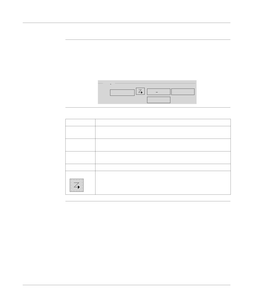
Event zone
At a Glance
Event processing can be globally enabled or inhibited by the application program by
means of the %S8 system bit or a terminal command (program debugging function).
If one or several events occur whilst they are inhibited, the associated processing is
lost.
The Event zone gives access to different functions.
Event Zone:
Events
Status:
RUN inactive
Fault
Reset Fault Bit
Number of events:
0
Description
Elements and functions:
Element
Function
Number of
Indicates the number of events executed.
events
Default button
Is used to view the default bits and to access the events diagnostics pro-
gram.
Reset fault bit
Is used to reset the fault bits associated with the execution of events to zero.
button
Status field
Informs about the status of an event (active/inactive, RUN/STOP).
Icon
Is used to activate/deactivate events.
281
Debugging
Last stop zone
At a Glance
This zone gives the diagnostics on the last stop of the PLC.
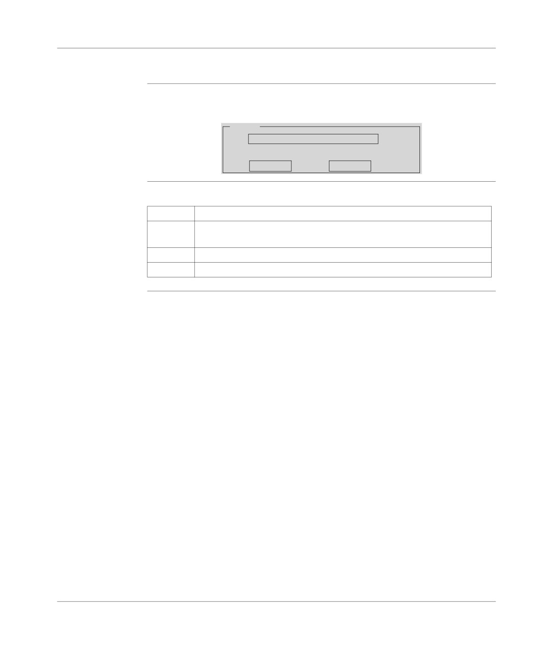
Last stop zone:
Last stop
Cause
Change to Stop
Tuesday,
Date:
29/02/2000
Time:
09:31:59
Description
Fields and functions:
Field
Function
Cause
Gives the causes for the last stop of the PLC.
field
Date field
Gives the date of the last stop of the PLC.
Time field
Gives the time of the last stop of the PLC.
282
Debugging
Realtime clock zone
At a Glance
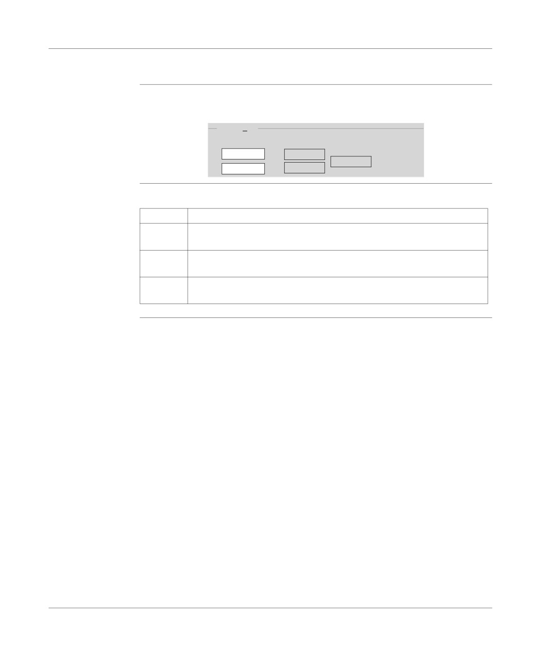
This zone gives access to the realtime clock settings.
Realtime clock zone:
Realtimeclock
Tuesday,
29/02/2000
OK
Update
11:09:49
Cancel
Description
Buttons and functions:
Button
Function
OK button
Is used to confirm once the date and the time have been set using the double
arrows.
Update
Updates the realtime clock according to the date and time of the terminal.
button
Cancel
Cancels all modifications if the PLC update has not been confirmed.
button
283
Debugging
Modification of the program in Run mode
Introduction
The program editor authorizes the modification of the application in RUN mode, ex-
cept for the Grafcet structure part.
Principals
Modification of program elements LD, IL, ST PLC in RUN, is possible at the level of
a LD rung, of an IL statement or of an ST instruction, except if the contents are con-
tained in an event processing (EVTi).
The situation with Grafcet: only the processing linked to steps and transitions can
be modified, Grafcet can not be modified.
CAUTION
For security reasons, you are advised to start the PLC programming at
the stopSTOP. Modification in RUNmode must be used for program
modifications which do not require the application to be stopped and are
under the responsibility of the user.
Failure to observe this precaution can result in injury or equip-
ment damage.
The operate
The operate modes are the same as for modification in PLC local mode or connect-
modes
ed mode in STOP mode. However some modifications are applied:
l no jump on an undefined label,
l not to be in step by step mode or have set a breakpoint,
l the PLC must not be at default,
l the multi-rung functions are not authorized,
l it is impossible to add a function block which is not already represented in the ap-
plcation.
284