PL7 JUNIOR/PRO Operate modes manual (Operate modes manual eng V4.0) - page 6
Programming in Grafcet language
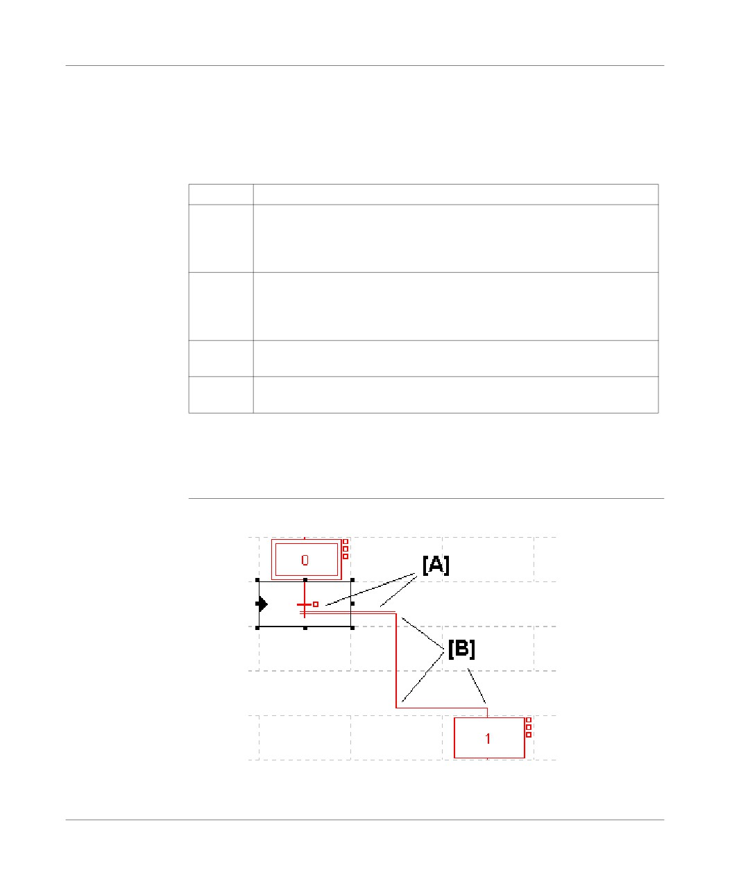
Entering a
A macro-step must be:
Macro-Step
l defined in order to be inserted in a Grafcet module (chart or macro-step),
l created (using the application browser) in order to be entered in a Grafcet module
(chart + macro-step),
l completed (number of the corresponding macro-step) in order to be validated.
Carry out the following actions:
Step
Action
1
Using the mouse:
Click on the graphical object situated in the graphical palette.
Using the keyboard:
Position the cursor on the grid at the required place (using the arrow keys).
2
Using the mouse:
Click on the grid at the required place.
Using the keyboard:
Press the function key corresponding to the Macro-step object (Shift +F2)
3
Using the mouse or the keyboard:
Enter a macro-step number, then confirm with ENTER.
4
Using the keyboard:
Confirm the chart using the ENTER key, or using the command Edit/Confirm.
Note:
When a chart is confirmed, the display changes:
l the graphical objects change from red to black,
l the page border becomes gray.
Carrying out an
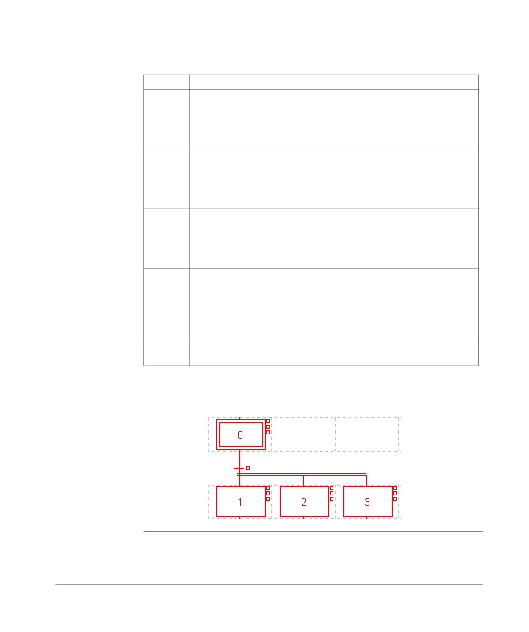
An AND divergence starts with a transition and goes to a step.
AND divergence
205
Programming in Grafcet language
Carry out the following actions:
Step
Action
1
Using the mouse:
Click on the graphical object situated in the graphical palette (F11).
Using the keyboard:
Put the cursor on the start transition or on the pre-existing divergence segment
[A] (in the case of multiple divergence) using the arrows.
2
Using the mouse:
Click on the start transition or on the pre-existing divergence segment [A] (in
the case of a multiple divergence).
Using the keyboard:
Press (F11).
3
Using the mouse:
Draw the link by clicking on the break points of the line [B] (change of direction)
in the transition lines.
Using the keyboard:
Draw the link using the arrow keys.
4
Using the mouse:
Double click on the last break point or click again on the graphical object situ-
ated in the graphical palette (F11).
Using the keyboard:
Press F11 again on the last break point. If the destination cell is empty, a step
is automatically created.
5
Using the mouse or the keyboard:
Modify the step number if applicable, then confirm using ENTER.
Note:
An AND divergence is always represented from left to right, the segment represent-
ed by a double line cannot be cut by another link.
206
Programming in Grafcet language
Carrying out an
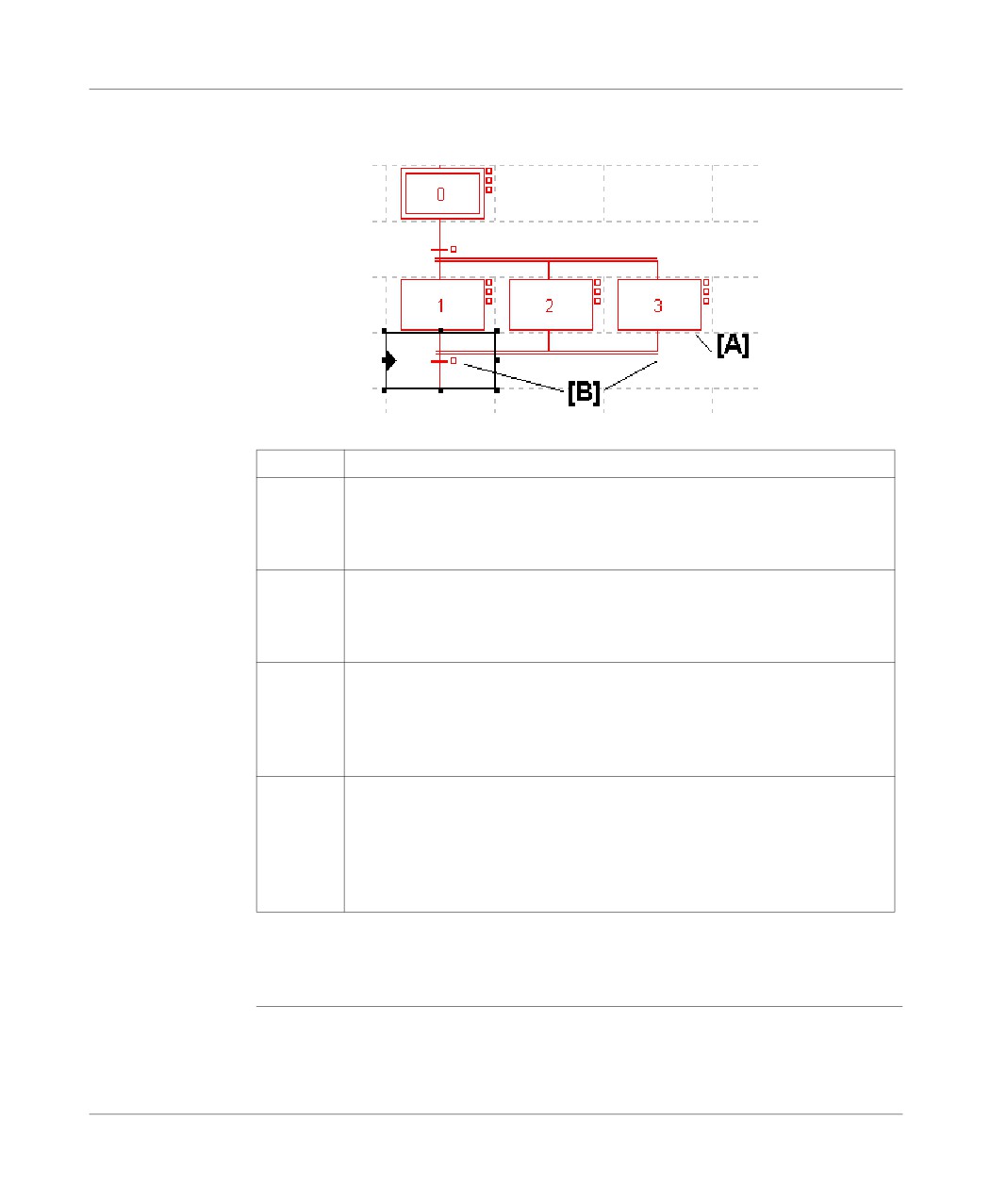
An AND convergence starts with a step and goes to a transition.
AND
convergence
Carry out the following actions:
Step
Action
1
Using the mouse:
Click on the graphical object situated in the graphical palette (F10).
Using the keyboard:
Put the cursor on the start step using the arrow keys.
2
Using the mouse:
Click on the start step [A].
Using the keyboard:
Press (F10).
3
Using the mouse:
Draw the link by clicking on the break points of the line [B] (change of direction)
in the transition lines.
Using the keyboard:
Draw the link using the arrow keys.
4
Using the mouse:
If the destination cell is empty, double click on the last break point or click again
on the graphical object situated in the graphical palette to create the transition.
Using the keyboard:
If the destination cell is empty, press (F10) again on the last break point to cre-
ate the transition.
Notes:
The segment represented by a double line cannot be cut by another link.
An AND convergence can only be entered from right to left.
207
Programming in Grafcet language
Carrying out a
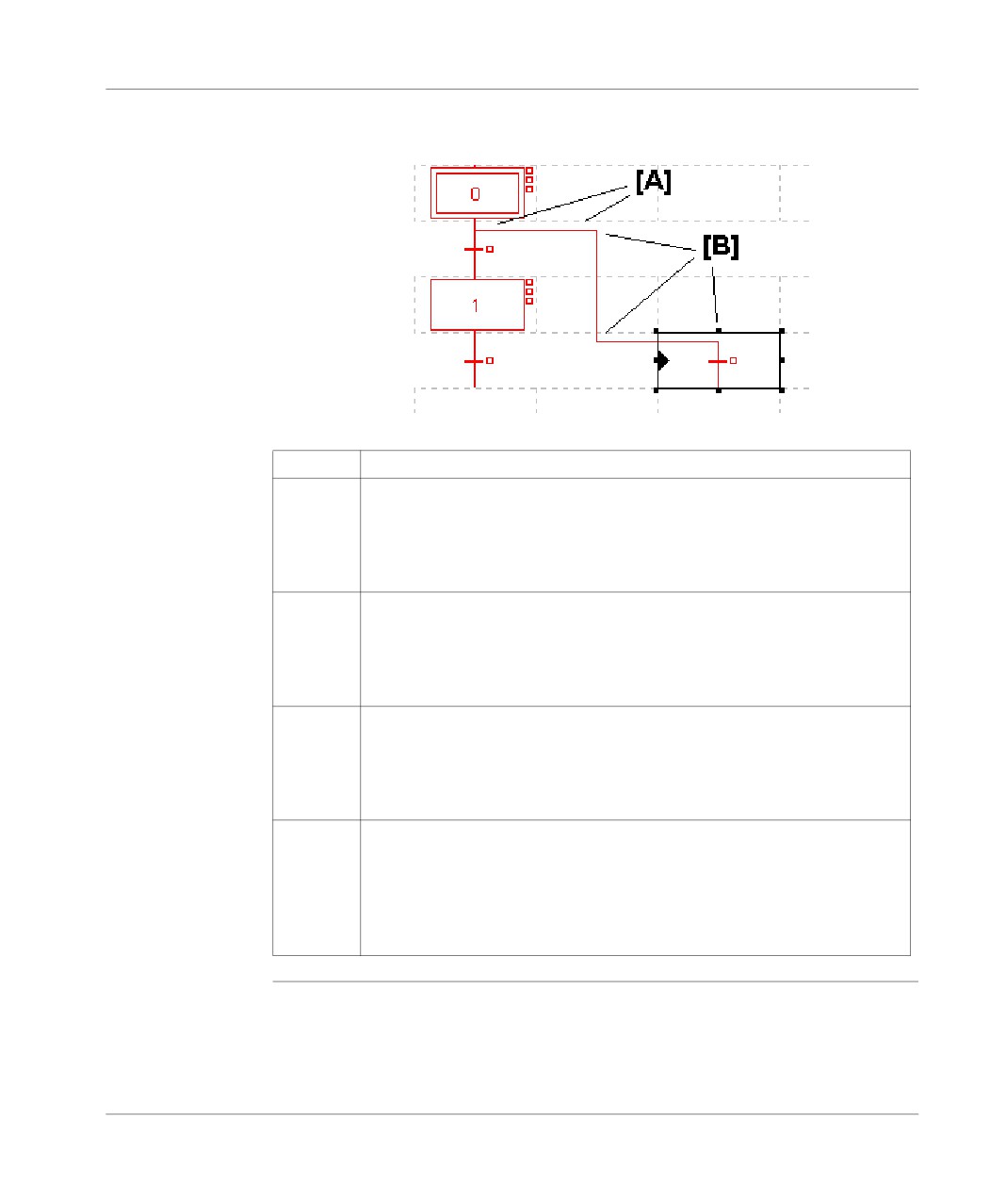
A step -> transition link starts with a step and goes to a transition.
Step ->
Transition link
Carry out the following actions:
Step
Action
1
Using the mouse:
Click on the graphical object situated in the graphical palette (F8).
Using the keyboard:
Put the cursor on the start step or on the pre-existing step -> transition link seg-
ment [A] (in the case of multiple link) using the arrows.
2
Using the mouse:
Click on the start step or on the pre-existing step -> transition link segment [A]
(in the case of a multiple link).
Using the keyboard:
Press (F8).
3
Using the mouse:
Draw the link by clicking on the break points of the line [B] (change of direction)
in the transition lines.
Using the keyboard:
Draw the line using the arrow keys.
4
Using the mouse:
If the cell is empty, double click on the break point or click again on the graph-
ical object situated in the graphical palette to create the transition.
Using the keyboard:
If the destination cell is empty, press (F8) again on the last break point to create
the transition.
208
Programming in Grafcet language
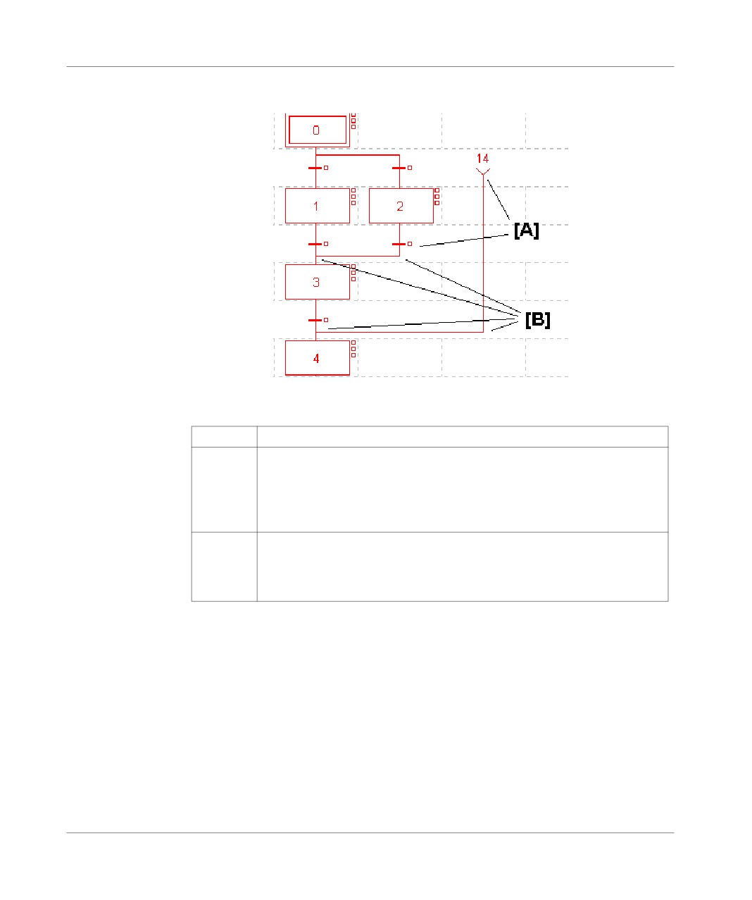
Carrying out a
A transition -> step link starts with a transition and goes to a step.
Transition ->
Step link.
Carry out the following actions:
Step
Action
1
Using the mouse:
Click on the graphical object situated in the graphical palette (F9).
Using the keyboard:
Put the cursor on the start transition or the source connector using the arrow
keys.
2
Using the mouse:
Click on the start transition or the source connector [A]
Using the keyboard:
Press (F9).
209
Programming in Grafcet language
Step
Action
3
Using the mouse:
Draw the link by clicking on the break points of the line [B] (change of direction)
in the transition lines.
Using the keyboard:
Draw the link using the arrow keys as far as the step or the destination connec-
tor.
4
Using the mouse:
If the destination cell is empty, double click on the last break point or click again
on the graphical object situated in the graphical palette to create the step.
Using the keyboard:
If the destination cell is empty, press (F9) again on the last break point to create
the step.
5
Using the mouse or the keyboard:
Modify the step number if applicable, then confirm using ENTER.
210
Programming in Grafcet language
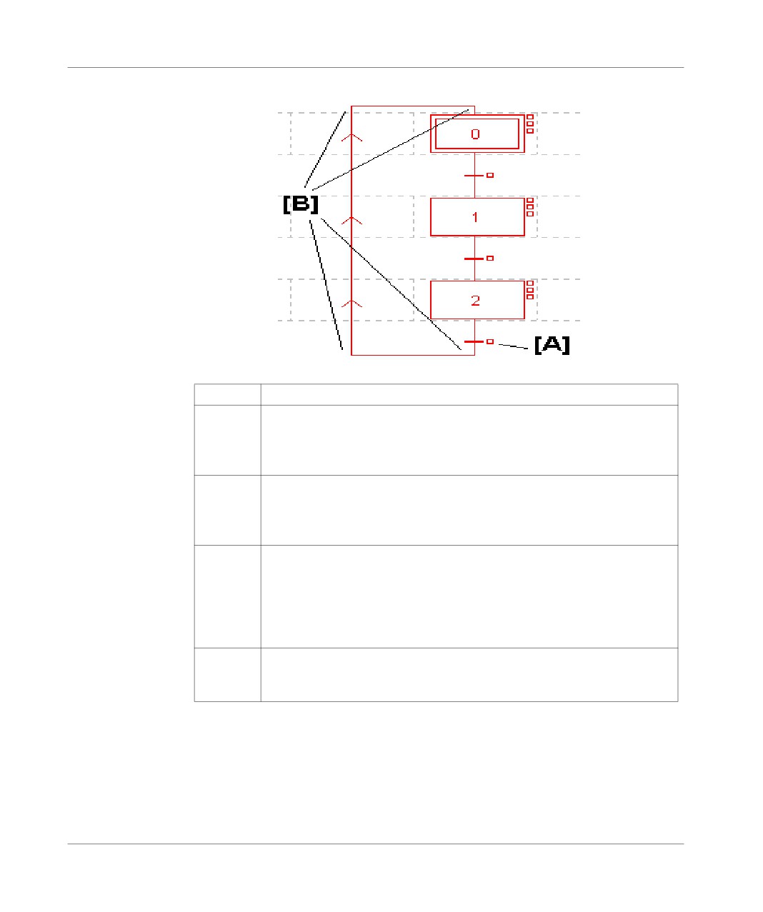
Carrying out a
Two types of loop iteration are available to complete a chart:
loop iteration
Using directed links:
Step
Action
1
Using the mouse:
Click on the graphical object situated in the graphical palette (F9).
Using the keyboard:
Put the cursor on the start transition [A] using the arrow keys.
2
Using the mouse:
Click on the end of chart transition [A].
Using the keyboard:
Press (F9).
3
Using the mouse:
Draw the link by clicking on the break points of the line [B] (change of direction)
in the transition lines.
Using the keyboard:
Draw the link using the arrow keys as far as the step or the destination connec-
tor.
4
Using the mouse:
Double click on the step to be linked or click again on the graphical object sit-
uated in the graphical palette to validate the object.
211
Programming in Grafcet language
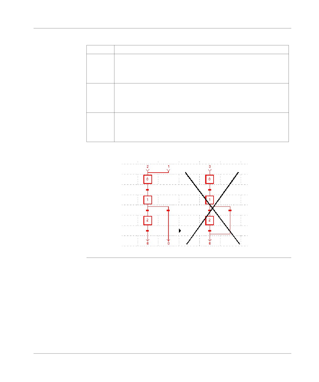
Using connectors:
Step
Action
1
Using the mouse:
Click on the graphical object situated in the graphical palette (F5 or F7)
Using the keyboard:
Place the cursor in the required place.
2
Using the mouse:
Click on the grid at the required place.
Using the keyboard:
Select the required graphical object by pressing (F5 or F7).
3
Using the mouse:
Complete the source or destination step number, then confirm using ENTER.
Using the keyboard:
Complete the source or destination step number, then confirm using ENTER
Example of loop iteration using connectors:
212
Programming in Grafcet language
Programming
Carry out the following actions:
actions
Step
Action
1
Using the mouse:
Select the step with a right click.
Using the keyboard:
Put the cursor on the step using the arrow keys, then confirm the selection by
using the command (Shift+F10).
2
Using the mouse:
Select the type of action associated with the step (activation action, continuous
action or deactivation action).
Using the keyboard:
Use the arrow keys to select the type of action associated to the step that is to
be modified, then confirm with ENTER.
3
Using the mouse:
Select the type of language:
l ladder language LD,
l instruction list language IL,
l structured text language ST,
and confirm withOK
Using the keyboard:
Select the type of language using the arrow keys:
l ladder language LD,
l instruction list language IL,
l structured text language ST
and confirm with OK.
4
Complete the programming.
213
Programming in Grafcet language
Programming
Carry out the following operations:
the transition
step
Action
conditions
1
Using the mouse:
Select the transition with a right click.
Using the keyboard:
Put the cursor on the transition using the arrow keys, then confirm the selection
by using the Service/Open command.
2
Using the mouse:
Select Open
Using the keyboard:
Select the type of language using the arrow keys:
l ladder language LD,
l instruction list language IL,
l structured text language ST,
and confirm with ENTER.
3
Using the mouse:
Select the type of language:
l ladder language LD,
l instruction list language IL,
l structured text language ST
and confirm with OK
Using the keyboard:
Complete the programming.
4
Using the mouse:
Complete the programming.
Limitations:
l in ladder language (LD) only the follow elements can be used:
l test graphical elements: contacts (Bi, I/O, Ti, D…), comparison blocks,
l action graphical elements: only "transition condition" coils (other coils not be-
ing relevant in this case).
l in instruction list language (IL) the following objects are prohibited:
l no labels (%L),
l no action instructions (bit objects, words or function blocks),
l no jumps, sub-routine calls.
l in structured text language (ST) the following objects are prohibited:
l no labels (%L),
l no action statements, conditional statements or iterative statements,
l no actions on bit objects,
l no jumps, sub-routine calls,
l no transfers, no action instructions on blocks.
214
Programming in Grafcet language
Entering
Carry out the following actions:
comments
Step
Action
1
Using the mouse:
Click on the graphical object situated in the graphical palette
Using the keyboard:
Position the cursor on the grid at the required place (using the arrow keys).
2
Using the mouse:
Click on the grid at the required place.
Using the keyboard:
Press the function key (F12).
3
Enter the comment (access the second line using (CTRL+ENTER).
4
Confirm with ENTER.
Notes:
Comments are not mandatory.
They are stored on the PLC, as a consequence they take up memory.
215
Programming in Grafcet language
Modifying a Grafcet program
Introduction
A Grafcet module (Graphic object, Step number, Macro-step (TSX 57 only), Com-
ment), is modified in the same way as it is created.
Actions and transition conditions are modified in the same way as they are created.
Rules for
A modification is authorized on any Grafcet page if:
modifying a chart
l no other modification is in progress in the editor,
l no language editor is open on a transition condition or action module.
Modifications can only be entered on the page in the process of being modified
(chart displayed in red).
Modifications can be only made in Offline or Online mode, with the PLC in STOP
mode.
Modifications cannot be made:
l in step by step program,
l when a breakpoint is set in the program.
Modifying a
Carry out the following actions:
graphic object,
Step
Action
comment, step
1
Put the cursor on the required Grafcet page (See Structure of a Grafcet page,
number or
p. 197).
connector
2
Using the mouse:
Left double click on the element to be modified (the chart goes into modification
mode, and is displayed in red).
Using the keyboard:
Put the cursor on the element to be modified.
3
Using the mouse:
Make the modification.
Using the keyboard:
Press the space bar (the chart goes into modification mode, and is displayed
in red).
4
Using the mouse:
Confirm with ENTER.
Using the keyboard:
Make the modification.
5
Using the keyboard:
Click on ENTER.
216
Programming in Grafcet language
Modifying a
The procedure for modifying a macro-step or a macro-step number is the same as
Macro-Step
the procedure for modifying a step or a step number.
A macro-step can be accessed by selecting the macro-step in the application brows-
er or by selecting the macro-step object in the Grafcet page.
Modifying an
Carry out the following actions:
action:
Step
Action
1
Put the cursor on the required Grafcet page (See Structure of a Grafcet page,
p. 197)
2
Using the mouse:
Select the action to be modified by right clicking on the associated step.
Using the keyboard:
Using the arrow keys, put the cursor on the associated step then confirm the
selection by using the Service/Open command.
3
Using the mouse:
Select the type of action associated to the step that is to be modified.
Using the keyboard:
Use the arrow keys to select the type of action associated to the step that is to
be modified, then confirm with ENTER.
4
Make the modification.
Modifying a
Carry out the following actions:
transition
Step
Action
condition
1
Put the cursor on the required Grafcet page (See Structure of a Grafcet page,
p. 197).
2
Using the mouse:
Select the transition condition to be modified by right clicking on the associated
step.
Using the keyboard:
Using the arrow keys, put the cursor on the associated step then confirm the
selection by using the Service/Open command.
3
Using the mouse:
Select Open.
Using the keyboard:
Make the modification.
4
Using the mouse:
Make the modification.
217
Programming in Grafcet language
Cut/Copy/Paste/
These actions can be performed on graphic objects and any programs associated
Move one or
with them. They can be made in offline and online mode, with the PLC in Stop mode.
more
Carry out the following actions:
consecutive
To…..
you must…
objects.
copy one object or several con-
l
1. Select the object or objects to be copied.
secutive objects
l
2. Select Copy from the Edit menu or press
CTRL+C (keyboard shortcut) and the Grafcet ob-
jects are placed on the Windows clipboard.
paste one object or several con-
l
1. Select the cell where the object or objects on the
secutive objects from the clip-
clipboard are going to be pasted.
board
l
2. Select Paste from the Edit menu or press
CTRL+V (keyboard shortcut) and the ghosted selec-
tion appears.
l
3. Click on the ghost or press ENTER to make the
pasted objects appear.
cut (delete) one object or several
l
1. Select the object or objects to be cut.
consecutive objects and place
l
2. Select Cut from the Edit menu or press CTRL+X
them on the clipboard
(keyboard shortcut) and the Grafcet objects are
placed on the Windows clipboard.
move one object or several con-
l
1. Select the object or objects to be moved.
secutive objects
l
2. According to your choice:
l Left click (keeping the button held down) on the
selected cell or cells then move the cursor to-
wards the destination cell or cells.
l Select Move from the Edit menu or CTRL+L
(keyboard shortcut) then using the arrow keys
move the cursor towards the destination cell(s).
218
Programming in Grafcet language
Replacing a variable in the application
At a Glance
Finding and replacing an application variable in the form of an address or a symbol
(excluding variables used in runtime screens). Replacement in the application may
be total or partial, automatic or manual.
Replacement concerns the variable indicated and its dependent objects (word ex-
tract bits etc.).
Exception: for Grafcet step bits the associated activity times (e.g. %Xi.T) are not re-
placed.
Replacement is carried out at the following levels:
l Application (in all tasks).
l Tasks (MAST, FAST, Evti).
l Complete section.
l Partial section (from address i to address j).
l Replacement is also carried out at functional module level (complete functional
module, sub-modules included).
Procedure
Carry out the following actions:
Step
Action
1
Select the commandTools/Replace variables or position the cursor over the
Station directory and select Replace variables from the contextual menu.
2
Indicate the variable to be replaced (as an address or a symbol) in the Find
zone and confirm with ENTER or TAB.
3
Indicate the replacement variable (as an address or a symbol) in the Replace
field and confirm with ENTER.
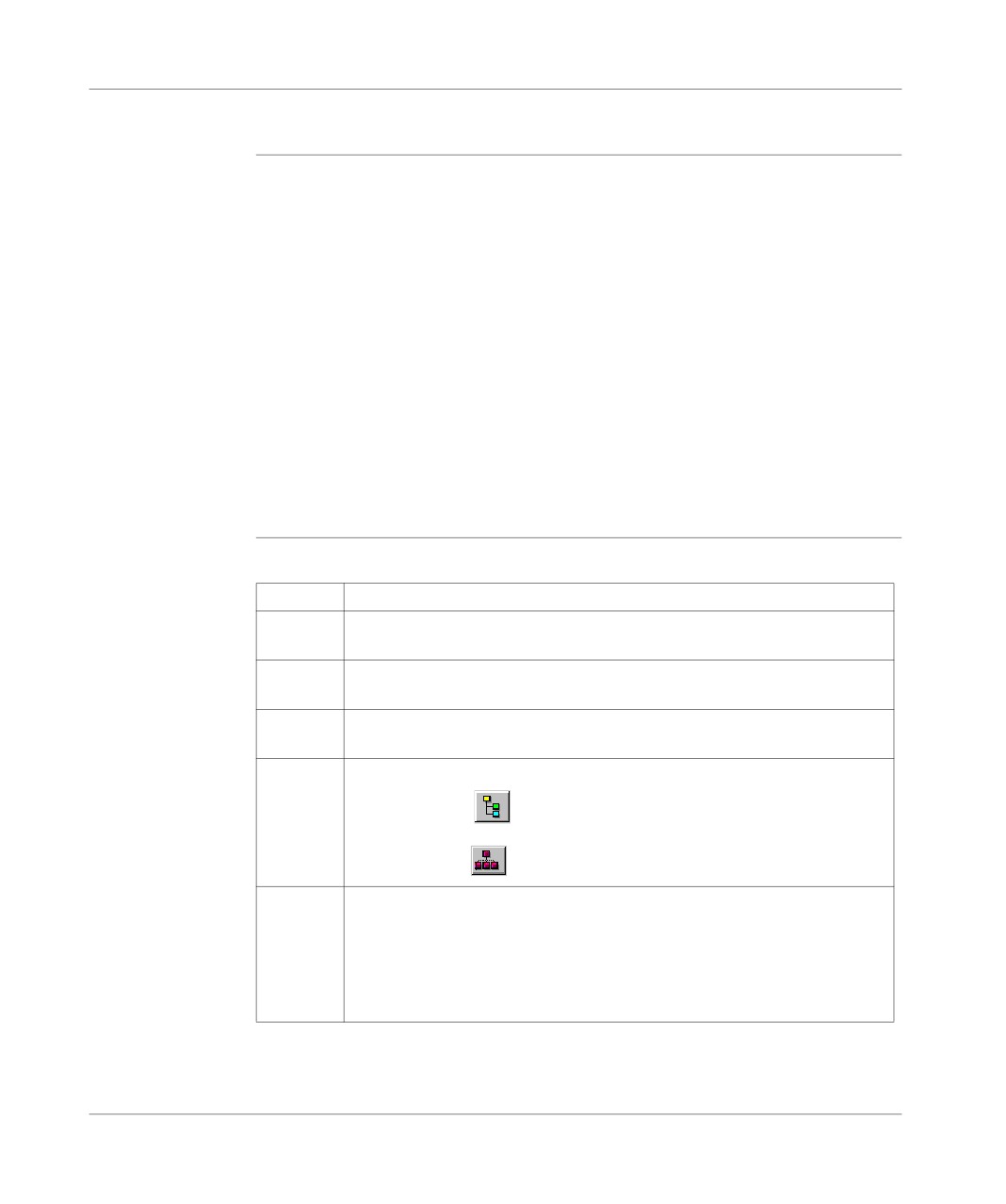
4
Select the view:
l Structure view
l Function view
5
Select one or more modules:
l if replacing throughout application, go to point 8,
l if replacing in some of the modules, deselect all, select the modules, and go
to point 6,
l if replacing in one of the modules, deselect all and select the module, and
go to point 6.
219
Programming in Grafcet language
Step
Action
6
Select the label (if LD, ST, IL) or the page (if G7) at the beginning of the re-
placement by positioning the pointer on the listFrom.
If more precision is required, use the up and down arrow keys.
7
Select the label (if LD, ST, IL) or the page (if G7) at the end of the replacement
by positioning the pointer on the listTo.
If more precision is required, use the up and down arrow keys.
8
Select the type of replacement:
l if Next, the replacement is carried out occurrence by occurrence,
l if Replace All, the replacement is carried out on all occurrences.
Notes:
l The status bar indicates the number of replacements carried out, and a re-
port on the replacements not carried out.
l The ESC key is used to abort the function Replace, but the replacements
already carried out are retained.
220

Programming in Grafcet language
Cross Referencing a variable in an application
Introduction
This function allows you to locate in the application:
l variables in the form of labels or symbols (except those used in operating
screens),
l DFB types (only on TSX Premium with Pl7 Junior and Pro),
l DFB instances (only on TSX Premium with Pl7 Junior and Pro),
l and to open modules/tasks/DFB types.
Principals of
The user realizes that the variable X is not the right value. To identify the cause he
using debugging
must therefore:
l find the places where this variable is used,
l obtain a list of statements, rungs and expressions,
l to display and verify the activation conditions of the variable.
Note:
In order to record the path of this search, the list elements thus visited are marked
with an asterisk (*).
Operational
A variable can be a read variable (R), a write variable (W) or a read/write variable
mode for objects
(R/W).
- "R" groups together the read operational modes, indexed read, indexed word, in-
put or input/output parameter of a indexed or non-indexed function.
- "W" groups together the write operational modes, indexed write, output or input/
output parameter of indexed or non-indexed function and execution of Block Func-
tions (SFB and DFB).
Search source
Table of variables:
variables
Bit
%Ixi; %QXi; %Mi; %Si
Word
% MWi; %MDi; %MFi; %KBi; %KWi; %KDi; KFi; %MBi; %SWi; %QWi; %QDi;
%IWi; %IDi; %NWi
Instruc-
SRi; HALT
tion
Other retrievable variables:
Byte variables
Word extract bits
Bit table
Grafcet bit table
Character string
221
Programming in Grafcet language
Table of words and constants
Table of double words and constants
Constant character string
Standard Block Function
Standard Block Function element
Step status
Step activity time
Manet variables
Search options
For an indexed variable, the variable and the index are taken into account in the list.
Table of options:
Extract Bit
This option is for variables of types %MW, %KW, %IW, %NW,
%QW. It adds to the list the variable and the referenced bits.
Table Object
This option is for bit tables, word tables and immediate indexed vari-
ables. It adds to the list the immediate indexed table variables
whose first element is the input variable.
Channel Object
This option is for channel objects. It adds to the list all the objects of
the same referenced channel, including the tables and the extract
bits.
Network Objects
This option is for the network variables. It allows you to obtain all the
variables from the same remote module (nanet object).
FB Object
This option allows you to expand the list of SFB block function ele-
ments and the DFB type elements.
FB Instance
Only on TSX Premium with PL7 Junior and Pro.
This option is for DFB types. It allows you to obtain from the name
of a DFB type the sections using its instances.
222
Programming in Grafcet language
Searching for
Carry out the following actions:
cross references
Step
Action
1
Select the icon
2
Enter the search source variable as an address or a symbol (E.g. %M10) and
the possible options then confirm via Search.
3
To display a module, select the module, via the Contextual menu, select Open
or double click on the module.
Selecting a variable from the list:
l Select the variable from the list, the list of tasks, modules, labels is updated.
Deleting a variable from the list:
l Select the variable, enable the contextual menu (right click) then click on Delete.
Displaying in structural view or in functional view:
l Use the View menu or the Function button.
223
Programming in Grafcet language
Animation of Grafcet program elements
At a Glance
Refer to the "Debugging" Chapter of the Part "Debugging, Adjustment, Docu-
mentation and Appendices"-> (see Animating program elements, p. 285 ) .
224
Programming in Grafcet language
Printing of a program
Procedure
Carry out the following steps:
Step
Action
1
Open the module with right click + Open or a double click.
2
Select the command File/Print (Ctrl+P) or click on
the icon
3
Select a print range:
l if, the whole module, then go to step 6.
l if for part of a module, go to step 4.
4
Select %Li/TOP/BOTTOM (if LD, ST, IL) or start page (if G7).
If more precision is required, use the up and down arrow keys.
5
Select %Li/TOP/BOTTOM (if LD, ST, IL) or endpage (if G7).
If more precision is required, use the up and down arrow keys.
6
Confirm with OK or ENTER.
Notes
The print type depends on the type of display selected in the View menu.
l Addresses: prints variables with addresses,
l Symbols: prints variables with symbols,
l Symbols&Addresses: prints variables with symbols/addresses.
225
Programming in Grafcet language
Export/Import of source files
Refer to the "Import/Export" (See Import/Export, p. 341) chapter within "Debug-
ging, Adjustment, Documentation and Appendices".
226
Editing variables
10
Introduction
What’s in this
This chapter describes how to use the variables editor.
chapter
What’s in this
This Chapter contains the following Maps:
Chapter?
Topic
Page
Accessing the variables editor
228
Input/Modification/Suppression of symbols and comments
229
Objects associated with a variable
231
Presymbolization
232
Sorting variables by symbols or addresses
234
Displaying variables in the editor
235
Cutting/Copying/Pasting variables in a variables editor
237
Entering/Modifying constants
238
Parametrizing predefined function blocks (FB)
239
Printing variables
243
Exporting/Importing variables
244
227
Editing variables
Accessing the variables editor
Introduction
The editor allows the input/modifation/display of all the variables with their parame-
ters and attributes.
Accessing the
Carry out the following:
editor
Step
Action
1
Open the application browser and on the repertoire select Variables menu
Edit/Select.
2
Left click on the directory Variables.
3
Open the editor on the type of variables required with a double left click or via
the Open contextual menu or by pressing ENTER.
228
Editing variables
Input/Modification/Suppression of symbols and comments
Introduction
The variables editor allows the input/modification/display/suppression of all the
variables with their parameters and attributes.
Input/Modifica-
Carry out the following:
tion procedure
Step
Action
1
Open the application browser.
2
Double left click on the Variables directory or select this and then press the
right arrow.
3
Select the variable type:
l MEMORY OBJECTS,
l SYSTEM OBJECTS,
l CONSTANTS,
l GRAFCET OBJECTS,
l PRE-DEFINED FB,
l I/O,
l DFB INSTANCES (only on Premium TSX with Junior and Pro PL7)
4
Select the variable format:
l EBOOL (bit): example %M1,
l BYTE (octet): example %MB25,
l WORD (16 bit word): example %MW0,
l DWORD (32 bit word): example %MD2,
l REAL (real 32 bit word): example %MF14,
l CHART: example: %X0,
l Macro module: example %XM0 (only Premium TSX with Junior and Pro
PL7,
l FB: example %TM0,
l DFB type: example: Day_counter (only Premium TSX with Junior and Pro
PL7).
With inputs/outputs select the module position:
l I/O: 0...710,
l FIP: \adrUC.channel no. Point of connection no.\ module no.
5
Select the variable to be informed and make the entry:
l either directly into the symbol and comments field,
l or in an entry field (accessed by clicking on the entry field option).
6
Enter the symbol and press ENTER.
7
Enter the comment and press ENTER.
229
Editing variables
Select the whole Click on the rectangle to the left of the variable address or press the keys
line
(SHIFT+SPACE).
Suppression
Carry out the following actions:
procedure
Step
Action
1
Select the symbol, the comment or the whole line with the (Shift+Space) keys
or left click on the line.
2
Select the command Edit/Suppress or press the Del key.
230
Editing variables
Objects associated with a variable
Procedure
In the variables editor, if the variable is preceded by the symbol "+", in order to know
which objects are associated with the variable you must:
Step
Action
1
In the variables editor select the type of variables you require.
2
Select the command View/Variables sorted by address if the display is in
symbols.
3
Select the variable.
4
Select the command Edit/Expand or double click on the "+", the list of all the
objects (bits, words..) associated with the variable is displayed.
5
To close the list of objects associated with the variable, select the command
Edit/Contract or double click on the "-" associated with the variable.
231
Editing variables
Presymbolization
Introduction
Presymbolization allows automatic association of constructive suffixes for a chan-
nel level (%Chxy.i) module language object with prefixes defined by the user.
The prefix defined by the user is the generic symbol given to the %Chxy.i channel
(12 characters maximum).
The constructive suffix is the part of the symbol which corresponds to the bit object
or %Chxy.i channel word (20 characters maximum).
The presymbolization function automatically generates a constructive comment.
This succinctly reminds you of the role of the object.
Setting up
Carry out the following actions:
Step
Action
1
Open the variables editor (See Accessing the variables editor, p. 228). In the I/
O variable type.
2
Double left click on the "T" associated with the channel object that is to be
symbolized or position yourself on the channel object and select the Edit/ Pr-
esymbolize command.
3
Three illustrations can be displayed:
l The channel object is not symbolized.
l Enter the prefix.
l The channel object is already symbolized (symbol of less than 12
characters).
l If necessary modify the prefix.
l The channel object is already symbolized (symbol of more than 12
characters).
A dialogue box shows:
l the actual channel symbol.
l the prefix used (limited to 12 characters).
If necessary modify the prefix.
232
Editing variables
Suppressing
Cancelling presymbolization for a given logic channel is done to suppress all the ob-
presymboliza-
ject symbols described in the presymbolization file.
tion.
Carry out the following actions:
Actions
Step
1
Double left click on the "T" associated with the channel object that is to be
symbolized or position yourself on the channel object and select the Edit/ Pr-
esymbolize command.
2
Only two options are suggested:
l Erase all presymbols.
No prefix is chosen, all the symbols are erased (including those which the
user would have modified directly in the editor).
l Erase the prefixed presymbols.
The user indicates the prefix (example ANA) of the symbols to be erased:
in this case only the symbols of objects with the entered prefix are erased.
233
Editing variables
Sorting variables by symbols or addresses
Procedure
To classify variables in:
l ascending order of address numbers, select the command View/Variables sort-
ed by addresses.
In the case of I/Os, the variables are classified according to the type of module
configured.
l alphanumeric order of symbols, select the command View/Variables sorted by
symbols.
234
Editing variables
Displaying variables in the editor
Displaying
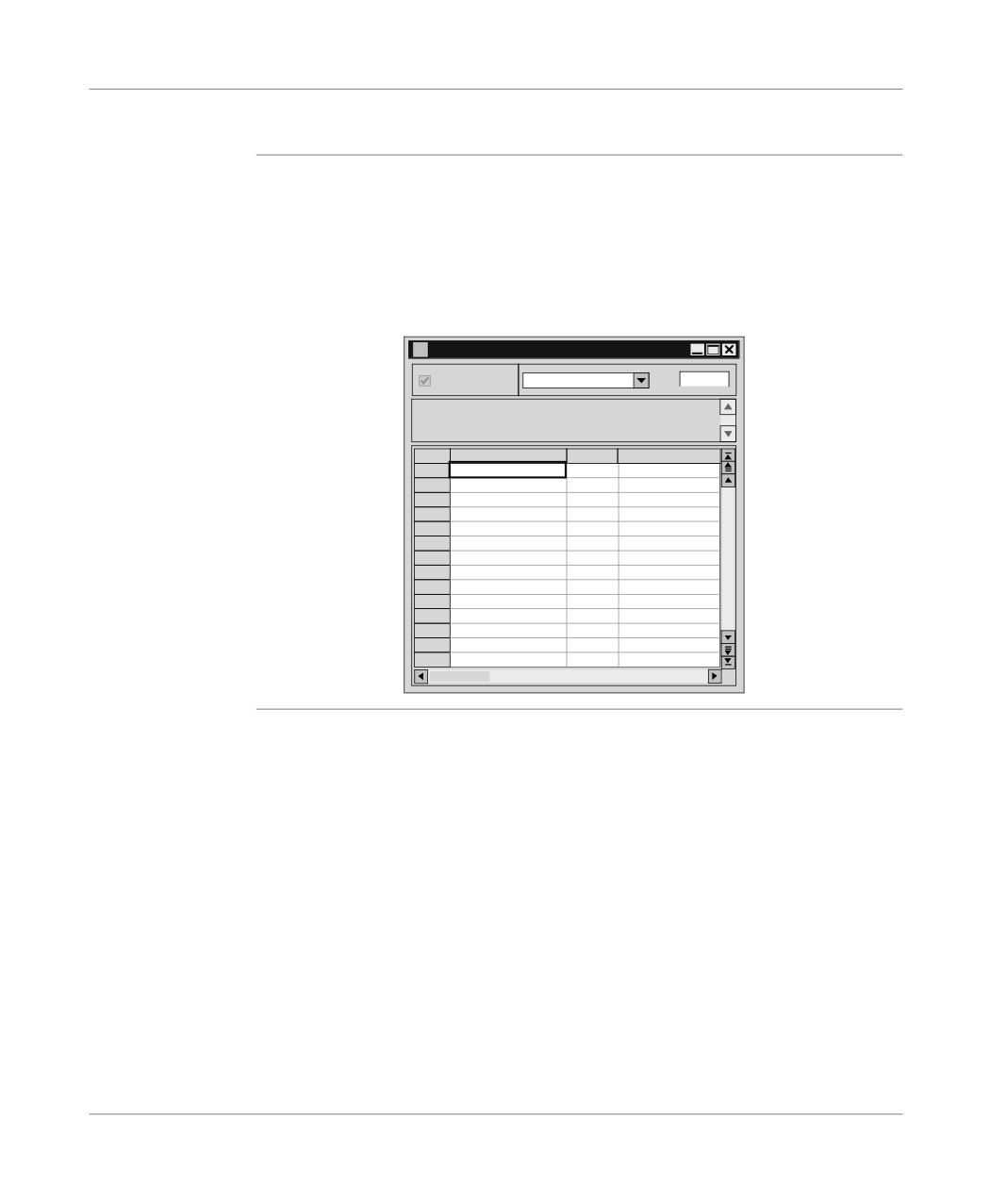
The variables used in the application (sections, subroutines, sequential tasks) are
variables used in
viewed in bold characters in the variables editor.
the application
For this, input the Options\Variables editor\Usage in the application command
before opening the variables editor.
Example:
Variables
parameters
MEMORY
DWORD
%MD0
Address
Type
Symbol
%MD0
DWORD
Presel_trem1_a
%MD1
DWORD
%MD2
DWORD
Presel_trem2_c
%MD3
DWORD
%MD4
DWORD
Presel_trem1_b
%MD5
DWORD
%MD6
DWORD
Presel_melang
%MD7
DWORD
%MD8
DWORD
Litres_tremie1
%MD9
DWORD
%MD10
DWORD
Litres_tremie2
%MD11
DWORD
%MD12
DWORD
Litres_melangeur
%MD13
DWORD
Display of
Overlapping is possible on the following variables:
variables with
l %MB,
overlapping
l %MW,
l %MD,
l %MF,
l %KB,
l %KW,
l %KD,
l %MF.
Example:
If %MW1 is used in the application, the overlapping is effective for:
l %MD1,
l %MF1,
l %MB2,
l %MB3.
235
Editing variables
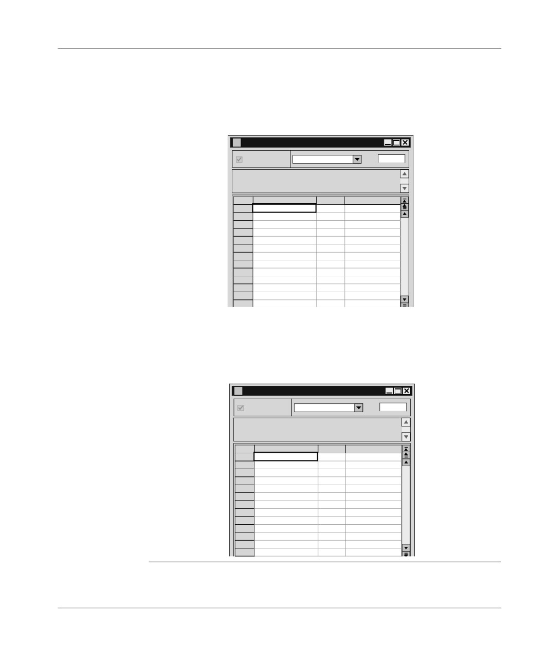
The overlapping is represented by displaying the variables in red characters and it
is managed providing that:
l the variables are used in the application program (Sections, subroutines, events),
l the Options\Variables editor\Overlapping command has been selected before
opening the variables editor.
Example:
Variables
parameters
MEMORY
DWORD
%MD0
Variable
Type
Symbol
%MD0
DWORD
Presel_trem1_a
%MD1
DWORD
%MD2
DWORD
Presel_trem2_c
%MD3
DWORD
%MD4
DWORD
Presel_trem1_b
%MD5
DWORD
%MD6
DWORD
Presel_melang
%MD7
DWORD
%MD8
DWORD
Litres_tremie1
%MD9
DWORD
%MD10
DWORD
Litres_tremie2
%MD11
DWORD
%MD12
DWORD
Litres_melangeur
Simultaneous display of the variables used in the application with overlapping is
possible by selecting the commands:
l Options\Variables editor\Overlapping,
l Options\Variables editor\Usage in the application.
Example:
Variables
parameters
MEMORY
DWORD
%MD0
Variable
Type
Symbol
%MD0
DWORD
Presel_trem1_a
%MD1
DWORD
%MD2
DWORD
Presel_trem2_c
%MD3
DWORD
%MD4
DWORD
Presel_trem1_b
%MD5
DWORD
%MD6
DWORD
Presel_melang
%MD7
DWORD
%MD8
DWORD
Litres_tremie1
%MD9
DWORD
%MD10
DWORD
Litres_tremie2
%MD11
DWORD
%MD12
DWORD
Litres_melangeur
236
Editing variables
Cutting/Copying/Pasting variables in a variables editor
Introduction
PL7 gives the option of Cutting or Pasting a selection of variables, within the vari-
ables editor.
How to Copy/
Carry out the following steps:
Paste a block of
Step
Action
variables in a
variables editor.
1
Select a block of variables by clicking and dragging from the first variable of the
block through the whole block, keeping the Shiftkey held down, in the far left
hand column of the variables editor.
2
Right click on the selection (contextual menu) and select Copy.
3
Place the cursor on the first variable in the block where the copied variables
are to be pasted.
4
Right click (contextual menu) and select Paste.
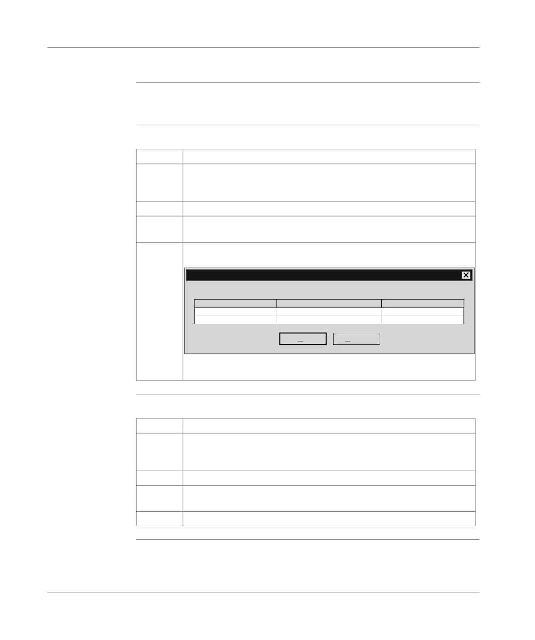
Result: the following window appears.
Paste
Please modify all symbols before confirming
Address
Symbol
Comment
%M56
Trig_sect_remp
Validation condition
%M57
Trig_sect_vidan_mix_a
Validation condition
OK
Cancel
All the variables duplicated in this way should be renamed before you Paste
them.
How to Cut/Paste
Carry out the following steps:
a block of
Step
Action
variables in a
1
Select a block of variables by clicking and dragging from the first variable of the
variables editor
block through the whole block, keeping the SHIFTkey held down, in the far left
hand column of the variables editor.
2
Right click (contextual menu) on the selection and select Cut.
3
Place the cursor on the first variable in the block where you want to paste the
copied variables.
4
Right click (contextual menu) and select Paste.
237
Editing variables
Entering/Modifying constants
Introduction
The variables editor is used to enter/modify/display all the variables with their pa-
rameters and attributes.
Procedure
Carry out the following operations:
Step
Action
1
Open the application browser.
2
Double left click on the Variables repertoire or select this with the arrows and
then press the right arrow.
3
Select the "CONSTANTS" variable type.
4
Select the variable format:
l BYTE (octet): example %KB26,
l WORD (16 bit constant): example %KW0,
l DWORD (32 bit constant): example %KD2,
l REAL (real 32 bit word): example %KF14.
5
Select the variable to be informed: example: %KW0.
6
Enter the symbol and press ENTER.
7
Enter the comment and press ENTER.
8
Select the Parameters option.
9
Select the entry/display base (optional):
10
Enter the value and press ENTER.
The syntax of the value automatically updates the associated base (e.g.: if
16#AA is entered -> the base goes to hexadecimal).
In the case of %KB messages:
l enter the chain of characters in quotes then press ENTER (e.g.: "Number
of parts"),
l To modify a message, select the %KB byte with the base ’Begin Mess.’.
11
Deselect the parameter option to close the parameter entry window.
238
Editing variables
Parametrizing predefined function blocks (FB)
Introduction
The predefined function blocks are:
l %TMi timer FB,
l %Ti Series 7 timer FB,
l %MNi Monostable FB.
l %Ci Counter/down counter FB,
l %Ri Register FB,
l %DRi Drum FB.
The %Ti, %MNi and %DRi FBs must be declared in advance in software configu-
ration.
The editor is used to enter/modify/display all the variables with their parameters
and attributes.
Procedure
Carry out the following actions:
Step
Action
1
Open the application browser.
2
Double left click on the Variables repertoire or select this with the arrows and
then press the right arrow.
3
Select the type: PRE-DEFINED FB .
4
Select the type of FB to be parametrized:
l Parametrizing %TMi (See Parametrizing %TMi, p. 240),
l Parametrizing %Ti (See Parametrizing the %Ti, p. 240),
l Parametrizing %MNi (See Parametrizing the %MNi, p. 240),
l Parametrizing %Ci (See Parametrizing the %Ci, p. 241),
l Parametrizing %Ri (See Parametrizing the %Ri, p. 241),
l Parametrizing %DRi (See Parametrizing the %DRi, p. 241),
239
Editing variables
Parametrizing
Carry out the following actions:
%TMi
Step
Action
1
Select the variable to be informed (e.g.: %TM0).
2
Enter the symbol and press ENTER.
3
Enter the comment and press ENTER.
4
Select the "parameters" option.
5
Enter the PRESET value (%TMi.P: 0 to 999) and press ENTER.
6
Select the operating mode of the block: TP,TON,TOF.
7
Select the value of the time base TB.
8
Select the Reg option depending on the case (Adjusting by terminal).
Parametrizing
Carry out the following actions:
the %Ti
Step
Action
1
Select the variable to be informed (e.g.: %T0).
2
Enter the symbol and press ENTER.
3
Enter the comment and press ENTER.
4
Select the "parameters" option.
5
Enter the PRESET value (%Ti.P) and press ENTER.
6
Select the value of the time base TB.
7
Select the Reg option depending on the case (Adjusting by terminal).
Parametrizing
Carry out the following actions:
the %MNi
Step
Action
1
Select the variable to be informed (e.g.: %MN0).
2
Enter the symbol and press ENTER.
3
Enter the comment and press ENTER.
4
Select the "parameters" option.
5
Enter the PRESET value (%MNi.P) and press ENTER.
6
Select the value of the time base TB.
7
Select the Reg option depending on the case (Adjusting by terminal).
240
Editing variables
Parametrizing
Carry out the following actions:
the %Ci
Step
Action
1
Select the variable to be informed (e.g.: %C0).
2
Enter the symbol and press ENTER.
3
Enter the comment and press ENTER.
4
Select the "parameters" option.
5
Enter the PRESET value (%Ci.P) and press ENTER.
6
Select the Reg option depending on the case (Adjusting by terminal).
Parametrizing
Carry out the following actions:
the %Ri
Step
Action
1
Select the variable to be informed (e.g.: %R0).
2
Enter the symbol and press ENTER.
3
Enter the comment and press ENTER.
4
Select the "parameters" option.
5
The length (1<LEN<255) of the registers can be modified in the software con-
figuration.
6
Select the operating mode of the block: LIFO,FIFO.
Parametrizing
Carry out the following actions:
the %DRi
Step
Action
1
Select the variable to be informed (e.g.: %DR0).
2
Enter the symbol and press ENTER.
3
Enter the comment and press ENTER.
4
Select the "parameters" option.
5
Select the number of steps NB (1 to16).
6
Select the value of the time base TB.
7
Select the STEPS field to define the bit status for each step.
1. Allocate a variable %Qi.j or %Mi to each bit.
2. Show the value of variable for each step by clicking on the value 0 or 1 (flip
flop).
241
Editing variables
Cop/Paste the
This function is used to Copy/Paste the parameters of one function block into one
pre-defined
or more other function blocks of the same family to avoid tiresome entering.
function block
parameters
Carry out the following actions:
Step:
Actions:
1
From the variables editor select the PRE-DEFINED FB type.
2
Select the desired FB family.
3
Select the FB to be copied by clicking to the left of the name (the line goes to
reverse video).
4
Select the Edit\Copy SFB parameters command or, using the contextual
menu Copy SFB parameters.
5
Select the target FB(s) by:
l clicking to the left of the name (for one FB),
l clicking to the left of the name + pressing the Shift key, and move the mouse
up or down (for several FBs).
6
Select the Edit\Paste SFB parameters command or, using the contextual
menu Paste SFB parameters.
Note:
The Paste function can only be done with consecutive objects.
242
Editing variables
Printing variables
Introduction
This heading is use to print the list(s) of variables with their parameters.
Procedure
Carry out the following actions:
Step
Action
1
In the variables editor select the type of variables you require.
2
Select the ascending order of printing with the command View → Variables
sorted by address or View → Variables sorted by symbols.
3
Configure printing using the command File → Configuring printing.
4
Select the command File → Print.
4
Select:
l "All" to print all the variables configured in the application with the various
parameters.
l "Current type" to print the variables of the selected type.
5
Confirm printing with OK.
243
Editing variables
Exporting/Importing variables
Refer to the "Debugging, adjusting, documentation and appendix" part Chapter
heading "Importing and exporting":
l See: Exporting variables, p. 357.
l See: Importing variables, p. 358.
244