PL7 JUNIOR/PRO Operate modes manual (Operate modes manual eng V4.0) - page 3
TSX Micro/TSX Premium: Configuring the application
Accessing the application configuration
Principle
The configuration software displays a supply module and the processor selected
when the application was set up.
The object of this function is to:
l replace the processor (if the one chosen at the beginning is not right),
l configure the processor,
l declare/parametrize the various input/output modules and integrated modules,
l enter the software configuration,
l enter the Grafcet configuration.
In on-line mode this function is used to:
l diagnose module faults,
l debug modules.
Procedure
Carry out the following actions:
Step
Action
1
From the Application browser, double left click on the repertoire "Configura-
tionor position the arrow keys on this and press the right arrow.
2
Select:
l Hardware configuration to access the module racks,
l Software configuration to define the software application parameters,
l Grafcet objects configuration to define the specific grafcet parameters for
the application.
3
To confirm the configuration entered use the command Edit/Confirm or in the
contextual menu Confirm or use the icon
Note:
The command Edit/ Cancel modifications (CTRL+Z) or the icon
cancels all
modifications made since the last confirmation.
85
TSX Micro/TSX Premium: Configuring the application
Configuring the racks
Introduction
A rack with a 0 address is compulsory. It contains the station processor.
Number of racks managed by the different processor types
Processor type
Number of racks managed
TSX/PCX/PMX 57-1x
Up to 2 racks
TSX/PCX/PMX 57-2x/3x
Up to 16 racks
For a station configured with TSX/PCX/PMX 57-2x/3x processors, it is not neces-
sary to use successive addresses. It is possible to configure one station with a rack
with a 0 address and one rack with a 7 address.
A configuration with several racks must contain one rack that can be extended to a
0 address.
86
TSX Micro/TSX Premium: Configuring the application
Extension racks
There are the following possibilities:
You want…..
then…..
and…..
adding a rack
select an empty address
select the desired rack from
the dialogue box displayed.
or the symbol
(rack EX) then the command
Edit/Add a rack
selecting a rack
Click on the white rectangle
containing the address of the
rack or on the white rectangle
associated with the EX rack, a
dotted frame will surround the
selected rack.
replacing a rack
double click on the white rect-
and select an extendible rack
angle containing the address
or not from the dialogue box
of the rack or on the white
displayed.
rectangle associated with the
EX rack
suppressing a rack
select the rack
press the Suppr key or select
the command Edit/Sup-
press the rack (suppressiing
the 0 rack is not possible.
Note:
The button
only appears for version V3.3 processors or later and for extend-
ible racks.
Changing a V3.3 -> V3.0 processor can be refused if there are extension racks.
87

TSX Micro/TSX Premium: Configuring the application
Configuring the supply modules
Introduction
The supply does not necessarily occupy the first position in a rack (the position fur-
thest to the left). This position has no address.
Double format supplies occupy not only the first position but the 0 address position.
In this case the processor is configured in the 1 address position.
Configuration
There are the following possibilities:
You want…..
then…..
and…..
select a module
click on the module.
adding a module
select the extreme left position
select a module from the dia-
of the rack then the command
logue box displayed.
Edit/ Add a module
replacing a module
select the module
select a module from the dia-
logue box displayed (it is not
possible to configure a double
format supply if the position is
already occupied).
suppressing a module
select the module
press the Suppr key or select
the command Edit/Suppress
the module.
moving a module
select the module
move the module without re-
leasing the mouse button (this
action is possible if the fur-
thest left position in another
rack is free).
copying a module
select the module
press the Ctrl key and move
the module without releasing
the mouse button (this action
is possible if the furthest left
position in another rack is
free).
88
TSX Micro/TSX Premium: Configuring the application
Choosing/Changing the processor
Choosing the
Choosing the processor is the first stage in setting up an application. This choice is
processor
reversible.
Carry out the following actions:
Step
Action
1
Select the commandFile/ New from the PL7 home screen.
2
Select the PLC type>PREMIUM TSX.
3
Select the processor type -> TSX57xx Vyy.
4
Select an extension memory card if necessary (PCMCIA).
5
Specify (depending on the processor configured) whether or not your applica-
tion contains Grafcet.
6
Click on OK.
Changing the
The configuration editor provides assistance when attempting to change the proces-
processor
sor. A message is sent out if the change is not authorized.
WARNING
When changing to a version V3.x processor
Using aV3.x processor in an application that has previously been con-
figured with a lower processor version leads to an irreversible change
in the application structure.
This conversion involves:
l the creation of program structure in sections,
l the automatic creation of the Grafcet section when the initial pro-
gram module is written in Grafcet language.
l the automatic replacement of TSX SCY 21600 modules, if there are
any in the configuration, with TSX SCY 21601 modules.
l an increase in the size of the application by approximately 10%,
which can cause the conversion to fail.
Failure to observe this precaution can result in severe injury or
equipment damage.
89
TSX Micro/TSX Premium: Configuring the application
Carry out the following actions:
Step
Action
1
Select the Edit/Change processor command.
2
Select the required processor.
3
Select a memory card if necessary.
4
Confirm and then click on OK or press ENTER.
Note:
It is possible to change the processor using the drop-down menu in the configuration
editor.
90

TSX Micro/TSX Premium: Configuring the application
Configuration of the processor
Procedure
Carry out the following actions:
Step
Action
1
From the application configurator, select position 0 or 1 from rack 0.
2
Select Open module from the context menu or double click on the processor.
3
Confirm, depending on the application, the RUN/STOP input (See RUN/STOP
input, p. 91).
4
Confirm, depending on the application, the Automatic startup in RUN (See
Automatic startup in RUN, p. 92).
5
Confirm, depending on the application, the memory protection, then, if need
be, enter the input dedicated to this function.
6
Confirm, depending on the application, the initialization of internal words
%MWi on Cold restart.
7
Select the type of memory card for processors with this option.
8
Select the type of MAST task execution:
l Cyclic
l Periodic: 3 to 255 ms (20 ms, default value).If the value is 0, execution will
be cyclic.
9
Enter the value of the watchdog (See Watchdog, p. 92) of the MAST task: 10
to 500 ms maximum (250ms, default value).
10
Enter, depending on the application, the value of the period of the FAST task:
2 to 255 ms maximum (5ms, default value).
11
Enter, depending on the application, the value of the FAST task watchdog: 10
to 500 ms maximum (100 ms, default value).
12
If necessary, select type of Fipio (See Fipio, p. 93) mode for the MAST task:
l Controlled mode:the task is timed by a period (MAST in periodic execu-
tion).
l Free mode: the task controlled variables are scanned in "Optimal" mode,
but the scanning period may be greater than the period of the task, while
still less than the task watchdog.
13
If necessary, select type of Fipio mode for the FAST task (Controlled mode,
Free mode).
14
Confirm using the command Edit/Confirm (CTRL + W) or using the icon
RUN/STOP input The input %I1.8 can be parameterized to control the PLC’s switching between RUN/
STOP in the following way:
91
TSX Micro/TSX Premium: Configuring the application
l %I1.8 = 1 -> the PLC switches to RUN (program executes),
l %I1.8 = 0 -> the PLC switches to STOP (program stops executing).
Retrieval is rising edge.
A STOP command via %I1.8 input has priority over a RUN command via terminal or
network command.
An error on the RUN/STOP input causes a switch to STOP.
Automatic
If this option is checked, the PLC will automatically switch to RUN during a cold start.
startup in RUN
If there is no memory card, the PLC starts up according to the contents of the pro-
cessor’s internal RAM.
ee
If a memory card is inserted, it is the contents of the card which defines the startup.
Memory
This option enables the application contained in the PLC to be protected against any
protection
attempt to alter it.
The protection is activated by setting the PLC input dedicated to this function to 1.
Watchdog
The period of master task execution, in cyclic or periodic operation, is controlled
by the PLC (watchdog) and must not exceed the value defined in Tmax configuration
(250ms by default, 500ms maximum, modulo 10ms).
If overflow should occur, the application is declared in error, which causes the PLC
to stop immediately:
l TSX Premium: supply alarm relay set to 0
Execution monitoring:
l %S11: indicates a watchdog overflow, it is positioned to 1 by the system, when
the cycle time becomes greater than the watchdog.
l %SW11: contains the value of the watchdog (in ms).
l %S19 (periodic operation): indicates a period overflow, it is positioned to 1 by
the system, when the cycle time becomes greater than the task period.
l %SW0 (periodic operation): this word contains the value of the period (in ms),
it is initialized on cold restart by the value defined at configuration, it can be
changed by the user.
92
TSX Micro/TSX Premium: Configuring the application
Fipio
The FIPIO bus allows 127 devices to be connected to the connection point which is
built into the processor.
The software PL7-Junior or PL7-PRO and the processors, TSX P 5725x / 35x /
45x, TPCX 57351x, and TPMX 57352 /452 are used to configure and monitor the
connected devices.
These devices can be any of the following:
l FIPIO agent PLCs,
l TBX TOR or ANA,
l Momentum TOR or ANA,
l CCX-17,
l ATV16/58/66,
l AS-i gateway TBX SAP10,
l devices which comply with FIPIO standard profiles,
l PCs.
93
TSX Micro/TSX Premium: Configuring the application
Configuring the module positions
Positioning a
Carry out the following actions:
module
Step
Action
1
Select the position of the module to be configured (using the mouse or arrow
keys). (The PgUp, PgDn, TAB and SHIFT+TAB keys are used to select a dif-
ferent rack).
2
Select the Edit/Add module command or double click on the position selected
(ENTERkey). A dialogue box is displayed showing a list by family of modules
that can be configured for the selected position
3
Select the family (using the mouse or arrow keys), the module (the TAB key is
used to move between the different fields) and confirm by OK.
Notes:
Double format modules (for example the TSX CAY41 movement module) only ap-
pear in the module list when both the position selected, and the position before or
after it (depending on type) are not occupied.
Position 0 can only be occupied by a double format supply module or processor.
Moving a module
Carry out the following actions:
Step
Action
1
Select the required module.
2
Move it to the new position while keeping the mouse button held down or se-
lect the Edit/Move a module command.
3
Select the Edit/Confirm command for the modifications to be taken into ac-
count.
Notes:
Objects linked to the module at the former address are:
l deleted then recreated automatically at the new address,
l replaced in the program and variables editor (except for animation tables and
runtime screens) by objects at the new address.
Symbols associated with objects from the moved module are reattached to the ob-
jects at the new address.
The module that has been moved keeps all its parameters.
The processor can only be moved into positions 0 and 1 of rack 0.
94

TSX Micro/TSX Premium: Configuring the application
If you move a discrete module whose channel has been configured in RUN/STOP
mode, the address of the RUN/STOP bit is not modified. You must ensure that the
RUN/STOP input corresponds to an valid address for a discrete input.
When the module addresses are used in an EF (e.g. SEND_REQ, READ_VAR,
etc.), they are not updated automatically.
Copying a
Carry out the following actions:
module
Step
Action
1
Select the required module.
2
hold down Ctrl and drag the copy to the new position or select the Edit/Copy
Module command.
3
Select the Edit/Confirm command for the modifications to be taken into ac-
count.
Notes:
The objects associated with a module with the old address are copied to the new
address.
The module that has been copied keeps all its parameters.
Duplicating a module associated with an event (at least one module channel is as-
sociated with oneevent) is impossible. One event cannot be associated with several
channels/modules at the same time.
Deleting a
Carry out the following actions:
module
Step
Action
1
Select the required module.
2
Select Edit/Delete or press the Del key.
3
Select the Edit/Confirm command for the modifications to be taken into ac-
count.
Notes
If no input/output modules are declared in the configuration, or if there are any for-
mat modules, the PL7 software gives access to the %Ix.0 to %Ix.15 bits and to the
%Qx.0 to %Qx.15 outputs for each position (even if the half format module con-
cerned has less inputs/outputs).
If there are any standard format modules, the PL7 software gives access to the
%Ix.0 to %Ix.31 input bits for odd positions and to the %Qx+1.0 to %Qx+1.31 output
bits for even positions (even if the standard format module concerned has less in-
puts/outputs).
95

TSX Micro/TSX Premium: Configuring the application
Configuring inputs/outputs for each module
Procedure
Carry out the following actions:
Step
Action
1
Select the module to be configured (using mouse or arrow keys).
2
Select the command Services/Open the module or double click on the mod-
ule selected.
A window is displayed indicating:
l the module reference and position,
l the configuration context (See Configuration context in progress , p. 97) in
progress.
3
Enter the parameters and confirm with the command Edit/Confirm (CTRL +
W).
To find out about the various parameters, refer to the job headings concerned.
Depending on whether the command View/ Module Zone is selected or not,
the display is different.
4
Close the window by pressing (CTRL+F4) and parametrize the next module.
Special case for
Carry out the following actions:
PCMCIA
Step
Action
communication
modules
1
Select the "Comm" position.
2
Double click or move the up/down arrows and press the ENTER key.
Special case for
Carry out the following actions:
FIPIO
Step
Action
communication
1
Select the "FIPIO" position.
modules
2
Double click or move the up/down arrows and press the ENTER key.
Special case for
Carry out the following actions:
integrated
Step
Action
Adjustment
1
Select the "Loops" position.
modules (PMX
57102)
2
Double click or move the up/down arrows and press the ENTER key.
96
TSX Micro/TSX Premium: Configuring the application
Configuration
The Configuration selection is used to set the module’s parameters.
context in
progress
Adjust can be selected for counting, movement and weighing modules and is used
to:
l set initial parameter values offline,
l modify these parameters on-line.
The Debugging selection (only accessible in on-line mode) is used, depending on
the module to:
l display the status of the inputs,
l display the module diagnostics and the channels,
l perform output writing.
97

TSX Micro/TSX Premium: Configuring the application
Software configuration of the application
Procedure
Carry out the following operations:
Step
Action
1
Double left click on the Configuration directory or select it using the arrow
keys, then press right arrow.
2
Select the Software configuration directory.
Software configuration is used to set the following for the application:
l the number of different types of function blocks,
l the number of register words,
l the number of %M internal bits,
l the number of %M internal words,
l the number of %KW constants.
3
For each of the fields to be modified, select the field and then enter the required
value (entry is controlled to prevent values greater than the maximum autho-
rized number (See Maximum number of authorized objects, p. 98)) from being
entered.
4
Confirm the configuration with the Edit/Confirm (Ctrl + W) command
Maximum
For each of the objects this number is:
number of
Objects
Maximum value
authorized
objects
%TMi timers
255
%Ti Series 7 timers
255
%MNi monostables
255
%Ci counters
255
%Ri registers
255
%DRi drums
255
Number of words per register
255
%Mi internal bits
depends on the processor
%MWi internal words
depends on the size of memory available
%KWi constants
depends on the size of memory available
98

TSX Micro/TSX Premium: Configuring the application
Configuring Grafcet objects
Introduction
Before configuring Grafcet objects the following action must be taken:
l the processor version (See Processor version, p. 100) used must support Grafcet
language,
l creation of the Grafcet section for >= V3.x processors.
Grafcet object configuration is used to set the following for the application:
l the number of macro steps,
l the number of (Chart + Macro steps),
l the number of active steps,
l the number of valid transitions.
Procedure
Carry out the following actions:
Step
Action
1
Double left click on the Configuration directory or select it using the arrow
keys, then press right arrow.
2
Select the Configure Grafcet Objects directory.
3
For each of the fields to be modified, select the field and then enter the required
value (a check is made so that entries higher than the maximum authorized
number (See Maximum number of authorized objects, p. 99) cannot be made).
4
Confirm the configuration with the command Edit/ Confirm (Ctrl + W)
Maximum
For each of the objects this number is:
number of
Objects
Maximum values
authorized
Number of steps (Chart)
250
objects
Number of Macro steps
64
Number of steps in Macro steps
250 per Macro step
Number of steps (Chart + Macro step)
1024
Number of active steps
250
Number of valid transitions
400
99
TSX Micro/TSX Premium: Configuring the application
Processor
Compatibility table:
version
V1.5 and V2.0 processors
If you are using Grafcet it must be declared when the application is set up.
This option cannot subsequently be changed.
V3.x and V4.0 processors
The choice of whether to use Grafcet is made when creating the Grafcet section.
100

Program access
5
Introduction
Subject of this
This chapter describes how to:
chapter
l Creating a program module.
l Access to a program module.
l Modifying a module program’s execution order.
What’s in this
This Chapter contains the following Maps:
Chapter?
Topic
Page
Introducing the application browser
102
Creating or importing an LD, IL, ST section
105
Creating or importing a Grafcet section
107
Creating or importing a subroutine (SR)
109
Creating or importing an event
110
Editing/emptying/suppressing a section, an event or a sub-program
111
Modifying the section execution order
112
Accessing the runtime screens editor
113
101
Program access
Introducing the application browser
General points
The application browser shows the contents of a PL7 application in two forms:
l the structure view,
l the function view.
Description
The structure view
The structure view shows the contents of a PL7 application. It is used to navigate
within an application and provides direct access:
l to configurations,
l to the program,
l to the DFBs contained in the application,
l to the data,
l to the animation tables,
l to certain parts of the documentation file (general information, title pages),
l to tools such as runtime screens.
Section execution order corresponds to display order, and this order can be modi-
fied.
Note: the default PL7 application directory is called STATION. This name can be
modified in the Application propertiesdialog box.
The function view
The function view is a representation of the application split up into functional mod-
ules.
This split does not take the order of their execution by the PLC into account.
WARNING
Only PL7 PRO can be used to set up functional modules on TSX/PMX/
PCS57 PLCs.
Failure to observe this precaution can result in severe injury or
equipment damage.
102
Program access
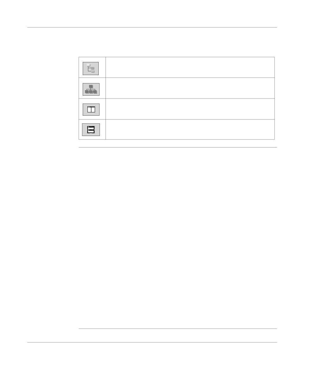
Navigation
The different browser application icons
between function
view and
structure view
Is used to display the application structure view.
Is used to display the application function view.
Is used to display the structure and function views in series.
Is used to display the structure and function views in parallel.
Application
The Properties function (which can be accessed from the Functional View of the
properties
Application Browser by right clicking on the application directory) at application
level is used to:
l provide the user with information on the current application,
l manage certain application parameters.
General tab
l application name (the application’s default name is STATION),
l type of processor used (cannot be modified),
l version number (0 to 127) and revision number (0 to 255) manually managed by
the user or automatically managed by the system on each save when a modifica-
tion has been made
l comments,
l save.
Protection tab
l application protection.
Identification tab
l creation date,
l date of last update,
l application ID.
Diagnostics tab
If the box is checked, the alarms generated by the diagnostics DFBs are saved in
the diagnostics buffer and can be viewed with the runtime screen viewer.
103

Program access
Identification,
This information can be accessed via theIdentification tab.
application IDs
The application is identified by a series of 8 numbers between 0 and 65535. Each of
these represents the signature of an application segment.
These signatures, which are automatically generated by the system, are used to au-
thenticate a given status of the application.
Each development of the application results in the modification of one or more sig-
natures.
Numbers and designations:
Number
Designation
0
Station ID (global application).
1
Local I/O configuration ID.
2
Remote I/O configuration ID.
3
PL7 application ID (code).
4
Reserved.
5
ID of constants.
6
Reserved.
7
Reserved.
104

Program access
Creating or importing an LD, IL, ST section
At a Glance
Creating a section is authorized in offline and online mode with the PLC in Run or
Stop mode.
Importing a section is authorized in offline and online mode with the PLC in Stop
mode.
Section
A section’s properties are as follows:
properties
l section name,
l associated task (only the MAST task supports Grafcet language),
l programming language used,
l execution condition (modifiable),
l comments,
l name of any associated functional module for PL7 Pro.
Note:
l the language can be modified if the section is not programmed,
l the language for a Grafcet section cannot be modified.
Display or
Carry out the following steps:
modify a
Step
Action
section’s
1
go to the section (in the Application Browser of the Structure view) and se-
properties
lect the Properties contextual menu (right click).
2
Carry out any necessary modifications.
3
Click on OK.
105

Program access
Creating a
Carry out the following actions:
section
Step
Action
1
Left click on the Section directory for the required task or position the cursor
over it using the arrow keys.
2
Via the contextual menu or using the Shift+F10 keys select Create.
3
Fill in the name: maximum 16 characters.
4
Select the language you would like to use to program the section.
5
Specify the Type of Protection:
l no protection,
l write protection,
l read/write protection.
6
Establish or if applicable modify the execution condition.
7
Where applicable select the functional module to be associated.
8
Where applicable enter the comment (250 characters max.).
This comment can be modified from a section’s "Properties" dialog box.
9
Click on OK.
Importing a
Carry out the following actions:
section
Step
Action
1
Left click on the Section directory of the required task or position the cursor
over it using the arrow keys.
2
Via the Context menu, the File menu or Shift+F10, select Import.
3
Select the file relating to the section to be imported.
4
Confirm with Open.
106
Program access
Creating or importing a Grafcet section
At a Glance
A Grafcet section can be created in offline and online mode with the PLC in Run or
Stop mode.
Importing a section is authorized in offline and online mode with the PLC in Stop
mode.
By default the creation of a Grafcet section generates three directories. These cor-
respond to:
l preliminary processing (Prl),
l sequential processing (Chart),
l posterior processing (Post).
The creation of a macro-step generates an additional directory.
PRL, POST
The properties are as follows:
Properties
l name,
l associated task,
l associated section,
l name of any associated functional module for PL7 Pro,
l programming language used (the language can be modified if the module is not
programmed),
l programmed attribute.
CHART, XM
The properties of a Grafcet module or macro-step are as follows:
Properties
l module or macro-step name,
l number of steps configured (during software configuration),
l programmed status (if the graph or macro-step are programmed),
l called status if the macro-step is called in the Chart,
l name of any associated functional module for PL7 Pro,
l a comment (max. 250 characters) visible while editing the documentation file.
For a macro-step:
l macro-step address and symbol,
l a comment associated with the macro-step (defined using the variable editor).
107

Program access
Creating a
Carry out the following actions:
section
Step
Action
1
Position the cursor over the section directory for the MAST, or FAST task using
a left mouse click or the arrow keys.
2
Using the contextual menu or the Shift+F10 keys select Create.
3
Enter the Name, 16 characters maximum.
4
Select the language Grafcet (non modifiable).
5
Specify the type of protection:
l no protection,
l write protection,
l read/write protection.
6
Establish or if applicable modify the execution condition.
7
Where applicable select the functional module to be associated.
8
Where applicable enter a comment (250 characters max.).
This comment can be modified from the Properties dialog box of a section.
9
Click on OK.
Notes:
A Grafcet section may not be created if the configuration is in the process of being
modified.
A Grafcet section may not be deleted:
l if a section module is in the process of being edited,
l or if the configuration is in the process of being modified.
Importing a
Carry out the following actions:
section
Step
Action
1
Position the cursor over the section directory for the MAST, or FAST task using
a left mouse click or the arrow keys.
2
Using the File menu, the contextual menu or the Shift+F10 keys, select Im-
port.
3
Select the file relating to the section to be imported.
4
Confirm with Open.
108

Program access
Creating or importing a subroutine (SR)
At a Glance
Creating a subroutine is authorized in offline and online mode with the PLC in Run
or Stop mode.
Importing a subroutine is authorized in offline and online mode with the PLC in Stop
mode.
SR properties
The properties are as follows:
l name,
l associated task,
l programming language used (the language can be modified if the module is not
programmed),
l programmed attribute,
l called or non-called attribute in the task,
l a comment associated with the subroutine (defined using the variable editor).
Creating a
Carry out the following actions:
subroutine
Step
Action
1
Left click on the SR directory of the required task or position the cursor over it
using the arrow keys.
2
Using the contextual menu or the Shift+F10 keys select Create.
3
Select the language in which the SR is to be programmed.
4
Click on OK.
Importing a
Carry out the following actions:
subroutine
Step
Action
1
Left click on the SR directory of the required task or position the cursor over it
using the arrow keys.
2
Using the contextual menu, the File menu or the Shift+F10 keys select Import.
3
Select the file relating to the SR to be imported.
4
Confirm with Open.
5
Enter the SR number.
6
Click on OK.
Note
A subroutine can be called from any section of its associated task, or from other sub-
routines of that task.
109

Program access
Creating or importing an event
At a Glance
Event creation is authorized in offline and online mode, with the PLC in Stop mode.
Importing an event is only authorized in offline mode.
Event Properties
The properties are as follows:
l name,
l associated task,
l name of any associated functional module for PL7 Pro,
l programming language used (the language can be modified if the module is not
programmed),
l programmed attribute,
l called or non-called attribute in the task.
Creating an
Carry out the following actions:
event
Step
Action
1
Left click on the Event directory or position the cursor over it using the arrow
keys.
2
Using the contextual menu select Create.
3
Select the language in which the event is to be programmed.
4
Where applicable select the functional module to be associated.
5
Click on OK.
Importing an
Carry out the following actions:
event
Step
Action
1
Left click on the Event directory or position the cursor over it using the arrow
keys.
2
Using the contextual menu or the File menu, select Import.
3
Select the file relating to the event to be imported.
4
Confirm with Open.
5
Enter the event number.
6
Where applicable select the functional module to be associated.
7
Click on OK.
110

Program access
Editing/emptying/suppressing a section, an event or a sub-program
Editing
Carry out the following:
Step
Action
1
Select the module (section, sub-program, event) required using the mouse or
the arrow keys.
2
Edit the module using the command contextual menu Open or double click or
key ENTER.
Emptying
Carry out the following:
Step
Action
1
Select the module (section, sub-program, event task) required using the
mouse or the arrow keys.
2
Select Edit/Empty, or use the command contextual menu Empty, or
(Shift+F10) Empty.
3
Confirm with YES.
Suppressing
Carry out the following:
Step
Action
1
Select the module (section, sub-program) required using the mouse or the ar-
row keys.
2
Select Edit/Suppress, or on the command contextual menu key Suppress, or
(Shift+F10) Suppress.
3
Confirm with YES.
Note:
It is not possible to perform a suppression operation on an event task.
111
Program access
Modifying the section execution order
Principles
This action can be carried out from within the same task from the structure view.
It is done in offline or online mode with the PLC in Stop mode.
Procedure
Carry out the following actions:
Step
Action
1
Left click (keeping the button held down) on the icon of the section to be
moved.
2
Move the section to the desired place.
WARNING
Running the program.
The program runs in the order shown in structure view.
The distribution of the sections, events and Grafcet modules in the var-
ious functional modules has no impact on the running of the program.
Failure to observe this precaution can result in severe injury or
equipment damage.
112
Program access
Accessing the runtime screens editor
At a Glance
Using PL7 you can access the runtime screens editor.
How to access
There are two potential scenarios:
the runtime
l The application does not contain runtime screens:
screens editor
Do the following:
Step
Action
1
Open the Application Browser.
2
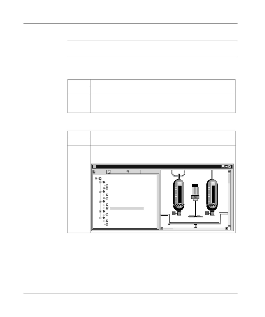
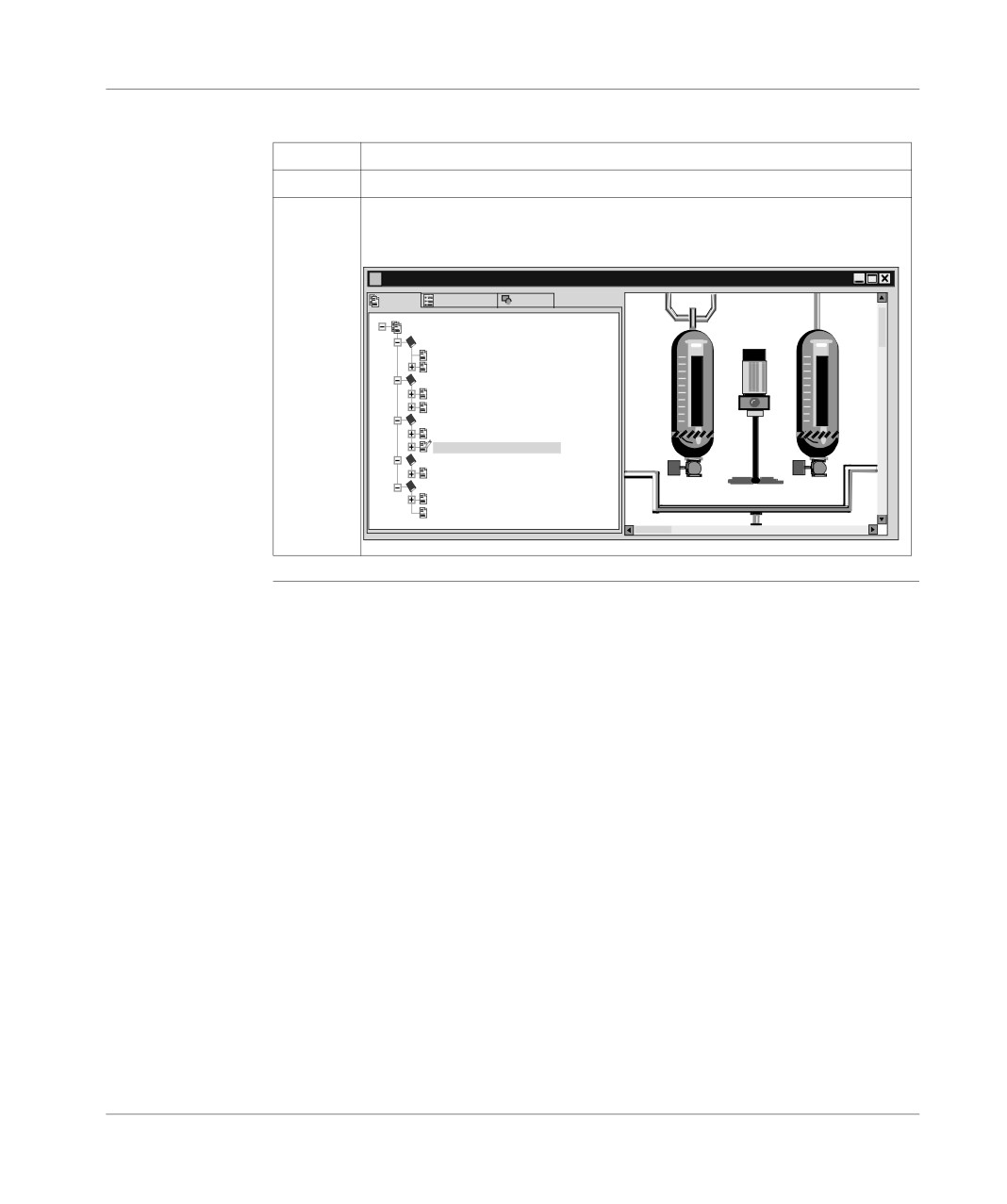
Double click on the Runtime screens directory from the structure view:
Result: The Runtime screens editor opens on a blank page, ready for the cre-
ation of a new screen or message.
l The application already contains runtime screens:
First scenario:
Step
Action
1
Open the Application Browser.
2
Double click on the Runtime screens directory from the structure view.
Result: the editor appears, displaying the last screen open before the previous
save:
Runtime Screens: BLEND_PRODUCTS - Product - Blend - Titration
Screens Messages Objects
Screen
WELCOME!
ie_1
Tré
3 - Read_me
1
1
1 - Welcome_screen
SYSTEM INFORMATION
7 - System bit
6 - Grafcet
TITRATION_PRODUCTS
0
0
2 - Screen_ monitoring
0 - Product_Blend_Titration
DIAGNOSTICS_APPLICA
8 - Monitoring_mixer
DFB BEHAVIOR
eur
4 - DFB_Screen - behavior
5 - Information_on_DFB_Debug
113
Program access
Second scenario:
Step
Action
1
Open the Application Browser.
2
Double click on the desired screen or message from the structure or func-
tion view.
Result: the editor displays the desired element immediately:
Runtime Screens: TITRATION_PRODUCTS - Product - Blend - Titration
Screens Messages
Objects
Screen
WELCOME!
ie_1
Tré
3 -Read_me
1
1
1 - Welcome_screen
SYSTEM INFORMATION
7 - System bit
6 - Grafcet
TITRATION_PRODUCTS
0
0
2 - Screen_monitoring
0- Product_Blend_Titration
DIAGNOSTICS_APPLICATION
8 - Monitoring_mixer
DFB BEHAVIOR
eur
4 - DFB_Screen - behavior
5 - Information_on_DFB_Debug
114

Programming in LD rung language
6
Introduction
Subject of this
This chapter reminds you of the structure of a program in rung language.
chapter
It describes:
l How to create a program.
l How to use the different functions offered by the editor.
l How to manage the different modules making up the application.
What’s in this
This Chapter contains the following Maps:
Chapter?
Topic
Page
Structure of a program in Ladder language
117
Creating a Ladder program
119
Specific input
121
Modifying a network of contacts
122
Displaying variables as symbols or addresses
127
Information box
129
Online symbolization
130
Input of a predefined function block (Ladder editor)
131
Function library
134
Operate block entry
136
Horizontal and vertical block entry
138
Assisted entry of a library function or of an instance of DFB type (Ladder editor)
139
Direct access to a subroutine
142
Replacing a variable in the application
143
Cross Referencing a variable in an application
145
115
Programming in rung language
Topic
Page
Animation of the Ladder program elements
148
Printing of a program
149
Export/Import of source files
150
116
Programming in rung language
Structure of a program in Ladder language
Principal
A program written in ladder language is composed of a series of networks executed
sequentially by the PLC.
Laid out between two potential bars, a network is a group of graphical elements
linked to each other by horizontal and vertical links. These elements represent:
l The PLC’s inputs/outputs (push-buttons, sensors, relays, indicators…).
l Automation functions (timers, counters…).
l Arithmetic and logical operations and transfer operations.
l The PLC’s internal variables.
Each network (known as a Rung) is made up of:
l A label input area (cell situated in the top left of the rung).
l A comment input area (first line to the right of the label).
l A (Test and Action) input area for graphical elements:
l
7 lines and 11 columns (maximum size) for a level L1 application.
l
16 lines and 11 columns (maximum size) for a level L2 application
The Test area (columns 1 to 10) accommodates:
l Contacts.
l Function blocks.
l Comparison blocks.
The Action (column 11) accommodates:
l Coils.
l Operate blocks.
117
Programming in rung language
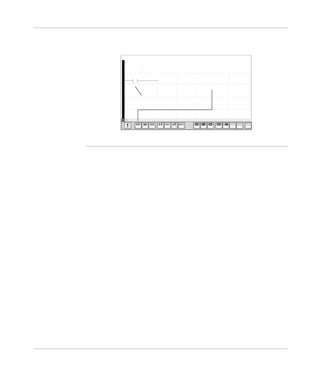
Example
Network (Rung).
Label
Comment
(*Verifying start group authorization*)
%1
%I 1.1
1- Select element from the
graphics palette
2- Place element
on the input grid
P
N
S
R
OPER
COHP
COHP
H
V
F2
F3
F4
F5
F6
F7
F8
F9
F10
F11
F12
S.F2
S.F3
S.F4
S.F5
118
Programming in rung language
Creating a Ladder program
Procedure
Carry out the following actions:
Step
Action
1
Creating or importing an LD, IL, ST section, p. 105.
2
Enter the label %Li (optional).
Double click on the label area, or put the cursor in the area and press the
Space bar, then confirm using Enter.
3
Enter the comment (optional).
Double click on the comment area, or put the cursor in the area and press the
Space bar, then confirm using Enter.
4
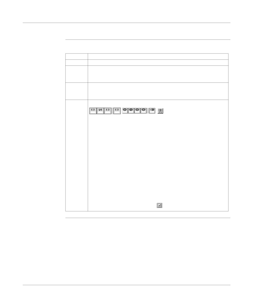
Enter the graphical elements:
P
S
R
F2
F3
F4
F5N
F9
F10
F11
F12
I F2
Using the mouse:
1. Click on the graphical element situated in the graphical palette.
2. Click on the grid at the required place.
3. Enter the corresponding variable (by default enter with comment mode is
active) and confirm using ENTER.
Using the keyboard:
1. Move the cursor over the grid to the required place.
2. Press the function key corresponding to the graphical element situated in
the graphical palette to be inserted.
3. Enter the corresponding variable (by default enter with comment mode is
active) and confirm using ENTER.
4. Confirm the networks of contacts using the ENTER key, or using the com-
mand Edit/Confirm or using the icon
119
Programming in rung language
Moving within
The possible moves are:
the editor
l From cell to cell: arrow keys.
l To the first column of the Rung: Home key.
l To the last column of the Rung: End key.
l To the next page: Page Down key.
l To the previous page: Page Up key.
l To the start of the module: Ctrl+Home keys.
l To the end of the module: Ctrl+End keys.
Notes
The software offers 2 input modes for a network of contacts:
l Without comments: allows you as a first step to build the network of contacts
without commenting the graphical elements and to comment them once the
graphics are completed.
l With comments: menu Edit/Enter with comments.
If an error is detected during validation, the rung stays red, if none are detected, the
variables associated to the graphical elements are blue.
120
Programming in rung language
Specific input
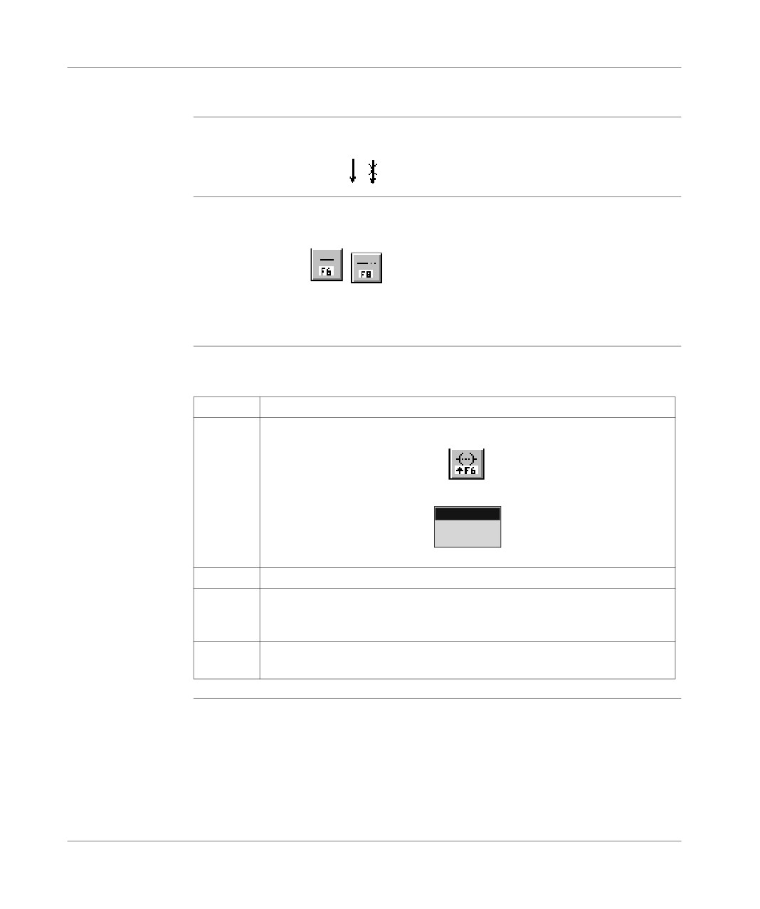
Input/Deletion of Select the cell situated at the top and to the right of the connection then click on the
the vertical links.
key F7 or click on the icon
and position the cursor in the created cell
Input/Deletion of
Input:
horizontal
Select the cell where the link must be positioned and then click on the key F6 or F8
connections
or click on the icons
and position the cursor in the created cell.
Deletion:
select the required cell or cells then press the key Del or on the Contextual menu
choose the command Delete.
Inputting the
Inputting instructions HALT (end of program), RETURN (return to the calling pro-
codes: HALT,
gram), CALL (subroutine call) operates following the procedure:
RETURN and
Step
Action
CALL
1
Click on the icon positioned in the graphic palette, the choice window appears.
HALT
CALL
RETURN
2
Select the required code and confirm with ENTER.
3
Place the cursor symbolizing the chosen code in the zone Action and click (in
the case of a keyboard entry, the cursor should be positioned in the Action
zone beforehand).
4
With codes, confirmation is direct HALT and RETURN. For the call, input the
SR number (sub-routine created beforehand) and confirm with ENTER.
121
Programming in rung language
Modifying a network of contacts
Accessing a
The program module being displayed, select the command Edit/Go to/Rung
network (Rung)
(Crtl+A) or the icon
The possible choices are as follows:
Select in the label field…
position…
TOP
at the beginning of the program module.
BUTTOM
at the end of the program module.
%Li
at the corresponding label number.
The Move zone allows a movement relative to TOP/BUTTOM/%Li.
Selecting one or
The possible choices are as follows:
several
Select…
by…
or…
networks (Rung)
one network
positioning the cursor over the Rung
by clicking to the left of the gray ver-
and selecting the command Edit/
tical bar.
Rung selection mode.
several net-
1. positioning the cursor on the first
by clicking to the left of the gray ver-
works
or the last Rung to be selected and
tical bar.
by selecting the command Edit/
Rung selection mode.
2. then by moving the mouse while
by pressing the SHIFT key and the
keeping the left button down to se-
arrow, Page Up or Page Down keys.
lect the other rungs.
Note:
The display of each selected rung is implemented by means of a rectangle equipped
with 8 handles.
122
Programming in rung language
Selecting one or
This function supports operations on elements such as cut, copy, paste, move, de-
several graphical
lete, initialize an animation table or initialize a table of cross references.
elements
The possible choices are as follows:
Select…
by…
or…
an element
left mouse click on the element
positioning the cursor over it using
the arrow keys.
a group of ele-
a left mouse click on the start cell
ments
(keep the mouse button down) then
move the cursor towards the end
cell,
Note:
Acknowledgement of an element is shown by a rectangle equipped with 8 handles.
Modifying a
Modifying a variable:
network (Rung)
Step
Action
1
Position the cursor over the variable to be modified then press the Space bar
or double click on the variable to be modified (except for SRs and DFB types).
2
Enter the modification (Escape cancels the current modification) and confirm
the entry using ENTER.
3
Confirm the modification using the keys (CTRL+W) or click on the icon
123
Programming in rung language
Modifying a contact in a network:
Step
Action
1
Using the keyboard:
Position the cursor over the cell containing the element to be modified.
Using the mouse:
Select the graphical element in the graphical palette by clicking on the required
element.
2
Using the keyboard:
Select the graphical element in the graphical palette using the keys F2 to F12
and SHIFT+F2 to F8 and confirm the entry using ENTER.
Using the mouse:
Position the cursor over the cell containing the element to be modified and con-
firm using ENTER.
3
Confirm using ENTER or select the command Edit/Confirm (CTRL+W) or
click on the icon
Canceling a modification:
To cancel a current modification on a network of contacts, select the command Edit/
Cancel modifications or click on the icon
Deleting an element from a rung:
The command Edit/Delete or the Delete key deletes the element and/or rung se-
lected.
Moving to a current modification which is not visible on the screen:
Select the command Edit/ Go to current modification .
124