PL7 JUNIOR/PRO Operate modes manual (Operate modes manual eng V4.0) - page 1
Related Documentation
Related Documentation
At a Glance
This manual consists of 3 sections:
l Part 1: General points on operate modes.
l Part 2: Configuration and programming.
l Part 3: Debugging, adjustment, documentation and appendices.
3
Table of Contents
About the book
13
Part I
Operating modes, general points
15
Presentation
15
Chapter 1
Setting up
17
Presentation
17
General points on PL7 software
18
Connections
20
Software installation
21
Chapter 2
Presentation of PL7 functions
27
Presentation
27
Configuration editor
28
Variables editor
29
Editing in ladder language
30
Instruction list language editing
31
Structured text language editor
32
Grafcet language editor
33
Animation tables
34
Debugging
35
Diagnostics
37
Operating screens
39
Structure of the documentation file
40
General software ergonomics
41
Chapter 3
Managing applications
45
Presentation
45
PL7 access security management
46
Accessing PL7 software
47
Creating an application
48
Opening an application
49
Protecting an application on a PLC
50
Saving an application
53
Offline/online operation
54
5
Transferring a program from a PC to the PLC or vice versa
55
Transferring data from file to PLC and vice versa
57
Comparing applications
58
Backing up in the internal Eprom Flash memory
59
Backing up on a TSX MFP BAK 032P memory card
60
Accessing a PL7 through a network
62
Memory Usage
63
Sending a command to the PL7
65
Part II
Configuration and Programming
67
Introduction
67
Chapter 4
TSX Micro and TSX Premium: Configuring
69
At a Glance
69
4.1
TSX-Micro
71
At a glance
71
Accessing the application configuration
72
Choosing/Changing the processor
73
Configuring the processor
75
Configuring the module positions
78
Configuring inputs/ outputs for each module
80
Software configuration of the application
81
Configuring Grafcet objects
82
4.2
TSX Premium
84
At a glance
84
Accessing the application configuration
85
Configuring the racks
86
Configuring the supply modules
88
Choosing/Changing the processor
89
Configuration of the processor
91
Configuring the module positions
94
Configuring inputs/outputs for each module
96
Software configuration of the application
98
Configuring Grafcet objects
99
Chapter 5
Program access
101
Introduction
101
Introducing the application browser
102
Creating or importing an LD, IL, ST section
105
Creating or importing a Grafcet section
107
Creating or importing a subroutine (SR)
109
Creating or importing an event
110
Editing/emptying/suppressing a section, an event or a sub-program
111
Modifying the section execution order
112
Accessing the runtime screens editor
113
6
Chapter 6
Programming in LD rung language
115
Introduction
115
Structure of a program in Ladder language
117
Creating a Ladder program
119
Specific input
121
Modifying a network of contacts
122
Displaying variables as symbols or addresses
127
Information box
129
Online symbolization
130
Input of a predefined function block (Ladder editor)
131
Function library
134
Operate block entry
136
Horizontal and vertical block entry
138
Assisted entry of a library function or of an instance of DFB type (Ladder editor)
139
Direct access to a subroutine
142
Replacing a variable in the application
143
Cross Referencing a variable in an application
145
Animation of the Ladder program elements
148
Printing of a program
149
Export/Import of source files
150
Chapter 7
Programming instruction list in LIST language
151
Introduction
151
Structure of an Instruction List program
152
Creating a program in Instruction List
153
Accessing a statement or instruction (Instruction List)
154
Displaying variables as symbols or addresses
157
Information box
158
Online symbolization
159
Input of a predefined function block (List editor)
160
Assisted entry of a library function (List editor)
161
Direct access to a subroutine
163
Replacing a variable in the application
164
Cross Referencing a variable in an application
166
Animation of List program elements
169
Printing of a program
170
Export/Import of source files
171
Chapter 8
Programming in Structured Text ST language
173
Introduction
173
Structure of a program in Structured Text language
174
Creating a program in Structured Text (ST)
175
Modifying a Structured Text program
176
Displaying variables as symbols or addresses
179
Information box
180
7
Online symbolization
181
Input of a predefined function block (ST editor)
182
Assisted entry of a library function (ST editor)
183
Direct access to a subroutine
185
Replacing a variable in the application
186
Cross Referencing a variable in an application
188
Animation of Structured text program elements
191
Printing of a program
192
Export/Import of source files
193
Chapter 9
Programming in Grafcet language
195
Introduction
195
Designing a program in Grafcet language
196
Structure of a Grafcet page
197
Grafcet graphic objects
198
Creating a Grafcet module
203
Modifying a Grafcet program
216
Replacing a variable in the application
219
Cross Referencing a variable in an application
221
Animation of Grafcet program elements
224
Printing of a program
225
Export/Import of source files
226
Chapter 10
Editing variables
227
Introduction
227
Accessing the variables editor
228
Input/Modification/Suppression of symbols and comments
229
Objects associated with a variable
231
Presymbolization
232
Sorting variables by symbols or addresses
234
Displaying variables in the editor
235
Cutting/Copying/Pasting variables in a variables editor
237
Entering/Modifying constants
238
Parametrizing predefined function blocks (FB)
239
Printing variables
243
Exporting/Importing variables
244
Chapter 11
Function modules
245
Presentation
245
Function modules
246
Properties of a function module
247
Creating a functional module
248
Programming a functional module
249
Debugging a functional module
250
Detaching/Deleting a functional module
251
Export of a functional module
254
8
Importing a functional module
255
Creating, deleting, moving, dragging and dropping an animation table in a functional
module
256
Chapter 12
DFB function blocks
259
Presentation
259
DFB types
260
Creating a DFB type
261
Programming a DFB type
262
DFB type instance
265
Running a DFB instance
267
Entering a DFB instance
268
How to protect a DFB
269
How to Import/Export a DFB type or an application containing DFB types
270
Part III
Debugging, adjustment, documentation and ap-
pendices
271
Introduction
271
Chapter 13
Debugging
273
Introduction
273
Introduction to the PLC debugging screen
275
CPU screen designation zone
276
Information zone
277
Task Zones
278
Operating mode zone
280
Event zone
281
Last stop zone
282
Realtime clock zone
283
Modification of the program in Run mode
284
Animating program elements
285
Grafcet debugging
288
Executing the programme
291
Task properties
292
Executing the MAST task
293
Executing the FAST task
295
Execution of a program with breakpoint
297
Executing a program in step by step mode
300
Forcing TOR input
302
Forcing analog inputs, TSX Micro
303
Forcing analog inputs, TSX Premium
304
Adjustment of the application specific functions
305
Debugging a functional module
306
Debugging DFBs
308
9
Chapter 14
Adjustment of variables
309
Introduction
309
Animation of variables: creating Animation tables
310
Working with animation tables
312
Animation and modification of the variables: DFBs
314
Modification of the variables:
316
List of forced bits
317
Chapter 15
Diagnostic functions
321
Introduction
321
Diagnostic of the PLC’s last stop
322
Module/channel diagnostics
323
Program diagnostics
324
Module call stacks
326
Diagnostics DFBs
327
Implementation of diagnostics DFB
328
DFB diagnostics error messages
329
Chapter 16
Documentation
333
Presentation
333
Contents of documentation file
334
Documentation: application documentation file
337
Chapter 17
Import/Export
341
Introduction
341
General points on import/export
343
Import/Export source files
344
Exporting a Section , a Subroutine, an Event
351
Importing a Grafcet/Ladder/List/Structured text section
353
Exporting an LD, IL, ST, Grafcet source file
354
Importing an LD, IL, ST, Grafcet source file
355
Exporting variables
357
Importing variables
358
Importing/Exporting variables in EXCEL format
360
Exporting a functional module
362
Importing a functional module
364
Importing a functional module using the wizard
366
Exporting animation table(s)
369
Importing animation table(s)
371
Export of runtime screens
373
Import of runtime screens
375
Export of a DFB type
376
Importing a DFB type
378
Exporting an application
380
Importing an application
382
Exporting an application in FNES format (Input/Output Neutral File)
. 384
10
Importing an application in FNES format
385
Chapter 18
Configuring the Uni-telway link
387
Introduction
387
General
388
Configuration of the terminal/PLC link
390
Advanced configuration
396
Chapter 19
Configuring the FIPWAY link
399
Presentation
399
General
400
Configuring the terminal/FIPWAY link
402
Advanced Configuration
406
Chapter 20
OS Loader
409
Introduction
409
The OS Loader: At a Glance
410
Displaying the PLC OS version
412
Downloading an OS
413
Communication error during downloading
414
Limitations of the OS Loader
415
Chapter 21
Windows
417
Presentation
417
PL7 online help
418
Help Topics Browser
419
PL7 contextual Help
421
General points relating to Windows
422
Equivalent Windows keyboard: Basic principle
423
The menu keys
424
Windows dialogue box keys
425
Keys for modifying text
427
Text selection keys
428
Work station and Windows Explorer keys
429
Print management in Windows
430
Glossary
. . . . . . . . . . . . . 431
Index
. . . . . . . . . . . . . 439
11
12
About the book
At a Glance
Document Scope This manual describes the installation of software for Micro and Premium PLCs
Validity Note
The update of this documentation takes into account the functions of PL7 V4.0
Nevertheless, it can be used to set up previous versions of PL7.
User Comments We welcome your comments about this document. You can reach us by e-mail at
TECHCOMM@modicon.com
13
About the book
14
Operating modes, general points
I
Presentation
Subject of this
This spacer describes how to set up the software tool and gives general points on
part
managing applications.
What’s in this
This Part contains the following Chapters:
part?
Chapter
Chaptername
Page
1
Setting up
17
2
Presentation of PL7 functions
27
3
Managing applications
45
15
Operating modes, general points
16
Setting up
1
Presentation
What’s in this
This chapter describes the software set up for the programming software.
chapter
What’s in this
This Chapter contains the following Maps:
Chapter?
Topic
Page
General points on PL7 software
18
Connections
20
Software installation
21
17
Setting up
General points on PL7 software
At a Glance
PL7 Micro/Junior/Pro are programming and debugging tools for TSX Micro and TSX
Premium PLCs.
There are three software variants:
l the software suite that is used to install PL7 software,
l the software update suite that is used to update a previous version to a new ver-
sion (Pl7 Micro V1.0 to P17 Micro V4.0),
l the software upgrade suite that is used to upgrade a previous version to a new
version with a higher level of functionality (PL7 Micro V1.0 to P17 Junior V4.0, or
PL7 Junior V1.0 to PL7 Pro V4.0).
A PL7 software suite comprises:
l a PL7 software installation CD-ROM,
l a CD-ROM containing the previous version of the TSX37 and TSX57 processor
operating systems,
l a TSX07/37/57 PC UNI-TE terminal port cable (reference TSX PCU 1030, not
supplied with updates or upgrades),
l an installation and start up guide for PL7,
l a product identification number.A record of this number should be kept because
it is needed each time the corresponding software is installed,
l a CD containing documentation in French/English/German/Italian/Spanish.
Functions
The functions of PL7 software are as follows:
Pl7-Micro
Pl7-Junior
Pl7-Pro
Programming
TSX-Micro
TSX-Micro\Premium
TSX-Micro\Premium
Grafcet Chart
yes
yes
yes
Grafcet Macro
no
TSX Premium
TSX Premium
Ladder
yes
yes
yes
List
yes
yes
yes
Structured text
no
yes
yes
Sections
yes
yes
yes
Functional mod-
no
no
yes
ules
Debugging
yes
yes
yes
Adjustments
yes
yes
yes
Diagnostics
yes
yes
yes
Runtime screens
no
no
creation/use
18
Setting up
DFB types
no
use
creation/use
DFB diagnostics
no
no
TSX/PCX/PMX57
Storage of PLC
TSX Premium
TSX Premium
symbols
Application docu-
yes
yes
yes
mentation file
References
TLX CD PL7M P 40 M: PL7-Micro
TLX CD PL7J P 40 M: PL7-Junior
TLX CD PL7P P 40 M: PL7-Pro
TLX RCD PL7M P 40 M: Update for PL7 Micro to the new version
TLX RCD PL7J P 40 M: Update for PL7 Junior to the new version
TLX RCD PL7P P 40 M: Update for PL7 Pro to the new version
TLX UCD PL7J P 40 M: Upgrade for PL7 Micro to the new version of PL7 Junior
TLX UCD PL7P P 40 M: Upgrade for PL7 Junior to the new version of PL7 Pro
19
Setting up
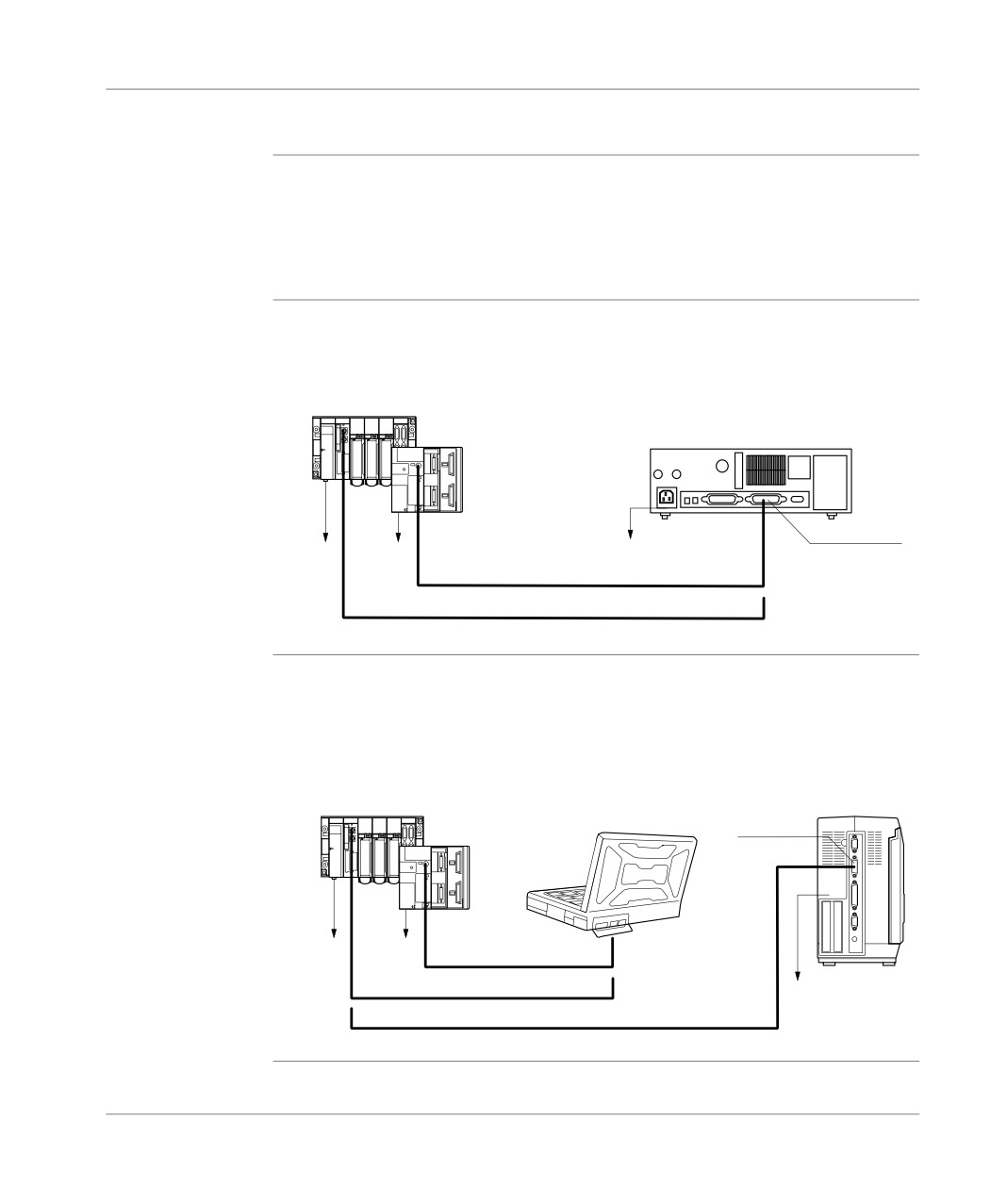
Connections
Introduction
This module deals with linking the terminal to the PL7 by cable. The specific links to
the terminal (monitor, keyboard, mouse, printer, power) are described in the con-
struction documentation.
Other connection methods are possible such as UNITELWAY bus, modem (via the
telephone network).
Connection from
Connecting a PC type terminal means using a TSX PCU 1030 link cable 2.5 metres
the PC <-> to the
long which is supplied with new software packages (not supplied with updates or up-
PL7
grades).
TSX 57
TSX 37
PC
Secteur
Secteur
Secteur
TSX PCU 1030
TSX PCU 1030
Connection of
Connecting an FTX 517 terminal requires a T FTX CBF 020 link cable 2.5 metres
FTX517/FT2000
long.
<-> to the PL7
Connecting an FT 2000 terminal requires a TSX PCU 1030 link cable 2.5 metres
long which is supplied with new software packages (not supplied with updates or up-
grades).
TSX 57
FTX 517
FT 2000
Connecteur
TSX 37
liaison série
Secteur
Secteur
TSX PCU 1030
TSX PCU 1030
Secteur
T FTX CBF 020
20
Setting up
Software installation
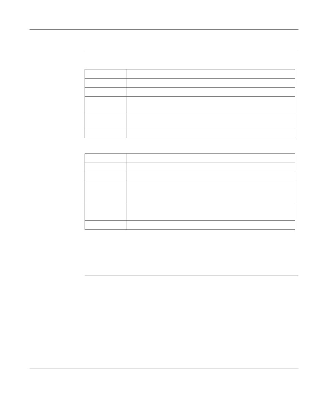
Configuring the
Nominal configuration
terminal
Processor
Pentium 133MHz
System
Windows 95\98 or Windows NT 4.0
Ram
64 Mb
Drives
Hard disk 50 Mb for P17 + 25 Mb for temporary directories
Disks
Ports
COM serial ports available for PLC connection (COM 1 to COM 4)
Parallel ports for printing (LPT1 to LPT4)
Monitor
VGA
Typical configuration
Processor
Pentium 266MHz
System
Windows 95\98 or Windows NT 4.0
Ram
128 Mb
Drives
Hard disk 50 Mb for P17 + 25 Mb for temporary directories
Disks
CD-ROM
Ports
COM serial ports available for PLC connection (COM 1 to COM 4)
Parallel ports for printing (LPT1 to LPT4)
Monitor
VGA or above (SVGA with 24 bit color management recommended).
Note:
These characteristics are for configurations for the installation of the PL7 software
only.
A larger configuration may be necessary if it is to be used at the same time as other
software.
21
Setting up
Contents of PL7
You can choose which components of the PL7 software you wish to install. The stan-
dard installation is the most straightforward, but a customized installation allows you
to optimize the space taken up by the software.
Contents of a standard installation (in bold):
Software
Contents
PL7-Micro
Core, function library, Uni-Telway driver.
Servers (security management).
Demonstration application.
FIP drivers
PL7-2 converter
PL7-Junior
Core, function library, Uni-Telway driver.
Servers (security management).
Demonstration application.
FIP drivers
PL7-2 converter
PL7-3 converter
S1000 converter
PL7-Pro
Core, function library, Uni-Telway driver.
Servers (security management).
Demonstration application.
FIP drivers
FNES Import/Export function
PL7-2 converter
PL7-3 converter
S1000 converter
22
Setting up
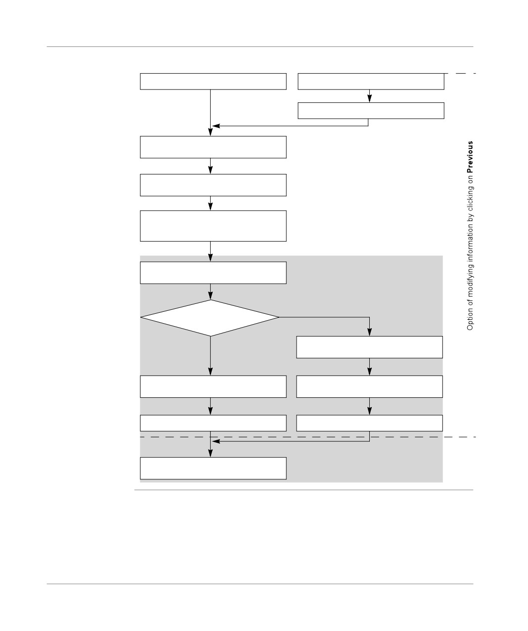
Installation
This procedure describes the various stages for PL7 software installation.
Insert the CD-ROM
Insert the first disk
Launch the Setup.exe file
Confirm the first screen
via Next
Choose the software language
then confirm via Next
Enter the product identification number
then confirm via Next
(a maximum of 3 entry attempts)
common to all installations
Save your coordinates
then confirm via OK
Select:
Customized
the type of installation
Select the elements to be installed and
Standard
confirm via Next
Define an installation path then confirm via
Define the various installation
Next
paths and then confirm via Next
Confirm the information via Next
Confirm the information via Next
Exit the installation via
Return to Windows
23
Setting up
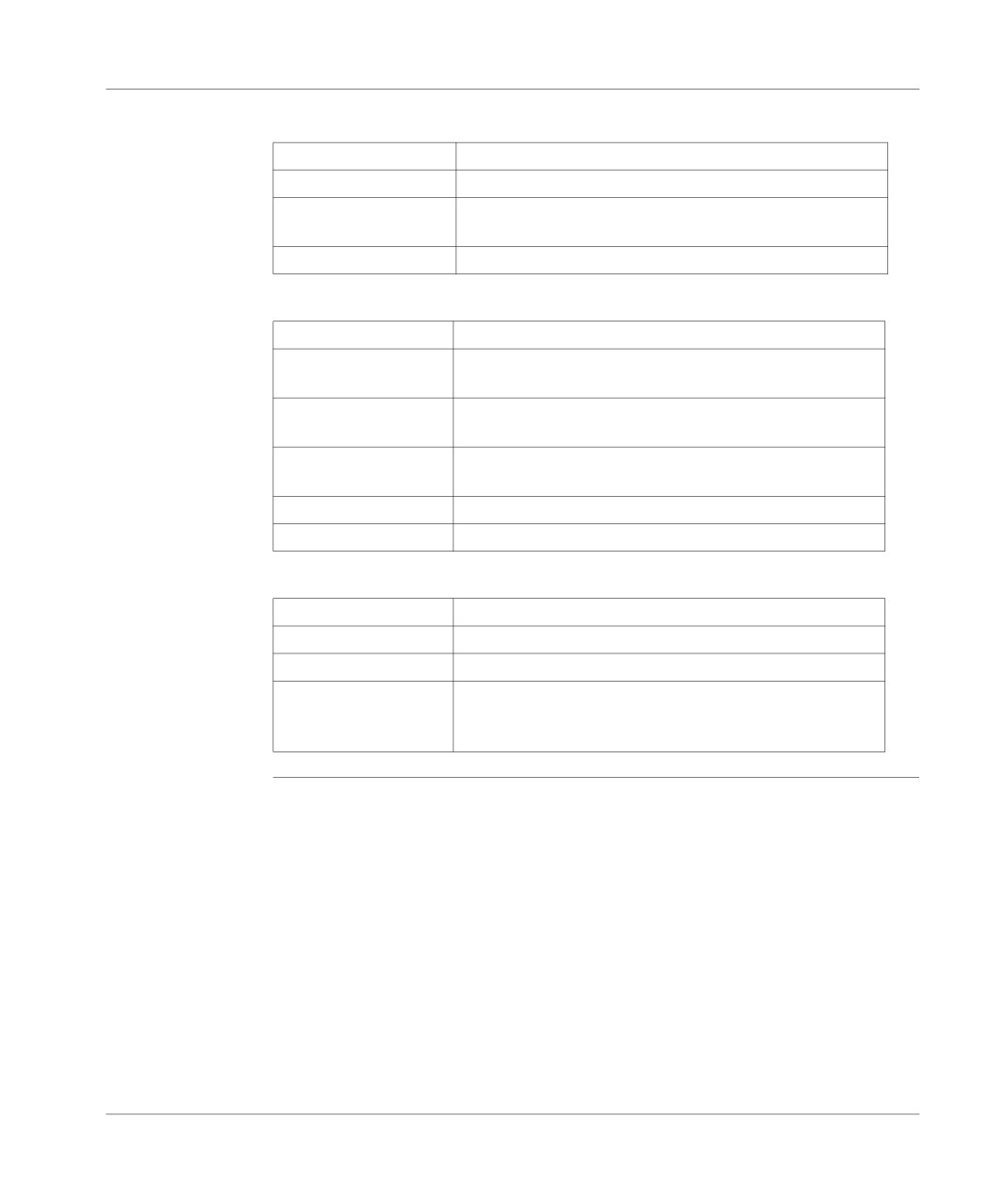
PL7 directories
Directories created on C:
and files
C:\PL7USER\
directory containing client and demonstration applications,
C:\PL7TEMP\
directory used as temporary space,
C:\CONGIG.SYS
modified file incorporating the UNITELWAY and FIPWAY
drivers
C:\CONFIG.001
Old configuration file
Directories created on a path defined by the user (e.g.: D:\PROGRAMS\
\OFLIB32\
directory containing the functions
\PL7Micro33\
directory containing the module descriptions and executables
for PL7 Micro
\PL7Junior33\
directory containing the module descriptions and executables
for PL7 Junior
\PL7Pro33\
directory containing the module descriptions and executables
for PL7 Pro
\PL7SYS\
directory containing shared PL7 files
\XWAYDRV\
directory containing COM drivers
Directories created in C:\WINDOWS\
\PL7SYS\
directory containing history
\PL7SYS\HISTO.REF
file containing installation history
\PL7SYS.INI
initialization file
\START MENU\PRO-
directory containing the startup icons
GRAMS\MODICON
TELEMECANIQUE
24
Setting up
Execution
Carry out the following steps from the Start menu:
Step
Action
1
Select Programs from theStart menu.
2
Select the Modicon Telemecanique program group.
3
Select the software icon.
Uninstalling the
Carry out the following steps from the Start menu:
software
Step
Action
1
Go to Settings\Control Panel\Add-Remove programs.
2
Select PL7***V4.*.
3
Select Add-Remove.
4
Select the elements to be uninstalled (core and / shared components)
5
Select OK.
6
Confirm with YES.
7
At the information screen confirm the uninstall by selecting OK.
25
Presentation of PL7 functions
2
Presentation
What’s in this
This chapter describes very generally the various components of the software prod-
chapter
uct.
What’s in this
This Chapter contains the following Maps:
Chapter?
Topic
Page
Configuration editor
28
Variables editor
29
Editing in ladder language
30
Instruction list language editing
31
Structured text language editor.
32
Grafcet language editor
33
Animation tables
34
Debugging
35
Diagnostics
37
Operating screens
39
Structure of the documentation file
40
General software ergonomics
41
27
Presentation
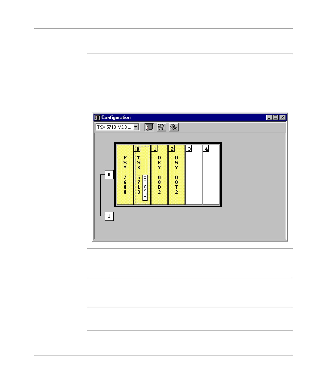
Configuration editor
Hardware
The configuration editor is used intuitively and graphically to declare and configure
configuration
the various constituent parts of the PL7.
l rack,
l supply,
l processor,
l application specific modules.
Editor:
Software
The configuration editor also ensures the software parametrizing of the application
configuration
by informing on the number of function blocks, registers and the size of the global
variable fields.
Configuring
If the Grafcet programming language has been used, the configuration editor is used
Grafcet objects
to define the Grafcet objects (steps, macro steps,….) and the execution parameters
(number of steps and active transitions).
Note
In on-line mode the configuration editor also provides the debugging, adjustment
and diagnostic functions.
28
Presentation
Variables editor
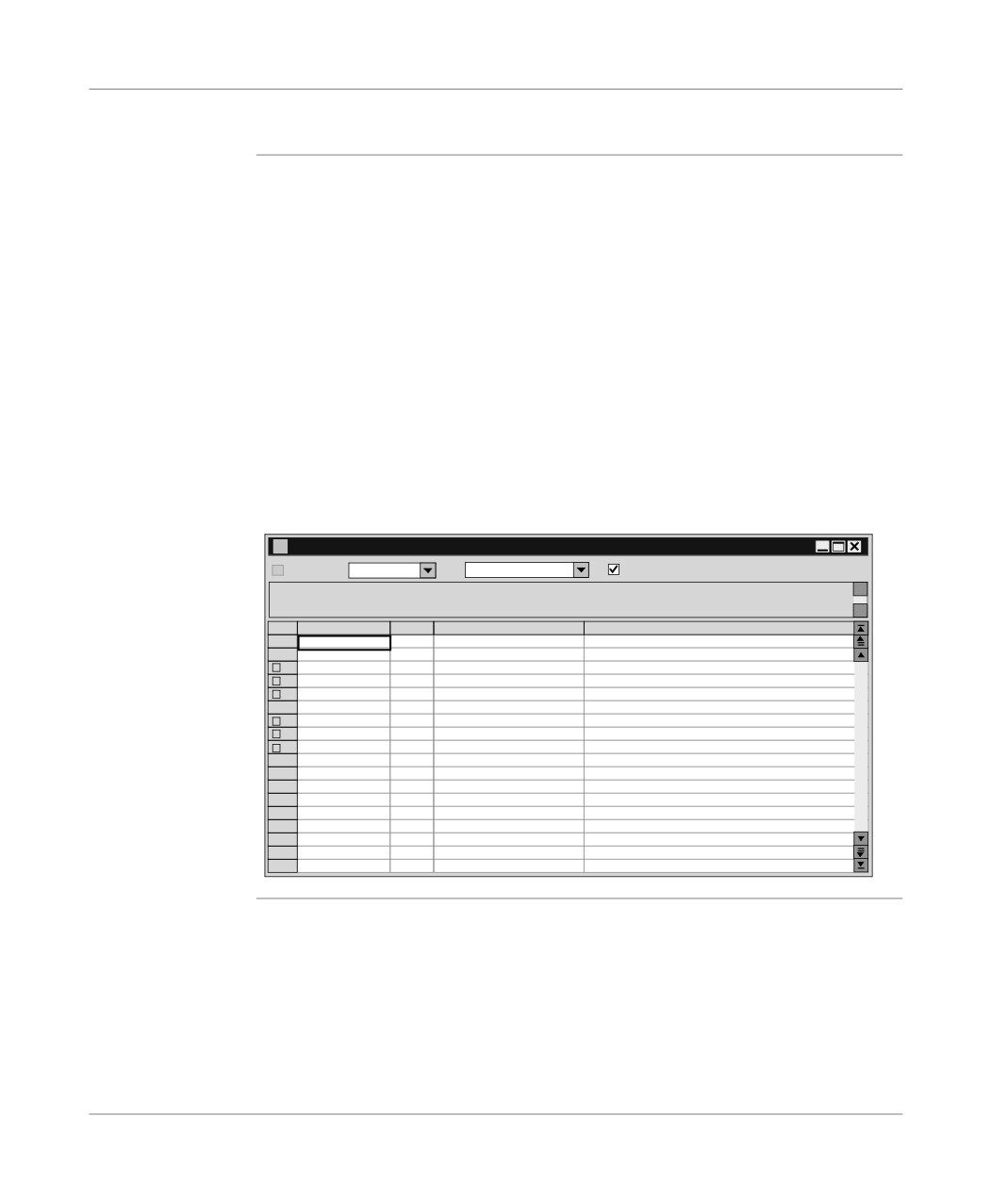
Presentation
The variables editor is used:
l to symbolize the various application objects,
l to parametrize the predefined function blocks,
l to enter the constant values and choose the display base,
l to parametrize the DFB user function blocks.
Access to variables is gained by:
l classifying by family and type,
l sorting functions (symbols or addresses),
l being able to pre-symbolize objects in certain applications,
l being able to launch a search with a joker on the symbol or comment,
l being able to filter the I/Os,
l being able to Copy/Paste by variables block,
l being able to remove pre-symbolization,
l displaying the variables used in the program in bold.
Editor:
Variables
Parameters
I/O
Addr
1: TSX DEY 16D2
Input zone
%CH1.MOD
Address
Type
Symbol
Comment
%CH1.MOD
CH
%I1.MOD.ERR EBOOL
+
%MW1.MOD
WORD
+
%MW1.MOD.1
WORD
+
%MW1.MOD.2
WORD
P
%CH1.0
CH
+
%KW 1.0
WORD
+
%KW 1.0.1
WORD
+
%KW 1.0.2
WORD
%I1.0
EBOOL PRESENCE_PIECE
detects a part in front of cylinder v 1
%I1.1
EBOOL
CAPTEUR_V1_ENTREE
sensor for return position of cylinder v 1
%I1.2
EBOOL
CAPTEUR_V1_SORTIE
sensor for out position of cylinder v 1
%I1.3
EBOOL
CAPTEUR_V2_ENTREE
sensor for return position of cylinder v 2
%I1.4
EBOOL
CAPTEUR_V2_SORTIE
sensor for out position of cylinder v 2
%I1.5
EBOOL INIT
starts system
%I1.6
EBOOL
ARRET
stops automatic cycle
%I1.7
EBOOL
%I1.0.ERR
BOOL
29
Presentation
Editing in ladder language
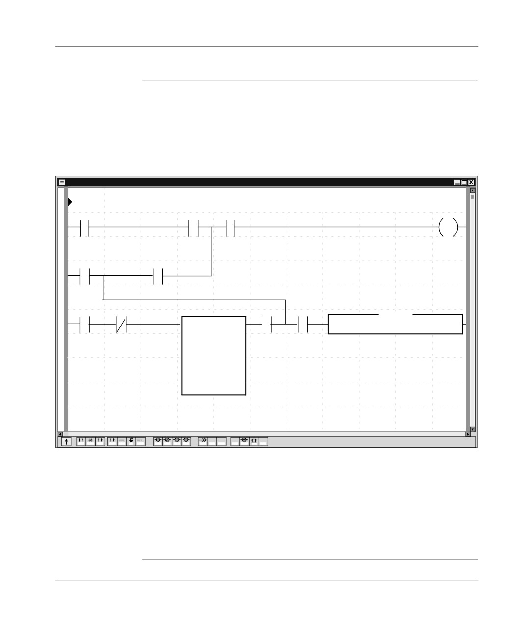
At a Glance
The Ladder editor offers a number of tools to help build a ladder in a user-friendly
way:
l a graphics palette,
l the language objects can be entered at random and displayed in the form of ad-
dresses, symbols or both at the same time,
l a collapsed view.
Editor:
LD : MAST - test
%I1.0
%M12
%I1.7
%Q2.
%TM4.Q
%M17
%I1.5
%M27
%TM0
%MW0:X5
%M25
OPERATE
%MVV15:=%MVV13*500
IN
TM
Q
MODE TON
TB: 1 s
TM.P: 10
MODIF: Y
P
N
S
R
OPER
COHPH
COHP
V
F (...)
F2
F3
F4
F5
F6
F7
F8
F9
F10
F11
F12
1.F2
1.F3
1.F4
1.F5
1S.F6
1F7
1.F8
The editor is used to immediately call up assisted entry functions:
l to access function libraries,
l to enter variables in the form of symbols or addresses.
When displayed, the ladders are shown in contracted form. It is thus possible to view
several ladders in the same window and to access them using the scroll bar or their
label.
A subroutine can be accessed directly from the call program.
30
Presentation
Instruction list language editing
Introduction
The Listeditor is used to input language instructions and operands via the keyboard,
they are formatted automatically.
The operands can be input and viewed either as addresses or symbols.
To make program reading easier, key words of the language and comments are dis-
played in color.
Instruction list editor.
IL: MAST - SR0
!
( * Verification of part in drying position * )
LD
%I1.0
AND
%I1.1
ST
%Q2.2
!
( * Start motor * )
LDN
%I1.0
ANDN
%I1.4
AND
%I1.3
ST
%Q2.0
The Instruction list language editor offers input help options :
l for function block instructions ((%TMi, %Ci,...),
l for functions, via the functions library.
31
Presentation
Structured text language editor.
Introduction
The editor is used to input program lines via the keyboard, using alphanumeric char-
acters.
The operands can be input and viewed either as addresses or symbols.
The editor provides a help option for function input via the functions library.
To make program reading easier, key words of the language and comments are dis-
played in color.
Structured text editor
ST : MAST - SR1
!
(*Search for the first not null element in a 32 word table
Determination of its value ( %MW10), and its rank (%MW11)
This search is carried out if %M0 is set to 1
%M1 is set to 1 if a not null element exists, if not it is set to 0*)
IF %M0 THEN
FOR %MW99: =0 TO31 DO
IF %MW100 [ %MW99 ] < >0 THEN
%MW10: = %MW100 [ %MW99 ];
%MW11: = %MW99;
%M1: =TRUE;
EXIT;
(*Exit FOR loop*)
ELSE
%M1: =FALSE;
END_IF;
END_FOR;
ELSE
%M1: FALSE;
END_IF;
32
Presentation
Grafcet language editor
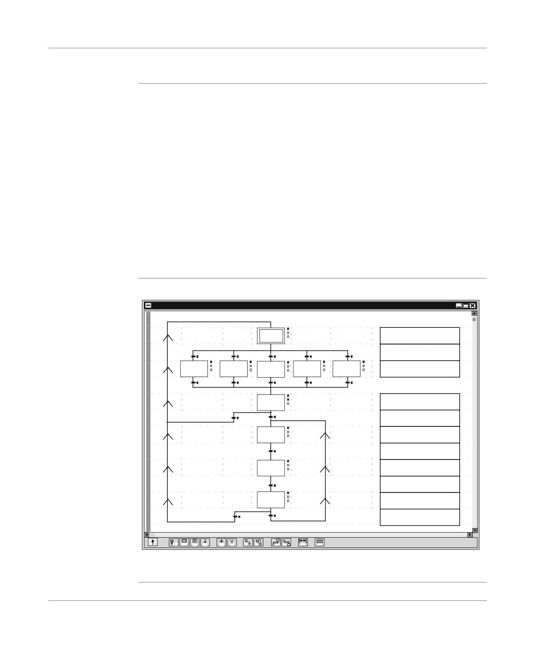
Presentation
The editor has a number of tools which are used to enter the chart in a user-friendly
manner:
l a range of graphic objects,
l access to the actions or receptivity programs,
l automatic numbering of steps,
l a display of each Grafcet page with step and transition lines,
l simplified entering of remarks,
l a reduced view.
The graph is constructed by selecting the desired object from the graphics palette
and putting it into the Grafcet page.
The graphics (fine lines) appear which ensures that the programmed graphic objects
are displayed immediately.
Illustration
Grafcet editor
GRAFCET: MAST - Chart
(*Display the Recipe
0
on the Display*)
(*Recipe Number*)
(*Copy the
1
2
3
4
5
Recipe data*)
(*Select the Recipe
1
with the Display key*)
(*Start the cut/
New Recipe*)
(*Advance the high-speed
1
bar*)
(*Deceleration threshhold
reached*)
(*Advance the low-speed
1
bar*)
(*Length of cut
reached*)
1
(*Cut off a section*)
(*New section/
Cut completed*)
F2
F3
F4
F5
F6
F7
F8
F9
F10
F11
F12
1F2
The Grafcet editor behaves like an editing field by shifting onto a complete module
of 8 Grafcet pages.
33
Presentation
Animation tables
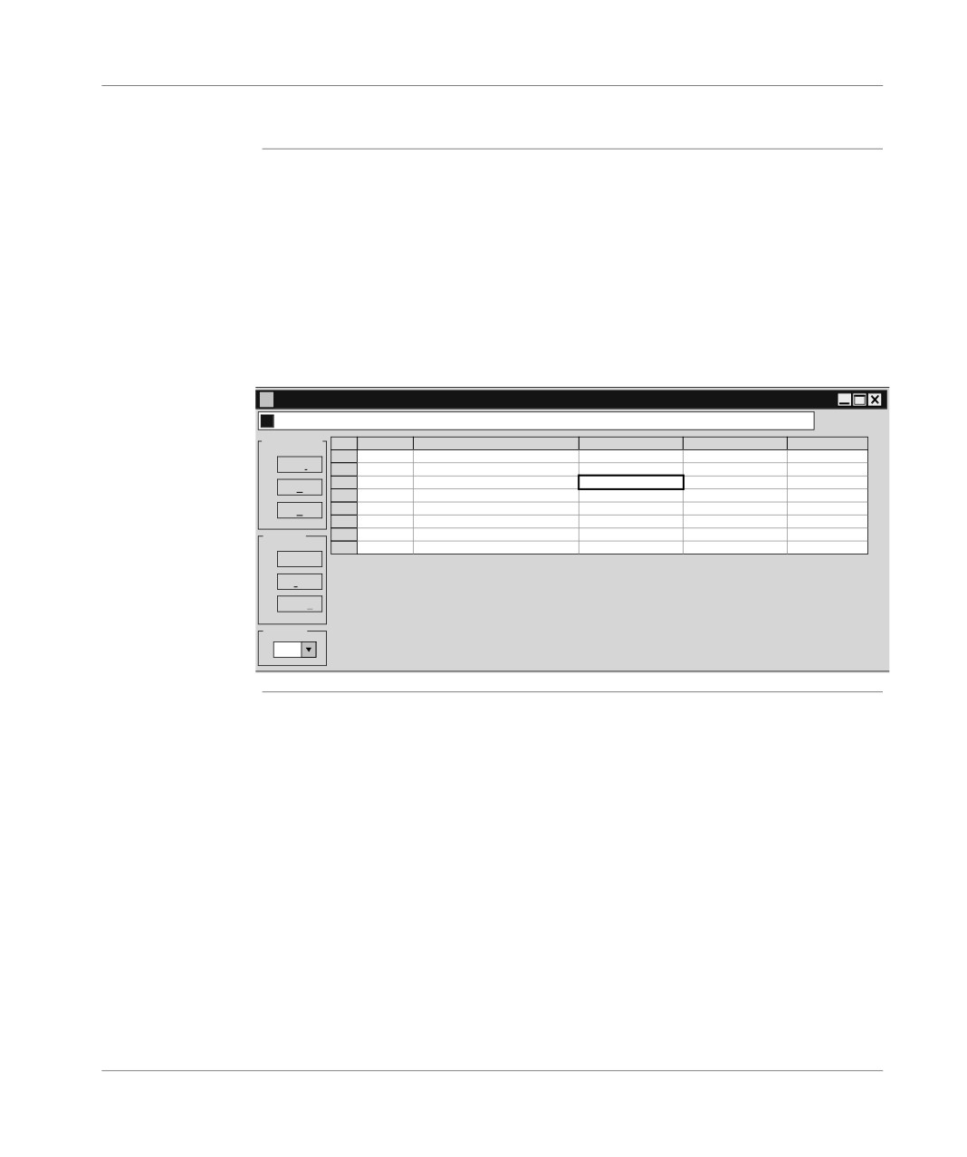
At a Glance
Animation tables can be created by entering them or automatically initializing them
from the rungs, selected sequences, or animated objects in the runtime screens.
The variables can then be:
l modified,
l forced to 0 or to 1 for the bit objects.
For each numerical variable it is possible to select the display base (decimal, binary,
hexadecimal, floating, ASCII message).
Animation table:
Table: TABLE_TEST (Animated)*
0
7/8
Modification
Address
Symbol\Name
Current value
Nature
Type
%Q3.0
TEMOIN_DEMARRAGE
1
F3
Modify
%Q3.1
TEMOIN_TEMPO
0
F7
0
%I4.0
DEMARRAGE
0
%I4.1
ARRET
0
F8
1
%M0
MEMO_RETARD_ALLUMAGE
0
%M1
MEMO_FONCTIONNEME
1
Forcing
%TM0.V
RETARD_ALLUMAGE-V
8
F4 Force 0
F5 Force 1
F6 Unforce
Display
Dec.
34
Presentation
Debugging
Debugging tools The PL7 software offers a complete range of tools for debugging applications.
A range of tools is used to access the main functions directly:
l setting the break point,
l running the program from step to step,
l independent running of the MAST master task and the FAST rapid task.
Debugging bar
Debug
Ap
Surv
Mast
Fast
Evt
GO
c
c
c
F
cR7
RUN a
RUN a
RUN a
CU debugging
This CU debugging screen has the following functions:
screen
l information on the application status,
l controlling the running of the program,
l access to the diagnostic module specific programs,
l access to updating and display of the real time clock.
Diagnostic tool:
TSX 57302 [RACK 0 POSITION 0]
Debug
Designation: PROCESSOR TSX P 57302
RUN
IO
ERR
DIAG...
Information
Processor present:
TSX 57302
Processor version:
3.0(35)
Network address:
SYS
Number of forced bits:
1
Task
Period
Minimum
Current
Maximum
Cycle time
WatchOperating
State Cmd Activate
Error Init
Reset
Set
Duration
Duration
Duration
FIPIO
dog
Mode
task
duration
Fault
Network
MAST
CYCLIC
2
6
12
Not pres
250
RUN a Stop Deactivate Fault Init Reset
FAST
5
0
1
2
Not pres
100
RUN a Stop Deactivate Fault Init Reset
Operating Mode
Events
Warm restart
Fault
Reset fault bit
Output fallback
State:
RUN active
Outputs in fallback mode
Cold start
Number of events:
0
Last stop
Timestamp
Cause
Change to Stop
Tuesday
Tuesday
24/02/1998
OK
Upd
Date:
24/02/1998
Time:
10:47:55
10:49:13
Cancel
35
Presentation
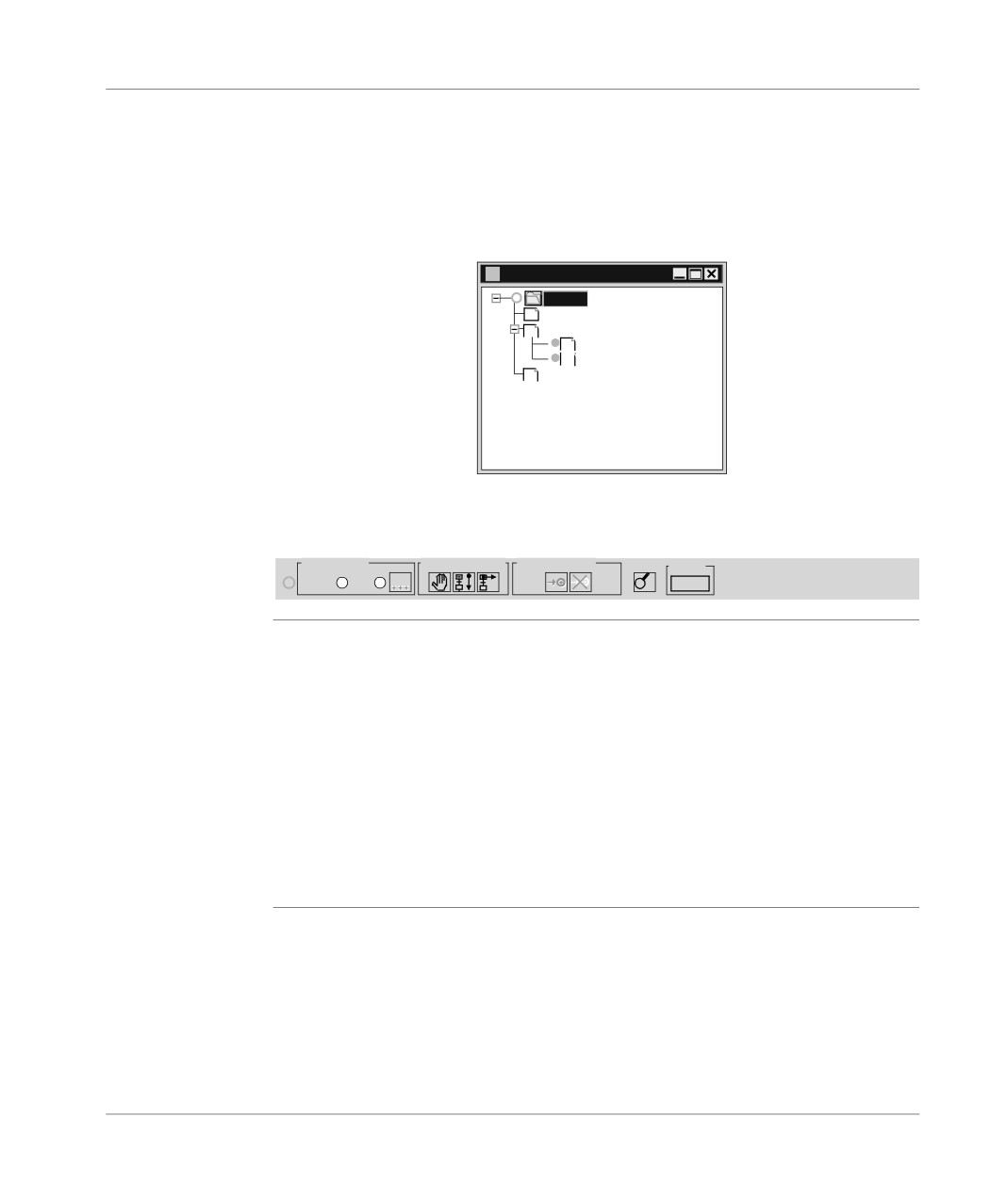
Grafcet
This Grafcet debugging screen is used to give a hierarchical display of the graph
debugging
with overlays of the CHART module and the macro steps.
screen
This view is animated on line. The animation is represented by the absence and
presence of flags.
Debugging browser
Grafcet Debug Browser
operate
Prl
G7
Chart
G7
Macro0
G7
Macro1
LD
Post
The debugging bar is used to display the status of the graph, to modify the status of
the graph, to inform on the status of the master task.
Debugging bar
Chart status
Actions on chart Prepositioning
Mast
Frozen
Error
PRG
RUN a
Debugging
Organizing a function module, distributing the sections, events and Grafcet modules
function
to the various modules has no effect on the running of the program. This is carried
modules
out according to the order shown in the structure view.
To debug a function module, the user has basic debugging functions and additional
functions used for incremental debugging of the application, function module by
function module.
These functions are:
l deactivating all sections attached to a function module,
l activating all sections attached to a function module,
l cancelling the forcing of all sections attached to a function module.
36
Presentation
Diagnostics
Diagnostics tool
The software provides various diagnostics tools. To access the tools you need to be
in online mode.
These tools are:
l diagnostics for the PLC’s last operational stop,
l module/channel diagnostics,
l program diagnostics,
l system diagnostics (See "Diagnostics functions installation manual",)
l Diagnostics DFBs (See "Diagnostics functions installation manual")
Diagnostics
Can be used with PL7 PRO. The diagnostics DFBs are composed of:
DFBs
l Application diagnostics DFBs, which are used to set up process monitoring via
the application program:
l PL7 equation monitoring,
l monitoring the reaction time of the process to a command,
l monitoring safety conditions,
l monitoring inputs, outputs and the ASI bus.
l Working part control and diagnostics DFBs which are used to control and monitor
elements of the working part (EPOs):
l monitoring sensor information,
l monitoring actuator control requests,
l monitoring the duration of a movement,
l storing minimum and maximum movement durations,
l learning the duration times of a movement,
l controlling an actuator.
The library breaks down into the following DFBs:
EV_DIA
Monitoring the status of 2 bits without taking a time factor into account.
MV_DIA
Monitoring the status of two bits without taking a time factor into account, with
the option of monitoring a movement’s changes (change of bit status within a
given time period).
NEPO_DIA
Monitoring, checking and diagnostics for a working part element.
TEPO_DIA
IO_DIA
Diagnostics for all the I/O modules.
ASI_DIA
Diagnostics for an Asi input/output module.
ALRM_DIA
Interface with a diagnostics buffer (storage of errors).
37
Presentation
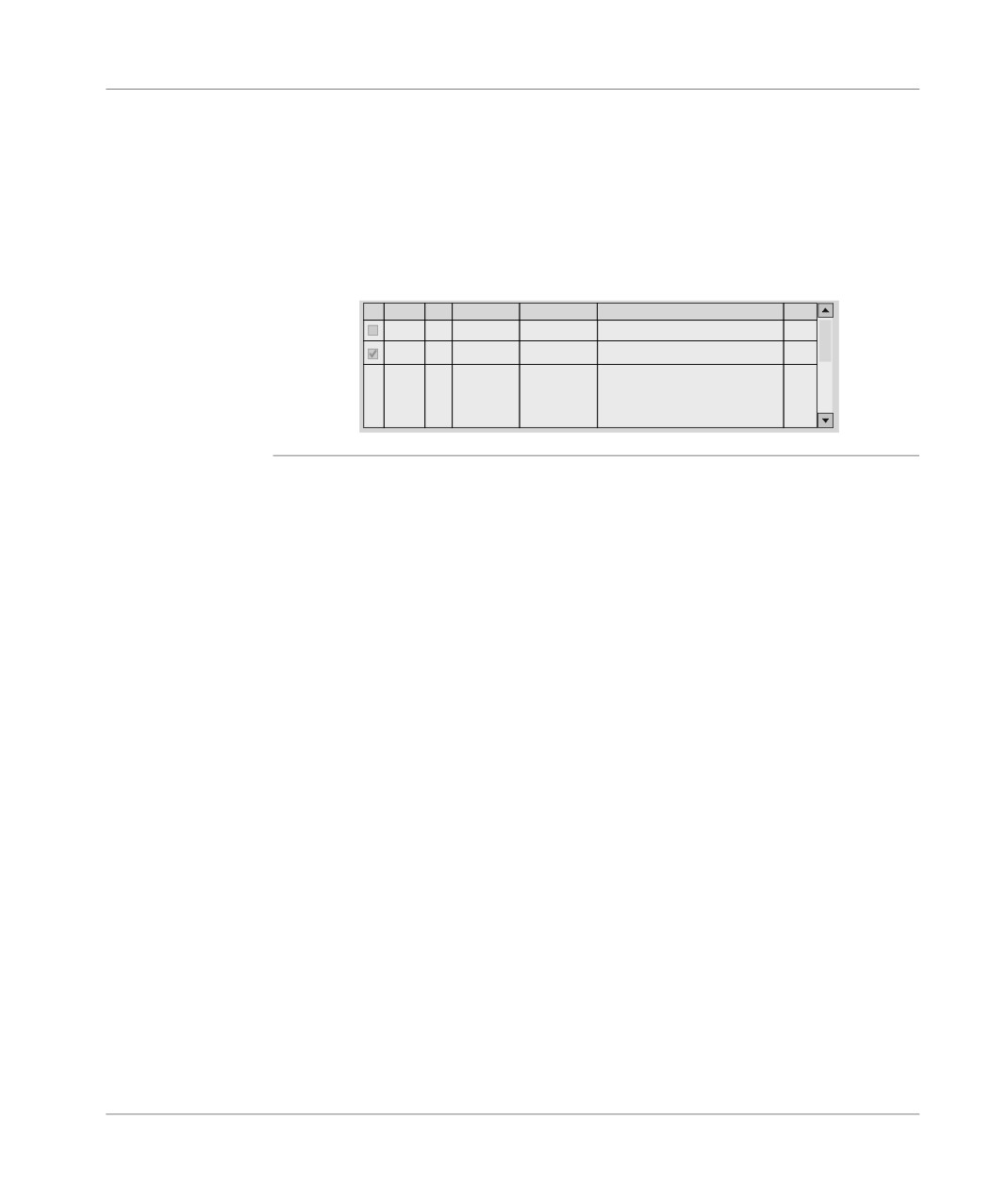
Error message:
Each DFB has its own standard error message, which may be customized according
to the type of DFB.
Error messages are displayed on a Viewer integrated into PL7 Pro. A Diagnostics
Viewer is also available with the CCX17 V2.5
Viewer:
Ack Error Zone Appearance Disappearance Error Message
Status
ALARM
0
10/03/1998...
10/03/1998...
Silo empty or weighing ho
0.2
EV_DIA
0
11/03/1998...
11/03/1998...
DEF_1_DEFAUTS PLC 1 HO ISLAND...
0.2
38
Presentation
Operating screens
Presentation
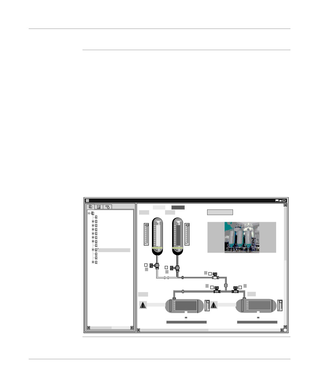
The operating screens editor is a tool integrated into the PRO PL7 program from ver-
sion V3.0 onwards.
It is used to make running an automated process easier.
From the screen tab you can:
l create operating screens, screen families,
l manage importing and exporting screens and screen families,
l manage the link between the screen number and the screen browser object,
l list all the variables used in a screen,
l parametrize the screen (size, elevator, full screen, mouse position….),
l copy/paste one or more objects,
l display the errors found by the diagnostic DFBs in the program.
From the message tab you can:
l Create the messages used in the screens.
From the screen tab you can:
l Create a library of graphics objects.
Operating screen:
Run-time screen IE2.14: Product mix
a
S o l v e n t
R e a g e n t
Screen
VAL
L I T E R
VAL
LI T E R
Contents
1 - Contents
V o l u m e
4 - Program debug
2 - Chemical process
1
1
111 - Clock
3- VOIT LINE DIAGRAM
34 - PRO CUT DIAGRA
27 - DEF_1_DEFAUTS
0
0
24 - SYNZ1_SYNOPTI
112 - Product mix
5 - Screen 1 blank for
5 - Screen 2 blank for
E v o l u t i o n at v e s s e l l e v e l
7 - Valve management
0
0
0
0
0
VAL
L I T E R S
VAL L I T E R S
1
1
A N O M A L Y
A N O M A L Y
0
0
39
Presentation
Structure of the documentation file
At a Glance
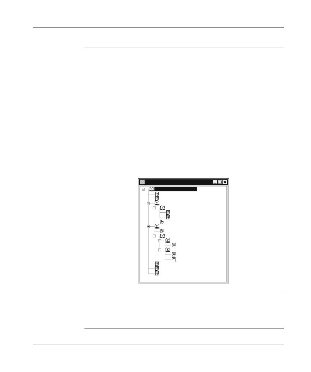
The documentation editor is linked to the Documentation browser which shows the
documentation file structure in tree diagram format.
The documentation editor is used to define:
l a title page containing the name of the project and the designer,
l general information pages,
l a cartridge.
The documentation editor automatically generates:
l the contents table,
l the application documentation file (hardware/software configurations and pro-
gram),
l the list of variables sorted by address or by symbol.
The documentation editor is also used:
l to print all or part of the application documentation file,
l to display documentation file pages before printing.
Documentation browser:
Documentation
Station Documentation File
Title page
Contents
Configuration
Hardware configuration
Rack configuration
Module parameters
Software configuration
Program
Application structure
MAST Task
Sections
normal_cycle
Sr
Sr0
Sr1
Cross references
Variables
Footer
For functional
When the documentation tool is launched, it detects whether there is at least one
modules
functional module referencing either program modules which are not empty (Sec-
tion, Evt, Grafcet modules, Srs), or animation tables.
If this is the case, an additional node "Function view" is added to the directory tree.
40
Presentation
General software ergonomics
General points
The PL7 software uses all the standard working tools for Windows:
l mouse or keyboard,
l drop-down menus,
l browsers,
l tool bars and palettes with icons,
l several tools in parallel,
l on-line help and tool tips.
Standard
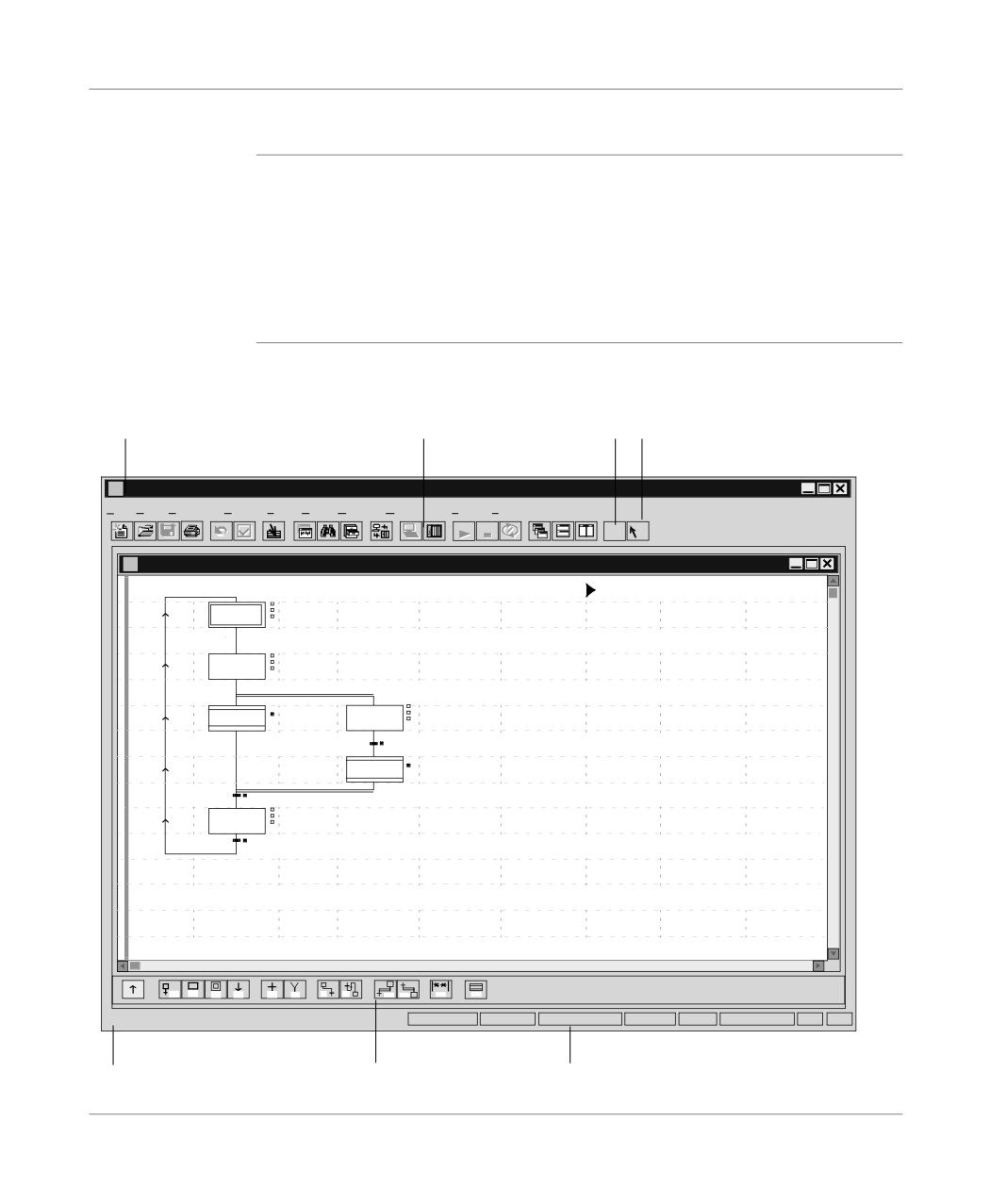
PL7 software uses Windows ergonomics and looks like this:
elements
Example of a window:
1
2
3
4
PL7 PRO: IE54VT
File Edit
Services View Tools PLC Debug Options Window
?
RUN
STOP
?
?
GRAFCET: MAST - run - Chart
0
1
M0
2
M1
5
F2
F3
F4
F5
F6
F7
F8
F9
F10
F11
F12
1F2
Ready
OFFLINE
U:SYS
GR7 NOK
OVR
5
6
7
41
Presentation
This table describes the different zones:
Number
Description
1
Menu bar, which is used to access all the software functions.
2
Tool bar for rapid access to all basic functions using the mouse.
3
On-line help on how to use the software.
4
Context sensitive help for the software.
5
Comments zone.
6
Palette of graphics elements.
7
Work context.
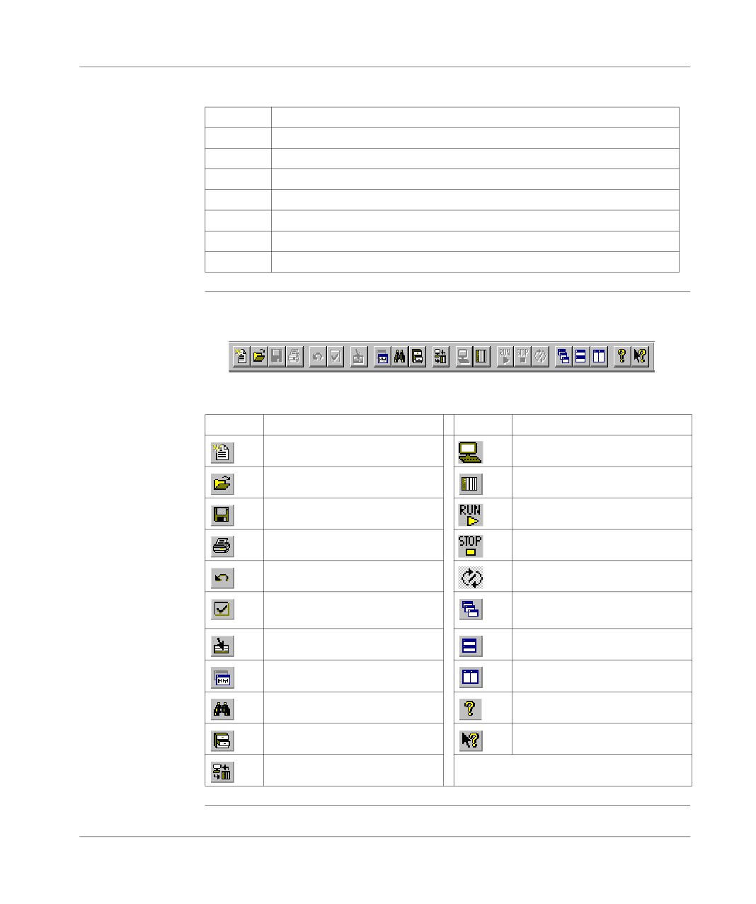
Tool bar
The tool bar provides a rapid means of access to the standard software functions:
This table shows what each element of the tool bar is for:
Element
Function
Element
Function
New application
Offline mode
Open an application
Online mode
Save the application
Switch PLC to RUN mode
Print all or part of the application
Switch the PLC to STOP mode
Undo
Start / Stop animation
Confirm modifications
Arrange the windows in a cas-
cade
Go to
Tile Horizontally
Application browser
Tile Vertically
Cross references
Help
Function library
What’s This?
PLC transfer<-> terminal
42
Presentation
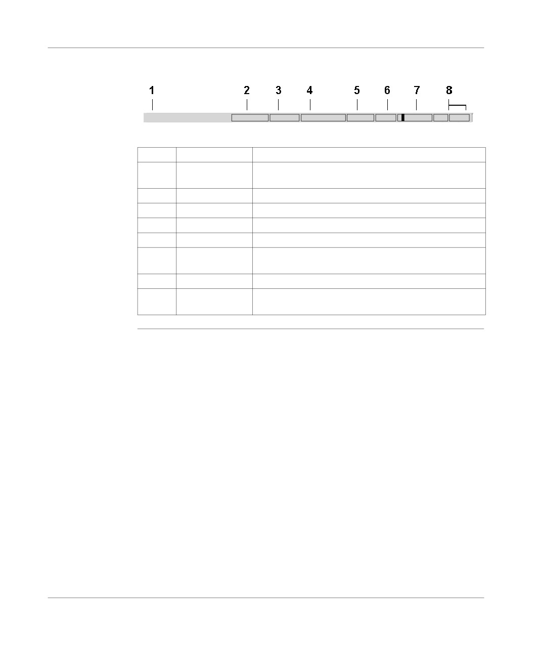
Status bar
The PL7 status bar looks like this:
Ready
ONLINE
STOP
U:SYS
GR7 OK MODIF
OVR SHIFT
This table describes the different zones that make up the status bar:
Number
Zone
Function
1
Mini on-line help
Provides help linked to the menu commands or tool bar icons
when these are selected.
2
Operating mode
Shows the current operating mode (offline, online).
3
PLC status
Shows the PLC status (Run, Stop, faulty,etc.).
4
Network address
Provides details of the PLC’s network address.
5
Grafcet mode
Shows whether Grafcet mode is used in the application.
6
Modification in
Shows that the current application is not backed up or is dif-
progress
ferent from the back up.
7
Animation flag
Symbol for online mode.
8
Keyboard func-
Shows the status of the Insert and Caps functions of the key-
tions
board.
43
//////////////////////////////////////////