TSX Micro PLCs TSX 3705/3708/3710/3720. Implementation Manual (Volume 1) - page 7
Counting functions on (500Hz) discrete inputs
Up/down counting
Introduction
Several possibilities can be used on each channel.
First possibility
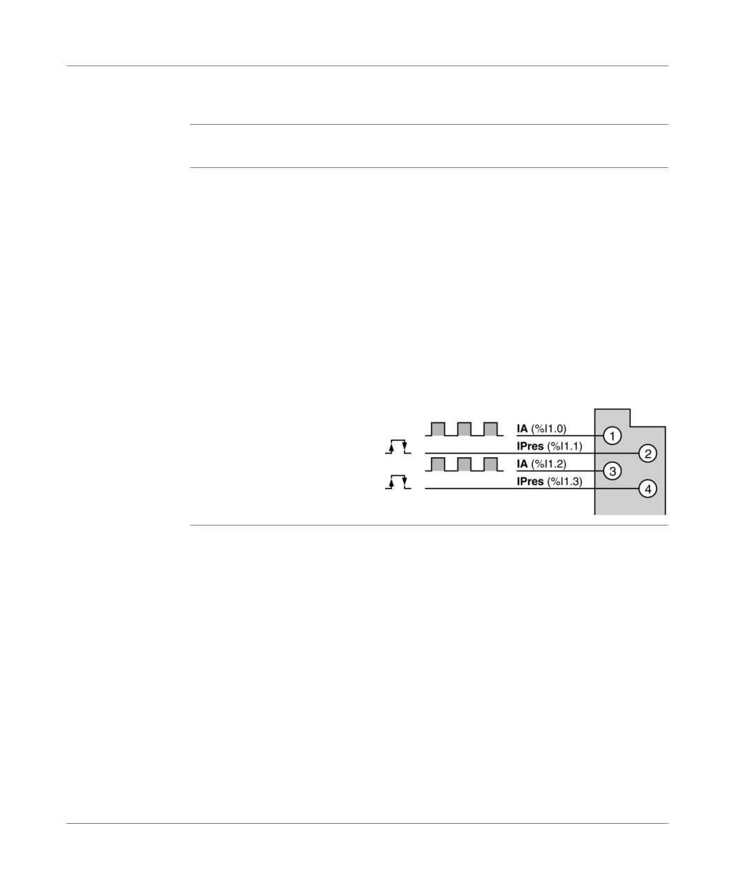
When using a single physical up/down counting input, the direction (up or down
counting) is defined by the application by setting a bit object to 0 or 1.
The up/down counting pulses are received on the IA input: %I1.0 for channel 0 and
%I1.2 for channel 1.
Setting the preset value can be carried out according to one of the methods
described below:
when changing the status of the input IPres: %I1.1 for channel 0 and %I1.3 for
channel 1 (rising or falling edge, choice made in configuration) and when this is
validated in the software,
via software.
Illustration:
Module in position 1
Channel 0 input counting up/dow
Channel 0 preset input
Channel 1 input counting up/down
Channel 1 preset input
TSX DM 37 xxE
243
Counting functions on (500Hz) discrete inputs
Second
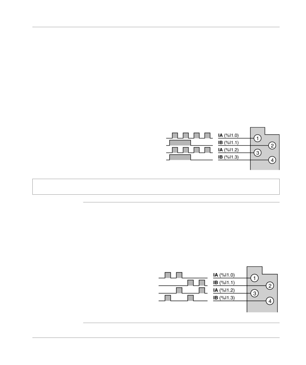
When using a single physical up/down counting input, the direction (up or down
possibility
counting) is defined by setting the second input to 0 or 1.
The up/down counting pulses are received on the IA input:
%I1.0 for channel 0,
%I1.2 for channel 1.
The input IB is used to define the counting direction:
%I1.1 definition of channel 0 counting direction: (status 1: count up, status 0:
count down),
%I1.3 definition of channel 1 counting direction: (status 1: count up, status 0:
count down).
In this case, the preset value is set by the software only.
Illustration:
Module in position 1
Channel 0 input counting up/down
upcount downcount
Channel 0 input count direction
Channel 1 input counting up/down
upcount downcount
Channel 1 input count direction
Note: The pulses on the IA input are taken into account for up or down counting if the IB input has been
positioned in status 1 (count up) or in status 0 (count down) for at least 100 micro seconds.
Third possibility
Using two physical up/down counting inputs for each channel:
Channel 0:
the up counting pulses are received on the IA input (%I1.0),
the down counting pulses are received on the IB input (%I1.1),
Channel 1:
the up counting pulses are received on the IA input (%I1.2),
the down counting pulses are received on the IB input (%I1.3),
Illustration:
Module in position 1
Channel 0 counting input
Channel 0 down counting input
Channel 1 counting input
Channel 1 down counting input
Note: in this case, the preset value is set by the software only.
244
TSX DM 37 xxE
Counting functions on (500Hz) discrete inputs
Fourth
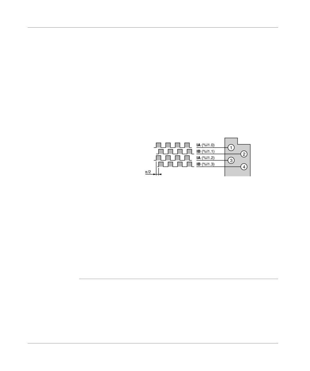
Using two physical up/down counting inputs with Pi/2 shifted signals (incremental
possibility
encoder signals):
Channel 0:
signal A on input IA (%I1.0),
signal B on input IB (%I1.1),
Channel 1:
signal A on input IA (%I1.2),
signal B on input IB (%I1.3),
In this case, the preset value is set by the software only, and the immunity of these
four inputs is automatically fixed to the minimum value of 0.1ms if they are 24V DC
inputs.
Illustration:
Module in position 1
Input A channel 0
Input B channel 0
Input A channel 1
Input B channel 1
These functions can be used equally on the modules:
with a screw or HE10 connector terminal block,
with direct current inputs,
with alternating current inputs, in which case the up counting frequency will be
limited given the response time of this type of input.
If channel 1 is not used, the corresponding inputs can be configured into event, latch
state or normal discrete inputs. In this case, and if the inputs being used are supplied
by direct current, the immunity of these inputs will be defined for the inputs assigned
to up or down counting.
Channels 0 and 1 can be configured independently of one another with, for example,
one channel in up/down counting and the other in up or down counting.
TSX DM 37 xxE
245
Counting functions on (500Hz) discrete inputs
246
TSX DM 37 xxE

Up counting functions built in to
(10KHz) TSX 37 22 bases
27
At a Glance
Aim of this
This chapter deals with the up counting functions which are built in to the (10KHz)
chapter
TSX 37 22 bases.
What's in this
This Chapter contains the following Maps:
Chapter?
Topic
Page
Introduction
248
Up or down counting
249
Up/down counting on channels 11 and 12
251
Up/down counting only on channel 11 (first possibility)
252
Up/down counting only on channel 11 (first possibility)
254
Up/down counting only on channel 11 (third possibility)
255
Preset on reference point short cam
257
TSX DM 37 xxE
247
Up counting functions built in to (10KHz) TSX 37 22 bases
Introduction
General points
The count interfaces of the TSX 37 22 bases can be used to create 2 upcount
channels, 2 downcount channels or independent upcount/downcount channels
(channel 11 and channel 12 located in position 0).
Each count channel can receive 5 VCC/RS 422 or 24 VCC signals at a maximum
frequency of 10 kHz.
Preset inputs can only received 24 VCC signals.
248
TSX DM 37 xxE
Up counting functions built in to (10KHz) TSX 37 22 bases
Up or down counting
General points
The up or down counting pulses are received on the IA input.
Setting to 0 (up counting) or setting the preset value (down counting) can be carried
out according to one of the methods described below:
when the status of the input IPres11 is changed for channel 11 (rising or falling
edge, choice made in configuration) and when this is validated in the software,
when the status of the IPres12 is changed for channel 12 (rising or falling edge,
choice made in configuration) and when this is validated in the software,
automatically as soon as the preset value (up counting) or the value 0 (down
counting) has been reached, this choice being made in configuration,
via software.
Note: symbols used in PL7 screens
IPres if it is a down counting function,
IReset if it is an up counting function.
TSX DM 37 xxE
249
Up counting functions built in to (10KHz) TSX 37 22 bases
Principle
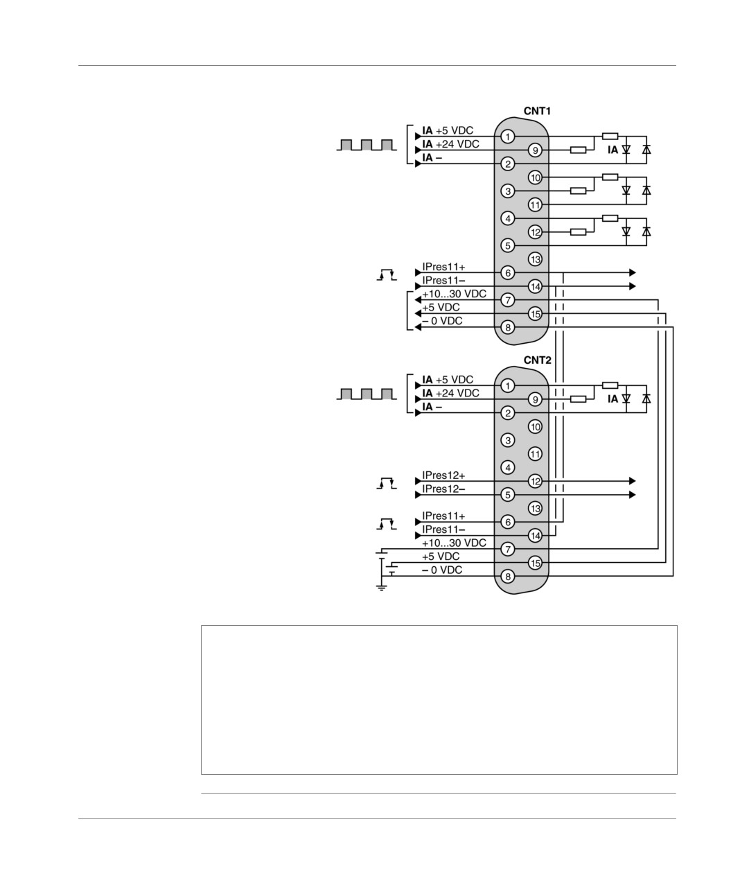
Illustration:
Diagram
Input
pulses towards 11
Reset input to 0
or select channel 11
Supply reserved exclusively for
the encoder supply (rollup of
external supply connected to the
CNT2 connector)
Input
pulses towards 12
Reset input to 0
or select channel 12
Reset input to 0
or select channel 11
External supply
10...30 VDC or 5 VDC
for encoder
Note:
Channels 11 and 12 can be configured independently of one another with, for
example, one channel in up counting and the other in down counting or up/down
counting,
The IPres 11 input and the external supply encoder are shared between the
connectors CNT1 and CNT2 in order to make wiring easier, particularly if an
encoder is used. In this case, the CNT1 connector is reserved exclusively for the
encoder connector, and the CNT2 connector is used for connecting the IPres 11
input and the external supply of the encoder.
250
TSX DM 37 xxE
Up counting functions built in to (10KHz) TSX 37 22 bases
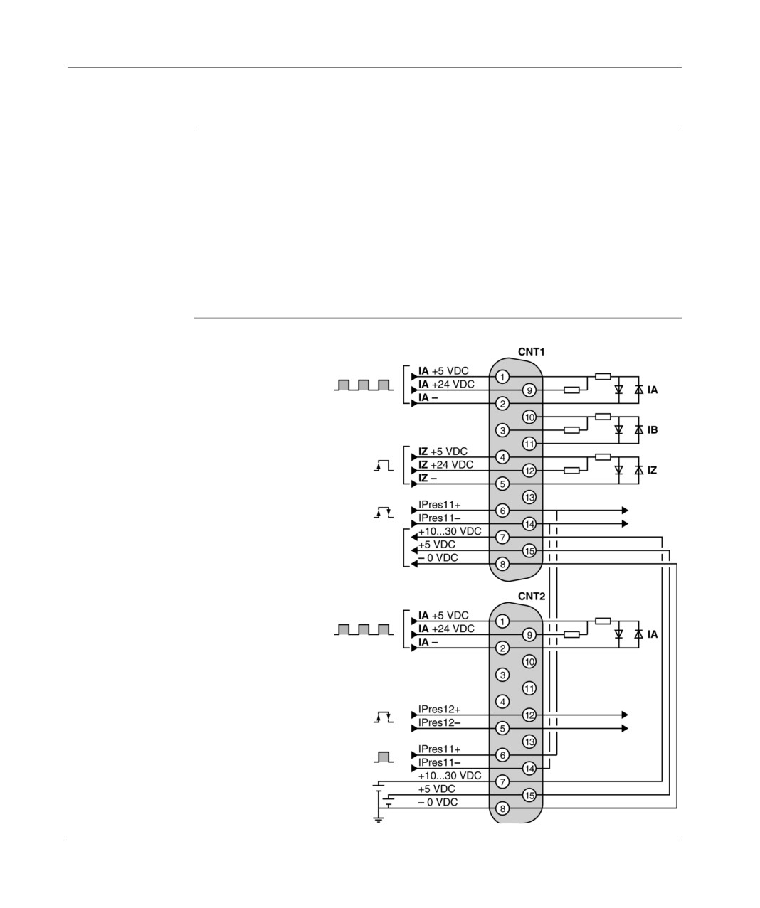
Up/down counting on channels 11 and 12
General points
When using a single physical up/down counting input, the direction (up or down
counting) is defined by the application program by setting a bit object to 0 or 1.
Up/down counting pulses are received on the IA input.
The preset value can be set:
either when changing the IPres input status..: IPres11 for channel 11 andIPres12
for channel 12 (rising or falling edge, choice made in configuration),
either on reference point short cam, on channel 11 only (see Preset on reference
point short cam, p. 257),
or by the software.
Principle
Illustration:
Diagram
Channel 11
Upcounting/
downcounting input
Channel 11 Top-turn input
Channel 11 preset input
Supply reserved exclusively
for the encoder supply (rollup of
external supply connected to the
CNT2 connector)
Channel 12
Upcounting/
downcounting input
Channel 12 preset input
Channel 11 preset input
External supply
10...30 VDC or 5 VDC for
encoder
TSX DM 37 xxE
251
Up counting functions built in to (10KHz) TSX 37 22 bases
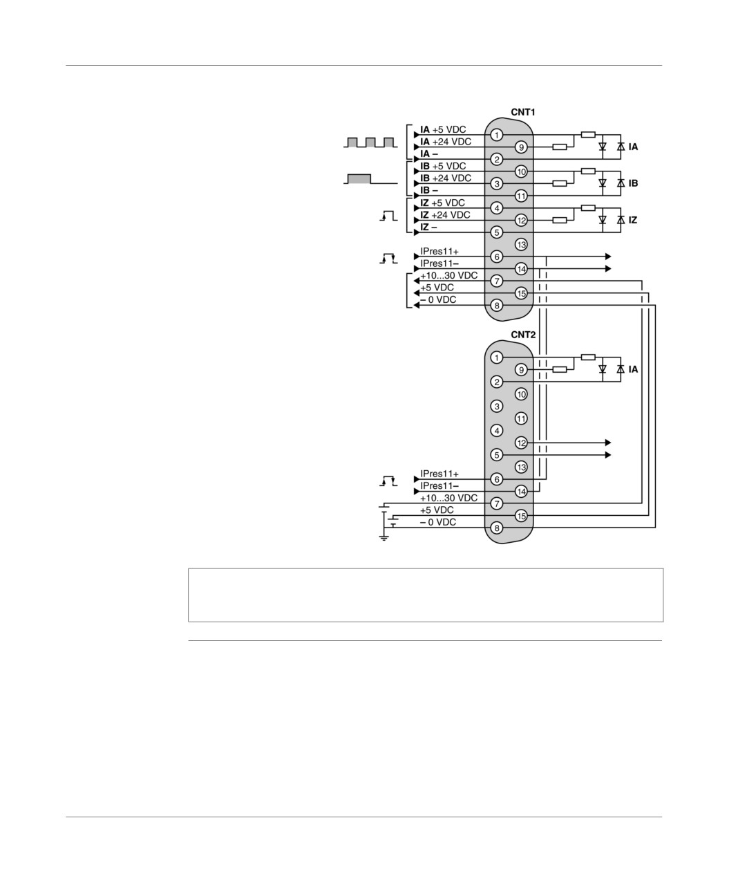
Up/down counting only on channel 11 (first possibility)
General points
When using a single physical up/down counting input, the direction (up or down
counting) is defined by setting the second input to 0 or 1.
the up/down counting pulses are received on the IA input,
the direction (up or down counting) is defined by positioning of the IB input to
status 1 or 0 (status 1: up count, status 0: down count).
The preset value can be set:
either when the status of the IPres11 input is changed (rising or falling edge,
choice made in configuration),
or on short cam reference point,
or by the software.
252
TSX DM 37 xxE
Up counting functions built in to (10KHz) TSX 37 22 bases
Principle
Illustration:
Diagram
Channel 11 Upcounting/
downcounting input
Input counting direction
downcoun
channel 11
upcount
Channel 11 Top-turn input
Channel 11 preset input
Supply reserved exclusively for the
encoder supply (rollup of external
supply connected to the CNT2
connector)
Channel 11 preset input
External supply
10...30 VDC or 5 VDC for
encoder
Note: In this case, channel 12 can be used:
either in up counting or in down counting,
or in up/down counting (see Principle Diagram, p. 251).
TSX DM 37 xxE
253
Up counting functions built in to (10KHz) TSX 37 22 bases
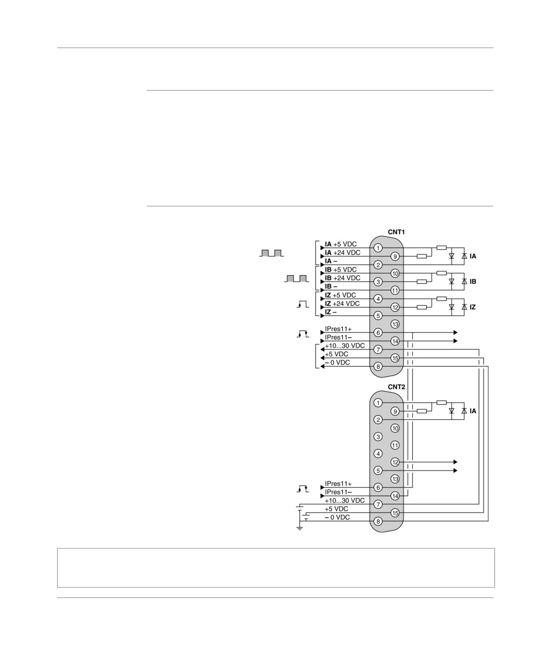
Up/down counting only on channel 11 (first possibility)
General points
Using two physical inputs, an upcount input and a downcount input.
the up counting pulses are received on the IA input,
the down counting pulses are received on the IB input.
The preset value can be set:
either when the status of the IPres11 input is changed (rising or falling edge,
choice made in configuration),
or on short cam reference point,
or by the software.
Principle
Illustration:
Diagram
Channel 11 counting input
Channel 11 down counting input
Channel 11 Top-turn input
Channel 11 preset input
Supply reserved exclusively
for the encoder supply (rollup of
external supply connected to the
CNT2 connector)
Channel 11 preset input
10…30 VDC external supply
for encoder
Note: In this case, channel 12 can be used:
either in up counting or in down counting,
or in up/down counting (according to the up/down counting principle diagram on channels 11 and 12).
254
TSX DM 37 xxE
Up counting functions built in to (10KHz) TSX 37 22 bases
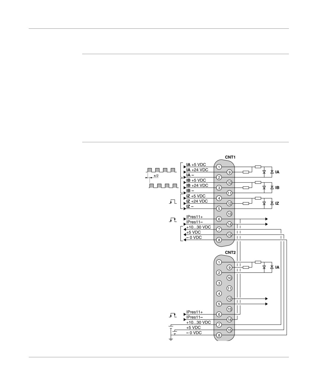
Up/down counting only on channel 11 (third possibility)
General points
Using two physical inputs with Pi/2 shifted signals (incremental encoder signals)
without hysteresis and multiplying by 1 or 2 according to the choice defined in the
configuration.
The up counting signals are received on the inputs:
IA for the A signals,
IA for the B signals.
The preset value can be set:
either when the input status is changed IPres11 (rising or falling edge, choice
carried out in configuration),
or on short cam reference point,
or by software.
Principle
Illustration:
Diagram
Channel 11 A signal input
Channel 11 B signal input
Channel 11 Top-turn input
Channel 11 preset input
Supply reserved exclusively for the
encoder supply (rollup of external
supply connected to the CNT2
connector)
Channel 11 preset input
External 10…30 VDC or
5 VDC supply for encoder
TSX DM 37 xxE
255
Up counting functions built in to (10KHz) TSX 37 22 bases
Note: In this case, channel 12 can be used:
either in up counting or in down counting,
or in up/down counting (according to the up/down counting principle diagram on channels 11 and 12).
256
TSX DM 37 xxE
Up counting functions built in to (10KHz) TSX 37 22 bases
Preset on reference point short cam
General
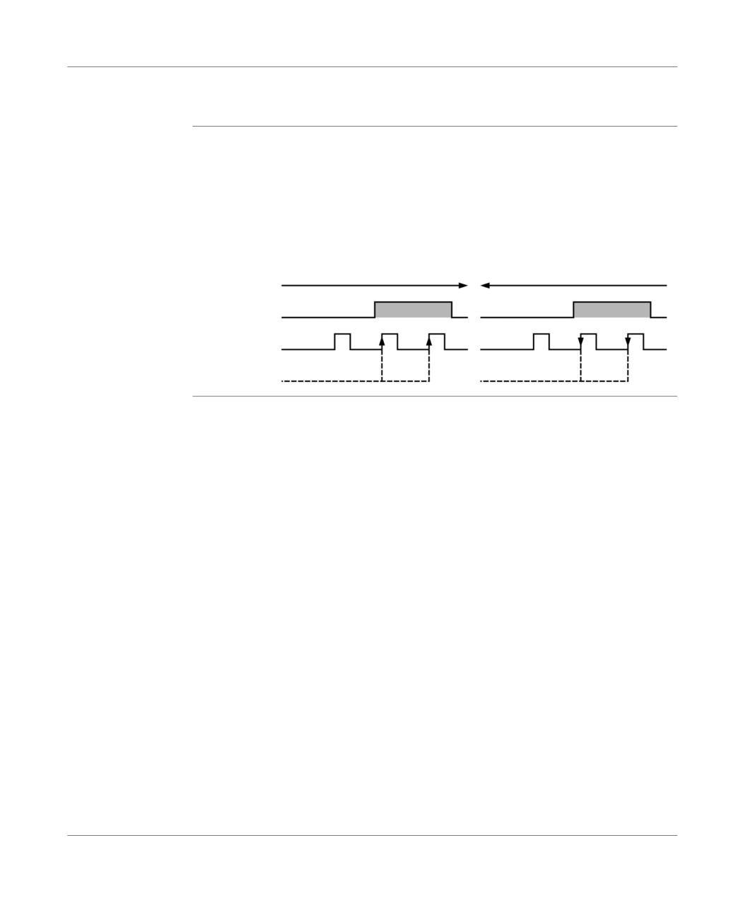
Preset is taken into account:
if the direction is up counting (+): IPres 11 input in status 1 and Top-turn input IZ
rising edge,
if the direction is down counting (-): IPres 11 input in status 1 and Top-turn input
IZ falling edge.
Illustration:
Counting direction
Down counting direction
Physical input IPres 11
Top-turn input IZ
Preset
Preset
TSX DM 37 xxE
257
Up counting functions built in to (10KHz) TSX 37 22 bases
258
TSX DM 37 xxE

Implementing 500Hz up counting
on discrete inputs
28
At a Glance
Aim of this
This chapter deals with the implementation of 500HZ up counting on discrete inputs.
chapter
What's in this
This Chapter contains the following Maps:
Chapter?
Topic
Page
Basic configuration required
260
Types of sensor which can be used on up counting discrete inputs
262
Principal for connecting supplies and sensors
264
Example 1: up counting with inductive detector on the positive logic input
266
Example 2: upcounter with inductive detector on negative logic inputs
267
Example 3: upcounter with incremental encoder with Totem pole outputs
268
Example of sensor and supply cabling with TELEFAST 2 connection base:
269
ABE-7H16R20
General implementation rules
270
TSX DM 37 xxE
259
Implementing up counting on discrete inputs
Basic configuration required
General
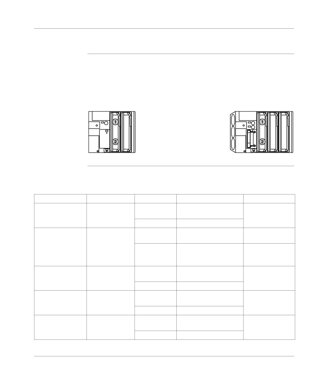
The first four inputs of the standard format module, located in position 1, enable the
up counting functions (described previously) to be carried out.
The characteristics of the sensors which generate the up counting pulses should be
compatible with the characteristics of the inputs of the module located in this position
and which differ according to the module installed.
Illustration:
TSX 37 05/10 PLCs
TSX 37 08/21 PLCs
Recall
Recall of the different standard format input/output modules which are installed in
position 1 of a TSX 37 05/08/10 PLC or which could be installed in position 1 of a
TSX 37 21/22 PLC:
Product reference
Connection
Modularity
Input/output types
PLC’s
TSX DMZ 28 AR
screw terminal
16 inputs (1)
110/120VAC
TSX 37 10 028 AR1
block
IEC 1131 type 2
TSX3721./22.
12 outputs
Relay
TSX DMZ 28 DR
screw terminal
16 inputs
24 VDC, IEC 1131 type
1,
TSX 37 05 028 DR1
block
positive/negative logic
TSX 37 08 056 DR1
12 outputs
Relay
TSX 37 10.028 DR1
TSX 37 10.128 DR1
TSX 3721./22.
TSX DMZ 28 DT
screw terminal
16 inputs
24 VDC, IEC 1131 type
1,
TSX 37 10 128 DT1
block
positive logic
TSX 3721./22.
12 outputs
statistics, 24VDC/0.5A
TSX DMZ 28 DTK
HE10 connector
16 inputs
24 VDC, IEC 1131 type
1,
TSX 37 10 128 DTK1
positive logic
TSX 3721./22.
12 outputs
statistics, 24VDC/0.5A
TSX DMZ 64 DTK
HE10 connector
32 inputs
24 VDC, IEC 1131 type
1,
TSX 37 10 164 DTK1
positive logic
TSX 3721./22.
32 inputs
statistics, 24VDC/0.1A
260
TSX DM 37 xxE
Implementing up counting on discrete inputs
Product reference
Connection
Modularity
Input/output types
PLC’s
TSX DEZ 32D2
screw terminal
32 inputs
24 VDC, IEC 1131 type 2,
TSX3721./22.
block
positive logic
(1) up counting functions possible on these inputs with:
voltage-adapted sensors,
by limiting the frequency, taking the response time of the sensors into account.
TSX DM 37 xxE
261
Implementing up counting on discrete inputs
Types of sensor which can be used on up counting discrete inputs
General points
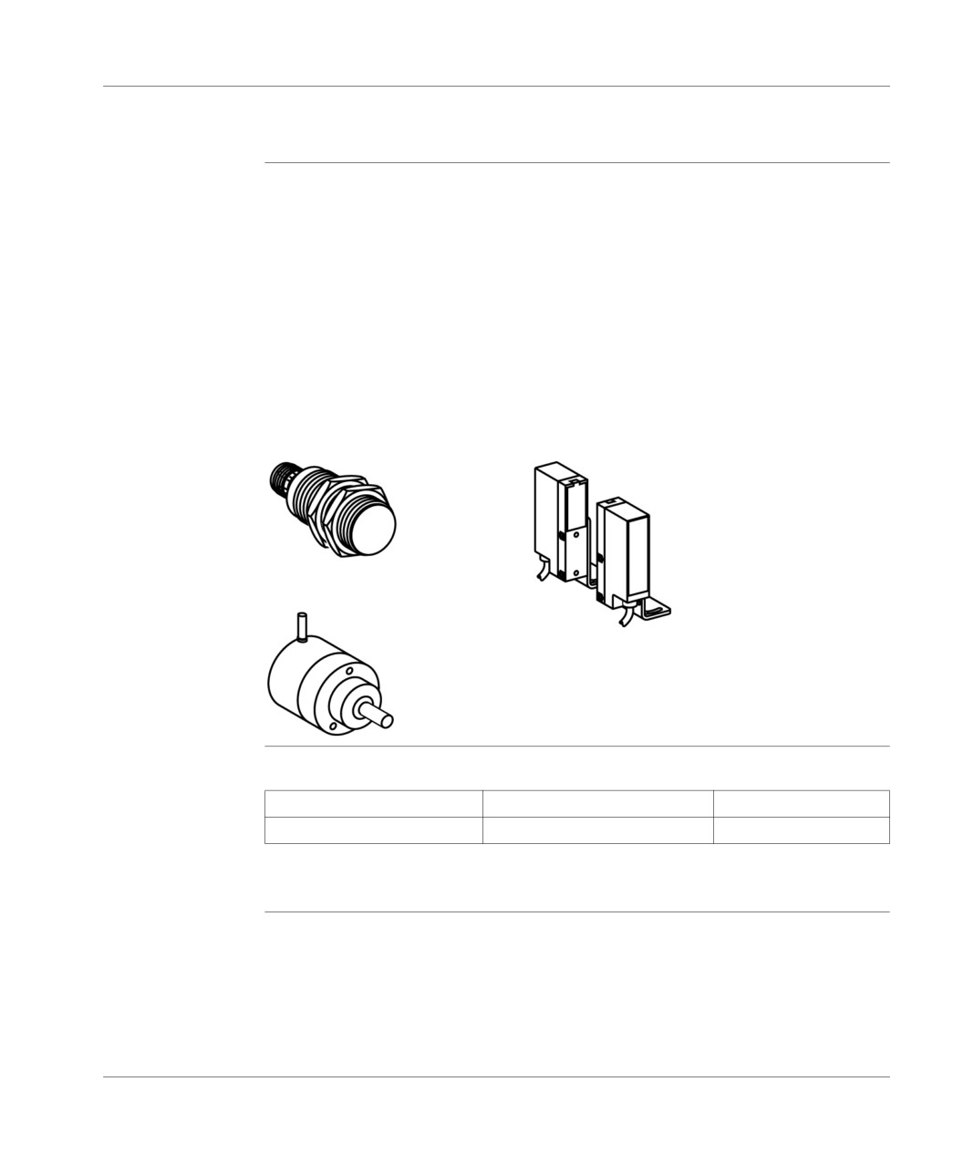
According to the type of module installed in position 1, the (24V DC) up counting
inputs can receive pulses generated by:
an inductive, photoelectric, or other detector:
24V DC supply voltage,
type 2 wires on positive logic (sink) or negative logic (source) inputs,
type 3 PNP wires on positive logic (sink) inputs,
type 3 NPN wires on negative logic (source) inputs,
an incremental encoder with 24V DC outputs of the following type:
open collector NPN,
open collector PNP,
Totem pole.
Illustration: different sensor types
The most
Table:
common type of
Supply voltage
Output voltage
Output mailstop
incremental
encoder which
10...30 V
10...30 V
Totem Pole
can be used on
discrete inputs
262
TSX DM 37 xxE
Implementing up counting on discrete inputs
Compatibility
Table:
recall between
Modules
TSX DMZ 28DR
TSX DMZ 28DT/DTK
the sensors and
TSX DMZ 64DTK
inputs of
3 wire PNP sensor type
Yes (sink configured inputs)
Yes
different
modules
3 wire NPN sensor type
Yes (source configured inputs)
No
2 wire sensor type
Yes (sink or source configured
Yes
inputs)
Incremental encoder with
Yes (sink configured inputs)
Yes
Totem pole output
For sensor/input compatibility, see (TSX Micro Installation manual, Volume 2).
TSX DM 37 xxE
263
Implementing up counting on discrete inputs
Principal for connecting supplies and sensors
Modules with
The supplies and sensors are to be connected directly onto the module’s screw
screw terminal
terminal block.
block connection
264
TSX DM 37 xxE
Implementing up counting on discrete inputs
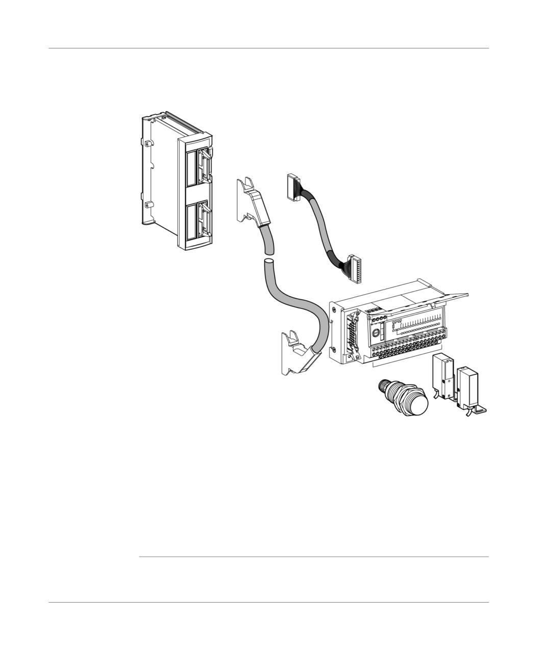
Module with
The supplies and sensors are to be connected using a connection base as
connection by
intermediary for TELEFAST 2 (1) discrete I/O + TSX CDP 102/202/302 stranded
HE10 connector
and sheathed cable or TSX CDP 053/103/203/303/503 (2) wires.
Illustration:
Cable
TSX CDP..2
Base TELEFAST 2
Module with
ABE-7H1.R..
HE10 connector
Cable
TSX CDP..3
Counting sensor
(1) The following TELEFAST 2 connection bases can be used: ABE-7H1.R.. .
(2) TSX CDP 102 : 1m in length,
TSX CDP 102: 1m in length,
TSX CDP 202: 2m in length,
TSX CDP 302: 3m in length,
TSX CDP 053: 0.5m in length,
TSX CDP 103: 1m in length,
TSX CDP 203: 2m in length,
TSX CDP 303: 3m in length,
TSX CDP 503: 5m in length.
TSX DM 37 xxE
265
Implementing up counting on discrete inputs
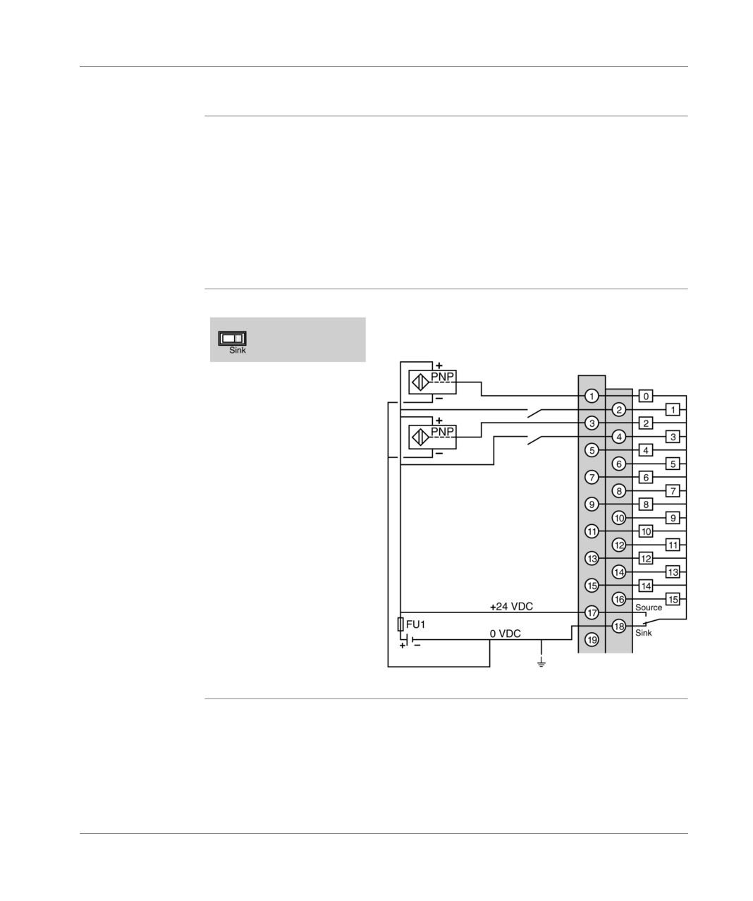
Example 1: up counting with inductive detector on the positive logic input
General
Up counting with inductive proximity detectors on TSX DMZ 28 DR module inputs
located in position 1. The inputs are configured in positive logic (sink).
Channel 0 is configured in up counting with:
%I1.0 input: Upcounter input
%I1/1 input: preset input at 0.
Channel 1 is configured in down counting with:
%I1.2 input: downcounter input,
%I1.3 input: preset input.
Provisional
Illustration:
diagram
Position of switch
on the module
TSX DMZ 28DR Inputs
Counting channel sensor
Preset channel sensor 0
Down counting channel sensor 1
Preset channel sensor 1
FU1=fuse 0.5A with fast blow fuse
266
TSX DM 37 xxE
Implementing up counting on discrete inputs
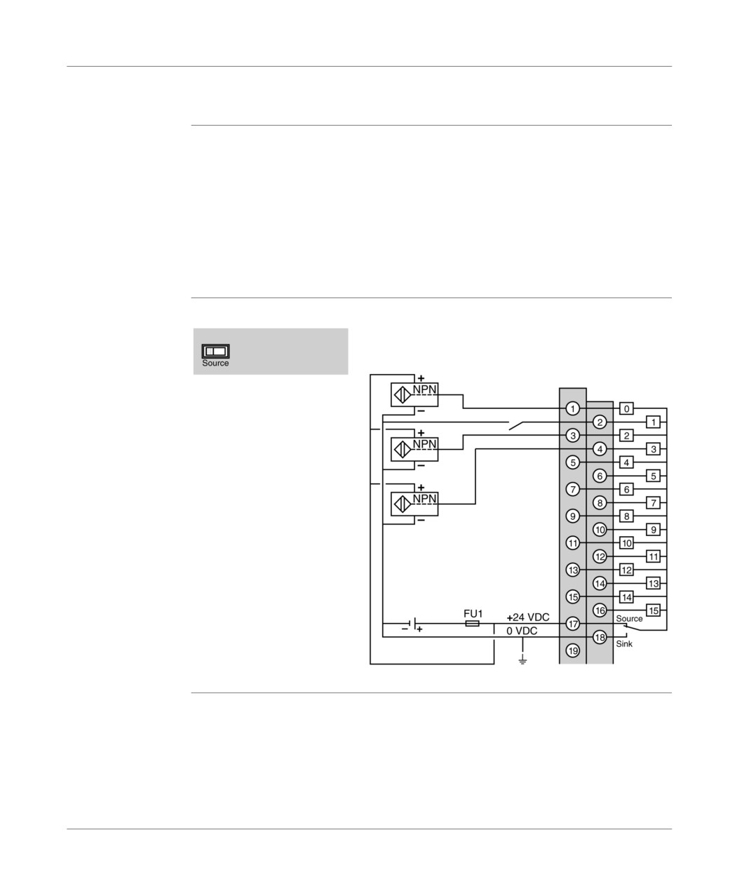
Example 2: upcounter with inductive detector on negative logic inputs
General
Upcounter with inductive proximity detectors on TSX DMZ 28 DR module inputs
located in address 1. The inputs are configured in negative logic (source).
Channel 0 is configured in up/down counting with:
%I1.0 input: upcounter/downcounter input
%I1.1 input: up counting direction input, status 1 upcount, status 0 downcount.
Channel 1 is configured in up/down counting with:
%I1.2 input: upcounter input
%I1.3 input: downcounter input,
Provisional
Illustration:
diagram
Position of switch
on the module
TSX DMZ 28DR Inputs
Counting sensor/
Down counting channel 0
Sensor direction of
counting channel 0
Counting channel
sensor 1
Down counting
channel sensor 1
FU1=fuse 0.5A with fast blow fuse
TSX DM 37 xxE
267
Implementing up counting on discrete inputs
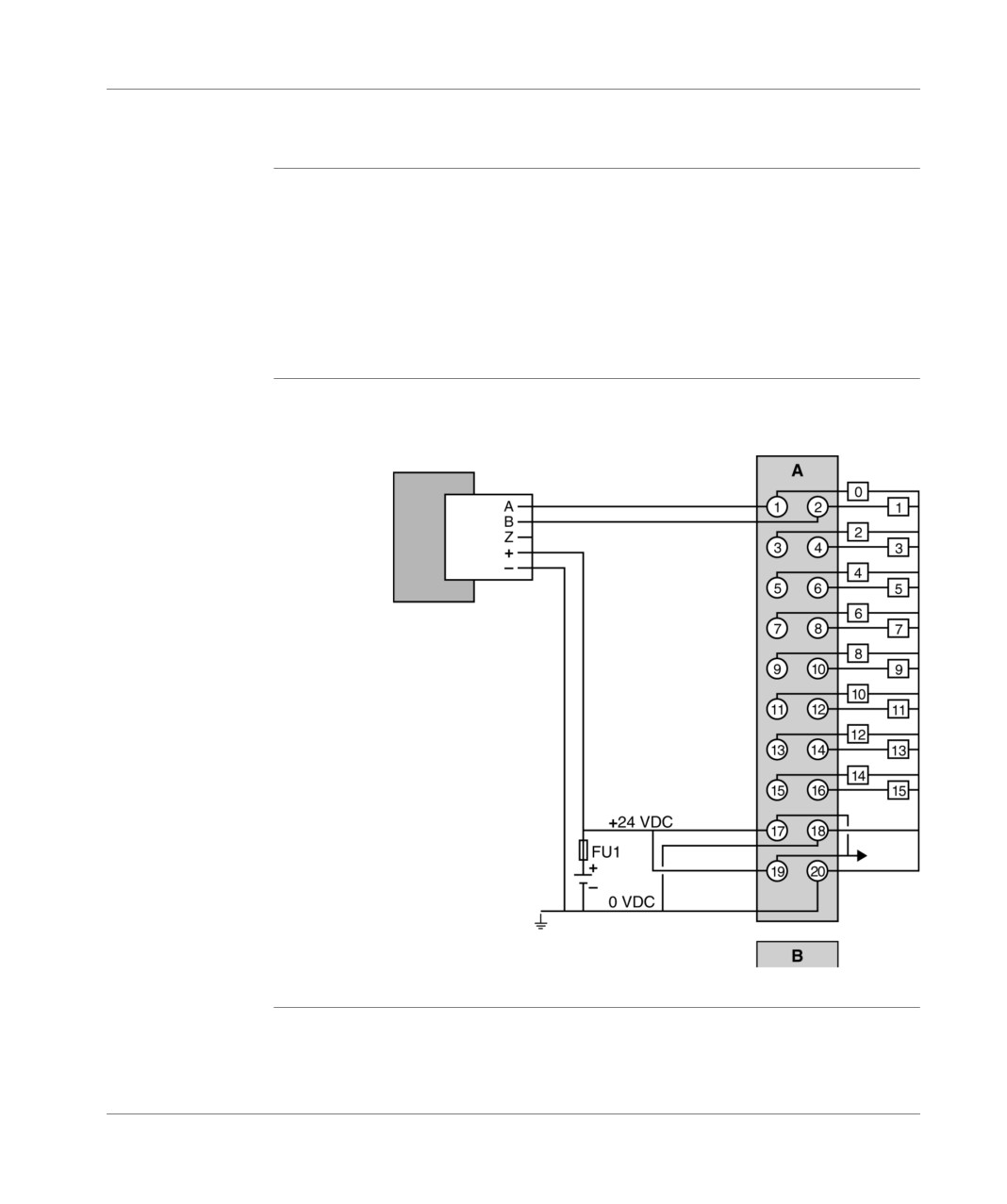
Example 3: upcounter with incremental encoder with Totem pole outputs
General
Upcounting from a Totem pole-output incremental encoder on TSX DMZ 28DTK
module inputs located at address 1. The inputs are in positive logic.
The channel is configured in up/down counting with:
%I1.0 input: signal A of the incremental encoder,
%I1.1 input: signal B of the incremental encoder.
Channel 1 is not configured in upcounting, but the corresponding %I1.2 and %I1.3
inputs can be used as event inputs.
Provisional
Illustration:
diagram
TSX DMZ 28DTK Inputs
Coder
Supply.
FU1 = 0.5A fast blow fuse
268
TSX DM 37 xxE
Implementing up counting on discrete inputs
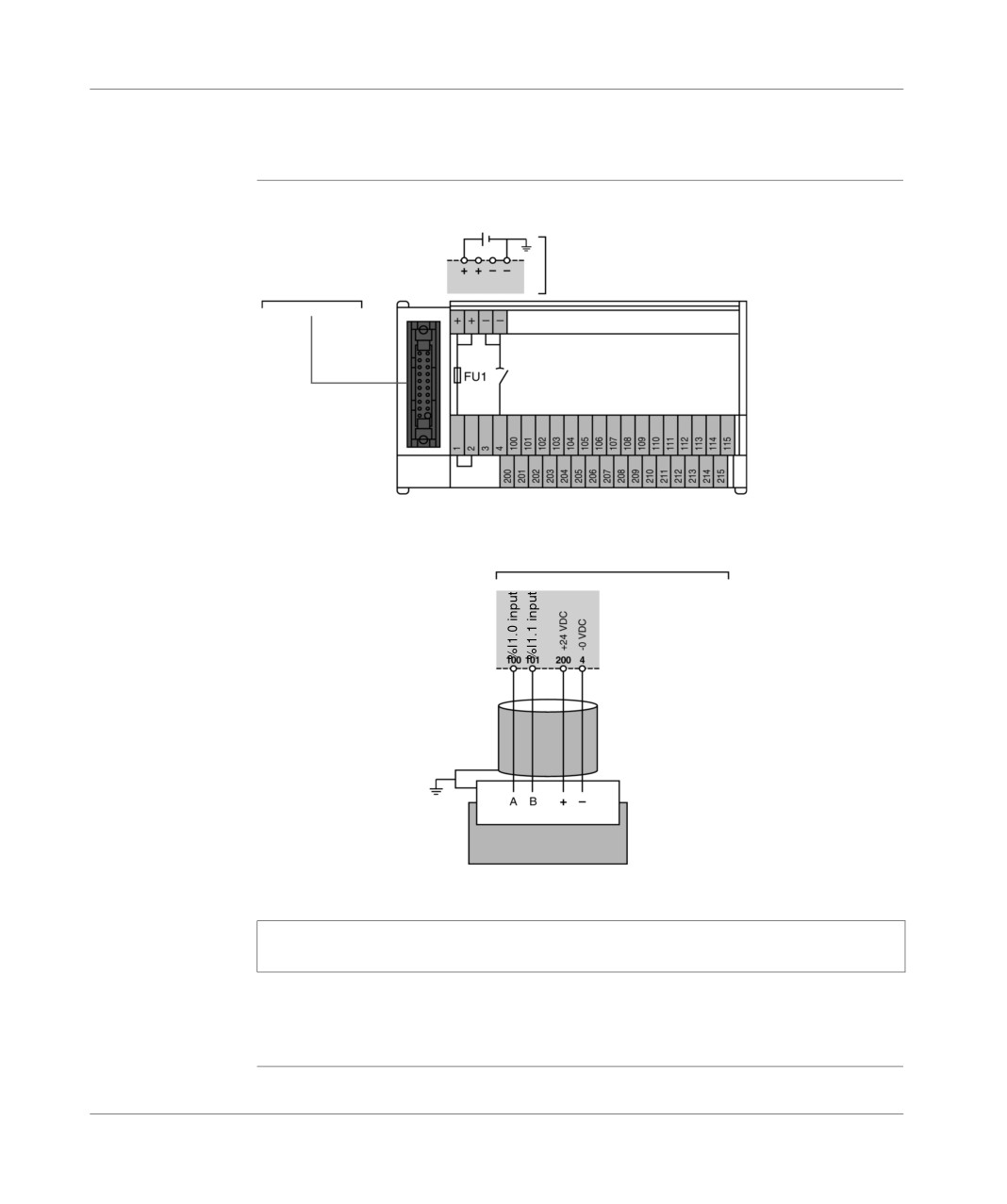
Example of sensor and supply cabling with TELEFAST 2 connection base: ABE-
7H16R20
Principle
Diagram
connection to the
connection of the 24 VDC
input/output
encoder and sensor supply
module in position 1
ABE-7H16R20 (2)
TSX CDP ... (1)
FU1 = fast blow fuse
0.5A incorporated in the base
encoder connections on the TELEFAST 2 base
Channel 0 encoder
Note: If an encoder is used, use a TELEFAST 2 base without display LED for the
status of each ABE-7H••R•0 channel.
(1) Connection cable: TSX CDP 102/202/302 or
connection wire: TSX CDP 053/103/203/303/503.
(2) See (TSX Micro Installation manual, Volume 2, connection base).
TSX DM 37 xxE
269
Implementing up counting on discrete inputs
General implementation rules
General points
The general implementation rules are identical to those of the discrete inputs/
outputs (TSX Micro Installation manual, Volume 2).
The general software implementation rules and the language objects associated
with the different counting functions are developed in the Manuals TLX DS 57 PL7
••E tome 2.
Note: When the inputs of a discrete module are used in upcounting and/or
downcounting mode, outside incremental encoder interface configuration, it is
imperative that the filtering on these inputs be suppressed for the 500Hz
upcounter.
When there is a warm restart, the current value of the upcounter is reset to 0.
270
TSX DM 37 xxE

Implementing 10KHz upcounter
onto TSX 37-22 bases
29
At a Glance
Aim of this
This chapter deals with the implementation of the 10KHz upcounter onto TSX 37-22
chapter
bases.
What's in this
This Chapter contains the following Maps:
Chapter?
Topic
Page
Basic configuration required
272
Type of sensors which can be used on the upcounter inputs
273
Characteristics
274
Pin configuration of the 15-pin SUB-D (channels 11 and 12) connectors
276
Connecting an incremental encoder on channel 11
279
PLC/encoder connection
281
Connecting supply and preset sensor
284
Connecting counting sensors on channel 11 and 12
285
Connecting supplies and sensors on channel 11
286
Connecting supply and sensors on channel 12
287
General rules for implementation
288
TSX DM 37 xxE
271
Implementing 10KHz upcounter onto TSX 37-22 10 bases
Basic configuration required
General
A TSX 37-22 base has 2 built-in upcounting channels which make it possible to carry
outupcounting functions (See Overview of different counting functions, p. 235) .
For each upcounting channel, a 15-pin SUB-D connector assembles:
the connection points together with the various sensor types which generate the
counting pulses,
the connection points to the preset auxiliary inputs,
the supply connection points.
Illustration
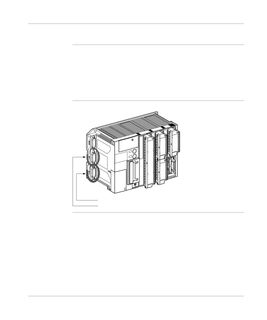
Display of the connectors on TSX PLC:
channel 12 (CNT2 connector)
channel 11 (CNT2 connector)
272
TSX DM 37 xxE
Implementing 10KHz upcounter onto TSX 37-22 10 bases
Type of sensors which can be used on the upcounter inputs
Channel 11 and
The upcounter inputs of channels 11 and 12 can receive pulses generated by every
channel 12
type:
of inductive, photoelectric, or other detector:
24VDC output voltage,
2 wires or 3 wires from PNP or NPN types,
from sensors with 5VDC output voltage.
Channel 11 only The channel 11 upcounter inputs can also receive pulses which are generated by
an incremental encoder.
Illustration
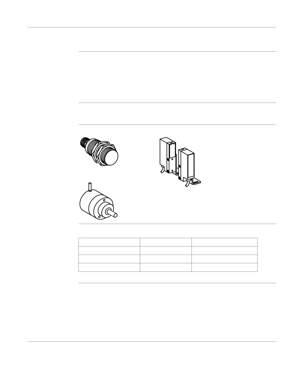
Different types of sensors:
The most
Summary table:
common types of
Supply voltage
Output voltage
Type of output mailstop
incremental
encoders can be
5V
differential 5V
RS 422 line transmitter
used for
10...30 V
10...30 V
Totem pole.
upcounting on
10...30 V
differential 5V
RS 422 line transmitter
channel 11
TSX DM 37 xxE
273
Implementing 10KHz upcounter onto TSX 37-22 10 bases
Characteristics
General
Table of characteristics:
Characteristics
Maximum counting frequency
10KHz
Operational Temperature
0 to 60°C
Input/earth dielectric rigidity or internal logic and
1000V effective - 50/60Hz - 1mm
input
Hygrometry
5% to 95 % excluding condensation
Storage temperature
-25° to +70°C
Operational altitude
0 to 2000 meters
274
TSX DM 37 xxE
Implementing
10KHz upcounter onto TSX
37-22 10 bases
Input
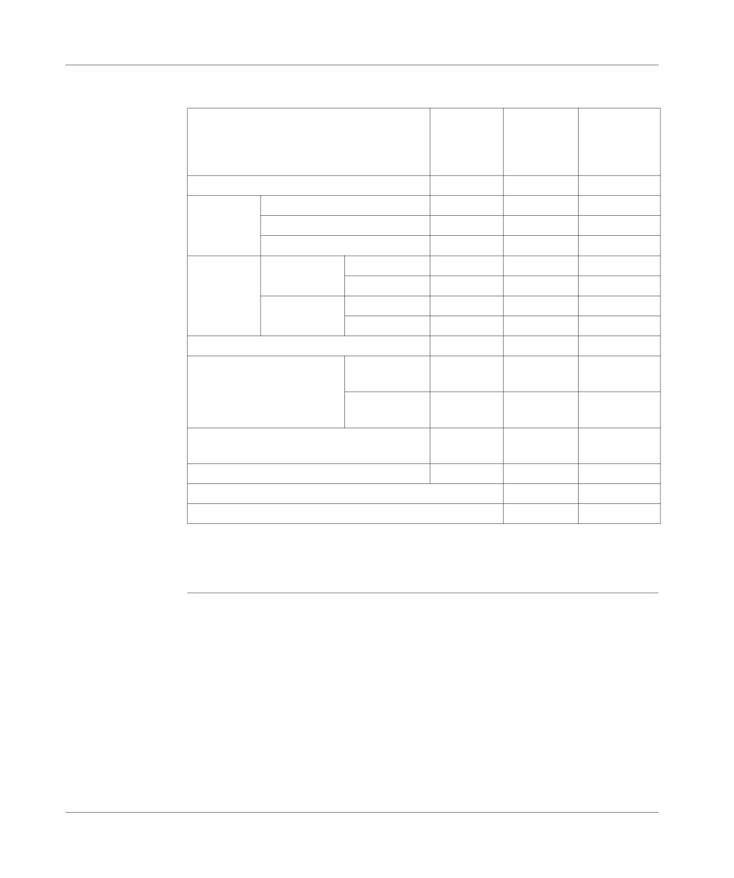
Table of characteristics:
characteristics
Inputs
5V
24V DC
24V DC
upcounter
upcounter
preset
or RS 422
(IA/IB/IZ)
(IPres11/
(IA/IB/IZ)
IPres12)
Logic
Positive
Positive
Positive
Nominal
Voltage
5V
24V
24V
values
Current
3mA
8.7mA
10mA
Sensor supply
2...5,5 V
19...30 V
19...30 V
Thresholds
In state 1
Voltage
>= 2.1 V
>= 11 V
>= 11 V
Current
> 2 mA (1)
> 6 mA (2)
> 2.5 mA (2)
In state 0
Voltage
<= 1 V
<5V
<5V
Current
< 0.65mA
< 2 mA
< 1.4mA
Input impedance
> 270 Ohms
2.7 KOhms
2.4 KOhms
Response time
Status 1
to
0
15 micro
15 micro
200 micro
seconds
seconds
seconds1ms
Status 1
to
0
1...15 micro
1...15 micro
200 micro
seconds
seconds
seconds1ms
Input type
Current
Current
Resistive
ducts
ducts
Compliance with IEC 1131-2
-
Type 1
Type 2
(3) 2 wire DDP compatibility
-
Yes/Yes
(3) 3 wire DDP compatibility
-
Yes/Yes
(1) for U = 2.4 V,
(2) for U = 11V.
(3) See (TSX Micro Installation manual, Volume 2).
TSX DM 37 xxE
275
Implementing 10KHz upcounter onto TSX 37-22 10 bases
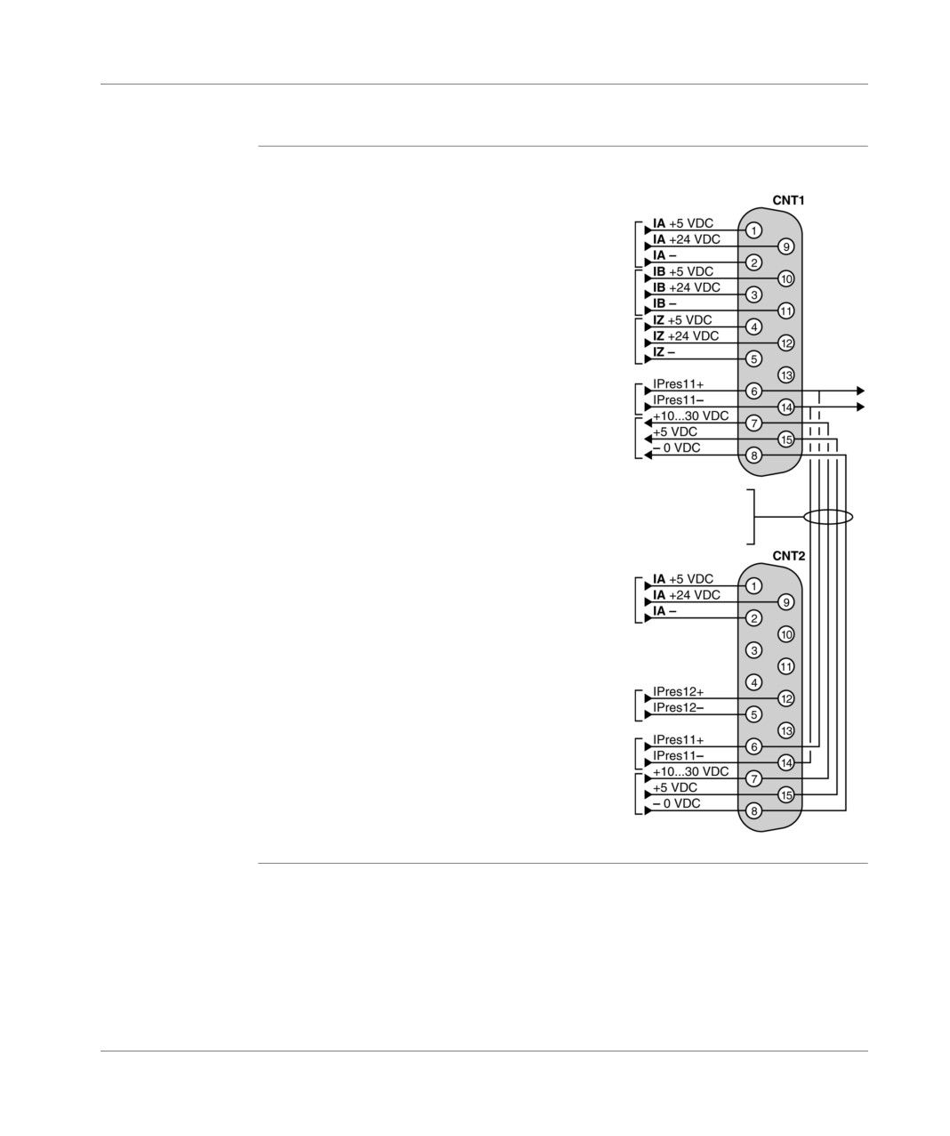
Pin configuration of the 15-pin SUB-D (channels 11 and 12) connectors
Provisional
Illustration:
diagram
channel 11 A signal input
channel 11 B signal input
channel 11 Z signal input
Channel 11 preset input
Supply for encoder
Information report internal links
from CNT2 connectors to the connector
CNT1 to make connection easier
encoder
channel 12 A signal input
Channel 12 preset input
Channel 11 preset input
External 10…30VDC or
5VDC supply for encoder
276
TSX DM 37 xxE

Implementing
10KHz upcounter onto TSX 37-22 10 bases
CNT1 connector
5VDC signals table:
(channel 11)
5VDC signals
Pins
IA + (channel 11) input
1
IA - (channel 11) input
2
IB + (channel 11) input
10
IB - (channel 11) input
11
IZ + (channel 11) input
4
IZ - (channel 11) input
5
Supply:
+ 5VDC
15
-0VDC
8
5VDC signals table:
24VDC signals
Pins
IA + (channel 11) input
9
IA - (channel 11) input
2
IB + (channel 11) input
3
IB - (channel 11) input
11
IZ + (channel 11) input
12
IZ - (channel 11) input
5
Preset inputs:
IPres 11 + (channel 11)
6
IPres 11 - (channel 11)
14
Encoder supply:
+ 24VDC
7
-0VDC
8
TSX DM 37 xxE
277

Implementing 10KHz upcounter onto TSX 37-22 10
bases
CNT2 connector
5VDC signals table:
(channel 12)
5VDC signals
Pins
IA + (channel 12) input
1
IA - (channel 12) input
2
External supply:
+ 5VDC
15
-0VDC
8
24VDC signals table:
24VDC signals
Pins
IA + (channel 12) input
9
IA - (channel 12) input
2
Preset inputs:
IPres 12 + (channel 12)
12
IPres 12 - (channel 12)
5
IPres 11 + (channel 11)
6
IPres 11 - (channel 11)
14
External supply:
+ 24VDC
7
-0VDC
8
278
TSX DM 37 xxE
Implementing 10KHz upcounter onto TSX 37-22 10 bases
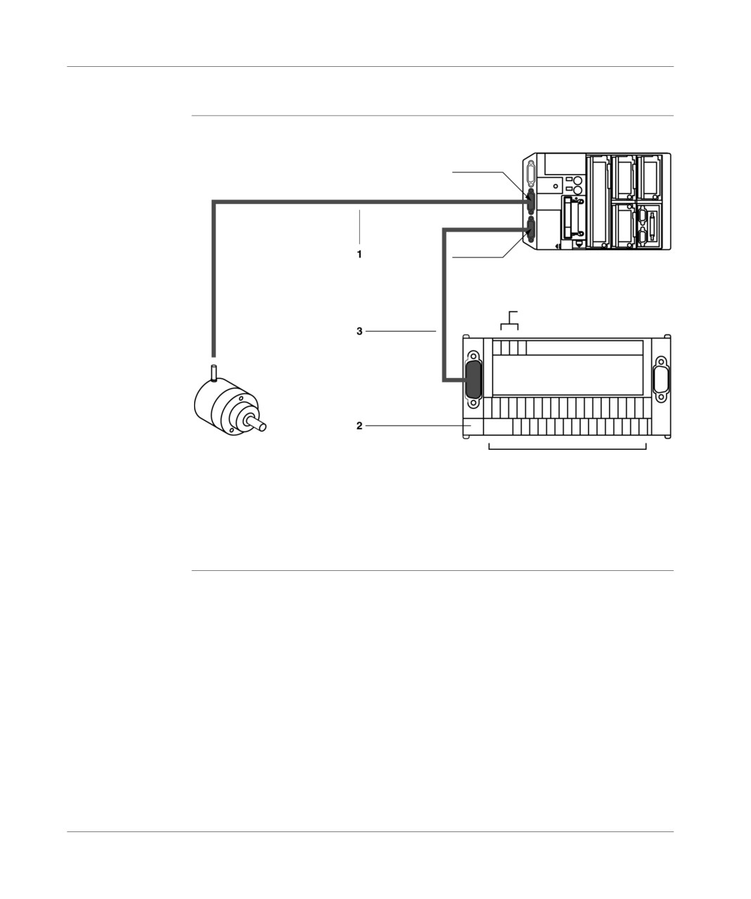
Connecting an incremental encoder on channel 11
Connection
Illustration:
principle
CNT1
CNT2
TSX 37-22 PLC
Connection:
sensor supply (24VDC)
TELEFAST 2
ABE-7CPA01
Incremental encoder
Connections:
encoder supply (5VDC or 10…30VDC),
channel 11 preset sensor, if required,
grounded.
TSX DM 37 xxE
279

Implementing 10KHz upcounter onto TSX 37-22 10 bases
Description of
Table of addresses:
the different
Addresses
Description
connection
1
Connector for connecting the encoder to the CNT1 connector which is located
components
on the TSX 37-22 PLC. Having taken the different encoder types into account,
it is up to you to make this connection which comprises:
a connector for connecting to the encoder (to be defined according to the
encoder connector which is used, usually DIN 12-female pin connector),
a standard male 15-pin SUB-D connector for connecting the CNT1 from the
TSX 37-22 PLC. Element provided as a separate element under the
reference TSX CAP S15,
a cable:
with twisted pairs (gauge 24) and shield for an encoder with line
transmitter outputs with RS 422 standard,
bundled cables (gauge 24) with shield for an encoder with Totem pole
outputs.
The shield of the cable will be "braid and steel strip"; the contact of the
"braid and steel strip" with the ground of each connector must be secured
by clamping down the whole diameter of the cable.
The connection of this cable on these two connectors varies according to
the type of encoder supply (5VDC or 10…30VDC) and the output type
(RS 422, Totem pole, PNP or NPN open collector).
2
TELEFAST 2 connection base: ABE-7CPA01.
It enables quick connection:
of the 24VDC supply designed for sensors other than the encoder,
of the encoder supply and the channel 11 preset sensor if the latter is
required in order for the application to operate.
3
TSX CCP S15 cable, 2.5 meters long, with a 15-pin standard SUB-D connector
at each end. This cable is made up of 15 cables, 0.2mm wide2(gauge 24),
which are linked point-to-point + external braid and steel strip shield and
ensures the link between the CNT2 connector from the TSX 37-22 PLC and the
TELEFAST 2 (ABE-7CPA01) connection base.
Note: Connecting an incremental encoder to the CNT1 connector of the TSX37-22
PLC can be carried out with the help of a TSX TAP S15•• cabling accessory.
280
TSX DM 37 xxE
Implementing 10KHz upcounter onto TSX 37-22 10 bases
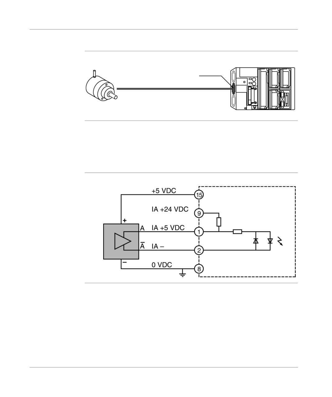
PLC/encoder connection
Illustration
Incremental encoder connected to a TSX 37-22 PLC:
CNT1
Wire 1
Incremental encoder
TSX 37-22 PLC
Example: PLC/
Encoder characteristics:
encoder
supply voltage: 5VDC,
connection with
output voltage: differential 5VDC,
RS 422 line
output mailstop: RS 422 standard line transmitter.
transmitter
outputs
Provisional
Illustration:
diagram
PLC
Encoder
CNT1 connector
TSX DM 37 xxE
281
Implementing 10KHz upcounter onto TSX 37-22 10 bases
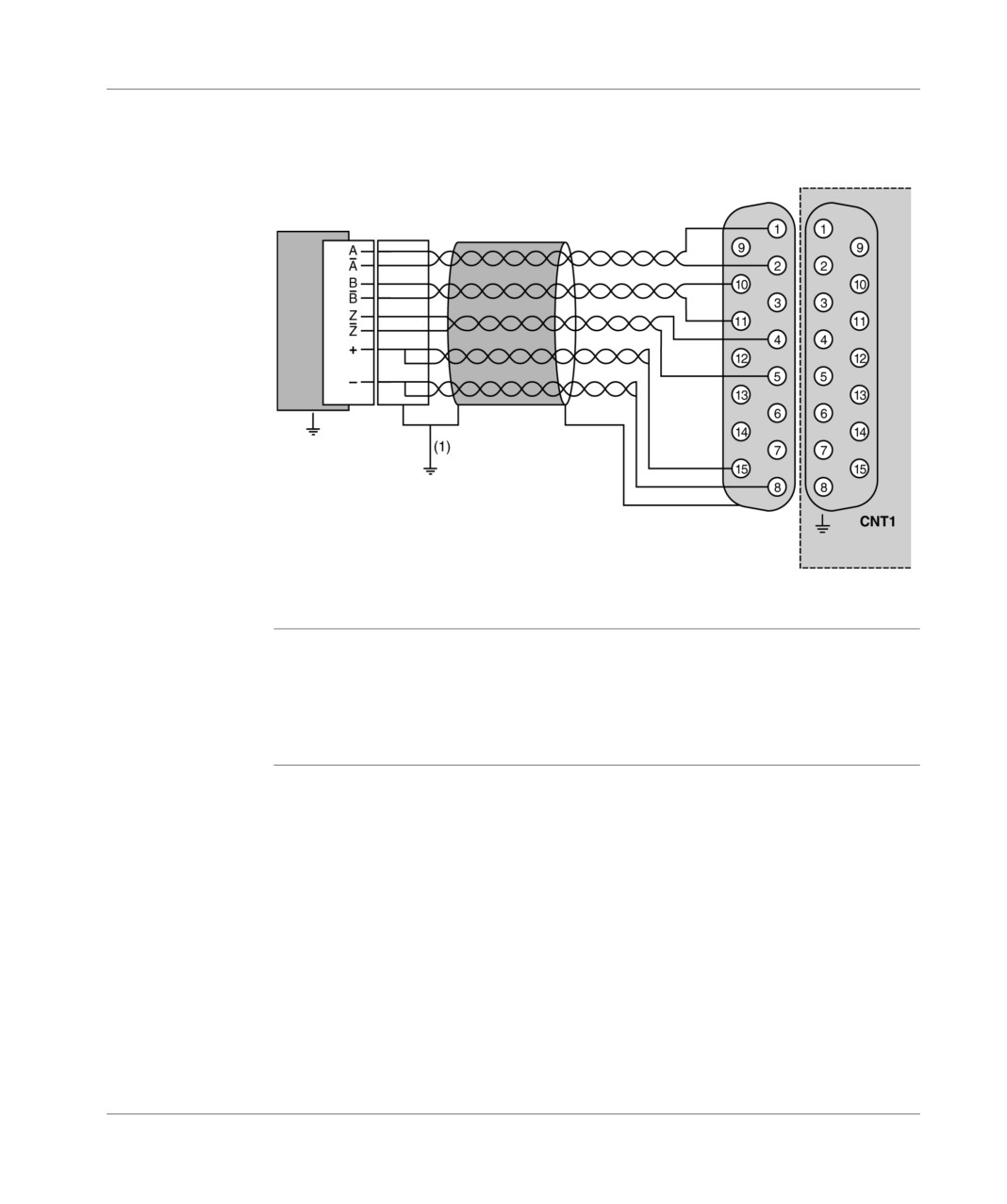
Connection
Illustration:
diagram
15-pin SUB-D
male
female
Connector
Wire 1
Encoder
DIN
(encoder/PLC connection
Supp
PLC
(1) if the encoder is insulated from the mass, the link to ground should be made as
described above.
Example: PLC/
Encoder characteristics:
encoder
supply voltage: 10...30VDC,
connection with
output voltage: 10...30VDC,
Totem pole
output mailstop: Totem pole.
outputs
282
TSX DM 37 xxE