TSX Micro PLCs TSX 3705/3708/3710/3720. Implementation Manual (Volume 1) - page 5
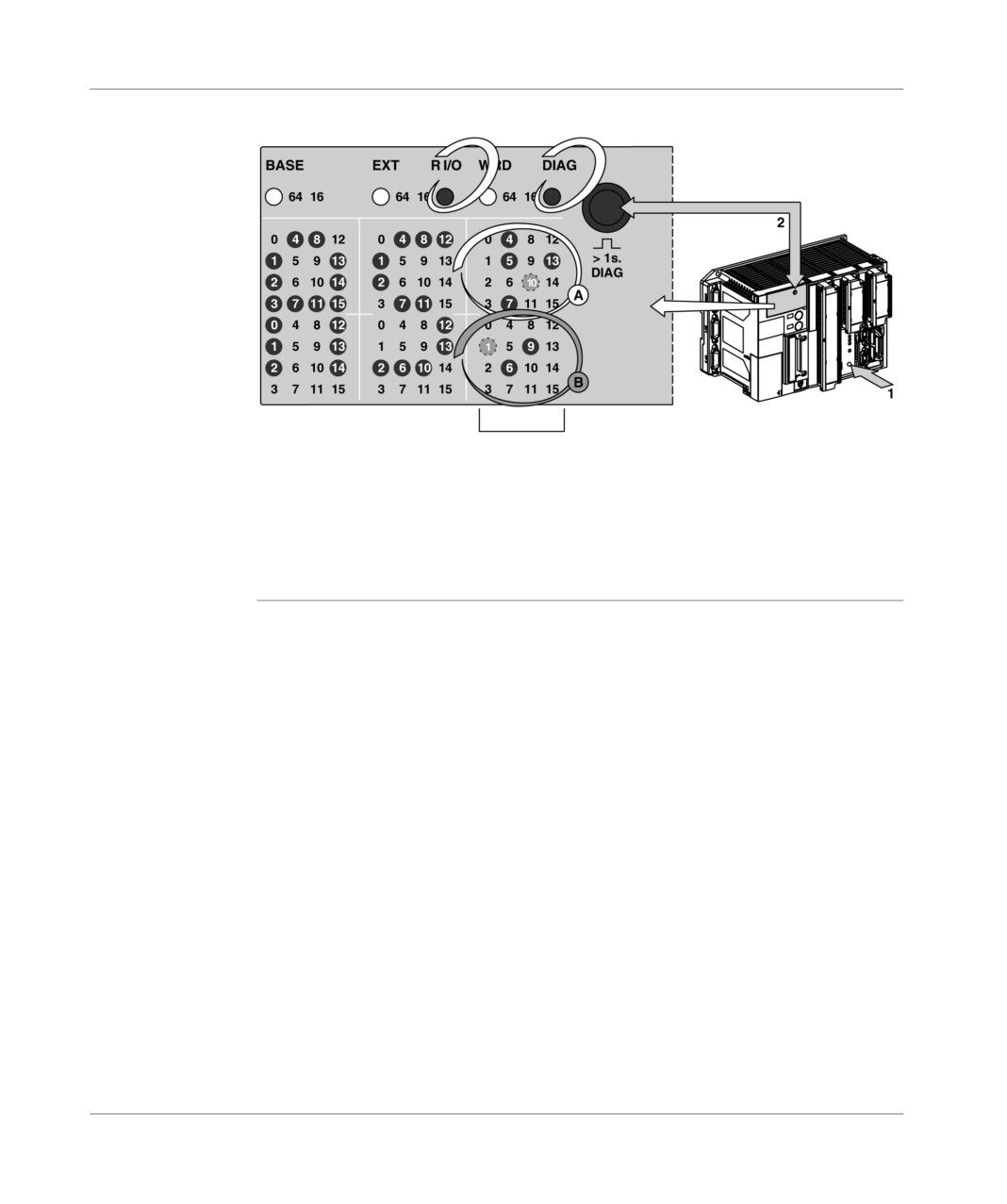
Display panel
Example
Illustration:
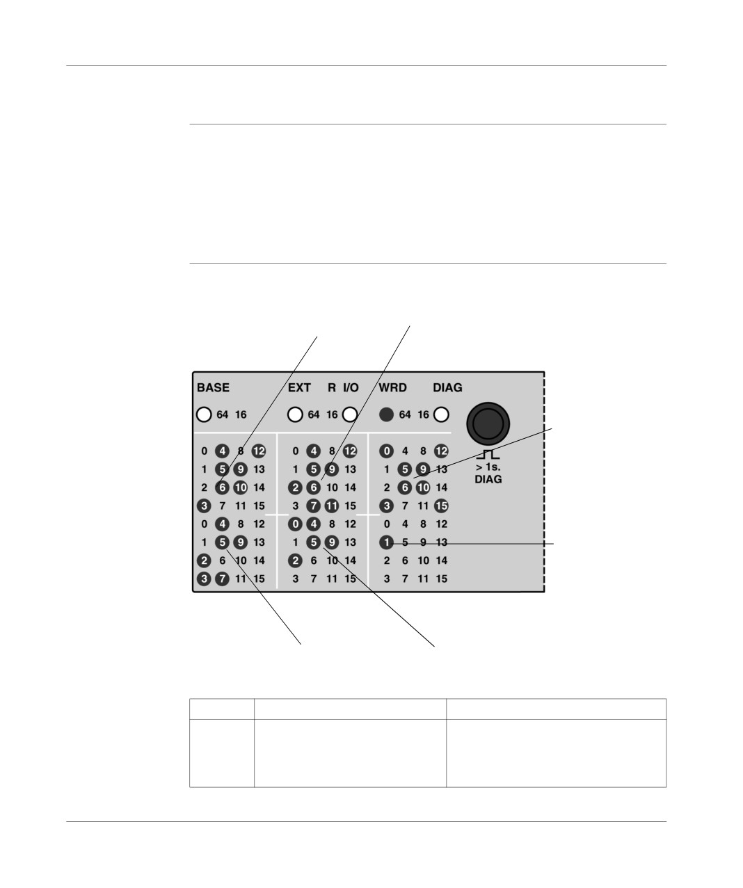
Presence of slaves on the AS-i bus
In the example below:
the slaves with the addresses 4, 5, 7, 13, 22(6+16) and 25 (9+16) are operating
normally (LEDs permanently on),
the slaves with addresses 10 and 17 (1+16) are faulty (blinking LEDs),
the LEDs which are not on represent the empty addresses.
TSX DM 37 xxE
163

Display panel
Display of the status of the input/output bits for each slave (R I/O mode)
Introduction
The PLC display panel enables the status of the input/output bits of each slave on
the bus to be displayed.
Procedure for
Carry out the following steps:
access
Step
Action
1
Initial status of display panel:
local input/output display mode (Base or EXT LEDs on).
2
A short press on the push button (1) on the TSX SAZ 10 module switches to
R I/O mode with display:
of an address of a slave (1 to 31) on the two panels on the left-hand side
(numerical display),
of the status of the input/output bits relating to the slave displayed, on the
panel on the right-hand side (LED on = bit set to 1, LED off = bit set to 0 or
no inputs / outputs). The LEDs (0 to 3) at the top show the status of the input
bits of the slave (maximum of 4 input bits per slave); the LEDs (0 to 3) at the
bottom show the status of the output bits of the slave (maximum of 4 output
bits per slave),
of the direction of movement in all the slaves, shown by three LEDs being
lit (see Incrementation of the slave number in ascending or descending
order, p. 166): if LEDs 8,13 and 10 are on, movement in the group of slaves
takes place in ascending order; if LEDs 12, 9 and 14 are on, movement
takes place in descending order.
3
Pressing briefly several times in succession on the push button (2) of the
centralized display makes it possible to change the number of the slave in
ascending order (1 -> 31) or descending order (31 -> 1) depending on the
direction of movement.
Changing direction (ascending or descending) is achieved by a long press on
the push button (1) on the TSX SAZ 10 module.
4
Returning to the initial status of the display panel is achieved by a short press
on the push button (1) on the TSX SAZ 10 module.
164
TSX DM 37 xxE
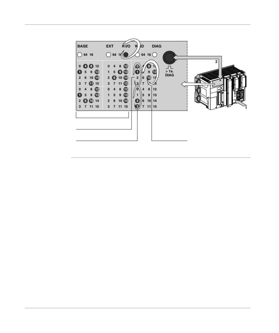
Display panel
Illustration
input/output bits of each slave:
Slave number (31)
State of input bits
(%I\4.0\31.0 & %I\4.0\31.1 = 1
Area showing the direction of
States of output bits
movement in the group of slaves
(%Q\4.0\31.2 & %Q\4.0\31.3 = 1)
(here, ascending)
TSX DM 37 xxE
165
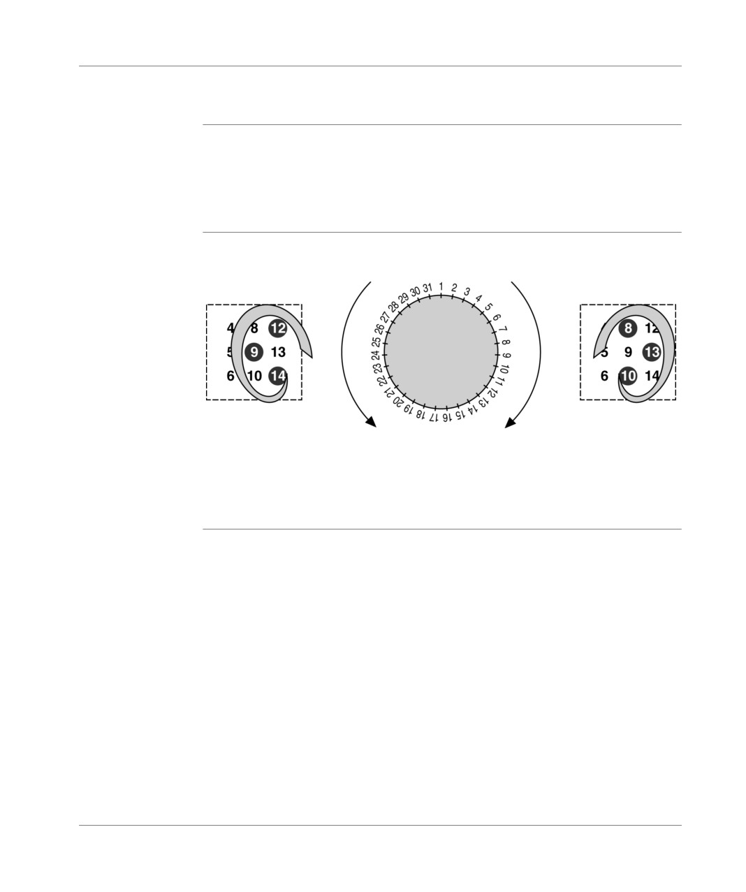
Display panel
Incrementation of the slave number in ascending or descending order
General points
When the PLC display block is in R I/O mode (display of input/output bits of each
slave), the user can scan the slaves in ascending (1->31) or descending (31->1)
order. The direction is shown by 3 lit LEDs at display panel level, as indicated on the
following diagram. The direction can be changed with along press on the push
button of the TSX SAZ 10 module.
Principle
Diagram
LEDs 12, 9, 14 on
LEDs 8, 13, 10 on
incrementation of
incrementation of
in descending
in ascending
the slave number
the slave number
order
order
in descending
in descending
order
order
166
TSX DM 37 xxE
Display panel
Specific standard functions
At a Glance
Each TSX 37 PLC and TSX SAZ 10 module features a push button on their front
panels, enabling the operating mode of the central display unit to be changed. The
discrete inputs can be used to carry out the same function as these push buttons.
By default, any changes to the operating mode of the display block are made by the
push buttons.
Offset push
To replace the push button of the central unit with a discrete input, simply:
button of the
initialize the contents of the %SW99 word by program or by setting at the address
display block
of the required input,
validate the function of this input by setting the system bit %S99 to 1, thus
rendering the push button inactive.
The system word %SW99 indicates the geographic address of the discrete input
assigned in place of the push button.
By default, the word %SW99 contains the address corresponding to input %I1.10
(input 10 of the module located in position 1) as the dedicated input for this function.
It is however possible to modify the assignment of the dedicated input for this
function by program (see(Reference manual PL7, volume 2, system words)).
Offset push
To replace the push button of the AS-i module with a discrete input, simply:
button of the
initialize the contents of the %SW98 word by program or by setting at the address
module AS-i TSX
of the required input,
STZ 10
validate the function of this input by setting the system bit %S98 to 1, thus
rendering the push button inactive.
The system word %SW98 indicates the geographic address of the discrete input
assigned in place of the push button.
By default, the word %SW98 contains the address corresponding to input %I1.11
(input 11 of the module located in position 1) as the dedicated input for this function.
It is however possible to modify the assignment of the dedicated input for this
function by program (see(Reference manual PL7, volume 2, system words)).
TSX DM 37 xxE
167
Display panel
Management of the battery LED (BAT)
Principle
The switching on of the BAT status LED, which indicates the absence of or an error
in the backup battery, may be inhibited per program or by an adjustment, by setting
the system bit %S66 to 1.
The table below describes the different statuses of the %S66 bit.
Bit No.
Description
%S66
= 0: BAT LED is on when the back-up battery is absent or faulty.
= 1: BAT LED off.
168
TSX DM 37 xxE
Display of language objects
18
At a Glance
Aim of this
This chapter deals with the display of language objects.
Chapter
What's in this
This Chapter contains the following Maps:
Chapter?
Topic
Page
WORD mode
170
Word of order and status : %SW67
171
Index word : %SW68
173
Word %SW69
175
Example : word display in hexadecimal mode
176
Example : word display in binary mode
178
Example : display of the internal bit status
181
Example: Display of remote inputs/outputs on TSX 07
183
TSX DM 37 xxE
169
Display of language objects
WORD mode
General
The Display of language objects comes from the 3 panels of 32 LEDs, which allow
the display of the value of 256 bits or 16 words max., when the WORD mode is
activated. The display of the words can be binary, which allows 4 consecutive words
or hexadecimal alphanumerics to be displayed. In this case, one single word is
displayed with most/least significant alternation.
It is possible to display the %M, %Si or %Xi bits, the %MWi, %SWi or %KWi words
and the remote discrete inputs/outputs delivered by TSX 07 PLCs.
Principle
The WORD mode is activated by setting the %S69 bit system to 1, which is signaled
by the WRD LED being lit. In this mode, the push button will scroll the value
displayed (most/least significant in the hexadecimal base) or the values displayed
(4 words then 4 following words etc. in the binary base).
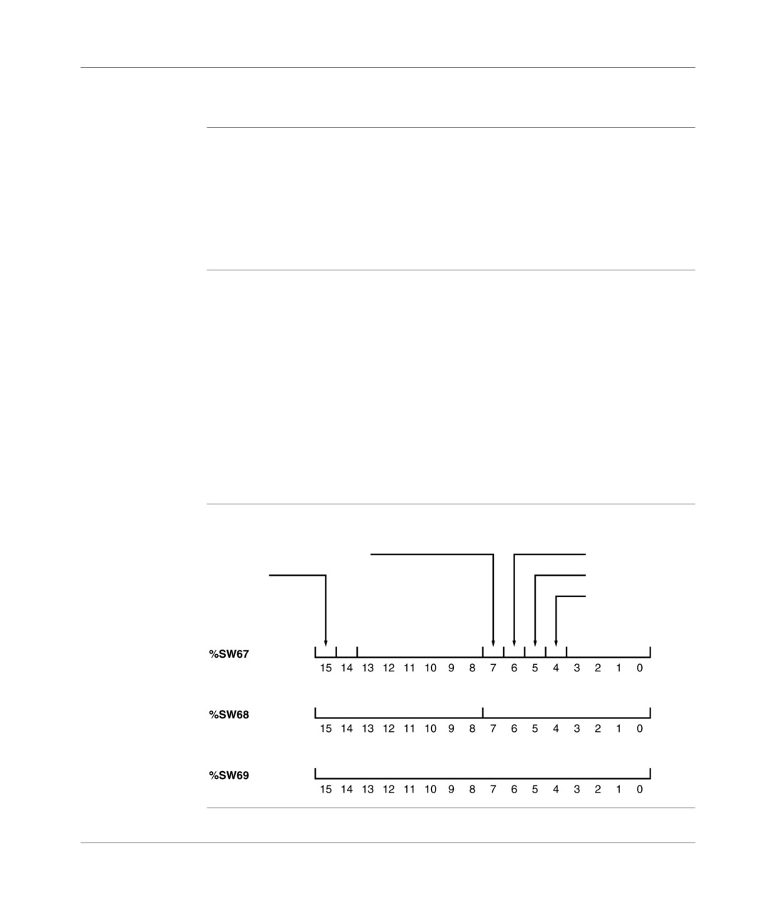
The installation of the display is performed by the 3 system words %SW67, %SW68
and %SW69, which define respectively :
the order information and the mode status (type of objects displayed, display
base etc.),
the current index of the displayed objects (64 bit group number or word order in
the table defined by the maximum index and the word %SW69) and the maximum
index (number of words in the word table),
the number of the first word in the word table.
Illustration
Principle diagram:
Most significant display
Least significant display
Error
Direction of movement
Binary/hexadecimal
Reserved
Type of object
maximum index
Current index
Number of first object
170
TSX DM 37 xxE

Display of language objects
Word of order and status : %SW67
Type of objects
These 4 bits configure the type of objects to be displayed:
(0 to 3 bits)
0 : %MWi (default),
1 : %SWi,
2 : %kWi,
8 : %Mi,
9 : %Si,
A : %Xi,
B : %I and %Q of the TSX 07 PLCs.
Binary/
This bit configures the display base of the word objects:
Hexadecimal
0 : Binary,
(bit 4)
1 : Hexadecimal (default),
Direction of
This bit configures the direction of movement in the word table or in the bit group:
movement
the movement is caused by pressing the push button:
(bit 5)
0 : positive direction, i.e. ascending direction of index (default),
1 : negative direction, i.e. descending direction of index.
Most/least
These bits configure the way of displaying a word in hexadecimal mode:
significant
Most significant
Least significant
Meaning
display
display (bit 7)
display (bit 6)
(bits 6 and 7)
0
0
Combination prohibited! Causes error bit to
be set at 1 (bit 15).
0
1
Permanent display of the least significant
byte.
1
0
Permanent display of the most significant
byte.
1
1
Alternating display of the least significant
byte (2s duration) and the most significant
byte (2s duration).
Default combination.
TSX DM 37 xxE
171
Display of language objects
Error (bit 15)
This bit is positioned at state 1 when the parameter configuration is inconsistent:
word number outside terminals in relation to the software configuration,
hexadecimal display configured for the bit objects,
Most/least significant parameter display positioned at 0.
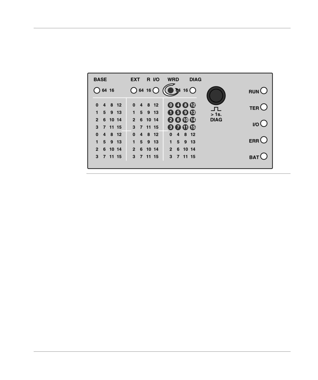
When this bit is at 1, the first 16 LEDs in the first display panel are lit.
172
TSX DM 37 xxE

Display of language objects
Index word : %SW68
Word objects
Words that can be displayed are handled in the form of a table (16 words max. with
(%MWi, %SWi
the same table), of which the first object has a 0 index and the last one the last
and KWi)
maximum index (15 max.). In hexadecimal display, the current index is the index of
the only word being displayed.
Supposing, for example, that a table has 8 internal words from %MW12 to %MW19.
The current index can take a value from 0 to 7, which determines the word displayed:
0 displays the content of the word %MW12, 1 displays that of %MW13, etc. and 7
that of %MW19.
In binary display, the current index is that of the first 4 words displayed (word
displayed by the first 16 LEDs in the first display panel).
Supposing, for example, that the same table has 8 internal words from %MW12 to
%MW19.
The current index can take a value from 0 to 7, which determines the 4 consecutive
words displayed:
Current index
Words displayed
0
%MW12, %MW13, %MW14 and %MW15
1
%MW13, %MW14, %MW15 and %MW16
2
%MW14, %MW15, %MW16 and %MW17
3
%MW15, %MW16, %MW17 and %MW18
4
%MW16, %MW17, %MW18 and %MW19
5
%MW17, %MW18, %MW19 and %MW12
6
%MW18, %MW19, %MW12 and %MW13
7
%MW19, %MW12, %MW13 and %MW14
TSX DM 37 xxE
173
Display of language objects
Bit objects (%Mi, the bits are always displayed in groups of 64, therefore the maximum index is not
%Si and %Xi)
used for these types of objects. The current index indicates the group number during
display.
bit table and corresponding index:
Bits
Index
For the 256 internal
current index 0 corresponds to %M0 to %M63 bits,
bits %Mi
current index 1 corresponds to %M64 to %M127 bits,
current index 2 corresponds to %M128 to %M191 bits,
current index 3 corresponds to %M192 to %M255 bits,
For the 128 system
current index 0 corresponds to %S0 to %S63 bits,
bits %Si
current index 1 corresponds to %S64 to %S127 bits,
For the 128 Grafcet
current index 0 corresponds to %X0 to %X63 bits,
step bits (96 for the
current index 1 corresponds to the %X64 to %X127 bits (to %X95
TSX 37-10)
for the TSX 37-10)
Remote input/
The inputs/outputs of 2 consecutive TSX 07 PLCs on the offset input/output bus are
output bit
displayed in the first 2 display panels. The inputs are displayed by 16 LEDs located
objects (%I and
in the upper part of the panels and the outputs by the 16 LEDs located in the lower
%Q)
part. For these types of objects, the current index corresponds to the TSX 07 link
address, displayed in the first display panel.
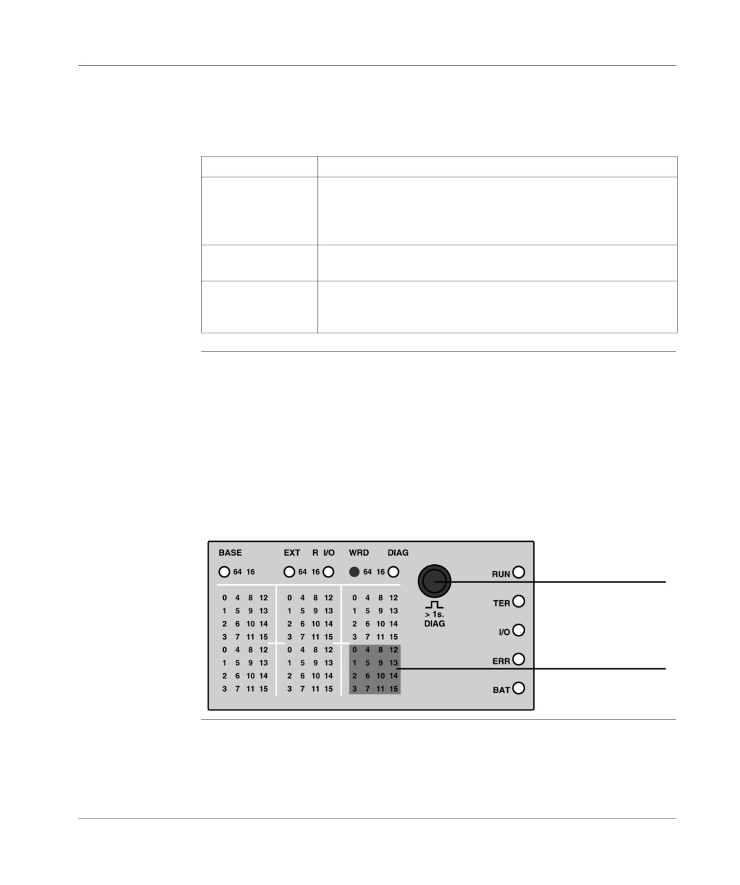
Whatever the type of displayed object, the current index is displayed by the 16 LEDs
located in the lower part of the third display panel. Each press on the push button
increases or decreases this index, according to the configured direction of
movement (bit 5 of the system word %SW67).
Illustration:
Push button
Current index
174
TSX DM 37 xxE
Display of language objects
Word %SW69
General points
Contains the number of the first word of the table, i.e. the number of the first word to
be displayed. Remember that a maximum of 16 words can be displayed, with 4
words displayed simultaneously in binary mode and one single word displayed in
hexadecimal mode. To facilitate identification of the word(s) currently being
displayed, you are advised to choose a first word, whose address is 0 or a multiple
of 10.
The first word currently being displayed is defined by the current index (see Index
word : %SW68, p. 173).
The word %SW69 is not used with bit objects.
Value of the
following a prior mode deactivation (setting %S69 bit to 0)
system words
Deactivation of WORD mode does not alter the content of the 3 system words.
%SW67 to
Upon reactivation (setting %S69 to 1), the system words %SW67 to %SW69
%SW69 upon
revert to their value at the time of the last mode deactivation. You are however
activating WORD
advised to reinitialize the current index each time you enter the mode, in order to
mode
avoid uncertainty caused by an accidental press on the push button.
after a warm start
The 3 system words revert to their value at the time of the power failure.
after a cold start
The 3 system words are initialized to the following values:
%SW67 = H’xxD0’ -> display of the internal words %MW in hexadecimal
mode, alternating between the most and least significant. Movement in the
table is performed via incrementation,
%SW68 = H’0F00’ -> display of the index word 0 and movement to index word
15, by pressing the push button,
%SW69 = H’0000’ -> the first word in the table has the number 0 (%MW0).
by default and without any special programming, it is possible to display the content
of the internal words %MW0 to %MW15.
TSX DM 37 xxE
175
Display of language objects
Example : word display in hexadecimal mode
Text display
The content of the 4 internal words %MW6 to %MW9 can be displayed in
alphanumeric hexadecimal mode. The values of these words are H’1234’, H’5678’,
H’9ABC’ and H’DEF0’, respectively.
To do this, the content of the system words %SW67 to %SW69 is as follows:
Most/ least significant alternation
Incrementation of words
Hexadecimal
%MWi
%SW67 = 0 0 000000 11 0 1 0000
Maximum index : 3 (4 words %MWi)
Current index: 0 (%MW6 displayed)
%SW68 = 00000011 00000000
First word on the table : 6
(%MW6 displayed)
%SW69 = 0000000000000110
176
TSX DM 37 xxE
Display of language objects
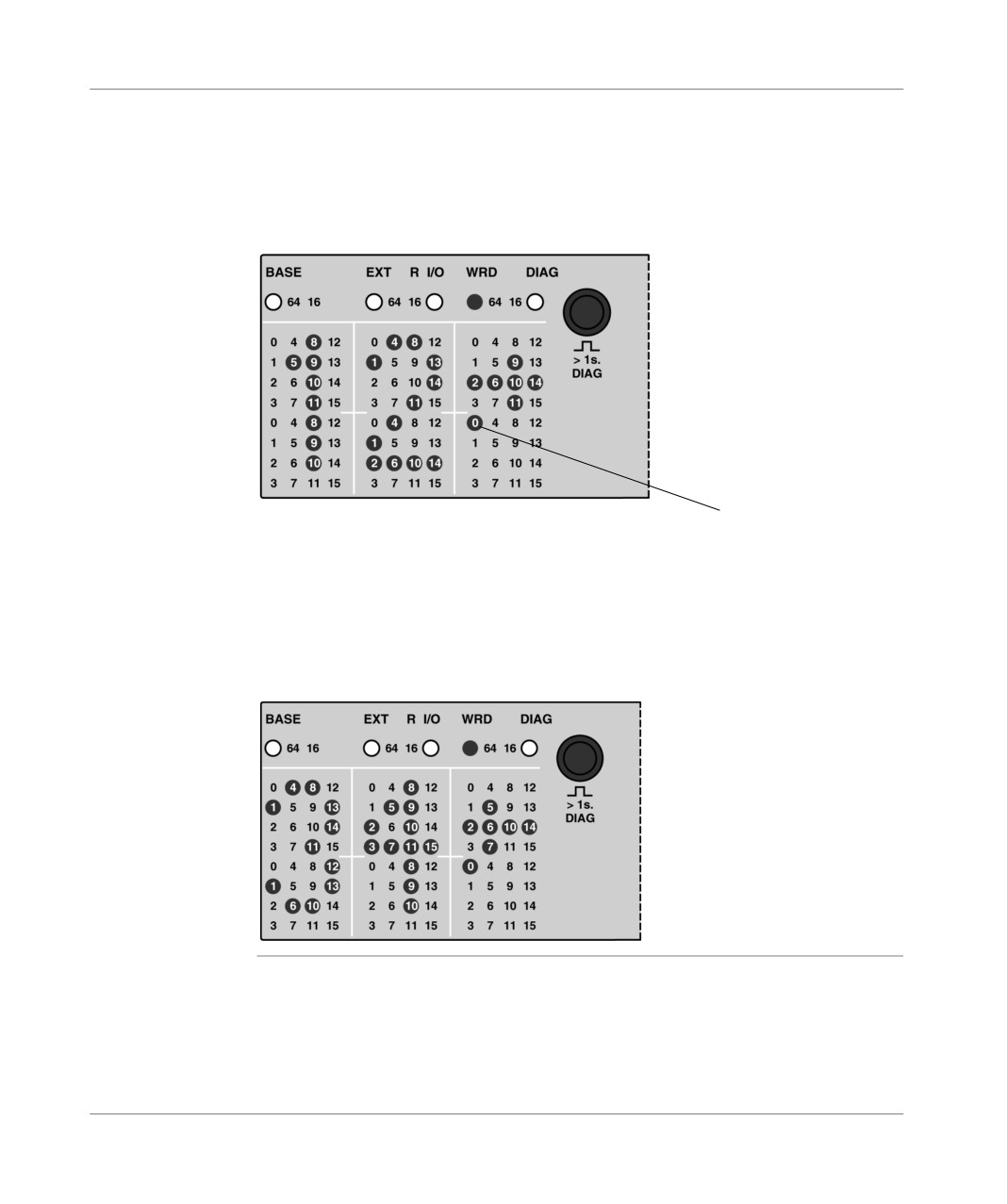
Display on the
Current index = 0, the first two panels alternately display the most/least significant
PLC
content of the first word in the table (%MW6); namely "12" and "34". The arrows ->
or <- indicate that the right part of the word (least significant) or the left part of the
word (most significant), respectively, will be displayed at the next alternation (every
2s).
Illustration:
Current index
A short press on the push button increases the current index, which becomes equal
to 1 (the 1 LED is therefore lit and the 0 LED is off). The content of the next word in
the table (%MW7) is displayed with the most and least significant alternating,
namely "56" and "78".
Successive presses on the push button will display all the words in the following
sequence: %MW6 -> %MW7 ->%MW8 ->%MW9 -> %MW6 -> etc...
Illustration:
TSX DM 37 xxE
177

Display of language objects
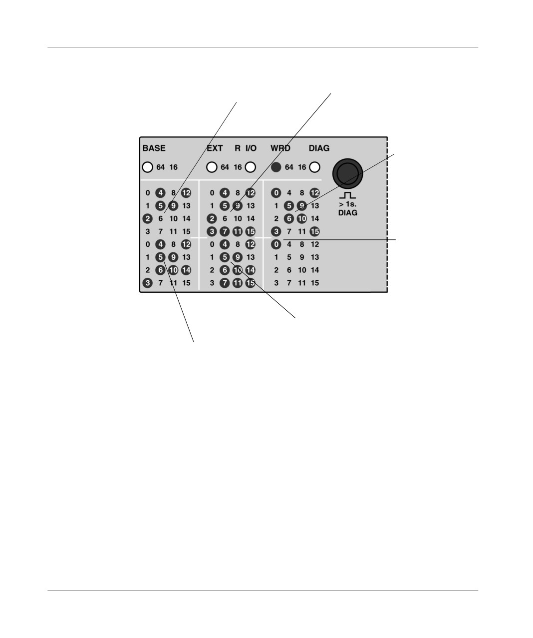
Example : word display in binary mode
Text display
The content of the 4 internal words %MW6 to %MW9 can be displayed in binary
mode. The values of these words are H’1234’, H’5678’, H’9ABC’ and H’DEF0’,
respectively.
The content of the system words is as follows:
Incrementation of words
Binary
%MWi
%SW67 = 0 0 000000 00 0 0 0000
(type of object = 0)
Maximum index : 3 (4 words %MWi)
Indice courant : 0 %MW6 displayed)
%SW68 = 00000011 00000000
First word in the table : 6 (%MW6)
%SW69 = 0000000000000110
178
TSX DM 37 xxE
Display of language objects
Display on the
Illustration:
PLC
Contents of the %MW6 word defined by
Contents of the %MW8 word :
the current index (first word in the table) :
%MW8 = 10011010101111100
%MW6 = 0001001000110100
Sign X, indicating a
binary display
Current index = 0
Contents of the %MW9 word :
%MW9 = 1101111011110000
Contents of the %MW7 word :
%MW7 = 0101011001111000
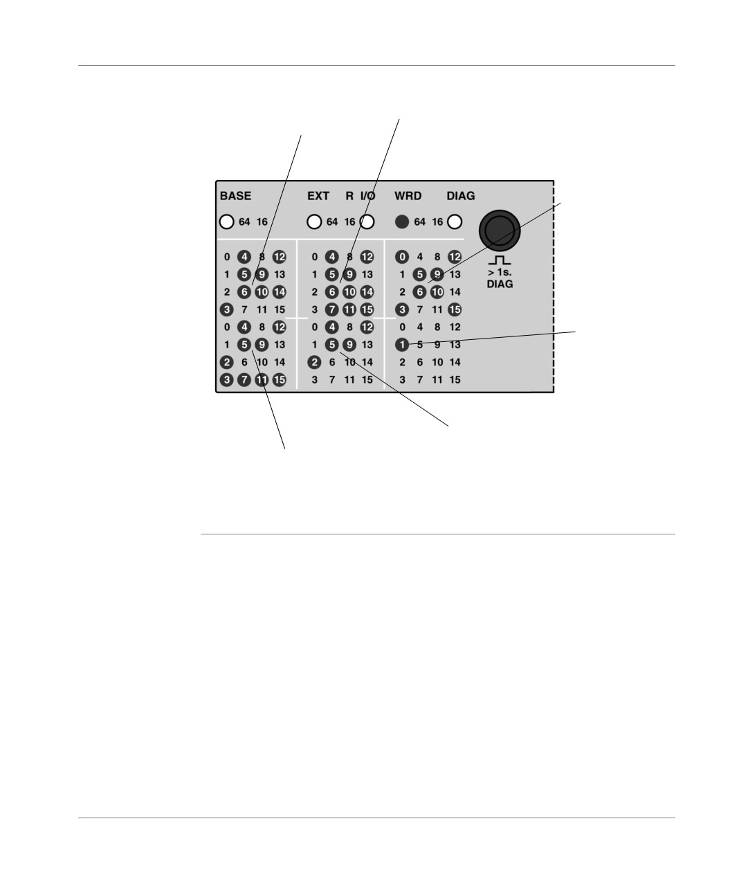
A short press on the push button increases the current index, which takes the value
1. The upper part of the first panel displays the content of the index word 1 in the
table (%MW7), the lower part of the first panel displays the content of %MW8, the
upper part of the second panel displays the content of %MW9 etc.
TSX DM 37 xxE
179
Display of language objects
Illustration:
Contents of the %MW7 word
Contents of the %MW9 word
defined by the current index
Sign X, indicating a
binary display
Current index = 1
Contents of the %MW6 word
Contents of the %MW8 word
Successive presses on the push button display all the words, by shifting a 4-word
window among the maximum possible 16 (limited to 4 in the example above). The
index of the word displayed in the upper part of the first panel is defined by the
current index (lower part of the third panel).
180
TSX DM 37 xxE
Display of language objects
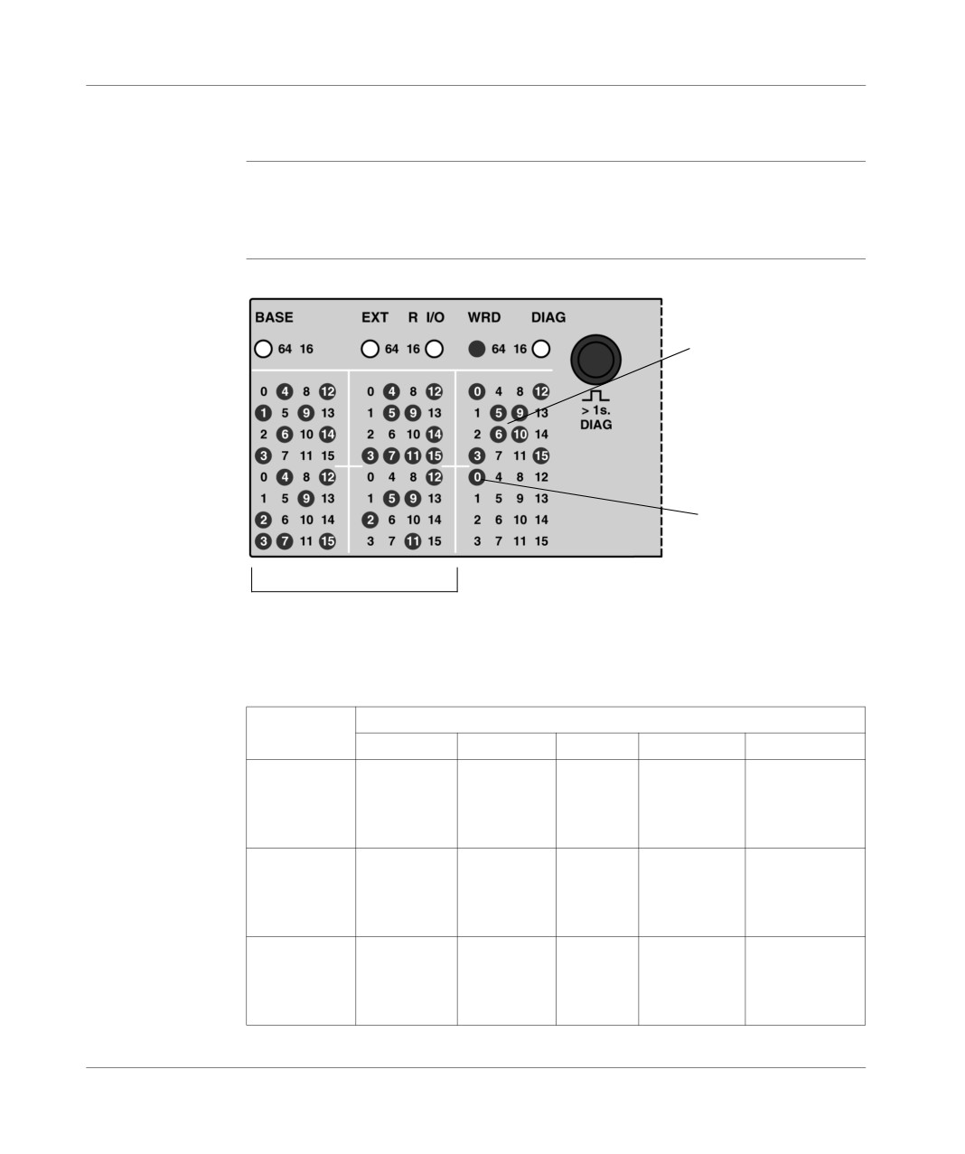
Example : display of the internal bit status
Text display
The status of the 256 internal bits in the TSX 37 PLC can be displayed (%M0 to
M255). Upon WORD mode activation and if the current index is 0, the status of the
first 64 internal bits is displayed (%M0 to M63).
Display on the
Illustration:
PLC
Sign X, indicating a
binary display
Current index = 0
State of the %M0 to %M63 bits
A short press on the push button increases the current index (value 1), which
displays the status of the next 64 internal bits (%M64 to %M127) and then from
%M192 to %M255; the current index adopts the values 0, 1, 2 and 3 successively.
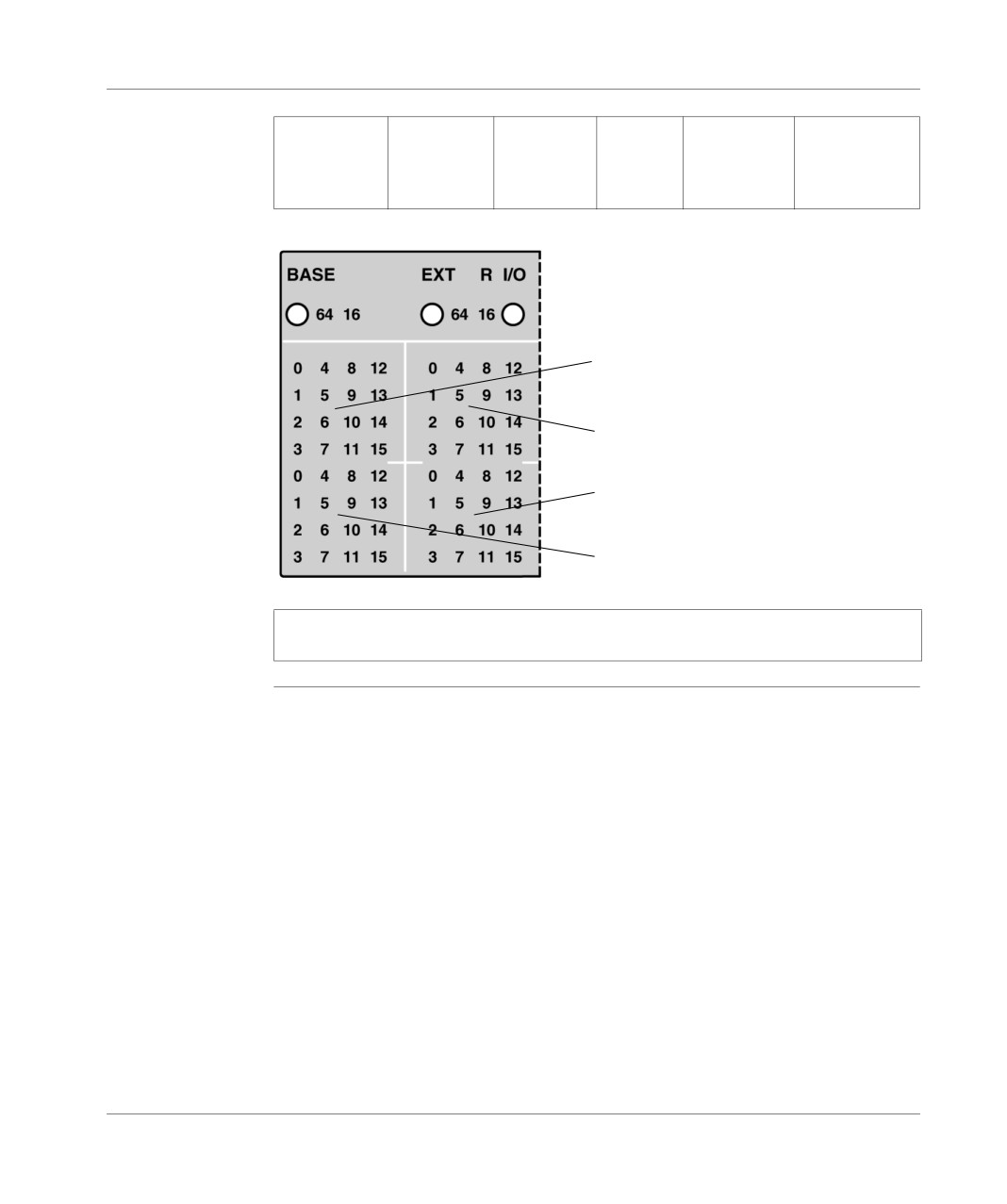
LED table:
Index
LEDs
0
1
4
8
15
0
%M0
%M1
%M4
%M8
%M15
1
%M64
%M65
%M68
%M72
%M79
2
%M128
%M129
%M132
%M136
%M143
3
a
%M192
%M193
%M196
%M200
%M207
0
%M32
%M33
%M36
%M40
%M47
1
%M96
%M97
%M100
%M104
%M111
2
%M160
%M161
%M164
%M168
%M175
3
b
%M224
%M225
%M228
%M232
%M239
0
%M48
%M49
%M52
%M56
%M63
1
%M112
%M113
%M116
%M120
%M127
2
%M176
%M177
%M180
%M184
%M191
3
c
%M240
%M241
%M244
%M248
%M255
TSX DM 37 xxE
181
Display of language objects
0
%M16
%M17
%M20
%M24
%M31
1
%M80
%M81
%M84
%M88
%M95
2
%M144
%M145
%M148
%M152
%M159
3
d
%M208
%M209
%M212
%M216
%M223
Illustration:
a
b
c
d
Note: The display of the system bits and the Grafcet step bits is identical, the
current index only adopts the value 0 or 1.
182
TSX DM 37 xxE
Display of language objects
Example: Display of remote inputs/outputs on TSX 07
Text display
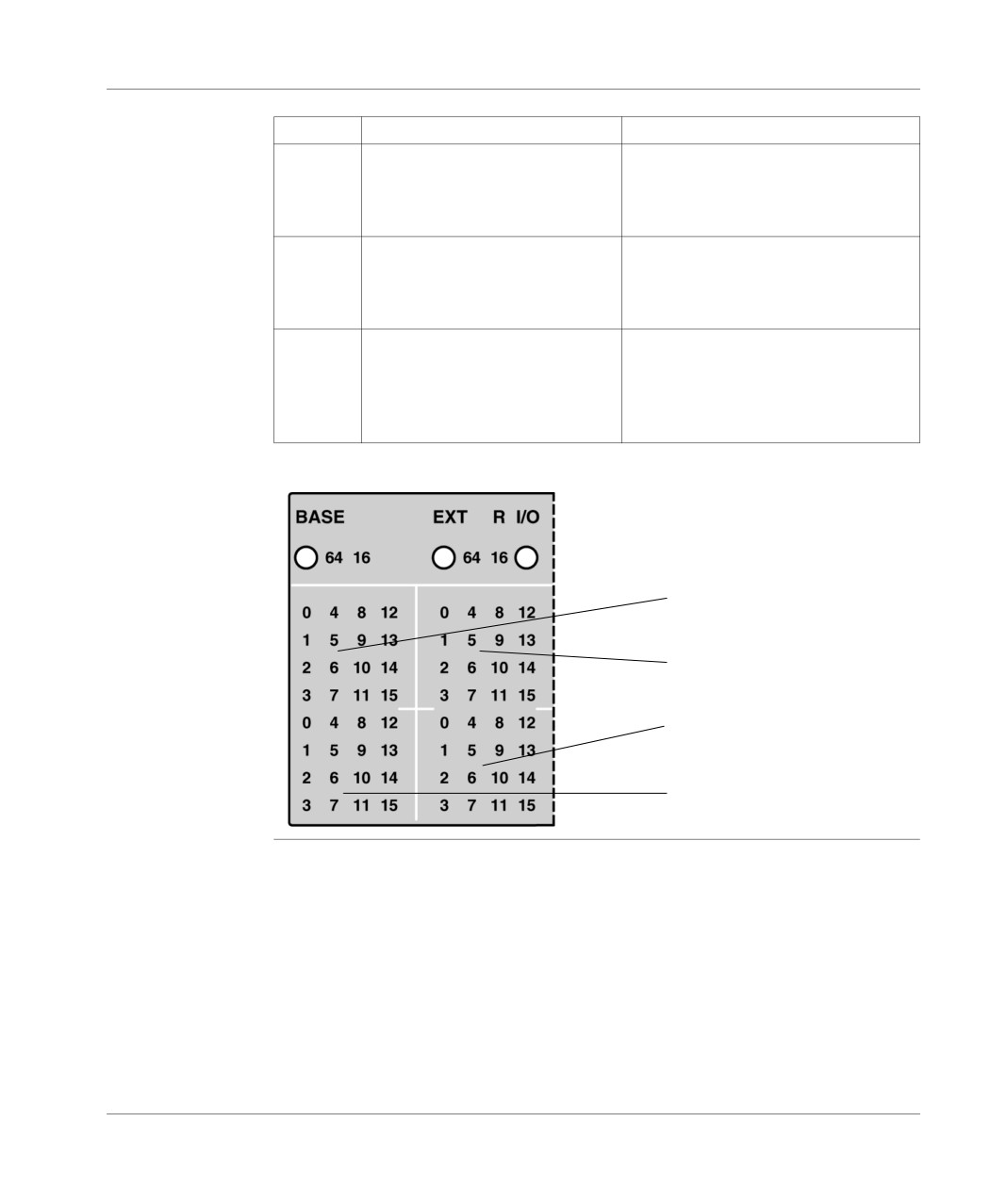
The remote 4 TSX 07 PLC inputs/outputs can be displayed, connected to the remote
input/output bus. By activating the mode and if the current index is worth 1, the first
block displays the address 1 PLC inputs/outputs and the second block displays
those of the address 2 PLC. By pressing the push button the current index is
increased, which displays in the first block the address 2 PLC inputs/outputs and in
the second block those of the address 3 PLC, etc. Continuous pressing on the push
button allow all the remote inputs/outputs to be displayed.
Display on the
Illustration:
PLC
State of the 14 PLC address 2
State of the 14 PLC address 1 inputs
inputs (first 14 LEDs)
(first 14 LEDs)
Sign X, indicating
a binary display
current index = 1
State of the 10 PLC address 2
State of the 10 PLC address 1 outputs
outputs
(first 10 LEDs)
(first 10 LEDs)
Table of inputs/outputs:
Index
TSX 07
Inputs/Outputs
1
Address 1
%I\4.0\1.0 à %I\4.0\1.13
2
Address 2
%I\4.0\2.0 à %I\4.0\2.13
3
Address 3
%I\4.0\3.0 à %I\4.0\3.13
4
a
Address 4
%I\4.0\4.0 à %I\4.0\4.13
TSX DM 37 xxE
183
Display of language objects
Index
TSX 07
Inputs/Outputs
1
Address 2
%I\4.0\2.0 à %I\4.0\2.13
2
Address 3
%I\4.0\3.0 à %I\4.0\3.13
3
Address 4
%I\4.0\4.0 à %I\4.0\4.13
4
b
Address 1
%I\4.0\1.0 à %I\4.0\1.13
1
Address 2
%I\4.0\2.0 à %I\4.0\2.9
2
Address 3
%I\4.0\3.0 à %I\4.0\3.9
3
Address 4
%I\4.0\4.0 à %I\4.0\4.9
4
c
Address 1
%I\4.0\1.0 à %I\4.0\1.9
1
Address 1
%I\4.0\1.0 à %I\4.0\1.9
2
Address 2
%I\4.0\2.0 à %I\4.0\2.9
3
Address 3
%I\4.0\3.0 à %I\4.0\3.9
4
Address 4
%I\4.0\4.0 à %I\4.0\4.9
d
Illustration:
a
b
c
d
184
TSX DM 37 xxE
Commissioning
19
At a Glance
Aim of this
This chapter is about the commissioning of the TSX 37 PLCs.
Chapter
What's in this
This Chapter contains the following Maps:
Chapter?
Topic
Page
First power-up
186
Description of PLC states
188
TSX DM 37 xxE
185
Commissioning
First power-up
Principle
When switched on, the PLC carries out its self-tests then places itself on hold for an
application transfer. The different states of the PLC are signaled at the level of the
display block by the RUN, ERR, I/O LEDs. .
186
TSX DM 37 xxE
Commissioning
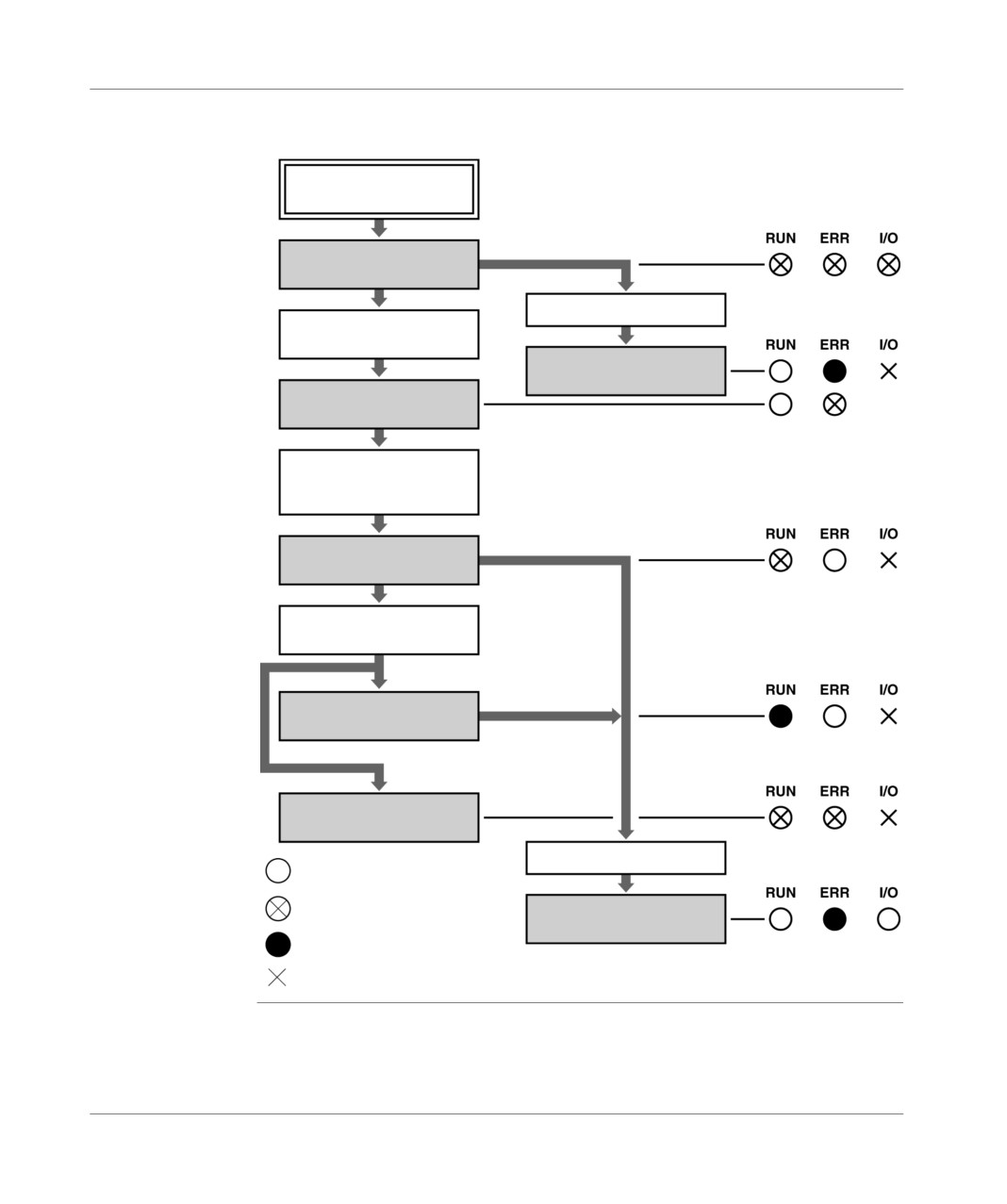
The diagram below shows the procedure that must be followed when switching on
for the first time, according to the state of the monitors:
Starting up
the PLC
PLC self tests
CPU error
No application
in the PLC
“PLC in error” state
“PLC” state
not configured”
Transferring a valid
application in the PLC
“PLC stop” state
Putting the PLC in
RUN
“PLCfunctioning”state
“PLC in software error or
HALT” state
Supply fault
LED off
LED blinking
“PLC waiting” state
LED illuminated
Not determined
TSX DM 37 xxE
187

Commissioning
Description of PLC states
General
Table of PLC states and their description:
State
Description
PLC self tests
The PLC processor carries out its sef-tests internally. The PLC
does not control the process and cannot communicate via its
terminal port (or networks).
This state is signaled by the 3 monitors RUN, ERR et I/O
blinking.
"PLC in error" state
The PLC stops following a material breakdown or an error
within the system. The process is no longer controlled,
communication becomes impossible and only a cold-start is
possible (by activating the RESET button, using the gripper,
etc.)
This state is signaled by the monitors RUN, which is switched
off and ERR, which is switched on.
"non-configured" PLC
The PLC started but does not possess any valid applications.
state.
It does not control the process but can communicate by its
terminal point (or its network). This state is signaled by the
monitors RUN, which is switched off and ERR, which flashes.
"PLC in software error or
The PLC application went to "overrun" or executed an
HALT" state
unresolved jump, a HALT instruction or a non-implemented
"floating" instruction. This state is signaled by the monitors
RUN and ERR blinking.
"PLC stop" state
The PLC possesses a valid application, which is stationary (the
application is in a initial state, the tasks are stopped at the end
of the cycle) and the commands of the process are in a state of
fallback. This state is signaled by the RUN monitor blinking.
"PLC functioning" state
The PLC application runs as normal in order to control the
process. A non-blocking fault for the application (input/output
error or software error) can also exist. This state is signaled by
the monitor RUN, which is switched on (and the I/O module is
switched on if there are input/output errors).
"PLC waiting" state
The PLC has detected a supply failure. It is in a backup state
while waiting for the supply to return (attempt at restarting
warm). The process is no longer controlled and communication
is possible. As long as the supply allows it, this status is
signaled by the RUN monitor, which is off and the ERR monitor,
which is on.
188
TSX DM 37 xxE
Commissioning
Note: When the PLC is in the "non-configured" state (without valid application), it
is possible to carry out a discrete input/output wiring test. To do this, put the bit
system %S8 to 0 and exploit the image memory (in read and/or write) from an
adjustment terminal.
The TSX DMZ 64 DTK modules can only be used for the first 16 inputs and the first
16 outputs.
TSX DM 37 xxE
189
Commissioning
190
TSX DM 37 xxE
Maintenance
20
At a Glance
Aim of this
This chapter is about researching and analyzing the errors.
Chapter
What's in this
This Chapter contains the following Maps:
Chapter?
Topic
Page
Researching the errors from PLC status monitors.
192
Non-blocking faults
193
Blocking faults
195
Central processing unit (CPU) faults
197
Updating the Operating System
198
TSX DM 37 xxE
191
Maintenance
Researching the errors from PLC status monitors.
General
The status monitors in the display block inform the user on the operating mode of
the PLC but also on its possible faults. The errors detected by the PLC concern:
the PLC component circuits and/or its modules: internal errors,
the process controlled by the PLC or the process wiring: external errors,
the operating of the application carried out by the PLC: internal or external errors.
Errors are detected at start-up (self-tests) or during operation; as is the case with the
majority of hardware errors, during the exchanges with the modules or during the
execution of an instruction program. With certain "serious" errors, the PLC must be
restarted; others are the responsibility of the user who decides on the course of
action according to the desired application level.
There are three types of error:
non-blocking errors,
blocking errors
and central unit errors.
192
TSX DM 37 xxE
Maintenance
Non-blocking faults
Anomaly caused
The anomaly can be processed by the user program and does not modify the state
by an input/
of the PLC.
output error or
This type of anomaly is signaled by:
by the execution
the I/O status LED,
of an instruction
the LEDs of channels accessible in diagnostics mode (See Display of remote
inputs/outputs on the AS-i bus, p. 161),
the error bits and words associated with the module and channel: %Ix.MOD.ERR,
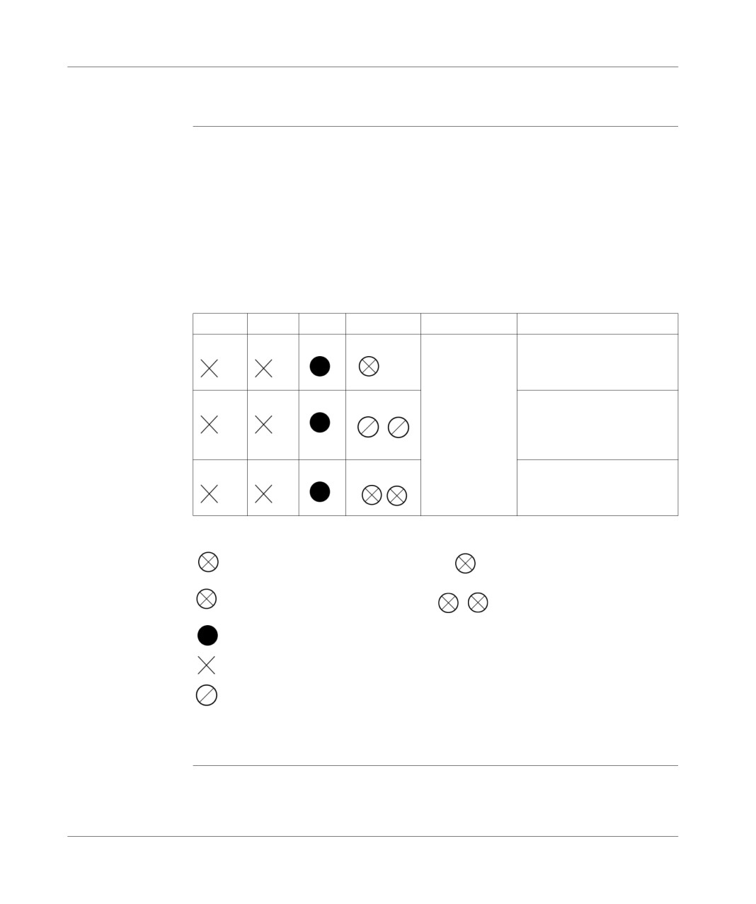
%IX.i.ERR, %MWx.MOD.2, etc.
the system bits %S10 and %S16 (see reference manual, volume 3).
LED status table:
RUN
ERR
I/O
DIAG
System bits
Faults
%S10
Channel supply fault.
%S16
Tripped channel.
Module missing.
Module does not conform to
the configuration.
Module failure (*)
Module supply fault.
Legend:
LED off
DIAG: channel LED
LED blinking rapidly
DIAG: all the module LEDs
LED on
State not
determined
LED blinking slowly
(*) While operating a PLC with a VL < 2.0 rating, any modification to the physical
configuration, which must be made when the power is off, needs a cold start to
be carried out by pressing the RESET button after power up in order to take effect.
TSX DM 37 xxE
193
Maintenance
Anomaly caused
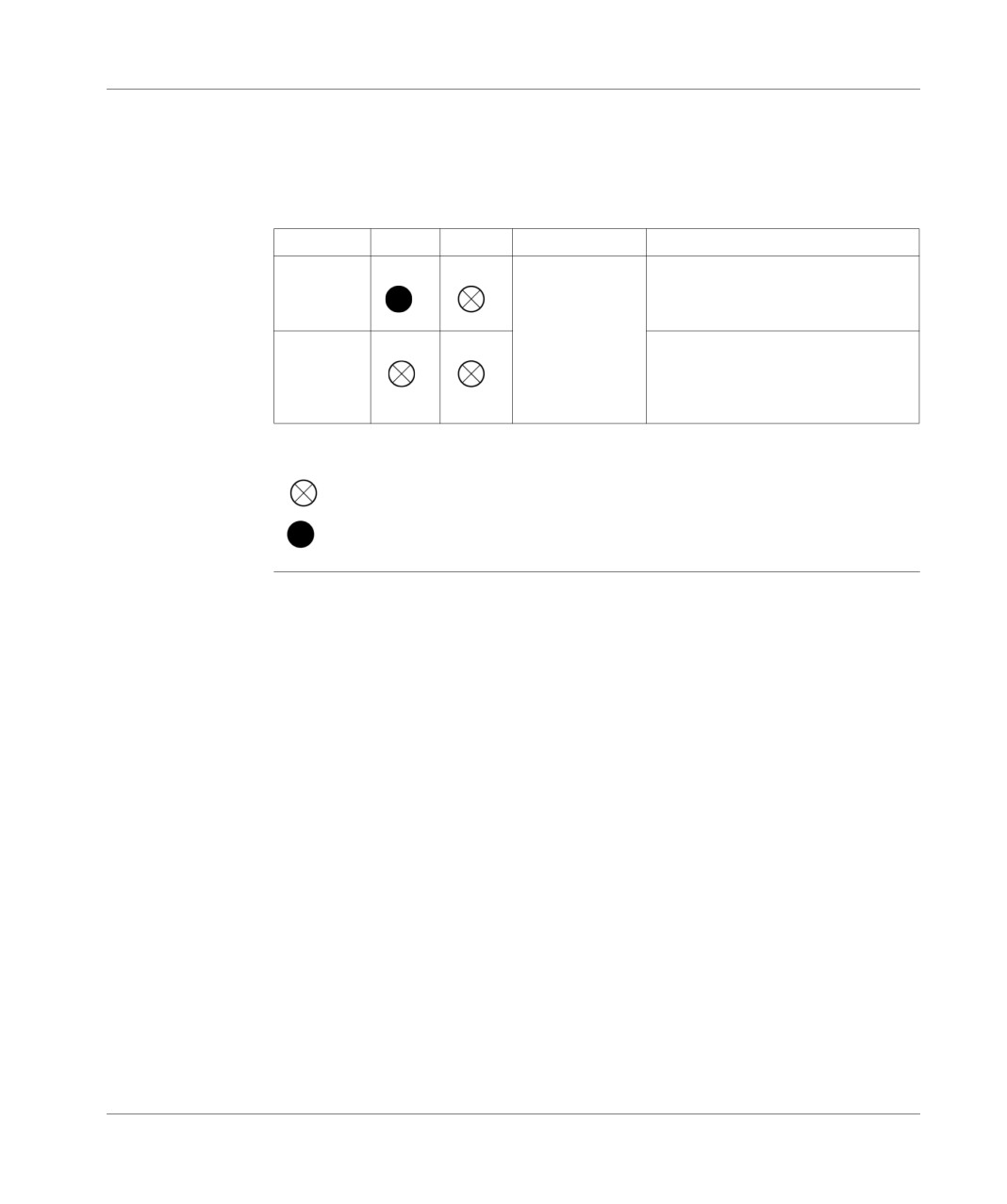
When an application is stored on the PLC, a PCMCIA card backup battery error is
by a faulty RAM-
indicated by:
type PCMCIA
the ERR LED blinking, and the RUN LED lighting up if the PLC is in RUN mode,
memory card
the ERR and RUN LEDs blinking simultaneously if the PLC is in stop mode.
backup battery
LED status table:
PLC state
RUN
ERR
System bits
Faults
RUN
%SW67 = 1
PCMCIA RAM backup battery error
with PLC in RUN
STOP
PCMCIA RAM backup battery error
with PLC in RUN.
The RUN and ERR LEDs blink
simultaneously.
Legend
LED blinking rapidly
LED on
194
TSX DM 37 xxE
Maintenance
Blocking faults
General points
These faults, caused by the application program, make it impossible to continue
execution but do not lead to a system fault. If such a fault occurs, the application
stops immediately (all tasks on the current instruction are stopped). There are two
possibilities for restarting the application:
with INIT or by setting the %S0 bit to 1. The application is thus in a preliminary
state: the data have their initial values, the tasks are stopped at the end of the
cycle, the view of the inputs is refreshed and the outputs are placed into a fallback
position,
by STOP, which brings the tasks to the end of the cycle without reinitializing the
data, then by RUN, which makes a restart possible.
TSX DM 37 xxE
195
Maintenance
Indicating a
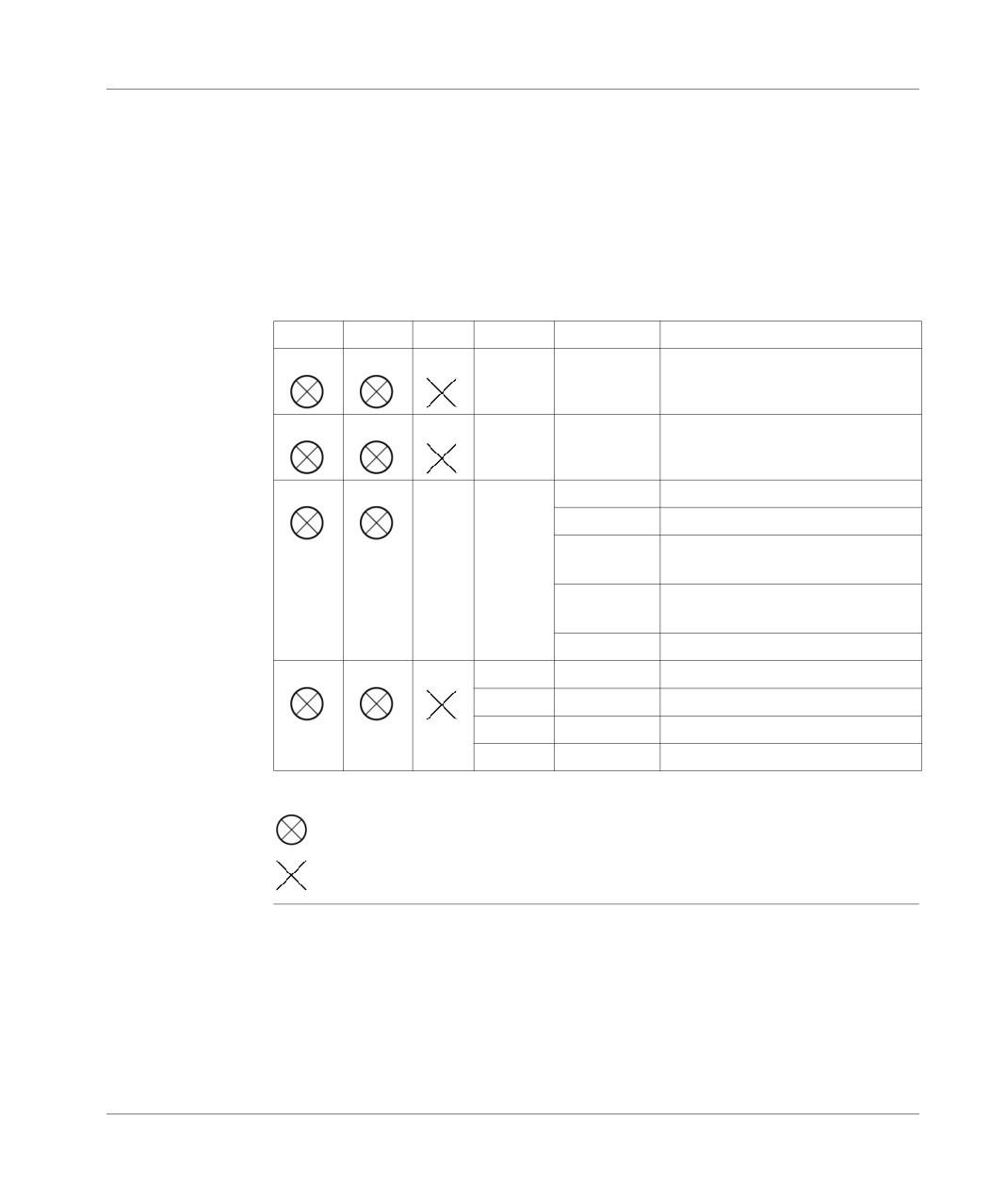
A blocking fault is indicated by:
blocking fault
the status LEDs (ERR and RUN),
the system bits %S15 to %S20 (the system bits %S15, %S18 and %S20 are only
blocking in application monitoring mode),
the system word %SW125 containing the cause of the fault,
the diagnostics program tool of the PL7 Micro which clearly communicates the
cause and origin of the switch to fault status: watchdog overrun, division by zero,
index overflow, etc.
LED status table:
RUN
ERR
I/O
Bits
%SW125
Faults
%S11
H’DEB0’
Watchdog overrun.
H’2258’
Execution of the HALT instruction.
H’DEF8’
Execution of an unresolved JUMP.
H’2xxx’
Execution of an unknown NPCALL.
H’0xxx’
Execution of an unknown primitive
OF/IOB.
H’DEF7’
Grafcet fault: step not programmed
or active step table overrun.
H’DEFF’
Non-implemented floating point.
%S18
H’DEFo’
Division by zero.
%S15
H’DEF1’
Character string manipulation error.
%S18
H’DEF2’
Capacity overflow.
%S20
H’DEF3’
Index overflow.
Legend:
LED flashing
State not
determined
196
TSX DM 37 xxE
Maintenance
Central processing unit (CPU) faults
General points
These severe faults (hardware or software) mean that correct system operation can
no longer be guaranteed. They lead to a stop in the PLC, and require a cold start.
Where possible, the fault type is memorized in the %SW124 system word; this can
be reread after the cold start.
The next cold start is forced to stop to prevent a PLC error from recurring.
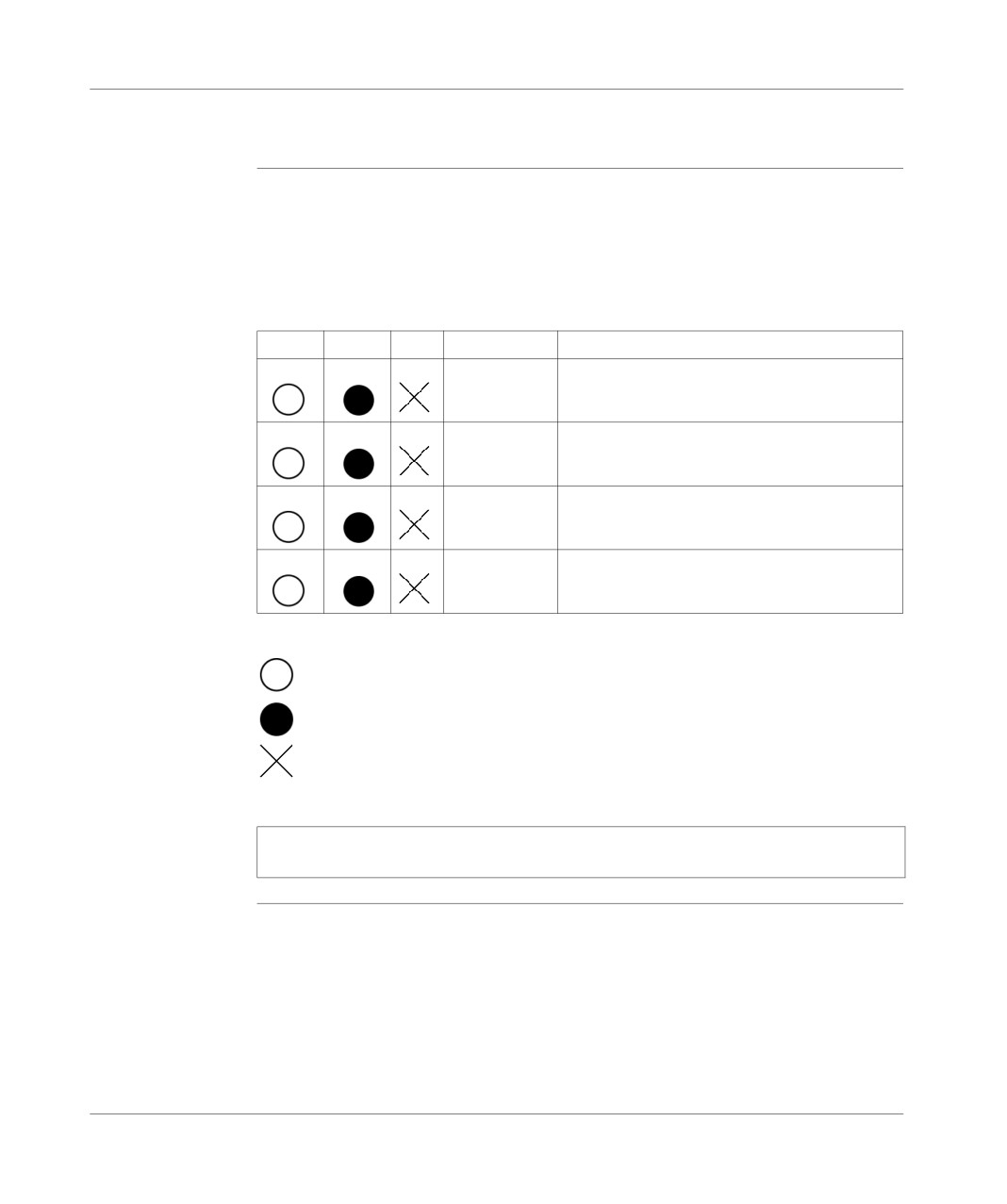
LED status table:
RUN
ERR
I/O
%SW124
Faults
H’30’
System code fault.
H’60’ to H’64’
Stack overflow.
H’90’
Interruption system fault: Unforeseen IT.
H’53’
Time-out fault during I/O exchange.
Legend:
LED off
LED on
State not
determined
Note: All LEDs (RUN, TER, I/O, ERR) are lit if the handle is missing on a TSX 37
2•.
TSX DM 37 xxE
197
Maintenance
Updating the Operating System
At a Glance
The operating system of the TSX Micro PLCs can be updated by a download via the
terminal port.
Note: The updating procedure for the operating system is described in the on-line
help associated with the PL7 software.
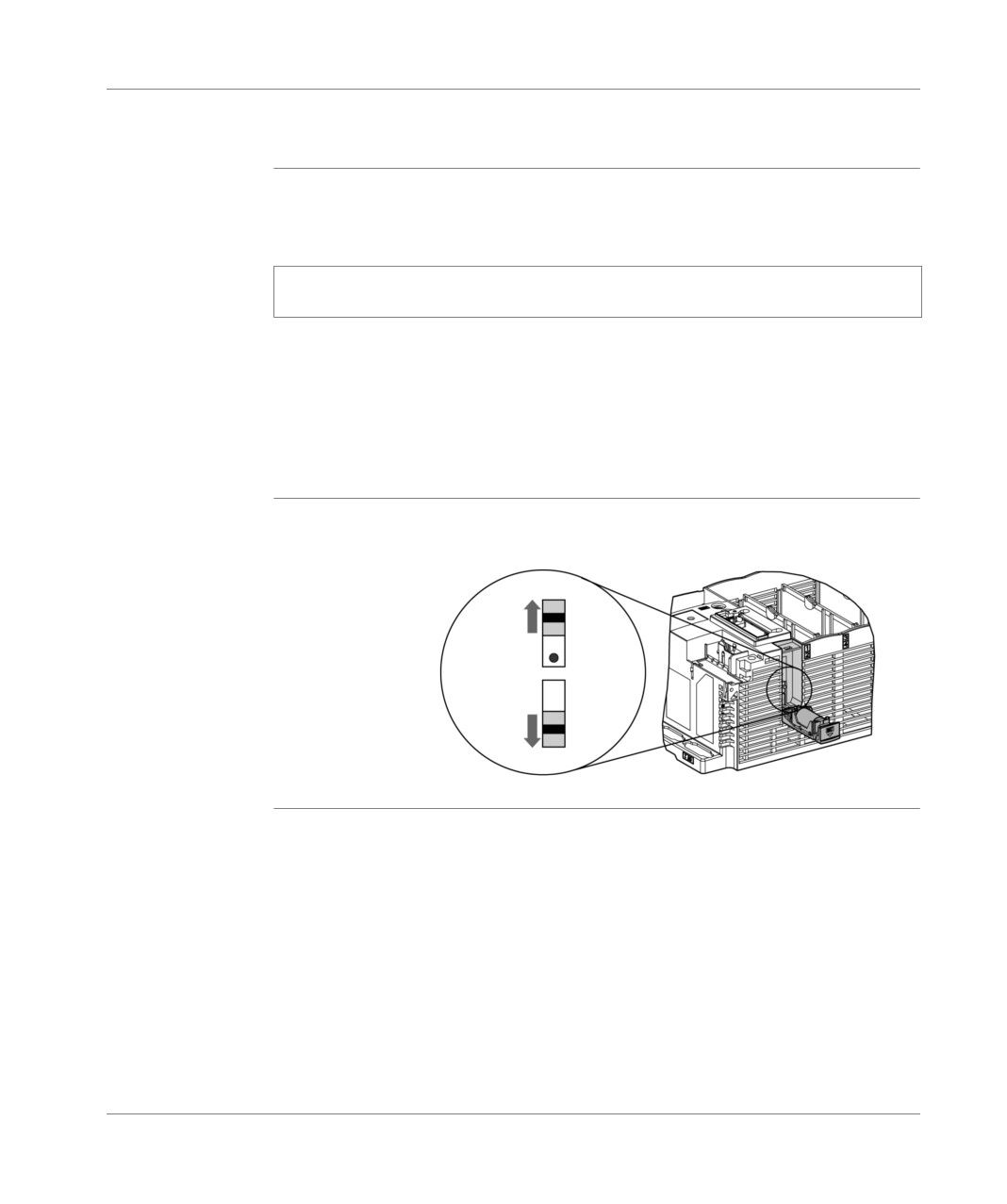
A write-protection switch located in the backup battery access hatch provides
protection for accessing the loading of the OS.
When the PLC is operating normally, this switch must be in the (OS protected)
position.
Any non-compliance with this notice, whilst not affecting the operation of the PLC,
will nevertheless cause PRG characters to flash on the central display.
Illustration
The following illustration shows the position of the write-protection switch.
OS
protected
Protection
switch
Write
authorized
198
TSX DM 37 xxE
Maintenance
Updating the OS The tool OS LOADER, provided with PL7, acts as a guide for the user during the
update phase, indicating in particular that:
the write-protection switch must be in the write authorized position in order to be
able to begin downloading the OS,
the write-protection switch must be in the OS protected position once the OS has
finished downloading.
Note: If the OS is updated with the tool OS-LOADER V1.5, you must be sure to put
the protection switch in the "write authorized" position before starting the download,
as this version of the tool does not guide the user through the entire update phase.
Likewise, once loading is complete, the switch must be put in the "OS protected"
position.
TSX DM 37 xxE
199
Maintenance
200
TSX DM 37 xxE

Analog incorporated in the bases
V
At a Glance
Aim of this tab
This tab deals with the analog interface which is built into the TSX PLC
What's in this
This Part contains the following Chapters:
part?
Chapter
Chaptername
Page
21
Overview of the built-in analog interface
203
22
Connecting the built in interface
209
23
TSX ACZ 03 adjustment and adaptation module
219
TSX DM 37 xxE
201
Analog incorporated in the bases
202
TSX DM 37 xxE