TSX Micro PLCs TSX 3705/3708/3710/3720. Implementation Manual (Volume 1) - page 4
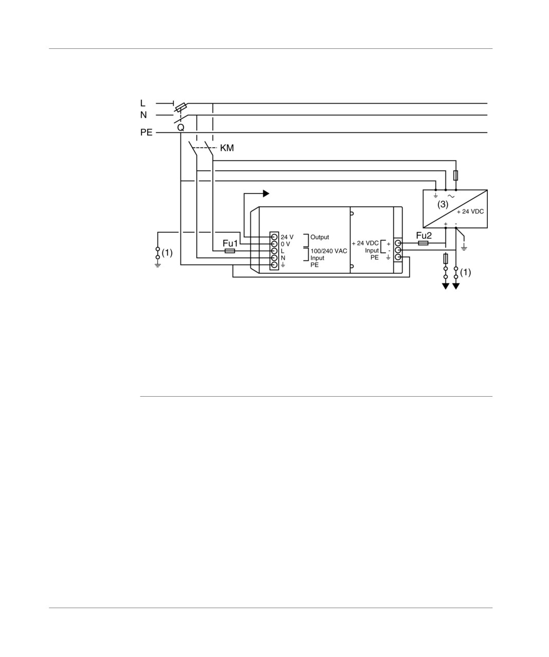
Connection
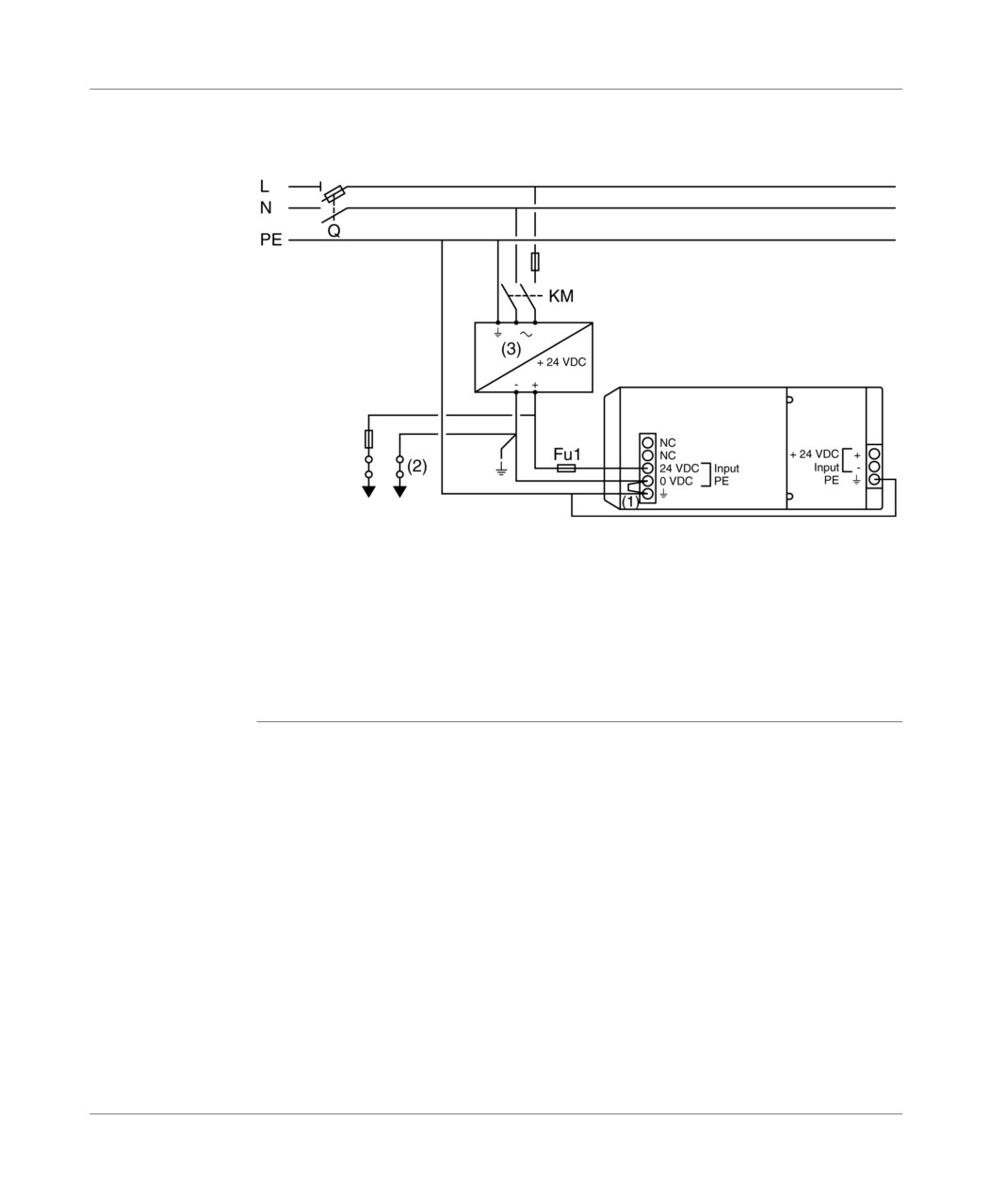
Connecting a
Illustration:
PLC with an
extension
Alternating network 100-240 V
Sensor supply
base+extension (2)
PLC
Extended
Supply for sensors/
pre-actuators
Q: general isolator, KM: line contactor or circuit breaker,
Fu1: 1 A fuse with time delay, Fu2: standard 0.5 A fuse,
(1) : isolation strip for finding grounding faults,
(2) : do not exceed 400 mA,
(3) : only if the discrete relay or analog modules are fitted in the extension.
if a TBX SUP 10 or TSX SUP 1011 supply is used, remove Fu2.
TSX DM 37 xxE
123
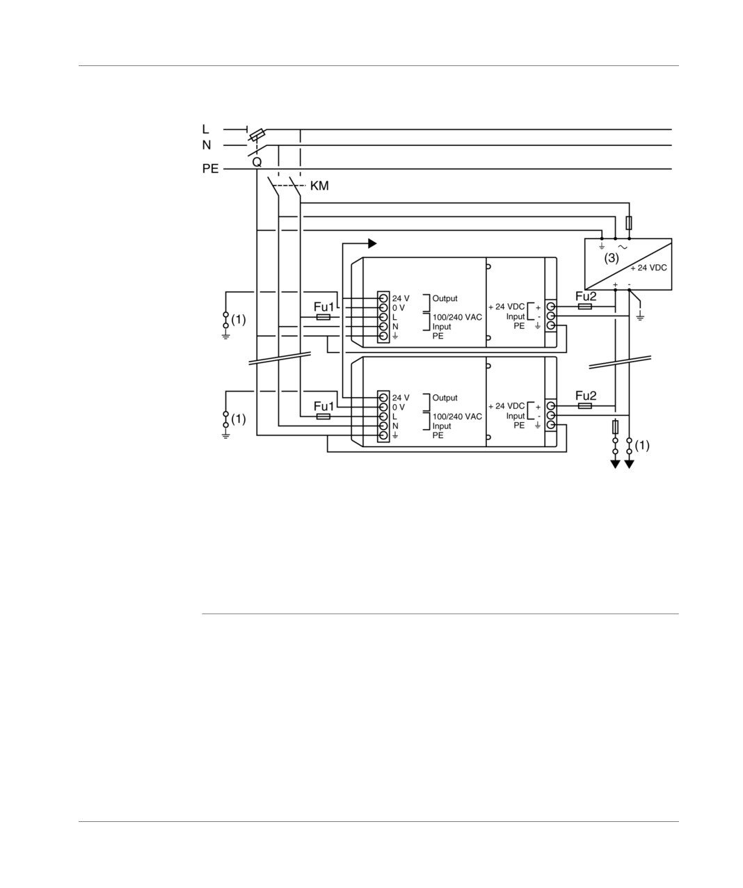
Connection
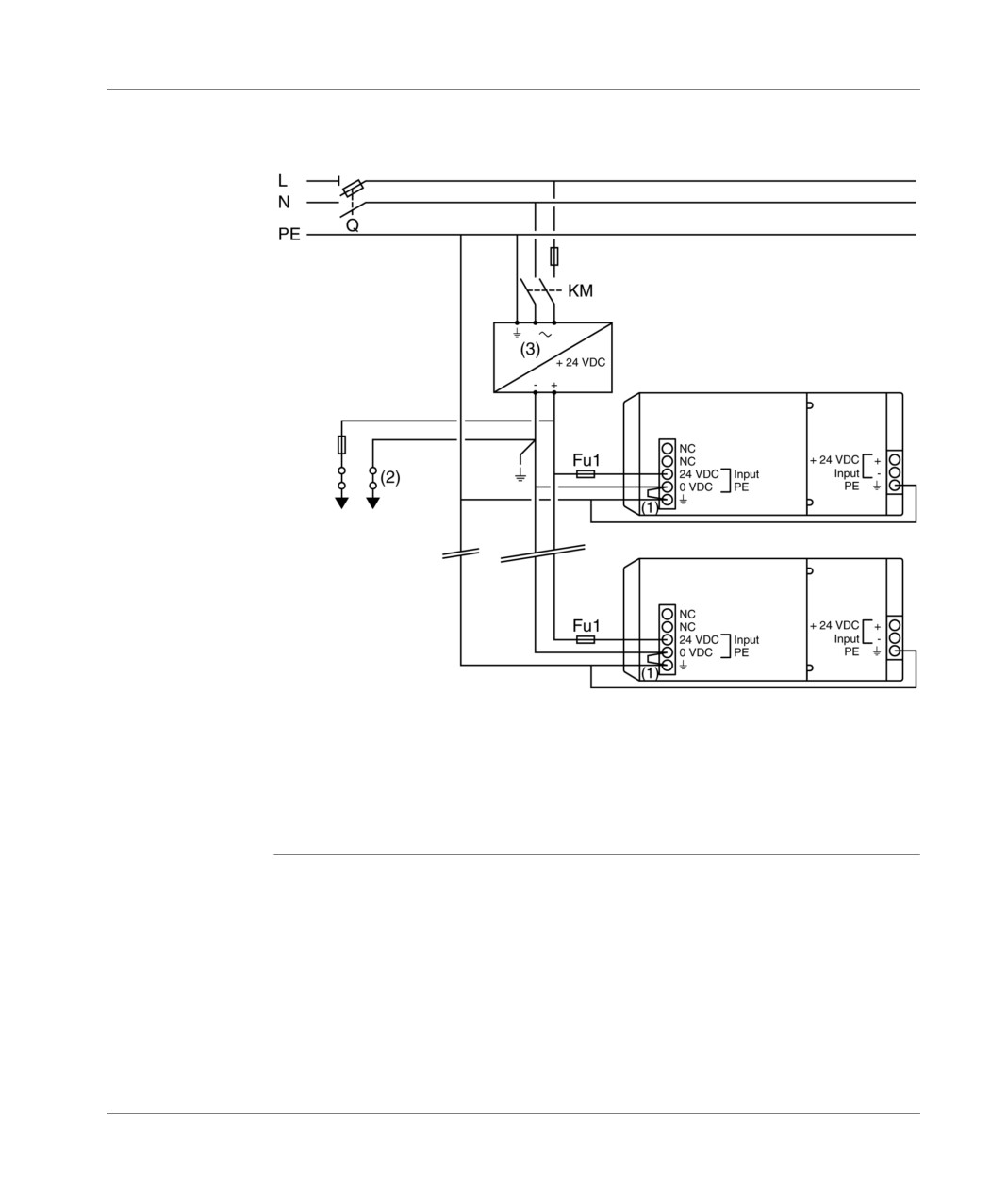
Connecting
Illustration:
several PLCs
Alternating network 100-240 V
Sensor supply
base+extension (2)
PLC
Extended
PLC
Extended
Supply for sensors/
pre-actuators
Q: general isolator, KM: line contactor or circuit breaker,
Fu1: 1 A fuse with time delay, Fu2: standard 0.5 A fuse,
(1) : isolation strip for finding grounding faults,
(2) : do not exceed 400 mA,
(3) : only if the discrete relay or analog modules are fitted in the extension.
if a TBX SUP 10 or TSX SUP 1011 supply is used, remove Fu2.
124
TSX DM 37 xxE
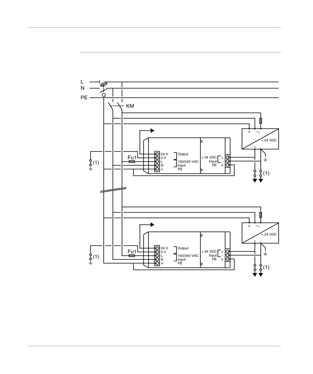
Connection
Connecting several PLCs supplied by TBX SUP 10 or TSX SUP supplies
Principle
Illustration:
diagram
100-240 V alternating network
sensor supply
base + extension (2)
Sensor/pre-actuator
supply
sensor supply
base + extension (2)
Sensor/pre-actuator
supply
Q : general sectionner.
KM : circuit breaker or line switch.
Fu1 : 1 A fuse with time delay.
(1) : isolating blade to search for an grounding error.
(2) : do not exceed 400 mA.
(3) : only if the discrete relay or analog modules are implanted in the extension.
TSX DM 37 xxE
125
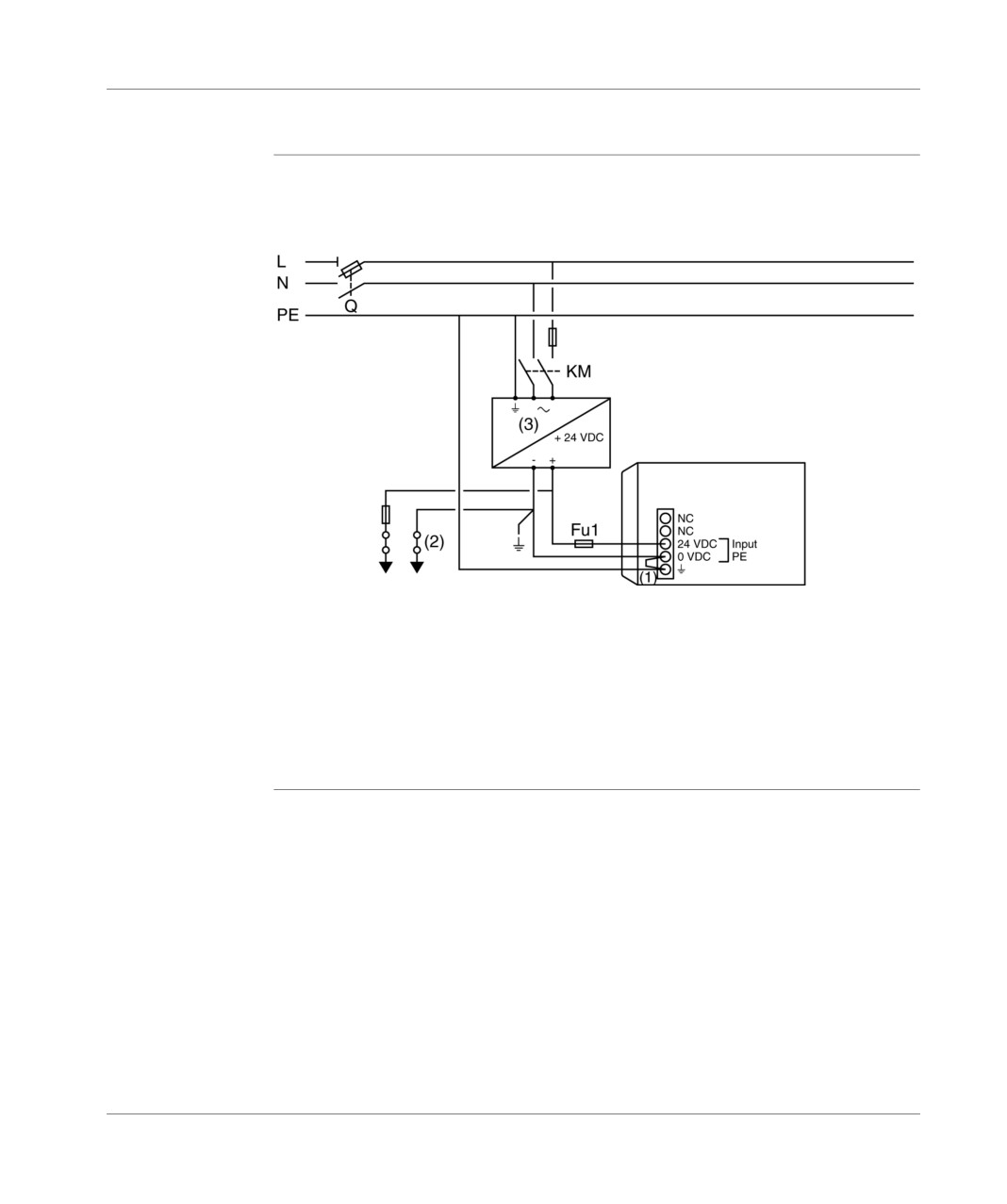
Connection
Connecting PLCs supplied with direct current
Connecting a
Illustration:
single PLC
Alternating network 100-240 V
PLC
Sensor/pre-actuator
supply
Q: general isolator, KM: line contactor or circuit breaker,
Fu1: 4A fuse with time delay,
(1) : external shunt supplied and mounted on the PLC. Should not be removed,
(2) : isolation strip for finding grounding faults. The external shunt must be removed
in order to do this, so that the supply terminal block can be disconnected from the
grounded PLC.
(3) : using a TSX SUP supply.
126
TSX DM 37 xxE
Connection
Connecting a
Illustration:
PLC with an
Alternating network 100-240 V
extension
PLC
Extended
Sensor/pre-actuator
supply
Q: general isolator, KM: line contactor or circuit breaker,
Fu1: 4A fuse with time delay,
(1) : external shunt supplied and mounted on the PLC. Should not be removed,
(2) : isolation strip for finding grounding faults. The external shunt must be removed
in order to do this, so that the supply terminal block can be disconnected from the
grounded PLC.
(3) : using a TSX SUP supply.
TSX DM 37 xxE
127
Connection
Connecting
Illustration:
several PLCs
Alternating network 100-240 V
PLC
Extended
Sensor/pre-actuator
supply
PLC
Extended
Q: general isolator, KM: line contactor or circuit breaker,
Fu1: 4A fuse with time delay,
(1) : external shunt supplied and mounted on the PLC. Should not be removed,
(2) : isolation strip for finding grounding faults. The external shunt must be removed
in order to do this, so that the supply terminal block can be disconnected from the
grounded PLC.
(3) : using a TSX SUP supply.
128
TSX DM 37 xxE
Connection
Connecting PLC(s) supplied by a continuous floating network (not grounded)
General
The TSX 37 PLCs with a 24 VDC network supply do not have primary/secondary
insulation and the internal 0V is coupled with the mechanical ground connection of
the PLC. This results in the 0V of the 24VDC network being coupled with the same
mechanical ground connection and the particular provisions to be taken for the
specific applications and in particular Applications in a marine environment,
which use a "floating" mount.
The only correct way of connecting a TSX 37 (1) PLC to this type of "floating"
network is to place an insulated continuous converter (24 VDC/24 VDC) near each
PLC, and use an insulation controller upstream of the converter(s). With this type of
mounting, the first insulation error (i.e. a wire leading one of the floating network
polarities to the ground connection) is detected by the insulation controller and does
not produce any error affecting the automatic operation.
(1) TSX 37 10 PLC: TSX 3710 128DR1/128DT1/128DTK1/164DTK1
TSX 3721/22 PLC: TSX 3721 1../ TSX 3722 1..
TSX DM 37 xxE
129
Connection
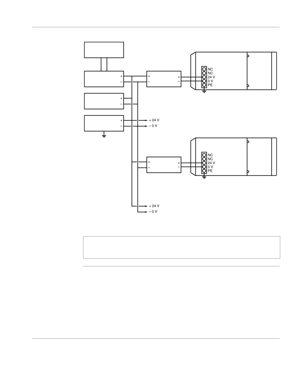
Principle
Illustration:
diagram
Alternating
network
low voltage
PLC 1 (1)
Extension
Converter
Battery
DC/DC
charger
remote
Battery
24 VCC floating network to supply the
Insulation
sensors, actuators and input/output modules
controller
PLC 2 (1)
Extension
Converter
DC/DC
remote
24 VCC floating network to supply the
sensors, actuators and input/output modules
(1) TSX 37 10 PLC: TSX 3710 128DR1/128DT1/128DTK1/164DTK1
TSX 3721/22 PLC: TSX 3721 1../ TSX 3722 1..
Note: The DC/DC converter should be very close to the PLC 2 and the + 24 VDC
polarity wire should be connected in such a way that it cannot accidentally lead to
the ground connection.
130
TSX DM 37 xxE
Connection
Specific provisions for a continuous floating network
Discrete inputs/
The Discrete inputs/outputs are insulated, the sensor, actuator and discrete input/
outputs
output module supply should come directly from the floating 24 VDC network.
Counting inputs,
These inputs are insulated; the supply and that of the input’s related sensors should
built in to the
come from the floating 24 VDC network.
TSX 37 22 1.. PLC
bases.
Analog inputs/
These inputs/outputs are not insulated (0V grounded), and should not be used
outputs, built in
with this type or mounting.
to the TSX 37 22
1.. PLC bases.
In cases where analog inputs/outputs are required, only use analog input/output
modules (TSX AEZetc./ASZetc.), which are insulated. The sensor supply related to
analog inputs should come from the floating 24 VDC network, with the outputs
delivering a voltage and a current insulated from the ground connection.
Module with
If the modules with relay outputs are built into the PLC, the DC/DC converter should
relay outputs
deliver a voltage of 24 VDC +/- 10%.
PLC with a mini
If the PLC has a mini extension rack, the mini extension rack is not supplied with 24
extension rack
VDC.
Communication
Communication links between PLCs: No specific provision.
between PLCs
communication via terminal port: insulation is performed by the TSX P ACC01
unit,
communication via PCMCIA card: the PCMCIA communication card ensures
insulation.
TSX DM 37 xxE
131
Connection
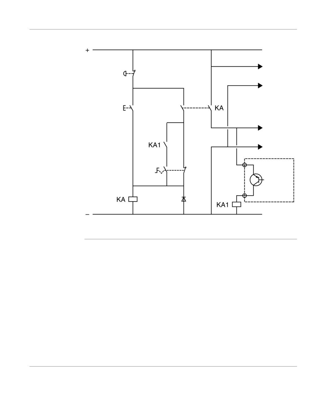
Sensor and pre actuator supply control
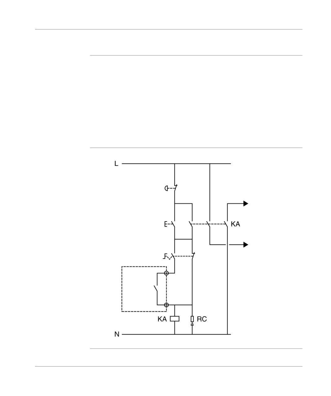
General
It is advised to control the different supplies with the following sequence:
Power up PLC and inputs (sensors) supply with the KM contactor.
If the PLC is in RUN and AUTO mode, power up output (pre-actuators) supply
with the KA connector. This is performed via the ALARME (%Q2.0) output, which
will be relayed (to KA1) if the output is static (continuous supply).
Furthermore, the safety standards require authorization from the operations
personnel, before the installation is rebooted following a stop (arising from a power
outage or from an emergency stop). The following control diagrams take into
account these standards.
The MANU/AUTO switch forces the outputs from a terminal, when the PLC is in
STOP mode.
PLC supplied
Illustration:
with alternating
current
Emergency
stop
Supply
Start
pre-actuators
AUTO
Exit
ALARM
KA : Control contactor controlled by the ALARM (Q2.0) output in AUTO mode.
132
TSX DM 37 xxE
Connection
PLC supplied
Illustration:
with direct
current
Emergency
Supply
stop
sensors
Start
Supply
pre-actuators
AUTO
MAN
Exit
ALARM
KA : contactor controlled at the ALARM (Q2.0) output by the KA1 relay.
KA1 : relay at the ALARM (Q2.0) output or static (Q2.0) output.
TSX DM 37 xxE
133
Connection
134
TSX DM 37 xxE

Ventilation module
16
At a Glance
Aim of this
This chapter describes the ventilation module for the TSX Micro PLC.
Chapter
What's in this
This Chapter contains the following Maps:
Chapter?
Topic
Page
Ventilation module: general introduction
136
Ventilation module: physical presentation
138
Ventilation module: catalog
139
Ventilation module: dimensions
140
Ventilation module: mounting
141
Rules for installation of the racks with ventilation modules
143
Ventilation module: connections
144
Ventilation module: characteristics
146
TSX DM 37 xxE
135
Ventilation module
Ventilation module: general introduction
Introduction
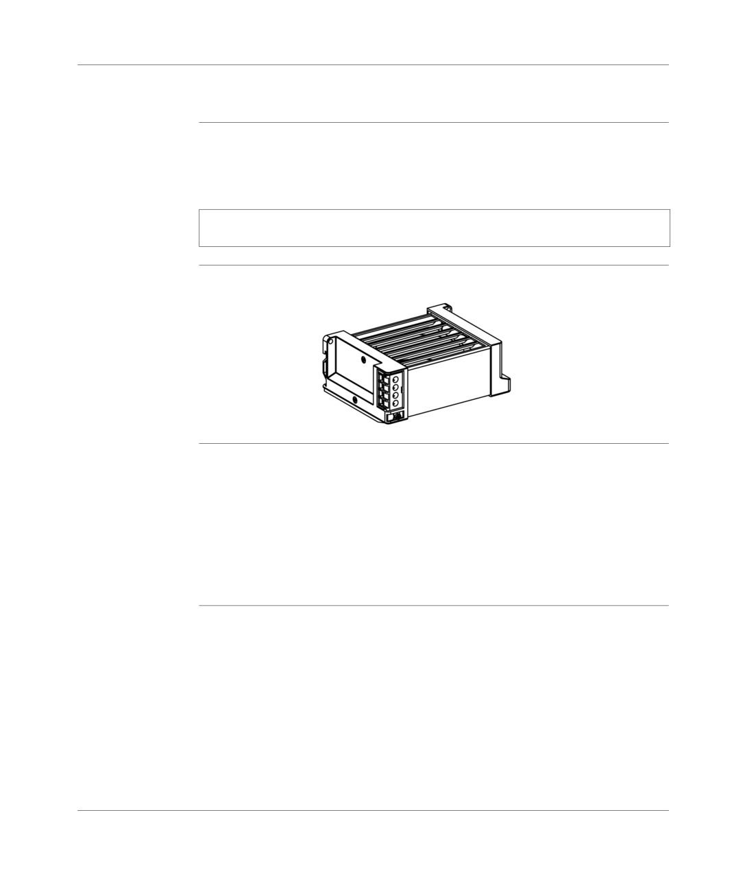
The ventilation modules installed above the TSX Micro PLC station racks ensure a
forced convection of air, so that the ambient temperature inside the envelope is
homogenized, therefore eliminating the various possible hot spots.
Note: A temperature probe built into each module informs the user when the
ambient temperature has reached its maximum value.
Illustration
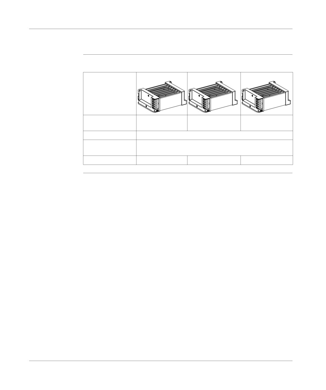
The illustration below shows the ventilation module.
Use of ventilation The use of these modules is recommended in the following cases:
modules
Ambient temperature between 25°C and 60°C: the life of various TSX Micro
PLC components is extended (extension by 25% of the MTBF).
Ambient temperature between 60°C and 70°C:the ambient temperature being
limited to 60°C without ventilation, forced ventilation makes it possible to lower
the temperature inside the modules by 10°C, which brings the internal
temperature of the modules back to the equivalent of 60°C at ambient
temperature.
In these conditions, the product life span is increased by more than 50%.
136
TSX DM 37 xxE
Ventilation module
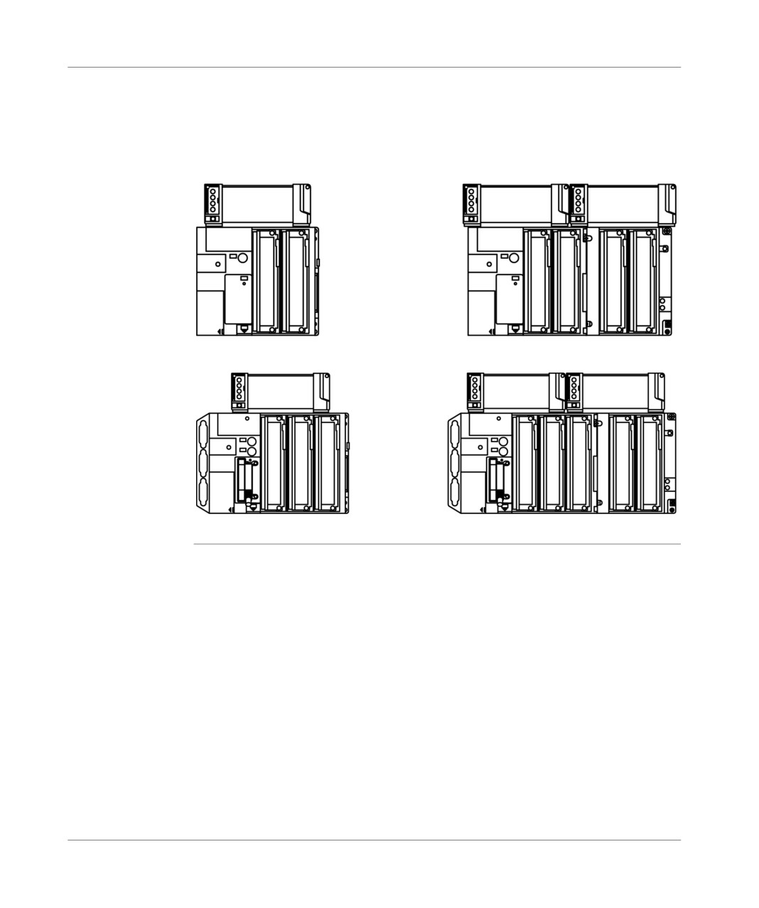
Different module Three ventilation modules are available, adapted to the main supply networks:
types
ventilation module with 24 VDC, 110 VAC or 220 VAC power supply.
According to the type of PLC, TSX 37-05/08/10 or TSX 37-21/22 with or without TSX
RKZ 02 mini extension rack, 1 or 2 ventilation modules must be installed.
TSX 37-05/10 PLCs only
TSX 37-10 + TSX RKZ 02 PLC
TSX 37-08/21/22 PLCs only
TSX 37-21/22 + TSX RKY 02 PLC
TSX DM 37 xxE
137
Ventilation module
Ventilation module: physical presentation
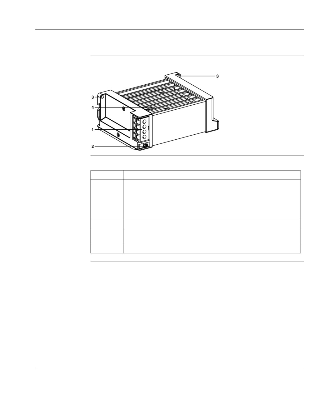
Illustration
Descriptive diagram:
Number table
This table gives the function description of the numbers:
Address
Description
1
Connection terminal block:
of the module supply voltage,
of the heat sensor and LED (or inline pre-actuator) supply. Each terminal
can receive 1 1.5 mm2 wire without a wire end ferrule or 2 1 mm2 wires
with wire end ferrules.
2
Terminal for connecting a module to the ground connection.
3
Module fixing holes (screw M4 x 12), in the case of mounting on a board or
panel.
4
Rotated flap which allows the air to be sent back to the front.
138
TSX DM 37 xxE
Ventilation module
Ventilation module: catalog
Catalog
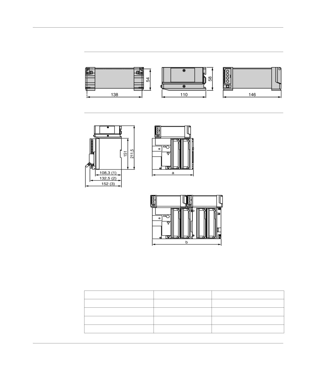
This table shows the different types of ventilation modules:
Power supply
24 VDC
110 VAC
220 VAC
voltage
Temperature probe
Yes (detection of temperature ≥ 80°C +/- 5°C), open on alarm
No. of modules
1 module with TSX 37-10 or TSX 37-21/22 PLC only
2 modules with TSX 37-10 or TSX 37-21/22 PLC + TSX RKZ02
References
TSX FAN D2 P
TSX FAN A4 P
TSX FAN A5 P
TSX DM 37 xxE
139
Ventilation module
Ventilation module: dimensions
Ventilation
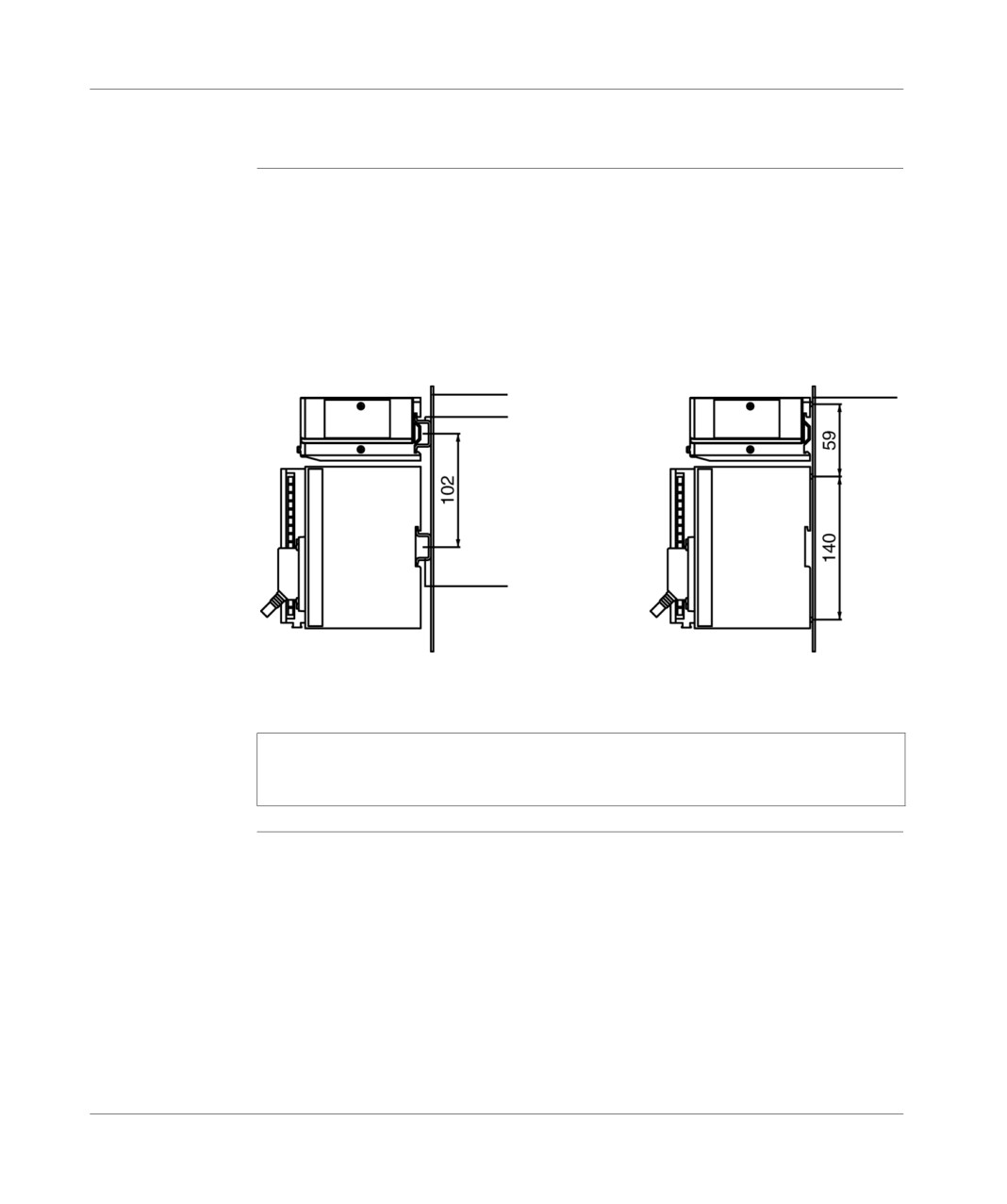
Illustration diagram (sides in millimeters):
module only
Rear view
Right view
Front view
Ventilation
Illustration diagram (sides in millimeters):
module + TSX
Micro
(1) PLC empty,
(2) with screw terminal block modules,
(3) with HE10 connector modules,
(a) TSX Micro PLC dimensions only,
(b) TSX Micro PLC + TSX RKZ 02 extendable rack.
Table of characteristics:
Dimensions
a
b
TSX 37-05 PLC
170.3 mm
-
TSX 37-08 PLC
227.9 mm
-
TSX 37-10 PLC
170.3 mm
282.7 mm
TSX 37-21/22 PLC
227.9 mm
341.4 mm
140
TSX DM 37 xxE
Ventilation module
Ventilation module: mounting
General points
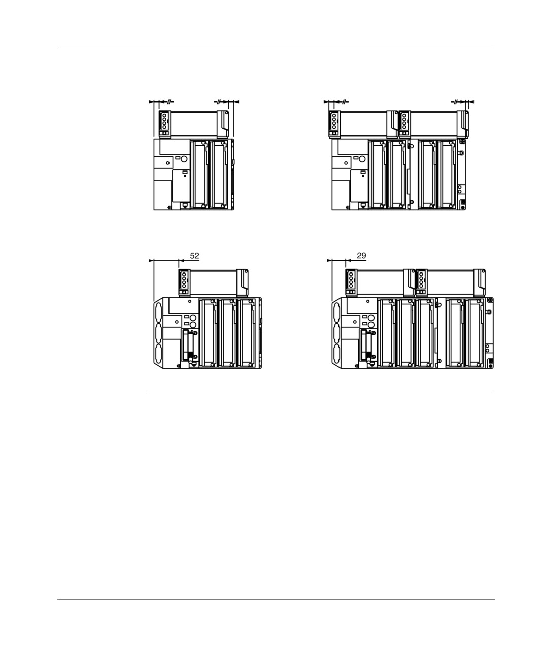
For reasons of mechanical strength, it is imperative to use the same method of fixing
for the PLC and the ventilation module. The dimensions indicated are in millimeters.
Diagram:
Mounting onto a DIN mounting rail
Mounting onto a board (AMI-PA)
(Type AM1-ED)
or panel
Support
Support
Ventilation module
Ventilation module
DIN mounting rail
DIN mounting rail
Fixing ventilation module
using 2 M4x12 screws
Note: Using forced ventilation means it is necessary to take fitting precautions
when analog modules of type TSX AEZ 414 are used in the PLC configuration (see
(TSX Micro Installation manual, Volume 2, cabling recommendations)).
TSX DM 37 xxE
141
Ventilation module
Mounting
Mounting position of the ventilation modules according to the PLC type:
position
TSX 37-05/10 PLCs only
TSX 37-10 + TSX RKZ 02 PLC
TSX 37-08/21/22 PLCs only
TSX 37-21/22 + TSX RKZ 02 PLC
142
TSX DM 37 xxE
Ventilation module
Rules for installation of the racks with ventilation modules
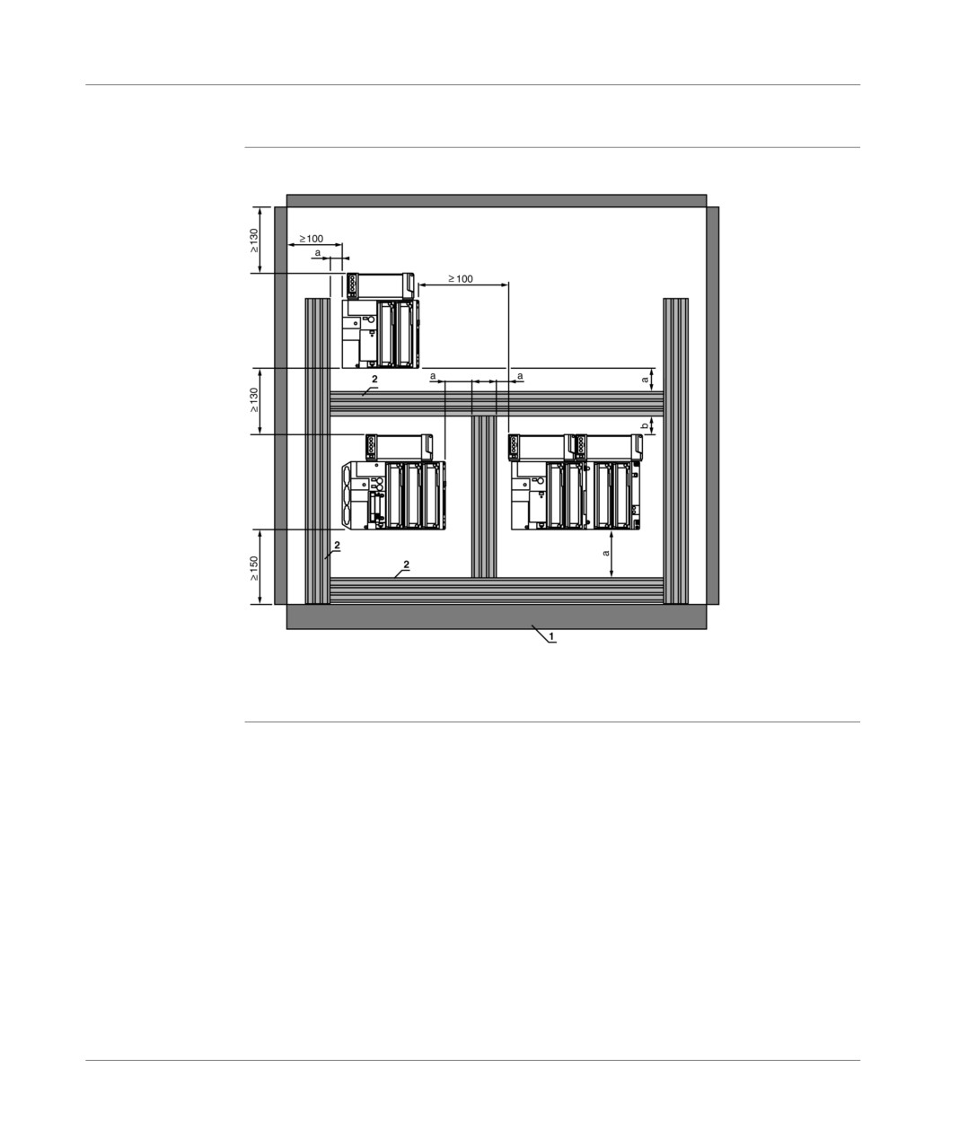
Principle
Illustration:
diagram
a >= 50 mm b >= 30 mm
1 Installation or envelope.
2 Duct or wire quadrant.
TSX DM 37 xxE
143
Ventilation module
Ventilation module: connections
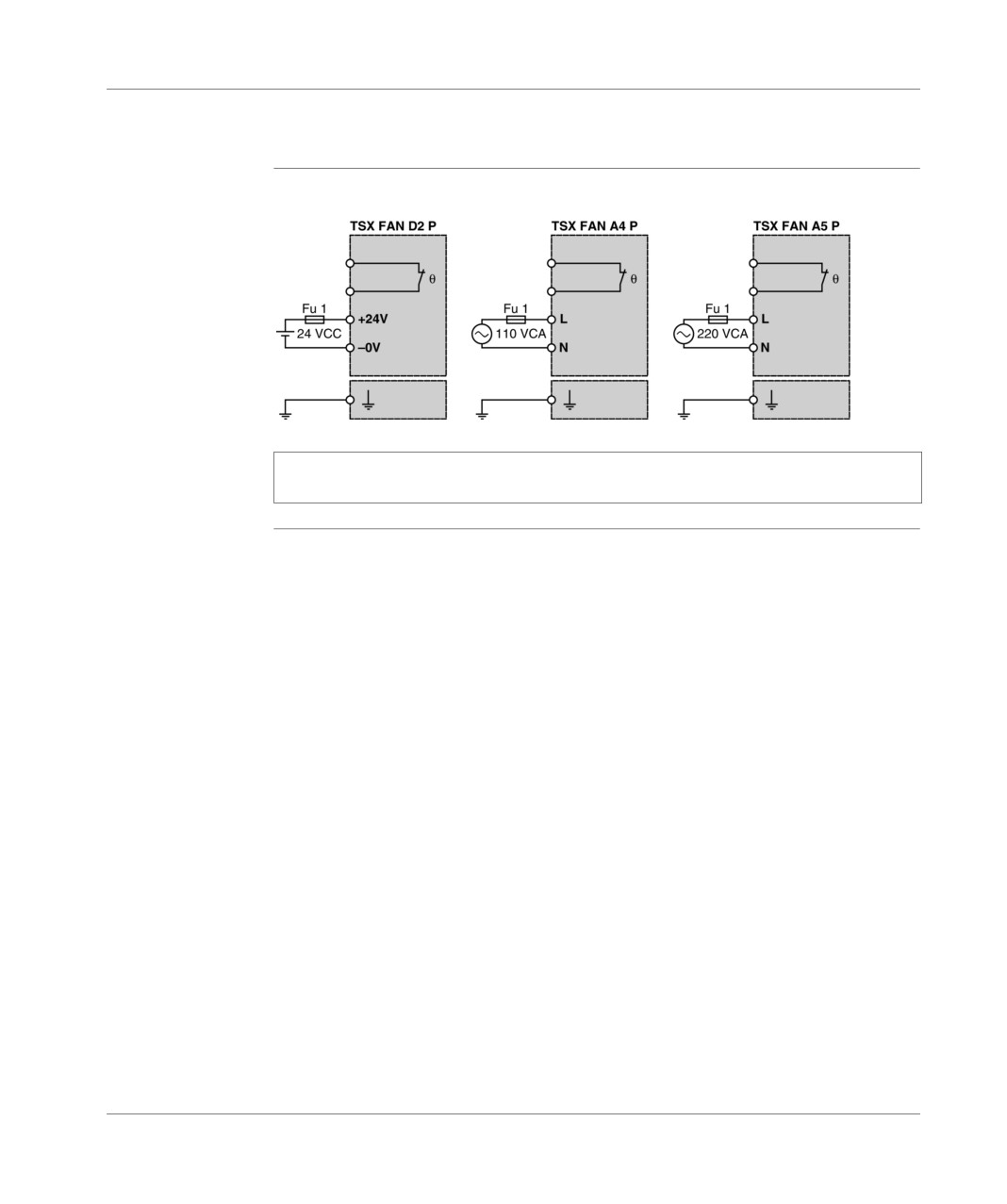
Ventilation
Illustration:
module supply
connection
Note: When using several ventilation modules of the same type, use a shared
supply for all the ventilation modules.
144
TSX DM 37 xxE
Ventilation module
Heat sensor
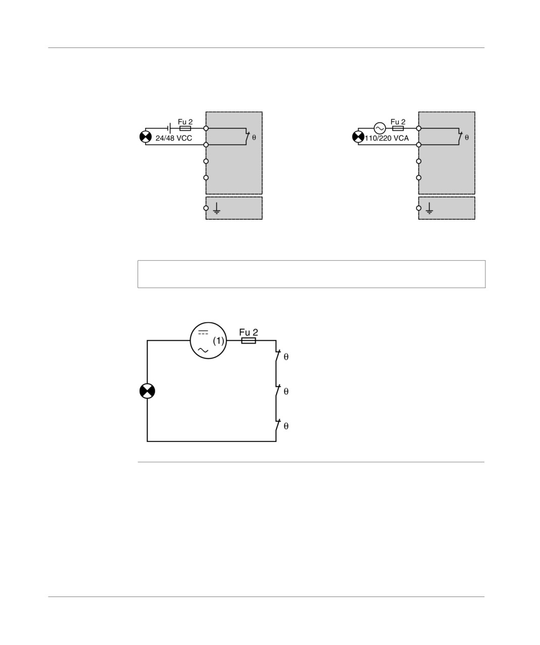
The heat sensor can be supplied either with a direct or alternating current and
supply
connected on a signaling LED, a PLC input etc. .
connection
Illustration diagram:
Directcurrent
Alternating current supply
supply
Note: When using several ventilation modules, the sensor contacts will be put in a
series.
illustration:
Ventilation module 1
Ventilation module 2
Ventilation module 3
(1) direct 24/28 V or alternating 110/220 V.
TSX DM 37 xxE
145
Ventilation module
Ventilation module: characteristics
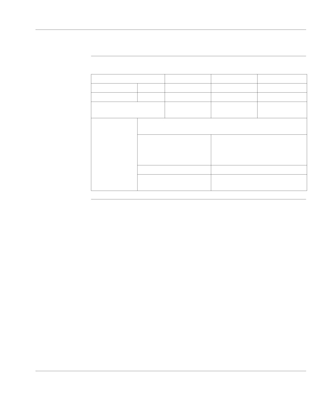
Table of
Table of characteristics of the ventilation modules:
characteristics
Module type
TSX FAN D2 P
TSX FAN A4P
TSX FAN A5P
Supply voltage
Nominal
24 VDC
110 VAC
220 VAC
Limit
20...27.6 VDC
90…120 VAC
180…260 VAC
Current absorbed to
180 mA
180 mA
100 mA
nominal voltage
Heat sensor
Supply voltage: direct 24/48 VDC or alternating 110/220 VAC
Breaking power (on a resistive
1 A to 24 VDC / 10 000 maneuvers
load)
1 A to 48 VDC / 30 000 maneuvers
1 A to 110 VAC / 30 000 maneuvers
0.5 A to 220 VAC / 10 000 maneuvers
Trigger
Temperature >= 75ºC +/- 5ºC
State
closed if temperature <= 75ºC +/- 5ºC
open if temperature >= 75ºC +/- 5ºC
146
TSX DM 37 xxE
Commissioning/Diagnostics/
Maintenance
IV
At a Glance
Aim of this Part
This part deals with commissioning, diagnostics and maintenance.
What's in this
This Part contains the following Chapters:
part?
Chapter
Chaptername
Page
17
Display panel
149
18
Display of language objects
169
19
Commissioning
185
20
Maintenance
191
TSX DM 37 xxE
147
Commissioning/Diagnostics/Maintenance
148
TSX DM 37 xxE

Display panel
17
At a Glance
Aim of this
This chapter deals with the display panel for the TSX Micro PLCs.
Chapter
What's in this
This Chapter contains the following Maps:
Chapter?
Topic
Page
Introduction
150
PLC status display
152
Local input/output status display
154
64 channel modules display
156
Sequencing of the displays
158
Display of faulty local inputs/outputs
159
Display of remote inputs/outputs on the AS-i bus
161
Display of the presence of each slave on the AS-i bus (R I/O mode - DIAG)
162
Display of the status of the input/output bits for each slave (R I/O mode)
164
Incrementation of the slave number in ascending or descending order
166
Specific standard functions
167
Management of the battery LED (BAT)
168
TSX DM 37 xxE
149
Display panel
Introduction
Introduction
The display panel offers a centralized array of services essential to PLC installation,
use, diagnostics and maintenance, for all the modules positioned in the base rack
or in the mini extension rack and the remote discrete inputs/outputs on the nano PLC
or AS-i bus:
PLC status display,
Local or remote input/output status display,
discrete input/output wiring test, in the absence of the application program,
Input/output and module diagnostics,
Display of the program internal data (bits, words, remote input/output bits, etc.).
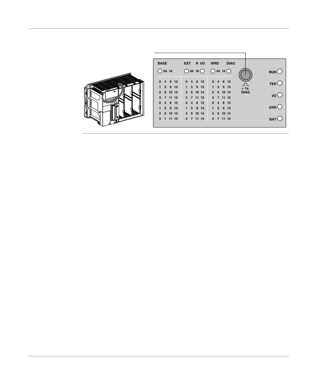
Description
The display panel offers:
on the right, 5 status LEDs, which display the functioning of the PLC (RUN, TER,
I/O, ERR, BAT),
above, 5 status LEDs, which show the current display mode:
BASE LED: base input/output display mode,
EXT LED: mini extension rack input/output display mode,
R I/O LED: inputs/outputs on the AS-i bus display mode,
WRD LED: language objects display mode,
DIAG LED: diagnostic mode,
3 panels of 32 LEDs, which give information about the modules in the PLC or the
extension: discrete inputs/outputs status, faulty channels or modules. Further,
each panel is completed by 2 slot LEDs ("64" and "16"), which allow a double
display of the 64 channel modules (16 first input channels and 16 first output
channels, then 16 following input/output channels),
a push button, which allows the display of the rest of the information and/or the
alteration of the display mode (input/output or diagnostic display mode). In
WORD mode, this push button allows the choice of the displayed objects table.
150
TSX DM 37 xxE
Display panel
Illustration
Display mode on the TSX Micro:
Push button
TSX DM 37 xxE
151

Display panel
PLC status display
Introduction
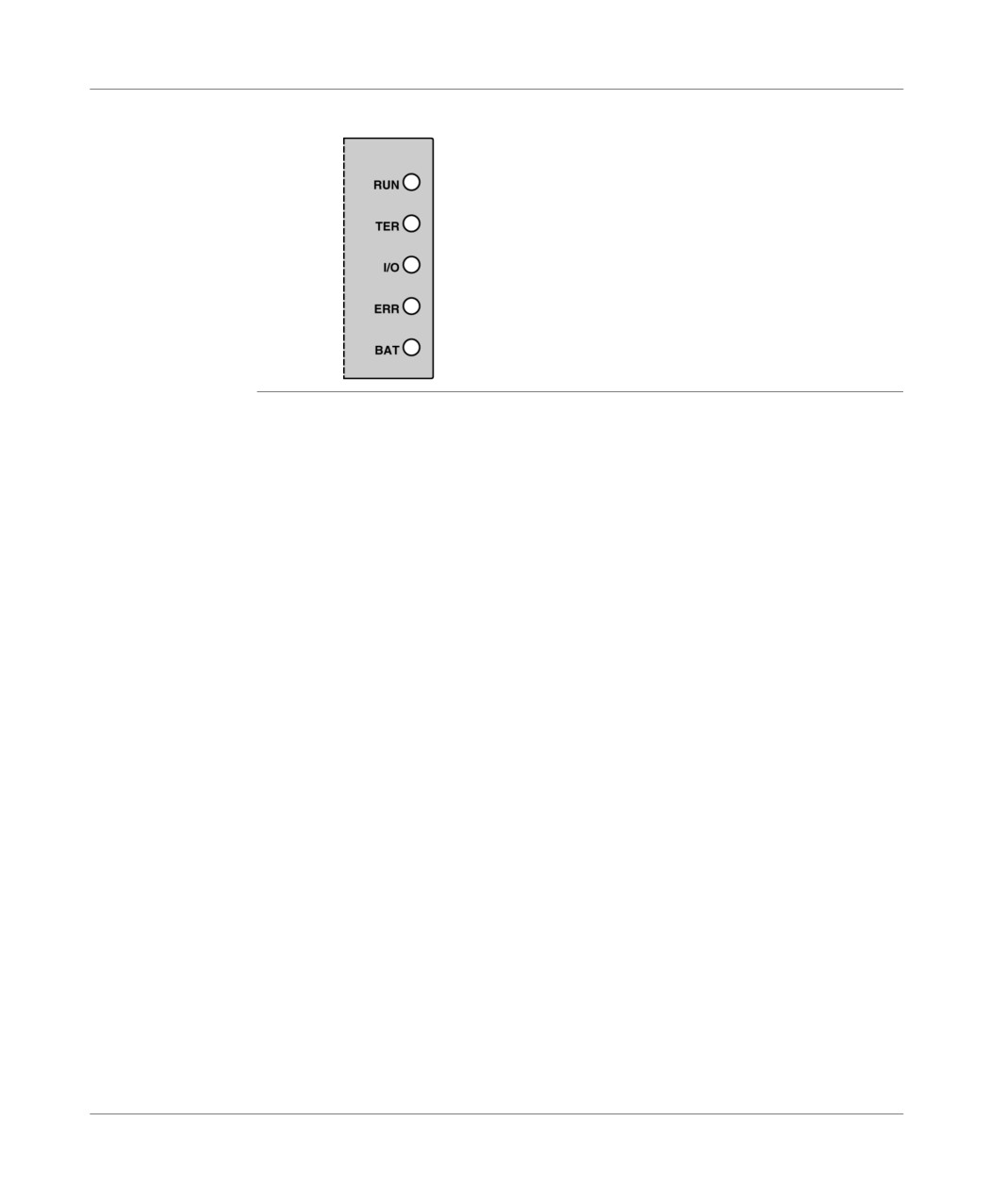
The display uses the 5 LEDs RUN, TER, I/O, ERR and BAT, which by means of their
status (LED off, blinking or on) provide information on the operating mode of the
PLC:
Description
this table describes the PLC status for each of the LEDs:
Display
Status
LED
RUN
this LED (green) is lit to indicate that the PLC is in RUN mode, and flashes to
indicate that it is in STOP mode. This LED is off when there is no valid
application in the PLC or when there is a fault.
TER
this LED (yellow) is lit to show that information is being exchanged by the
terminal link. Traffic via the terminal port may appear to make this LED flash.
I/O
this LED (red) is lit to show a fault relating to the inputs/outputs:
supply fault or at least one channel tripped,
module missing, not configured or out of service.
For more information on the errors shown by the I/O LED (faulty channel or
module), the push button must be depressed for more than one second to go
to diagnostics mode (See Display of remote inputs/outputs on the AS-i bus,
p. 161).
ERR
this LED (red) is lit to show a PLC "CPU fault": This LED flashes when there is
no valid application in the PLC or if there is a "blocking fault (See Researching
the errors from PLC status monitors., p. 192)" in the application program.
BAT
this LED (red) is lit to show that the battery is defective or missing (optional).
This battery, which is used to back up the RAM, must be changed in
accordance with the proper procedure (see Inserting/changing the battery,
p. 110).
If the %S66 bit system is at 1, the lighting of this LED is inhibited.
152
TSX DM 37 xxE
Display panel
Summary
Illustration:
Start/stop PLC
Traffic on the terminal port
Inputs/outputs error (channel or module)
Processor or application error
Absence or error of the battery
TSX DM 37 xxE
153
Display panel
Local input/output status display
General
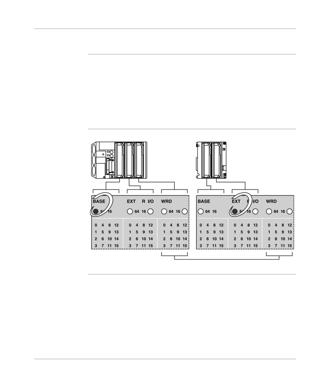
The display comes from the 2 panels of 32 LEDs on TSX 37-05/10 and 3 panels of
32 LEDs on TSX 37-08/21/22, which allows the simultaneous display of the input/
output status of 2 or 3 modules. These modules are positioned in the 2 or 3 base
slots or in the two slots in the mini extension rack. A short press of the push button
selects the group displayed: base (the BASE LED is lit) or the mini extension rack
(the EXT LED is lit).
Only the discrete module channels present in the configuration are displayed. The
discrete inputs/outputs of the application specific function (if they exist) and the
remote discrete inputs/outputs (TSX 07 module) are not displayed.
Illustration
Principle diagram:
Not used on the TSX 37 10 PLC
154
TSX DM 37 xxE
Display panel
Panel
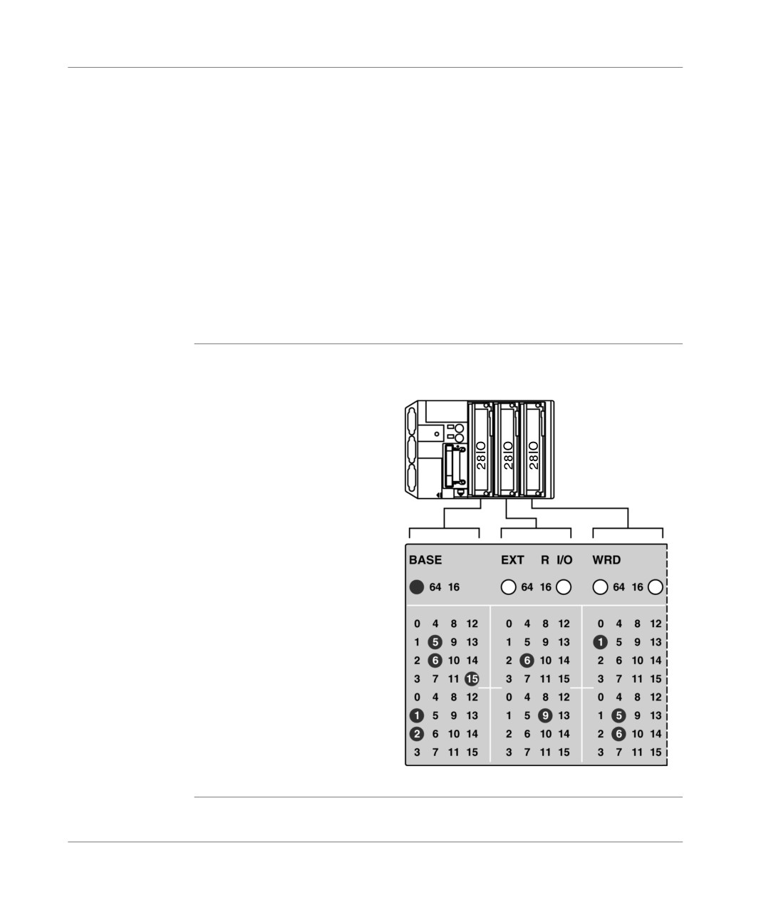
The 3 panels of 32 LEDs indicate the status of each of the channels of the modules
description
displayed.
If the channel is at the status 1, the LED corresponding to the position is lit, if this is
not the case, it remains off.
Supposing for example that the PLC is equipped with the following modules:
1 module 28 inputs/outputs in positions 1 and 2,
1 module 28 inputs/outputs in positions 3 and 4,
1 module 8 inputs in position 5,
1 module 8 inputs in position 6,
In the example below, the following inputs and outputs are at the status 1:
%I1.5, %I1.6, %I1.15, %Q2.1 and %Q2.2,
%I3.6 and %Q4.9,
%I5.1,
%Q6.5 and %Q6.6.
Example
Illustration:
1
3
5
2 4
6
Position 1, 3 and 5
Position 2, 4 and 6
TSX DM 37 xxE
155
Display panel
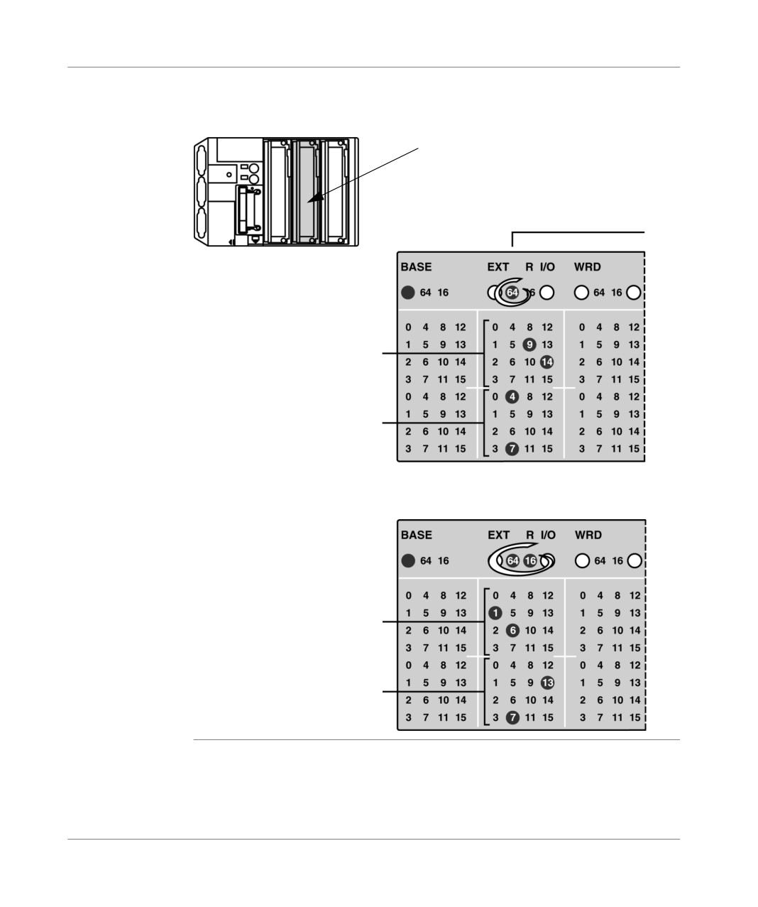
64 channel modules display
General
The 64 channel modules, which cannot be displayed together are shown by slot
level (the "64" LED is lit). A short press on the push button displays either the first
16 inputs and the first 16 outputs (only the "64" LED is lit), or the following 16 inputs
and the following 16 outputs (the "64" and "16" LEDs are lit).
156
TSX DM 37 xxE
Display panel
Example
Supposing that the second PLC slot (position 3 and 4) is equipped with a 64 channel
module:
1
3
5
64 I/O module
2nd PLC slot
2
4
6
First 16 inputs %I3.0 to %I3.15
Here, the inputs %I3.9 and
I3.14% are at 1
First 16 outputs
%Q4.0 to %Q4.15
Here, the outputs %Q4.4
and %Q4.7 are at 1
Pressing the push button briefly
Next 16 inputs
%I3.16 to %I3.31
Here, the inputs %I3.17 (16+1)
and %I3.22 (16+6)
are at 1
Next 16 outputs
%Q4.16 to %Q4.31
Here the outputs %Q4.23 (16+7)
and %Q4.29 (16+13) are at 1
TSX DM 37 xxE
157
Display panel
Sequencing of the displays
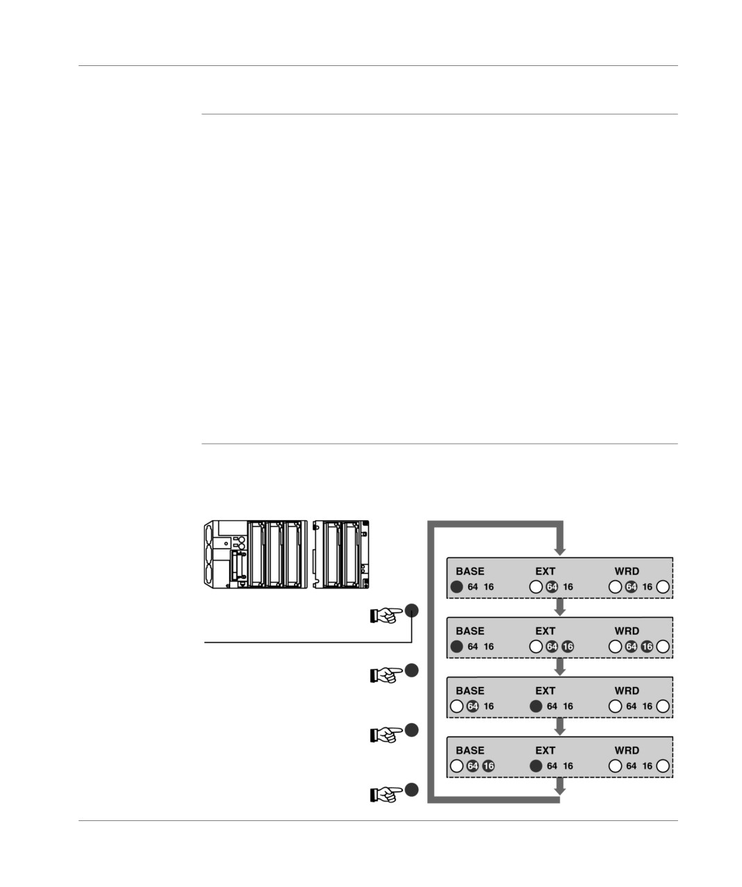
General
Since the display of all the discrete inputs/outputs (base+PLC) is performed by short
presses on the push button, the sequencing of the displayed channels therefore
depends on the configuration (presence of modules in the mini extension rack,
presence of 64 input/output modules). Several possible cases can be identified:
PLC only (base), without 64 I/O module
The push button has no effect (except for entering diagnostic mode),
PLC only, with 64 I/O module(s)
Base (1st 32 I/O) --> Base (following 32 I/O) --> Base (32 1st I/O) --> etc,
PLC with extension, without 64 I/O module
Base --> Extension --> Base --> Extension --> etc,
PLC with extension, with 64 I/O module(s) in the base
Base (1st 32 I/O) --> Base (following 32 I/O) -->Extension --> Base (1st 32 I/O) -
-> Base (following 32 I/O) -->etc,
PLC with extension, with 64 I/O module(s) in the extension
Base --> Extension (1st 32 I/O) --> Extension (following 32 I/O) -->Base -->
Extension (1st 32 I/O) --> etc,
PLC with extension, with 64 I/O module(s) in the base and the extension
Base (1st 32 I/O) --> Base (following 32 I/O) -->Extension (1st 32 I/O) -->
Extension (following 32 I/O) -->Base (1st 32 I/O) --> etc.
Example
Supposing for example that a TSX 37-21 PLC is equipped with a 64 input/output
module in positions 3/4, 5/6 and 7/8. The display sequence, therefore, the LEDs
BASE, EXT, 64 and 16 will follow when the push button is pressed briefly.
Illustration:
Push button
158
TSX DM 37 xxE
Display panel
Display of faulty local inputs/outputs
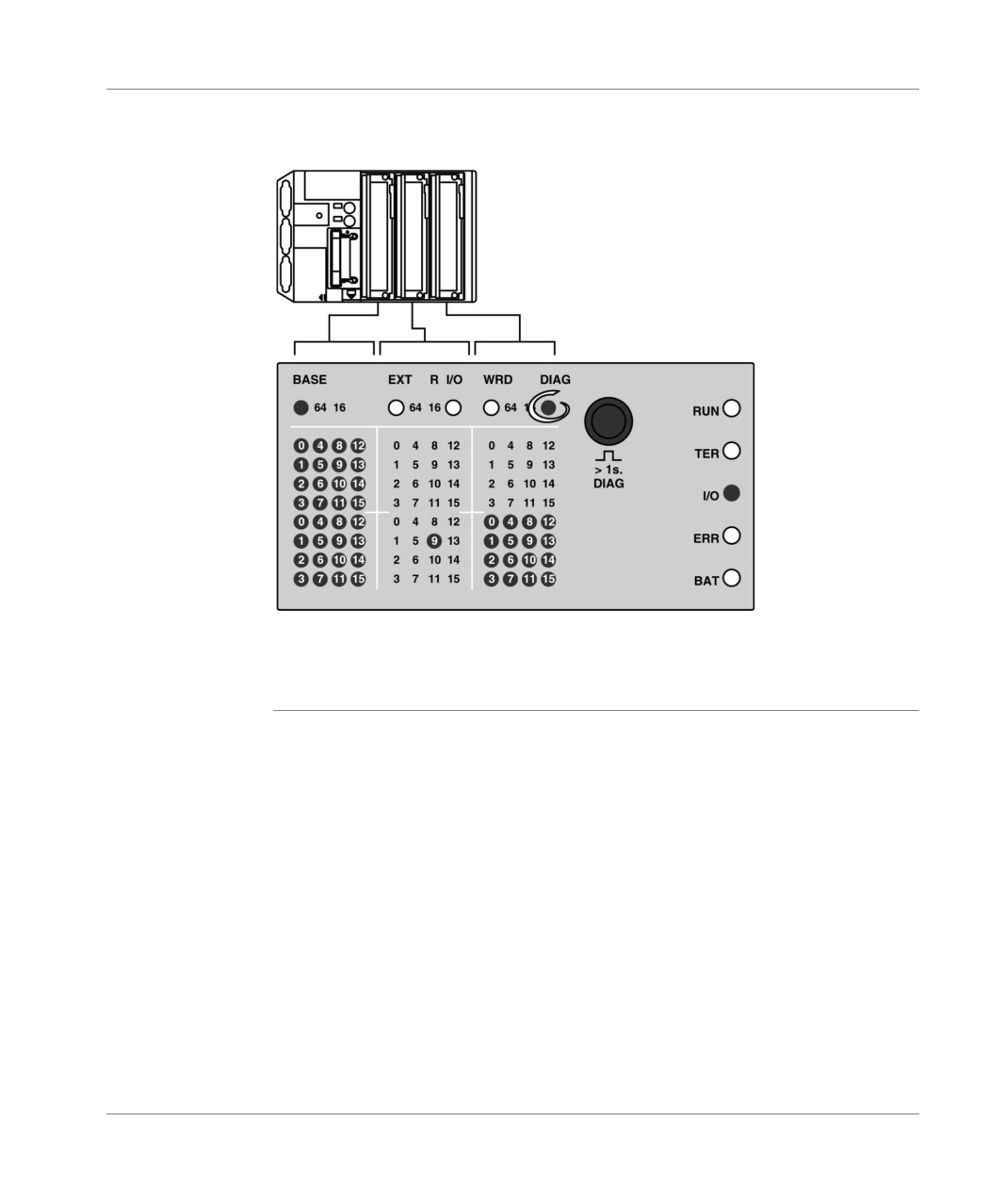
General
The faults are displayed in diagnostic mode, accessed by a long press on the push
button (more than 1 second). The DIAG LED, which signals this mode, is therefore
lit.
Principle
The faulty inputs/outputs and/or modules are displayed by 3 panels of 32 LEDs:
if an input or output is faulty (defective power supply, output tripped, etc.), the
associated LED flashes rapidly,
if a module is faulty (absent module, module not configured properly, module out
of service, etc.), all the corresponding LEDs flash slowly:
16 LEDs for a half-size module (top or bottom of a display panel),
32 LEDs for a standard size module with 28 inputs/outputs (entire display zone
of the module),
64 LEDs for a standard size module with 64 inputs/outputs (entire display zone
of the module with the 64 only or 64 and 16 LEDs).
All the input/output faults are displayed by short presses on the push button, with the
same sequences as with the input/output status display mode. A long press of the
push button returns to the input/output status display.
Note: Contrary to the input/output status display mode, which is only accessible for
the discrete modules, the diagnostic mode displays the faulty channels associated
with the analog and counting modules. For example, if a PLC contains a TSX CTZ
2A module in position 3, a fault with the counting channel 0 is signaled by a rapid
blinking of LED 0 on the upper part of the corresponding zone.
TSX DM 37 xxE
159
Display panel
Example
Illustration:
1
3
5
2
2
2
8
8
8
E
E
E
S
S
S
2
4
6
This example illustrates a fault in the 28 I/O and 8 O modules, positioned
respectively in 1/2 and 6 (the LEDs corresponding to the module slot flash slowly).
The %Q4.9 output is also faulty (the corresponding LED flashes rapidly).
160
TSX DM 37 xxE
Display panel
Display of remote inputs/outputs on the AS-i bus
At a Glance
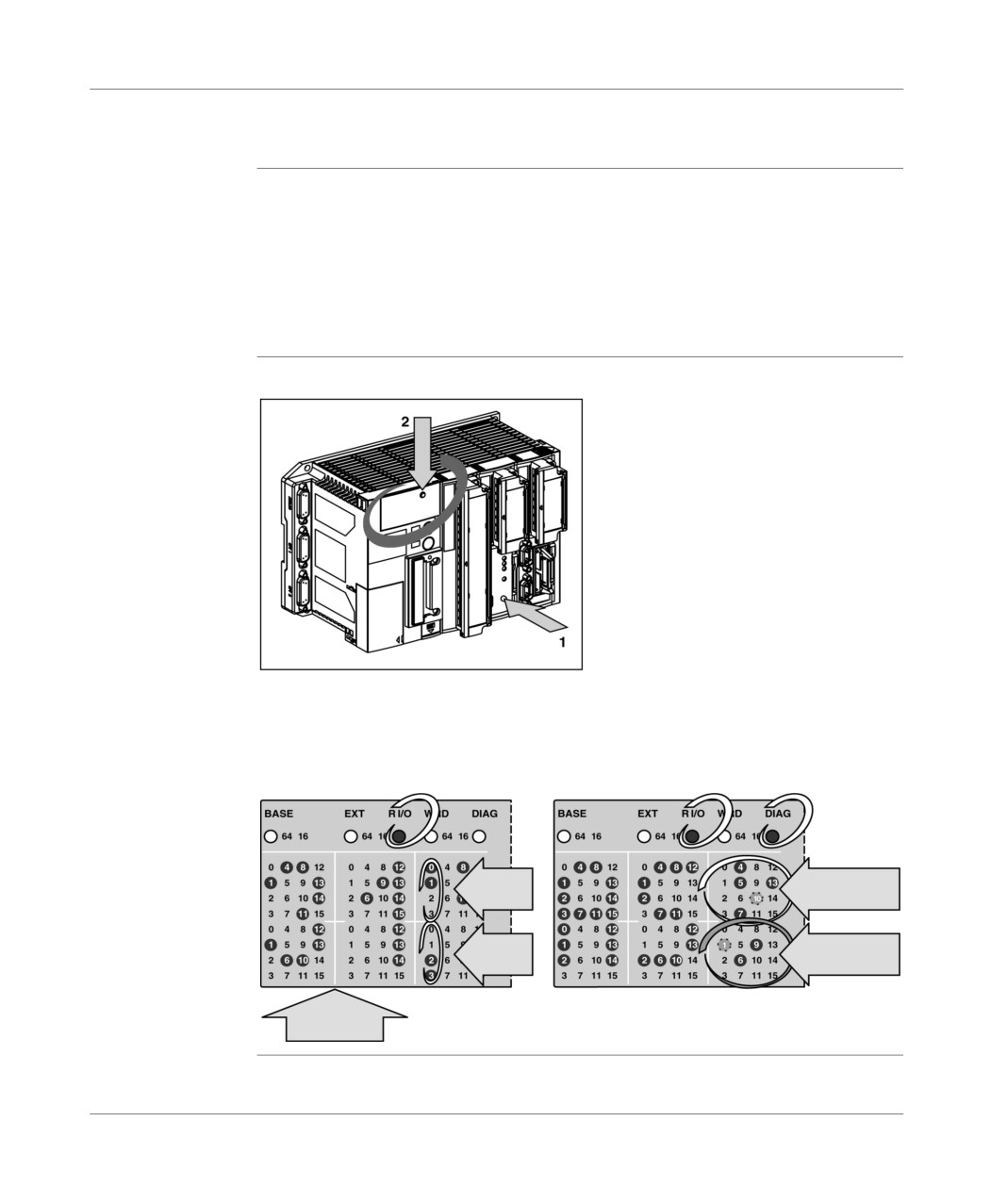
The PLC display panel allows:
the presence of each slave on the AS-i bus, (DIAG mode), to be displayed,
the status of the input/output bits of each slave present on the bus (R I/O mode -
DIAG) to be displayed.
These modes can be accessed by a combination of actions on the push buttons (1)
of the TSX SAZ10 module and (2) on the PLC display block.
Illustration
highlighting the display screen:
Display of the state of the bits
Display of the presence of
of inputs/outputs of each
each bus AS-i bus slave
slave (mode R I/O)
(mode R I/O - DIAG)
States of
Presence of
input bits
slaves 1 to 15
States of
Presence of
output bits
slaves 16 to 31
Slave
number
TSX DM 37 xxE
161
Display panel
Display of the presence of each slave on the AS-i bus (R I/O mode - DIAG)
Introduction
This mode makes it possible to display:
the slaves which have been installed and detected (LEDs permanently on),
slaves which have not been installed or detected (LEDs off),
slaves which have been installed but not detected or not installed but detected
(LEDs on and blinking).
Procedure for
Carry out the following steps:
access
Step
Action
1
Initial status of display block:
local input/output display mode (Base or EXT LEDs on).
2
A short press on the push button (1), of the TSX SAZ module allows the switch
to R I/O mode.
3
A long press on the push button (2) on the PLC display block allows the switch
to diagnostics mode.
The image of the AS-i network is then displayed on the right-hand block, with
each LED representing an address of an AS-i bus slave. All of the ALEDs
represent the addresses of the slaves 0 to 15, all the B LEDs represent the
addresses 16 to 31 (add + 16 to the figure displayed to get the exact address
of the slave).
4
To return to the initial status:
A long press on the push button (2) on the display block (to exit the AS-i
bus diagnostics mode),
A short presson the push button (1) on the TSX SAZ module (to return to
local input/output display mode).
162
TSX DM 37 xxE