TSX Micro PLCs TSX 3705/3708/3710/3720. Implementation Manual (Volume 1) - page 2

TSX 37 PLC
II
At a Glance
Aim of this Part
This part is about the TSX 37-05, TSX 37-08, TSX 37-10 and TSX 37- 21/22 PLCs.
What's in this
This Part contains the following Chapters:
part?
Chapter
Chaptername
Page
5
TSX 37-05 PLC
45
6
TSX 37-08PLC
51
7
TSX 37-10PLC
57
8
TSX 37-21 and TSX 37-22 PLCs
63
9
TSX 37 PLC supplies
71
10
Memories on TSX 37
75
11
Mini extention rack
81
12
TSX 37 PLC performance
85
13
Commissioning standards and conditions
87
TSX DM 37 xxE
43
TSX 37 PLC
44
TSX DM 37 xxE

TSX 37-05 PLC
5
At a Glance
Aim of this
This chapter is about the TSX 37-05 PLC, its physical description and its technical
Chapter
characteristics.
What's in this
This Chapter contains the following Maps:
Chapter?
Topic
Page
Introduction to the TSX 37 05 PLC base
46
TSX 37-05: physical description
48
Characteristics of the TSX 37-05
49
Display panel on TSX 37-05
50
TSX DM 37 xxE
45
TSX 37-05 PLC
Introduction to the TSX 37 05 PLC base
General points
A TSX 37-05 PLC base groups under one product reference:
a rack comprising the supply to the base (100-240V AC), the processor, the
dedicated memory, the watchdog in FLASH EPROM and two half-slots for the
modules,
a discrete module of 28 standard size inputs/outputs in the first slot in the rack.
Catalog data
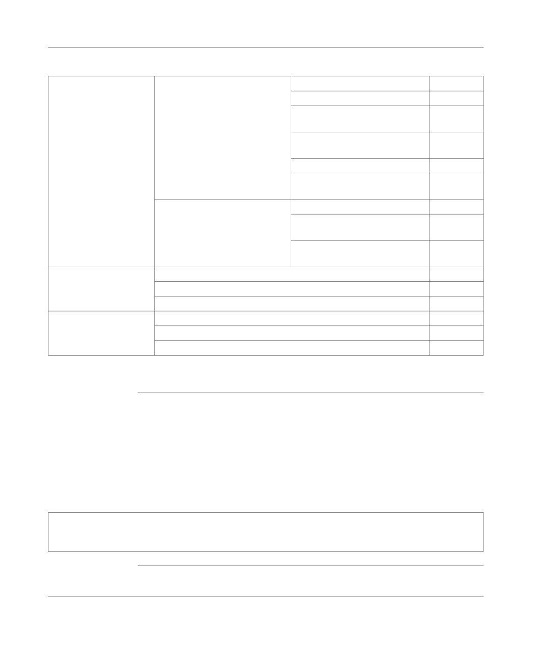
data table:
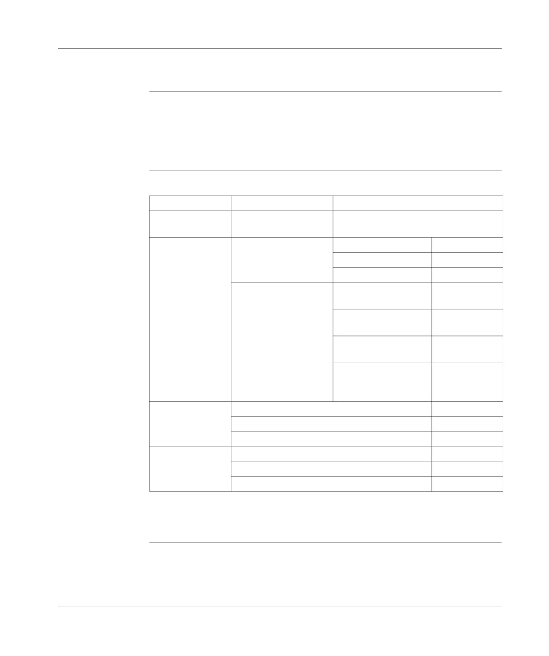
Reference Number
Supply
Built-in input/output module
TSX 3705 028DR1
100240V AC
TSX DMZ 28DR: 16 24V DC inputs,
12
relay outputs
Discrete inputs/
Maximum number of
in the base (1)
92
outputs
discrete I/Os
remote (TSX 07)
0
remote on the AS-i bus
0
Maximum number of
28 discrete inputs/
2
modules (2)
outputs
32 discrete inputs/
1
outputs
64 discrete inputs/
1
outputs (high density)
input/output mismatch
0
(for TSX 07 I/O or AS-i
bus)
Analog
Number of analog input/output modules (2)
2
No. of analog inputs
16
No. of analog outputs
8
Counting
No. of 500Hz counting channels on discrete inputs
2
No. of counting modules (2)
2
No. of 40kHz or 500kHz counting channels
4
(1) with 1 64 input/output module with HE10 connectors,
(2) taking into account the available slots, the number of modules cannot be
cumulated.
46
TSX DM 37 xxE
TSX 37-05 PLC
RS 485 terminal
With an 8-point mini-DIN size RS 485 terminal port, it is possible to:
port
connect an FTX type terminal or a compatible PC, a printer,
and to connect the PLC to the UNI-TELWAY or Modbus busses. For this, it
proposes, by default, the UNI-TELWAY 96 Baud master communication mode
and, by configuration:
the UNI-TELWAY slave mode or,
ASCII character mode or,
the Modbus protocol.
Note: The terminal and PLC can both be connected to the UNI-TELWAY bus using
the TSX P ACC 01 insulating device. This should be used when the distance
between the UNI-TELWAY connection equipment is greater than 10 meters (see
TSX unit P ACC 01, p. 345).
TSX DM 37 xxE
47
TSX 37-05 PLC
TSX 37-05: physical description
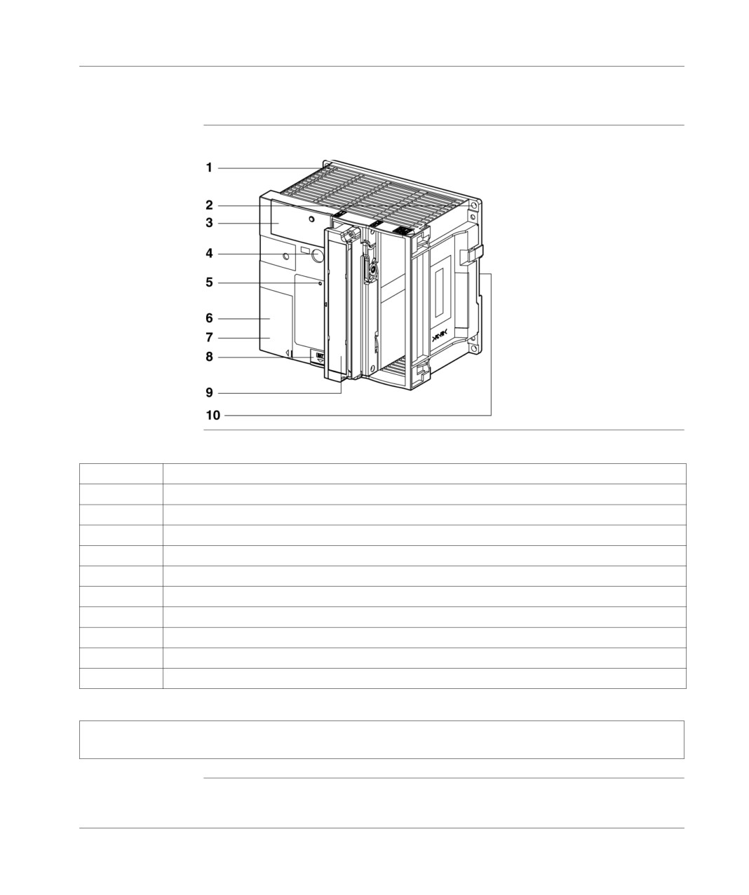
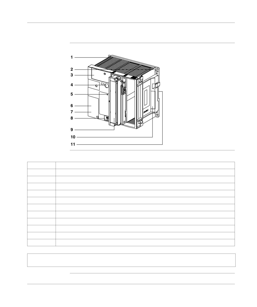
Illustration
TSX 37-05:
Number table
function description of the numbers:
Number
Description
1
2 slot rack comprising the supply, the processor and its memory.
2
Fixing hole for the PLC.
3
Centralized display panel.
4
Terminal port (TER).
5
RESET button.
6
Access door to the supply terminals.
7
Stack change information label.
8
Access door to the optional stack and data protection switch for the operating system.
9
A 28 I/O module whose basic position is in the first slot.
10
Mounting device on DIN mounting rail.
Note: For an IP20 protection index, place the protection covers in the empty slots. These covers, which
are not supplied, should be ordered in batches of 10, quoting the reference TSX RKA 01.
48
TSX DM 37 xxE
TSX 37-05 PLC
Characteristics of the TSX 37-05
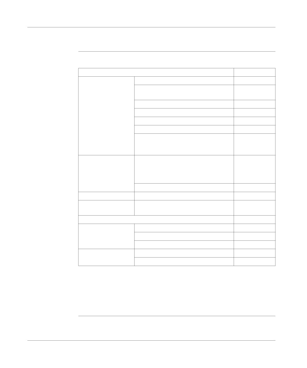
Table of
Technical characteristics:
characteristics
PLCs
TSX 37-05
Functions
No. of local discrete inputs/outputs
92
No. of remote discrete inputs/outputs (TSX 07
0
and AS-i)
No. of integrated UNI-TELWAY connections
1
Communication modules
0
Real-time clock
No
Integrated analog
No
Integrated upcounting
-500Hz (on discrete input)
Yes
-10kHz
No
Memory
Savable internal RAM
9 Kwords
- program (100% Boolean)
2/1.6 Kinst. (1)
- data
1 Kwords (2)
- constant
128 words (2)
Integrated Flash Eprom
10 Kwords (3)
Memory extension
-
No
Execution time by
RAM (100% Boolean)
0.3ms
Kinst.(5)
System overhead
1.9 ms
Application structure
Master task
1
Fast task
1
Processing on events
1 to 8
Pre-defined function
Timers
64
(4)
blocks
Counters
32
(1) The first value corresponds to a program in List. The 2nd value corresponds to a
program in Ladder language.
(2) Size by default; can be extended at the expense of the application program size.
(3) 9 Kwords available for the backup application + 1 Kword for the %MW backup.
(4) A maximum of 16 timers with a 10ms time base.
(5) Inoperative overhead and I/O management.
TSX DM 37 xxE
49
TSX 37-05 PLC
Display panel on TSX 37-05
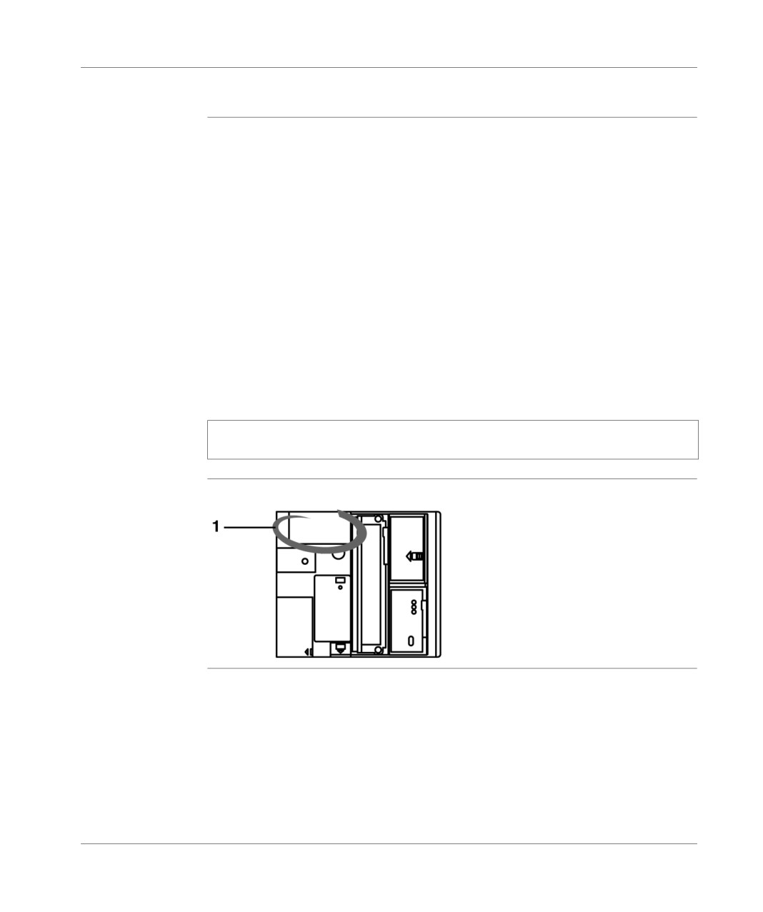
General points
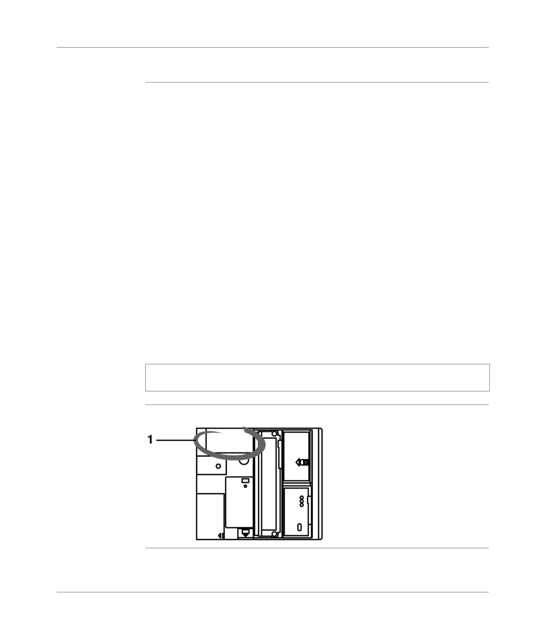
The display block 1 centralizes all the information needed for diagnostics and for
maintenance of the PLC and its modules. For this, it provides the following:
8 LED status displays giving PLC function information ( RUN, TER, I/O, ERR and
BAT LEDs) and the current display mode (R, I/O, WRD and DIAG LEDs),
from a block of 96 LED displays making it possible to display:
local inputs/outputs in display mode (BASE LED on): the state of all
discrete inputs and outputs of the PLC,
in diagnostic mode (DIAG LEDs on):
"module" errors (all LEDs associated with the module flash slowly),
or
"channel" errors (LED display associated with the channel),
in object display mode (WRD LED on): the contents of a maximum of 16
%MWi, %SWi, or %KWi words (these words are displayed in binary or
hexadecimal), the state of a group of 64 %Mi, %Si or %Xi bits,
a push button which enables the information sequence to be viewed and to
change the display mode.
Note: For further information concerning the display block, please refer to
theDisplay panel, p. 149
Illustration
display panel:
50
TSX DM 37 xxE
TSX 37-08PLC
6
At a Glance
Aim of this
This chapter is about the TSX 37-08 PLC, its physical description and its technical
Chapter
characteristics.
What's in this
This Chapter contains the following Maps:
Chapter?
Topic
Page
Introduction to the TSX 37 -08 PLC base
52
TSX 37-08: physical description
54
Characteristics of the TSX 37-08
55
Display panel on TSX 37-08
56
TSX DM 37 xxE
51
TSX 37-08 PLC
Introduction to the TSX 37 -08 PLC base
Introduction to
A TSX 37-08 PLC base groups under one product reference:
the TSX 37 08
a rack comprising the supply to the base (100-240V AC), the processor, the
PLC base
dedicated memory, the watchdog in FLASH EPROM and two half-slots for the
modules,
2 standard size discrete 28 input/output modules in the first two rack slots.
Catalog data
data table:
Reference Number
Supply
Integrated input/output modules
TSX 3708 056DR1
100240V AC
TSX DMZ 28DR: 16 24V DC inputs, 12
relay outputs
Discrete inputs/
Maximum number of
in the base (1)
120
outputs
discrete I/Os
remote (TSX 07)
0
remote on the AS-i bus
0
Maximum number of
28 discrete inputs/outputs
3
modules (2)
32 discrete inputs/outputs
1
64 discrete inputs/outputs
1
64 discrete inputs/outputs
0
(high density)
input/output mismatch (for
0
TSX 07 I/O or AS-i bus)
Analog
Number of analog input/output modules (2)
2
No. of analog inputs
16
No. of analog outputs
8
Counting
No. of 500Hz counting channels on discrete inputs
2
No. of counting modules (2)
2
No. of 40kHz or 500kHz counting channels
4
(1) with 1 64 input/output module with HE10 connectors,
(2) taking into account the available slots, the number of modules cannot be
cumulated.
52
TSX DM 37 xxE
TSX 37-08 PLC
RS 485 terminal
With an 8-point mini-DIN size RS 485 terminal port, it is possible to:
port
connect an FTX type terminal or a compatible PC, a printer,
and to connect the PLC to the UNI-TELWAY or Modbus busses. For this, it
proposes, by default, the UNI-TELWAY 96 Baud master communication mode
and, by configuration:
the UNI-TELWAY slave mode or,
ASCII character mode or,
the Modbus protocol.
Note: The terminal and PLC can both be connected to the UNI-TELWAY bus using
the TSX P ACC 01 insulating device. This should be used when the distance
between the UNI-TELWAY connection equipment is greater than 10 meters (see
TSX unit P ACC 01, p. 345).
TSX DM 37 xxE
53
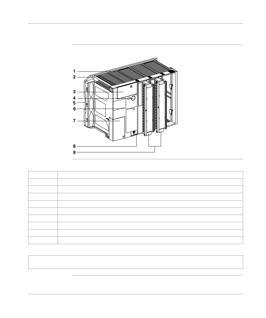
TSX 37-08 PLC
TSX 37-08: physical description
Illustration
TSX 3708:
Address table
description for each address:
Address
Description
1
3 slot rack containing the supply, the processor and its base memory.
2
PLC fixing hole.
3
Centralized display block.
4
Terminal port (TER).
5
Mounting device on DIN mounting rail.
6
RESET button.
7
Access door to the supply terminals.
8
Access door to the optional battery and to the operating system data protection switch.
9
Two 28 I/O modules, positioned as standard in the first two slots.
Note: For an IP20 protection rating, place protection covers in the empty slots. These covers, which are
not supplied, should be ordered separately in lots of 10, quoting the reference TSX RKA 01.
54
TSX DM 37 xxE

TSX 37-08 PLC
Characteristics of the TSX 37-08
Table of
Technical characteristics:
characteristics
PLCs
TSX 37-08
Functions
No. of local discrete inputs/outputs
120
No. of remote discrete inputs/outputs
0
(TSX 07 and AS-i)
No. of integrated UNI-TELWAY
1
connections
Communication modules
0
Real-time clock
No
Integrated analog
No
Integrated upcounting
-500Hz (on discrete input)
Yes
-10kHz
No
Memory
Savable internal RAM
9 Kwords
program (100% Boolean)
2/1.6 Kinst. (1)
data
1 Kword (2)
constant
128 words (2)
Integrated Flash Eprom
10 Kwords (3)
Memory extension
-
No
Execution time by Kinst.(5)
RAM (100% Boolean)
0.3ms
System overhead
1.9 ms
Application structure
Master task
1
Fast task
1
Processing on events
1 to 8
Pre-defined function blocks
Timers
64
(4)
Counters
32
(1) The first value corresponds to a program in List. The 2nd value corresponds to a
program in Ladder language.
(2) Size by default; can be extended at the expense of the application program size.
(3) 9 Kwords available for the backup application + 1 Kword for the %MW backup.
(4) A maximum of 16 timers, with a 10ms time base.
(5) Inoperative overhead and I/O management.
TSX DM 37 xxE
55
TSX 37-08 PLC
Display panel on TSX 37-08
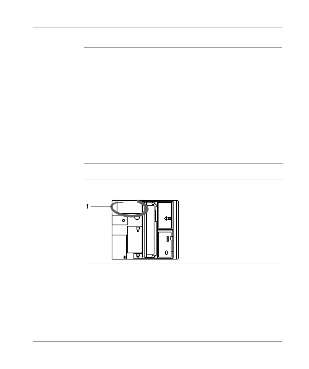
General points
The display block 1 centralizes all the information needed for diagnostics and for
maintenance of the PLC and its modules. For this, it provides the following:
8 LED status displays giving PLC operating information ( RUN, TER, I/O, ERR
and BAT LEDs) and the current display mode (R, I/O, WRD and DIAG LEDs),
from a block of 96 LED displays making it possible to display:
local inputs/outputs in display mode (BASE LED on): the state of all
discrete inputs and outputs of the PLC,
in diagnostic mode (DIAG LEDs on):
"module" errors (all LEDs associated with the module flash slowly),
"channel" errors (LED display associated with the channel),
in object display mode (WRD LED on): the contents of a maximum of 16
%MWi, %SWi, or %KWi words (these words are displayed in binary or
hexadecimal), the state of a group of 64 %Mi, %Si or %Xi bits,
a push button which enables the information sequence to be viewed and to
change the display mode.
Note: For further information concerning the display block, please refer to
theDisplay panel, p. 149
Illustration
display panel:
56
TSX DM 37 xxE

TSX 37-10PLC
7
At a Glance
Aim of this
This chapter is about the TSX 37-10 PLC, its physical description and its technical
Chapter
characteristics.
What's in this
This Chapter contains the following Maps:
Chapter?
Topic
Page
Introduction to the TSX 37 -10 PLC base
58
TSX 37-10: description
60
Characteristics of the TSX 37-10
61
TSX 37-10 display block
62
TSX DM 37 xxE
57

TSX 37-10 PLC
Introduction to the TSX 37 -10 PLC base
General points
A TSX 37-10 PLC base groups under one product reference:
a rack comprising the supply to the base (24 VDC or 100-240 VAC), the
processor, the dedicated memory, the backup memory in FLASH EPROM and
two slots for the modules,
a discrete module of 28 or 64 standard size inputs/outputs in the first slot in the
rack.
Table of the different types of TSX 37 10 base:
Base
Supply
Built-in input/output module
TSX3710028AR1
100240V AC
TSXDMZ28AR:16 115V AC inputs,
12 relay outputs
TSX3710028DR1
100240V AC
TSX DMZ 28DR: 16 24V DC inputs,
12 relay outputs
TSX3710128DR1
24V DC
TSX DMZ 28DR: 16 24V DC inputs,
12 relay outputs
TSX3710128DT1
24V DC
TSXDMZ28DT: 16 24V DC inputs, 12
static outputs
TSX3710128DTK1
24V DC
TSXDMZ28DTK: 16 24V DC inputs,
12 static outputs
TSX3710164DTK1
24V DC
TSX DMZ 64 DTK: 32 24V DC inputs,
32 static outputs
Using the TSX RKY 02 mini extension rack means 2 extra slots can be added to the
PLC. The package allows the use of 3 slots which can each be equipped with a
standard format module or two half-format modules.
58
TSX DM 37 xxE
TSX 37-10 PLC
Catalog data
the following table gives the maximum configurations of the TSX 37 10 PLCs:
Discrete inputs/outputs
Maximum number of discrete I/Os
in the base
128
in the base and extension
192
in the base + extension + remote (I/
268
O TSX 07)
in the base + extension + remote
408
(AS-i bus)
remote (4 TSX 07)
96
remote on the AS-i bus (124I +
248
124O)
Maximum number of modules
28 or 32 discrete inputs/outputs
4
64 discrete inputs/outputs (high
2
density)
input/output mismatch (for TSX 07 I/
1
O or AS-i bus)
Analog
Number of analog input/output modules
2
No. of analog inputs
16
No. of analog outputs
8
Counting
No. of 500Hz counting channels on discrete inputs
2
No. of counting modules (in the PLC)(*)
2
No. of 40kHz or 500kHz counting channels
4
(*) The counting modules are only to be installed in the basic PLC model.
A TSX 37-10 configuration can receive 2 analog modules and 2 counting modules.
RS 485 terminal
With an 8-point mini-DIN size RS 485 terminal port, it is possible to:
port
connect an FTX type terminal or a compatible PC, a printer,
and to connect the PLC to the UNI-TELWAY or Modbus busses. For this, it
proposes, by default, the UNI-TELWAY 96 Baud master communication mode
and, by configuration (see Communication incorporated in the bases, p. 307:
the UNI-TELWAY slave mode or,
ASCII character mode or,
the Modbus protocol.
Note: The terminal and PLC can both be connected to the UNI-TELWAY bus using the TSX P ACC 01
insulating device. This should be used when the distance between the UNI-TELWAY connection
equipment is greater than 10 meters (see TSX unit P ACC 01, p. 345).
TSX DM 37 xxE
59
TSX 37-10 PLC
TSX 37-10: description
Illustration
TSX 37-10:
Number table
function description of the numbers:
Number
Description
1
2 slot rack comprising the supply, the processor and its memory.
2
Fixing hole for the PLC.
3
Centralized display panel.
4
Terminal port (TER).
5
RESET button.
6
Access door to the supply terminals.
7
Stack change information label.
8
Access door to the optional stack and data protection switch for the operating system.
9
A 28 or 64 I/O module whose basic position is in the first slot.
10
Access cover to the connection connector of the mini extension rack.
11
Mounting device on DIN mounting rail.
Note: For an IP20 protection index, place the protection covers in the empty slots. These covers, which
are not supplied, should be ordered separately in batches, quoting the reference TSX RKA 01.
60
TSX DM 37 xxE

TSX 37-10 PLC
Characteristics of the TSX 37-10
Table of
Technical characteristics:
characteristics
PLCs
TSX 37-10
Functions
No. of discrete input/output
TSX 07 local + remote
268
local + remote on the AS-i bus
408
No. of connections
1
Built-in UNI-TELWAY
Communication modules
0
Real-time clock
Yes
Integrated analog
No
Integrated upcounting
On discrete inputs (-500 Hz)
Yes
-10 kHz
No
Internal memory
Savable internal RAM
14 Kwords
program (100% Boolean) (1)
4.7/2.7 Kinst.
data (in internal RAM)
1 Kword (2)
constant
128 words (2)
Built-in Flash Eprom
16 Kwords (3)
Memory extension
PCMCIA card
No
Execution time by
RAM (100% Boolean)
0.3ms
Kinst.(5)
PCMCIA (100% Boolean)
-
System overhead
1.9 ms
Application structure
Master task
1
Fast task
1
Task on events
1 to 8
Pre-defined function
Timers
64
(4)
blocks
Counters
32
(1) The first value corresponds to a program in List. The
2nd value corresponds to
a program in Ladder language.
(2) Size by default; can be extended at the expense of the application program size.
(3) 15 Kwords available for the backup application + 1 Kword for the %MW backup.
(4) A maximum of 16 timers, with a 10ms time base.
(5) Inoperative overhead and I/O management.
TSX DM 37 xxE
61
TSX 37-10 PLC
TSX 37-10 display block
General points
The display block 1 centralizes all the information needed for diagnostics and for
maintenance of the PLC and its modules. For this, it provides the following:
8 status LEDs giving PLC operating information (the RUN, TER, I/O, ERR and
BAT LEDs) and current display mode (the R I/O, WRD and DIAG LEDs),
from a block of 96 LED displays making it possible to display:
local inputs/outputs in display mode (BASE or EXT LED on) : the status of
all discrete PLC inputs and outputs and the mini extension rack,
remote inputs/outputs in display mode (R I/O LED lit) : the discrete input/
output status of each slave present on the AS-i bus,
in diagnostic mode (DIAG LEDs on):
"module" errors (all LEDs associated with the module flash slowly),
or
"channel" errors (LED display associated with the channel),
for remote inputs/outputs on the AS-i bus : the state of each slave (slaves with
error flashing),
in object display mode (WRD LED on): the contents of a maximum of 16
%MWi, %SWi or %KWi words (displayed in binary or hexadecimal mode), the
status of a group of 64 %Mi, %Si or %Xi bits, the status of the TSX 07 module
input and output bits used as discrete remote inputs/outputs,
a push button which enables the information sequence to be viewed and to
change the display mode.
Note: For further information concerning the display block, please refer to
theDisplay panel, p. 149
Illustration
display panel:
62
TSX DM 37 xxE

TSX 37-21 and TSX 37-22 PLCs
8
At a Glance
Aim of this
This chapter is about the TSX 37-21 and TSX 37-22 PLCs, their physical description
Chapter
and their technical characteristics.
What's in this
This Chapter contains the following Maps:
Chapter?
Topic
Page
Introduction to the TSX 37-21 and TSX 37-22 PLC bases
64
TSX 37-21 and TSX 37-22: description
66
Characteristics of the TSX 37-21 and the TSX 37-22
68
TSX 37-21 and TSX 37-22 display panel
70
TSX DM 37 xxE
63
TSX 37-21 and TSX 37-22 PLCs
Introduction to the TSX 37-21 and TSX 37-22 PLC bases
General points
The TSX 37-21 and TSX 37-22 PLC bases consist of a rack containing the 24V DC
supply (TSX 37-21 101 and TSX 37-22 101) or 100-240V AC supply (TSX 37-21 and
TSX 37-22 001), the processor, the dedicated memory, the backup memory and 3
module slots.
Using the TSX RKZ 02 mini extension rack means 2 extra slots can be added to the
PLC. The group makes 5 slots are available which can each be equipped with a
standard size module or two half-size modules, except for the first slot which can
only receive standard size modules.
A memory extension card and a communication module can be received using two
PCMCIA size slots.
Analog and built-in counting functions can also be accessed using 3 connectors
provided by the TSX 37-22 PLC.
Catalog data
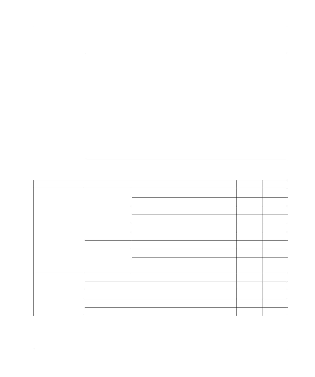
The following table gives the maximum configurations for the TSX 37-21 and TSX
37-22 PLCs (maximum number of modules and inputs/outputs):
PLC
TSX
37-21
37-22
I/O
Maximum number
in the base
192
192
of discrete I/Os
in the base+extension
256
256
in the base+extension+remotes (TSX 07)
332
332
in the base+extension+remotes (AS-i bus)
472
472
remote (4 TSX 07)
96
96
remote on the AS-i bus (124I+124O)
248
248
Maximum number
28 or 32 discrete inputs/outputs
5
5
of modules
64 discrete inputs/outputs (high density)
3
3
input/output mismatch (for TSX 07 I/O or AS-i
1
1
bus)
Analog
Maximum number of analog input/output modules
4
4
Maximum number of analog inputs in the rack
32
32
Maximum number of analog outputs in the rack
16
16
Maximum number of built-in analog inputs in the rack
-
8
Maximum number of built-in analog output
-
1
64
TSX DM 37 xxE
TSX 37-21 and TSX 37-22 PLCs
PLC
TSX
37-21
37-22
Counting
Maximum number of 500Hz counting channels on discrete inputs
2
2
Maximum number of counting modules (in the PLC) (1)
4
4
Maximum number of 40kHz and/or 500kHz counting channels
7
7
Maximum number of built-in counting channels (10 kHz)
-
2
Communication
Number of communication modules (2)
1
1
(1) The counting modules can only be installed in the basic PLC model.
A TSX 37-21/22 configuration can receive 4 analog modules and 4 counting
modules.
(2) PCMCIA communication card (FIPWAY, FIPIO Agent, Modbus+ Modem).
RS 485 terminal
Using two RS 485 terminal ports in 8 point mini-DIN size, it is possible to connect:
port
TER: an FTX type terminal or compatible PC, or to connect the PLC to the UNI-
TELWAY bus or Modbus via the TSX P ACC 01 insulating device,
AUX: an operator dialog terminal, or a printer.
For this, the terminal port and dialog operator port propose by default the UNI-
TELWAY master 96 Baud communication mode and, by configuration (see
Communication incorporated in the bases, p. 307:
the UNI-TELWAY slave mode or,
ASCII character mode or,
the Modbus protocol.
TSX DM 37 xxE
65
TSX 37-21 and TSX 37-22 PLCs
TSX 37-21 and TSX 37-22: description
Illustration
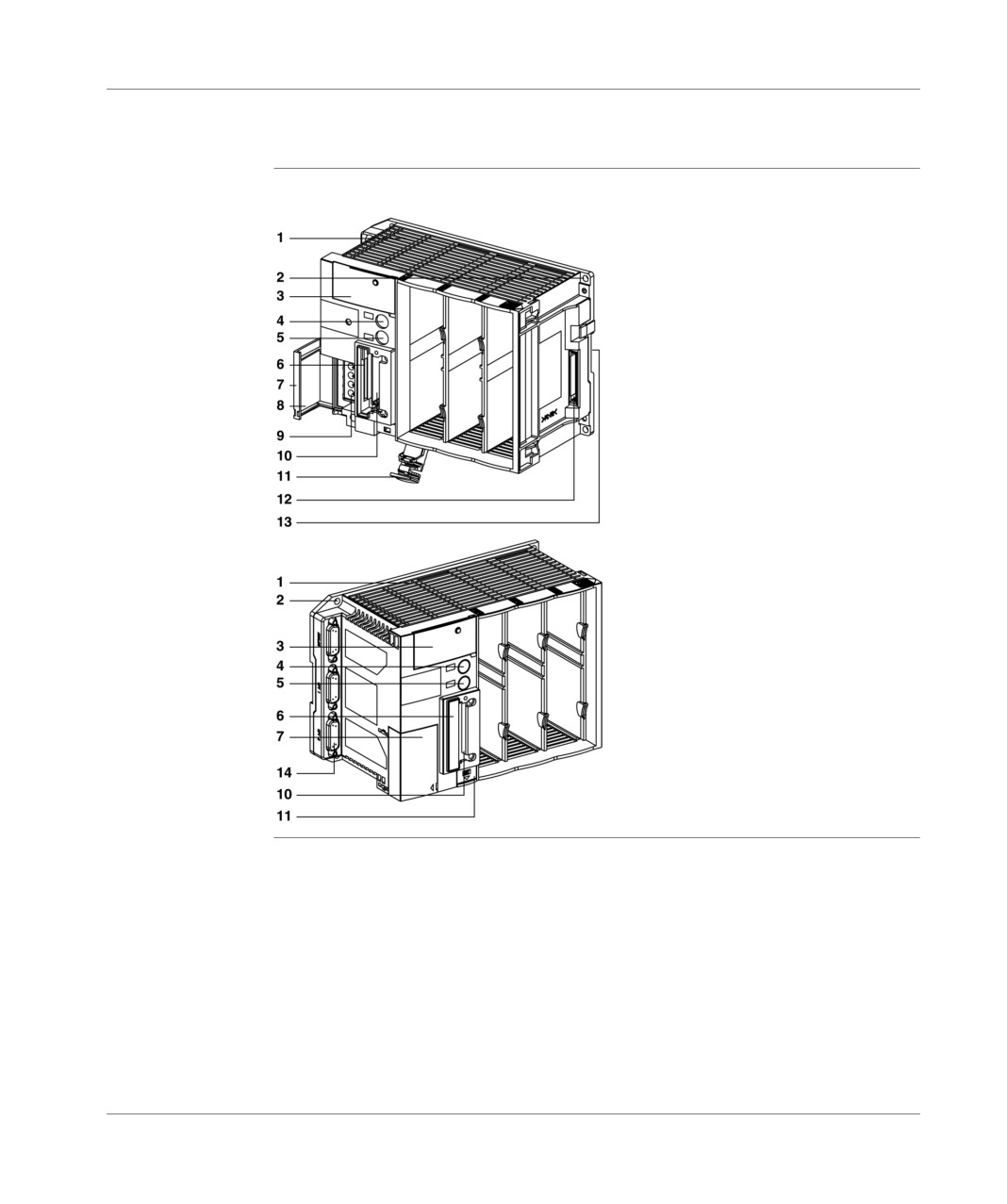
TSX 37-21 and TSX 37-22:
TSX 37-21
TSX 37-22
66
TSX DM 37 xxE

TSX 37-21 and TSX 37-22 PLCs
Address table
description for each address:
Address
Description
1
3 slot rack containing the supply, the processor and its base memory.
2
PLC fixing hole.
3
Centralized display block.
4
Terminal port TER.
5
AUX operator dialog port.
6
Slot for a memory extension card. If there is no card, this slot is equipped with
a cover which must be left in place as removing it will cause:.
• the PLC to stop,
• the terminal port to be inactive.
7
Access door to the supply terminals.
8
Battery change information label.
9
Supply terminals.
10
Slot for a communication module..
11
Access door to the optional battery and to the operating system data protection
switch.
12
Mini extension rack connector, fully protected by a removable cover.
13
Mounting device on DIN mounting rail.
14
Connectors for built-in analog and counting functions.
Note: For an IP20 protection rating, place protection covers in the empty slots.
These covers, which are not supplied, should be ordered separately in lots of 10,
quoting the reference TSX RKA 01.
TSX DM 37 xxE
67
TSX 37-21 and TSX 37-22 PLCs
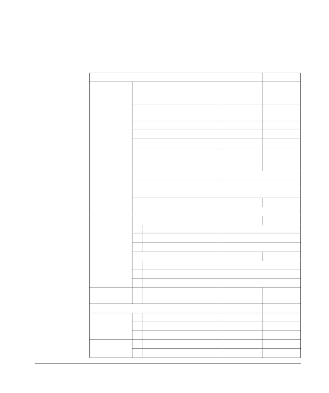
Characteristics of the TSX 37-21 and the TSX 37-22
Table of
Technical characteristics:
characteristics
PLCs
TSX 37-21
TSX 37-22
Functions
No. of discrete input/output
TSX 07 local + remote
332
332
local + remote on the AS-i bus
472
472
No. of connections
1
1
Built-in UNI-TELWAY
Communication modules
1
1
Real-time clock
Yes
Yes
Integrated analog
No
Yes
Integrated upcounting
-500 Hz
Yes
Yes
-10 kHz
No
Yes
Internal memory
Savable internal RAM
20 Kwords
program (100% Boolean) (1)
7.9/4.5 Kinst.
data (in internal RAM)
2 Kwords (2)
constant
128 words (2)
128 words (2)
Built-in Flash Eprom
16 Kwords (3)
Memory
32 K16 PCMCIA card
32 Kwords
32 Kwords
extension
program (100% Boolean) (1)
18.5/10.5 Kinst.
data (in internal RAM)
17.5 Kwords
constants (4)
256 words (2)
64 K 16 PCMCIA card
64 Kwords
64 Kwords
program (100% Boolean) (1)
40/22 Kinst.
data (in internal RAM)
17.5 Kwords
constants (5)
512 words (2)
Execution time
RAM (100% Boolean)
0.15 ms
0.15 ms
by Kinst.(7)
PCMCIA (100% Boolean)
0.225 ms
0.225 ms
System overhead
1.6 ms
2.3 ms
Application
Master task
1
1
structure
Fast task
1
1
Task on events
1 to 16
1 to 16
Pre-defined
Timers
64
(6)
64
(6)
function blocks
Counters
32
32
68
TSX DM 37 xxE
TSX 37-21 and TSX 37-22 PLCs
(1) The first value corresponds to a program in List. The 2nd value corresponds to
a program in Ladder language.
(2) Size by default; can be extended at the expense of the application program size.
(3) 15 Kwords available for the backup application + 1 Kword for the %MW backup.
(4) Can be extended to 24.5 Kwords.
(5) Can be extended to 32 Kwords.
(6) A maximum of 16 timers, with a 10ms time base.
(7) Inoperative overhead and I/O management.
TSX DM 37 xxE
69
TSX 37-21 and TSX 37-22 PLCs
TSX 37-21 and TSX 37-22 display panel
General points
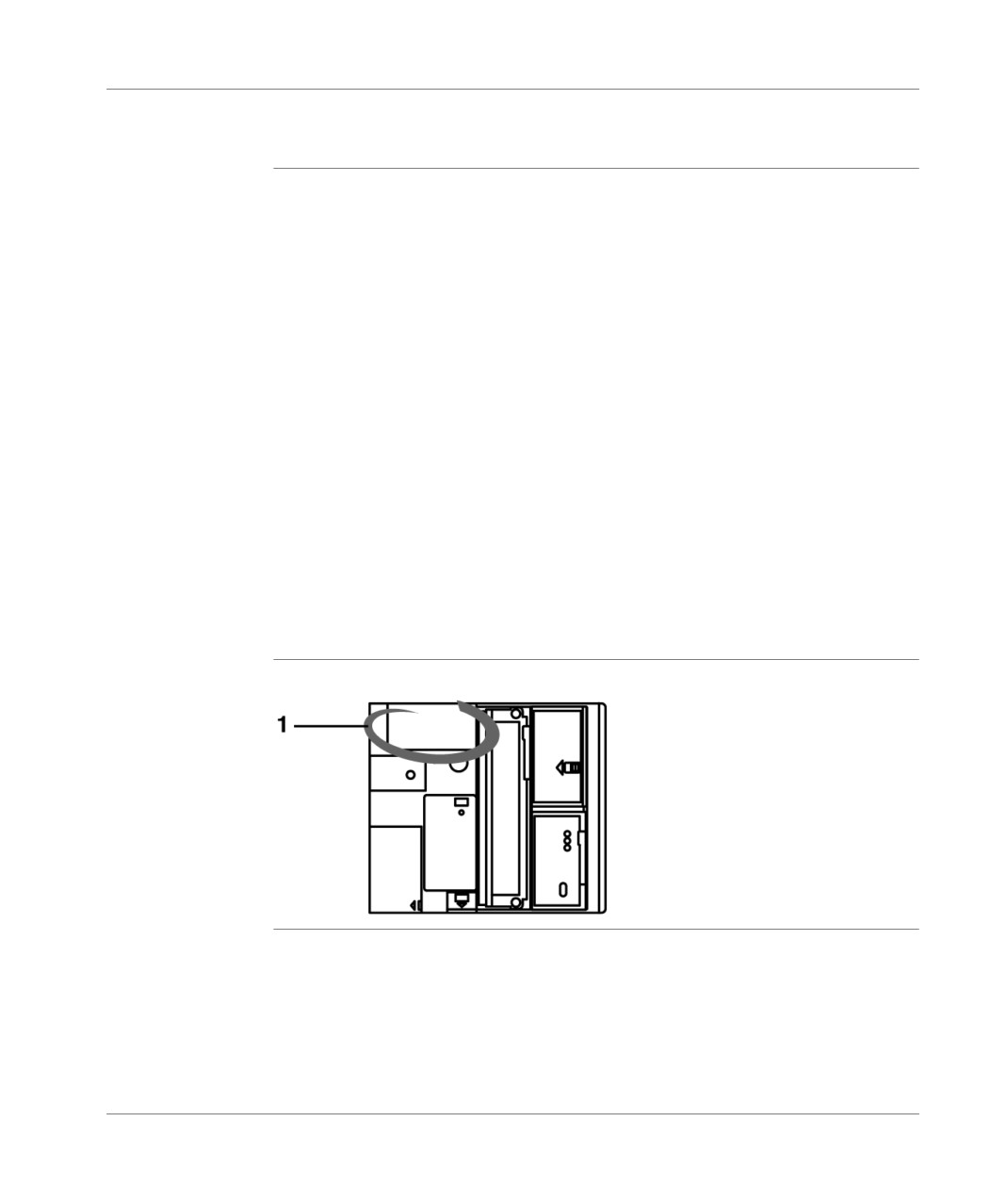
The display block 1 centralizes all the information needed for diagnostics and for
maintenance of the PLC and its modules. For this, it provides the following:
8 status LEDs giving PLC operating information (the RUN, TER, I/O, ERR and
BAT LEDs) and current display mode (the R I/O, WRD and DIAG LEDs),
from a block of 96 LED displays making it possible to display:
local inputs/outputs in display mode (BASE or EXT LED on): the status of
all discrete PLC inputs and outputs and the mini extension rack,
remote inputs/outputs in display mode (R I/O LED lit): the discrete input/
output status of each slave present on the AS-i bus,
in diagnostic mode (DIAG LEDs on):
"module" errors (all LEDs associated with the module flash slowly),
or
"channel" errors (LED display associated with the channel),
for remote inputs/outputs on the AS-i bus: the state of each slave (slaves with
error flashing),
in object display mode (WRD LED on): the contents of a maximum of 16
%MWi, %SWi or %KWi words (displayed in binary or hexadecimal mode), the
status of a group of 64 %Mi, %Si or %Xi bits, the status of the TSX 07 module
input and output bits used as discrete remote inputs/outputs,
a push button which enables the information sequence to be viewed and to
change the display mode.
Illustration
display panel:
70
TSX DM 37 xxE

TSX 37 PLC supplies
9
At a Glance
Aim of this
This chapter is about the TSX 37 PLC base supplies.
Chapter
What's in this
This Chapter contains the following Maps:
Chapter?
Topic
Page
Alternating current supplies
72
Direct current supply
73
Additional characteristics
74
TSX DM 37 xxE
71
TSX 37 PLCs supplies
Alternating current supplies
Characteristics
table of characteristics:
PLCs
TSX 37-05/08/10/21/22
Primary
Nominal voltages
100…240 VAC
Voltage limits
85-264 VAC
Nominal frequencies
50-60 Hz
Frequency limits
47-63 Hz
Current absorbed
0.7 A to 100 V
0.3 A to 240 V
Call current (2)
< 60 A
Secondary
+5 VDC
Nominal current
2.8 A
(1)
Peak current
3.2 A
+24 V relay
Nominal current
0.5 A
(1)
Peak current
0.6 A
+24V sensors (3)
Nominal current
0.4 A
(1)
Peak current
0.6 A
Total power (4)
Nominal
24 W
Peak
32 W
Insulation
Dielectric strength:
primary/
2500 V eff
secondary
50/60 Hz
(1) The nominal currents correspond to the consumption of 2/3 of the active inputs/
outputs simultaneously. The supply can nevertheless operate without cutting off
peak power equivalent 100% of the active inputs/outputs simultaneously.
(2) This value means that the network should support a call current of 60 A. It should
be taken into account when starting several devices simultaneously or for
dimensioning protection devices.
(3) For an alternating supply, the 24 V sensor limits the configuration to 100 inputs
on the base. Beyond this, an external supply must be used.
(4) The total power is not the sum of the power equivalent to the maximum yield of
each of the outputs that it is possible to obtain simultaneously in one configuration.
It is calculated for particular configurations, which correspond to optimum usage of
the PLC.
72
TSX DM 37 xxE
TSX 37 PLCs supplies
Direct current supply
Characteristics
table of characteristics:
PLCs
TSX 37-10/21/22
Primary
Nominal voltages
24 VDC
Voltage limits (ripple included)
19-30 VDC
19-34 VDC (3)
Peak to peak ripple
5% of Un F = 90
Hz to 1 kHz
Frequency limits
47-63 Hz
Current absorbed
2A
Maximum call current (2)
< 60 A
Secondary
+5 VDC
Nominal current
2.8 A
(1)
Peak current
3.2 A
Total power (4)
Nominal
16 W
Peak
18 W
Insulation
Dielectric strength:
primary/
No insulation; the
secondary
0V and PE are
internally coupled
(1) The nominal currents correspond to the consumption of 2/3 of the simultaneously
active inputs/outputs. The supply can nevertheless operate without cutting off a
peak power matching 100% of the simultaneously active inputs/outputs.
(2) This value means that the network should support a call current of 60 A. It should
be taken into account when starting several devices simultaneously or for
dimensioning of protection devices.
(3) 34 VDC for one hour, for a battery operated device with charger.
(4) The total power is not the sum of the power matching the maximum yield of each
of the outputs that it is possible to obtain simultaneously in one configuration. It is
calculated for particular configurations, which correspond to optimum usage of the
PLC.
TSX DM 37 xxE
73
TSX 37 PLCs supplies
Additional characteristics
Supply
The supply provided by the TSX 37-05/08, TSX 37-10, TSX 37-21 and TSX 37-22
protection
PLCs are all protected against overloading and short circuits.
A short circuit or overload on the 24 V sensor does not have any effect on the other
voltages. The 24 V sensor reappears when the error disappears.
Service signals
During operation, a signal is generated when the PLC supply voltage exceeds the
limits (Power Fail).
Programming
The +5 VDC voltage, delivered by PLC to the terminal port, does not allow auto-
terminal supply
supply of a programming terminal, but a pocket terminal with a very low power
consumption (<200 mA).
74
TSX DM 37 xxE

Memories on TSX 37
10
At a Glance
Aim of this
This chapter describes the memory on TSX 37.
chapter
What's in this
This Chapter contains the following Maps:
Chapter?
Topic
Page
Internal memory
76
PCMCIA memory extension cards on TSX 37-21/22 PLCs
77
Standard and Backup memory cards
79
Application + file type memory cards
80
TSX DM 37 xxE
75
Memories on TSX 37
Internal memory
General points
The internal memory store of the TSX 37-05/08/10/21/22 PLCs is composed of two
separate stores :
An internal RAM memory (1), which is used by the application program and which
has a capacity of :
9 Kwords for a TSX 37-05/08 PLC
14 Kwords for a TSX 37-10 PLC
20 Kwords for a TSX 37-21/22 PLC.
Furthermore, in the case of a TSX 37-21/22 PLC, the application memory can be
extended with a 32 or 64 Kword PCMCIA memory card, of the RAM or FLASH
EPROM type.
A FLASH EPROM memory of:
10 Kwords on the TSX 37-05/08 PLCs,
16 Kwords on the TSX 37-10/21/22 PLCs, which is a backup memory.
This memory is a backup memory:
- of the application program (only 15 Kwords can be used as a backup for the
application program on the TSX 37- 21/22 PLCs),
- of the %MW internal words with a maximum of 1000 internal words (store
reserved for 1 Kword).
(1) The internal RAM memory is backed up by an optional 3.6V battery with an
autonomy of 2 years (see Inserting/changing the battery, p. 110).
Note: In some cases, (configuration error, application change), it may be useful to
totally erase the contents of the internal RAM or FLASH EPROM of the PLC. For
this, carry out the PLC power-up keeping the DIAG button pressed during the
running of the autotests (a minimum of 10 seconds).
76
TSX DM 37 xxE
Memories on TSX 37
PCMCIA memory extension cards on TSX 37-21/22 PLCs
General points
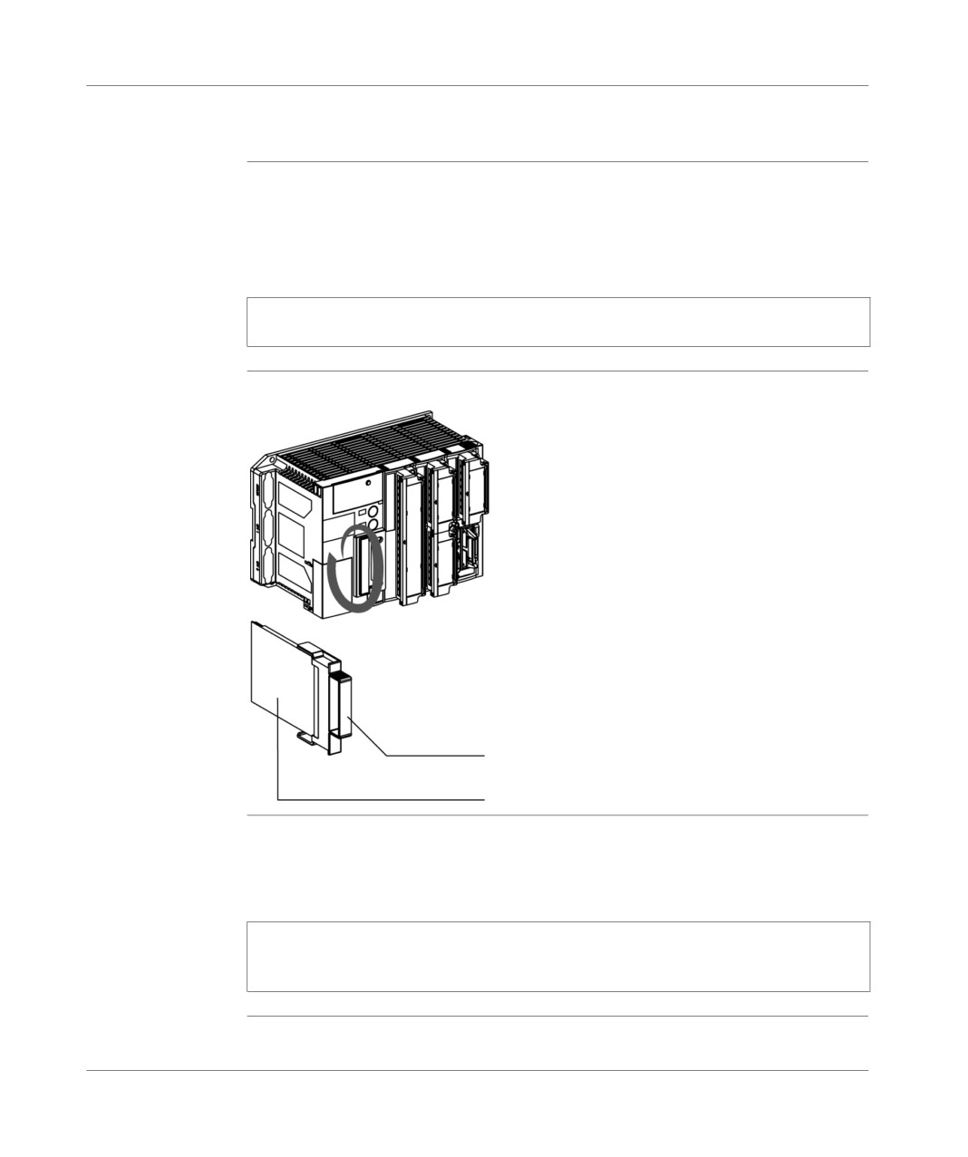
The slot on the front panel of the PLC, which is protected by a cover, is for the
insertion of an optional memory card of the PCMCIA type 1 format. This card
extends the internal memory of the processor to store the application program and
its constants.
Note: the protective cover must be removed before the PCMCIA card can be
inserted.
Illustration
PCMCIA card and TSX 37:
Handle
PCMCIA memory card
Handling
A PCMCIA memory card can be inserted or removed when switched on.. So that it
PCMCIA memory
is operational, the memory card should be equipped with a handle, the absence of
cards when
which disables the starting of the processor (processor failed, led ERR lit).
switched on
Note: If the program contained in the PCMCIA memory card includes the RUN
AUTO option, the processor will automatically restart in RUN after the card is
inserted.
TSX DM 37 xxE
77
Memories on TSX 37
Protection of the PMCIA cards are equipped with a lockout system which forbids write access
application
(loading of a new program)
This protection comes in addition to the software protection (see PL7 online help)
which forbids read access to the program.
78
TSX DM 37 xxE
Memories on TSX 37
Standard and Backup memory cards
Standard
There are different types of standard memory cards:
memory cards
backup RAM type memory extension card:
used in particular during the creation phases and when debugging the application
program, it allows all the applications transfer and modification services in
connected mode; the memory is backed up by a built-in removable stack in the
memory card,
FLASH EPROM type memory extension card:
used when the application program debugging has ended, it allows only a global
transfer of the application, and to avoid stack backup problems.
BACKUP type
Previously loaded with the application program, it reloads the program into the
memory cards
processor’s internal RAM memory without the need to use a programming terminal.
This card can only be used in cases where the application is only in the processor’s
internal RAM memory and if the entire size (program + constants) is less than 15
Kwords.
Standard and
Reference table:
backup type
References
Type/capacity
PLC compatibility
memory card
TSX 37-05
TSX 37-21
references
TSX 37-08
TSX 37-22
TSX 37-10
TSX MRP 032 P
RAM/32 K16
No
Yes
TSX MRP 064 P
RAM/64 K16
No
Yes
TSX MFP 032P
Flash Eprom/32 K16
No
Yes
TSX MFP 064P
Flash Eprom/64 K16
No
Yes
TSX MFP BA032P
BACKUP/32 K 16
No
Yes
Note: Memory capacity: K16 = Kwords (16-bit word).
TSX DM 37 xxE
79
Memories on TSX 37
Application + file type memory cards
General points
These memory cards, as well as a traditional application storage area, also have:
a file zone allowing data to be archived by program.
Application examples:
automatic storage of application data and remote consultation by modem link,
storage of manufacturing formulas,
etc
There are two types of memory card:
saved RAM type application memory extension card + files. The memory is
saved by a removable battery built into the memory card,
Flash Eprom type application memory extension card + saved RAM type file
zone. This file zone is saved by a removable battery built into the memory
card.
Application + file
Reference table:
type memory
References
Type/capacity
PLC compatibility
card references
Application zone
File zone
TSX 37-05
TSX 37-21
(RAM type)
TSX 37-08
TSX 37-22
TSX 37-10
TSX MRP 232P
RAM/32 K 16
128 K 16
No
Yes
TSX MRP 264P
RAM/64 K 16
128 K 16
No
Yes
TSX MRP 232P
Flash Eprom/32
128 K 16
No
Yes
K 16
TSX MRP 264P
Flash Eprom/64
128 K 16
No
Yes
K 16
80
TSX DM 37 xxE
Mini extention rack
11
Mini extension rack
At a Glance
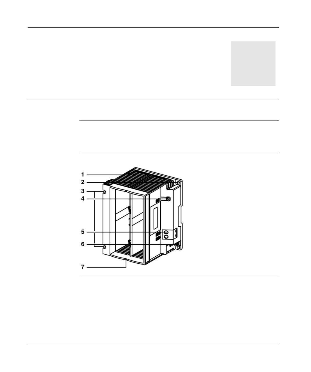
The mini extension rack TSX RKZ 02 allows two slots to be added to a TSX 37-10/
21/22 PLC base; each of which can receive one module in standard format or two
modules in semi-format.
Physical
The illustration below shows the mini extension rack.
Description
TSX DM 37 xxF
81

Mini extention rack
Information
description for each of the numbers:
Table
Number
Description
1
Extension rack with 2 slots.
2
Fixing hole of the extension rack.
3
Fixing screw of the base extension.
4
LED showing that auxiliary voltage of 24 VDC is being supplied (for relay or
analog modules).
5
Supply terminals protected by a removable cover.
6
Ground connection terminals.
7
PLC base connectors (backplane bus and ground continuity).
Note: For an IP20 protection rating, place the protection covers in the empty slots.
These covers, which are not supplied, should be ordered separately in lots of 10,
quoting the reference TSX RKA 01.
Supply
When the TSX 37-10/21/22 PLC is supplied from an alternating network, the 24 VDC
is not supplied to the mini extension rack. In this case, if the relay or analog modules
are present in the extension, a 24 VDC auxiliary supply must be connected to the
supply terminals of the mini extension rack (refer to the paragraph "Supply
connections").
The 24 V voltage supplied by the base allows the sensors to be supplied and
possibly those in the extension, on the condition that the consumption balance does
not exceed 400 mA. If this is not the case, also use a 24 VDC auxiliary supply.
82
TSX DM37 xxF