TSX Micro PLCs TSX 3705/3708/3710/3720. Implementation Manual (Volume 1) - page 1
TSX Micro PLCs
TSX 3705/3708/3710/3720
Implementation Manual Volume 1
TSX DM 37 xx eng
Related Documentation
Related Documentation
At a Glance
This manual comprises three volumes.
Volume 1,
Processors,
Implementation/Diagnostics/Maintenance,
Integrated analog,
Integrated upcounting,
Integrated communication.
Volume 2,
Discrete input/output modules,
Remote adaptor modules for discrete input/outputs,
Process and AS-i supplies.
Volume 3.
Analog input/output modules,
Counting module,
Communication by PCMCIA card.
TSX DM 37 xxE
3
Table of Contents
About the book
13
Part I
General introduction to a PLC station
15
At a Glance
15
Chapter
1
General introduction to TSX Micro PLCs
17
TSX Micro PLCs
17
Chapter
2
General introduction to the components of a PLC station. . .19
At a Glance
19
General information about discrete inputs/outputs
20
Local discrete inputs/outputs in the rack
21
Remote discrete inputs/outputs
22
Discrete safety inputs/outputs
24
Local analog inputs/outputs
25
Remote analog inputs/outputs
27
Counting channel
28
Forced PLC ventilation
30
Chapter
3
General introduction to communication
31
At a Glance
31
Communication
32
UNI-TELWAY link
33
Character mode link by terminal port
34
Modbus Connection
35
FIPWAY link
36
FIPIO link
37
Modem link
38
Modbus Plus Link
39
Chapter
4
Addressing system
41
Channel address settings
41
Part II
TSX 37 PLC
43
At a Glance
43
5
Chapter
5
TSX 37-05 PLC
45
At a Glance
45
Introduction to the TSX 37 05 PLC base
46
TSX 37-05: physical description
48
Characteristics of the TSX 37-05
49
Display panel on TSX 37-05
50
Chapter
6
TSX 37-08PLC
51
At a Glance
51
Introduction to the TSX 37 -08 PLC base
52
TSX 37-08: physical description
54
Characteristics of the TSX 37-08
55
Display panel on TSX 37-08
56
Chapter
7
TSX 37-10PLC
57
At a Glance
57
Introduction to the TSX 37 -10 PLC base
58
TSX 37-10: description
60
Characteristics of the TSX 37-10
61
TSX 37-10 display block
62
Chapter
8
TSX 37-21 and TSX 37-22 PLCs
63
At a Glance
63
Introduction to the TSX 37-21 and TSX 37-22 PLC bases
64
TSX 37-21 and TSX 37-22: description
66
Characteristics of the TSX 37-21 and the TSX 37-22
68
TSX 37-21 and TSX 37-22 display panel
70
Chapter
9
TSX 37 PLC supplies
71
At a Glance
71
Alternating current supplies
72
Direct current supply
73
Additional characteristics
74
Chapter 10
Memories on TSX 37
75
At a Glance
75
Internal memory
76
PCMCIA memory extension cards on TSX 37-21/22 PLCs
77
Standard and Backup memory cards
79
Application + file type memory cards
80
Chapter 11
Mini extention rack
81
Mini extension rack
81
Chapter 12
TSX 37 PLC performance
85
Performances
85
6
Chapter 13
Commissioning standards and conditions
87
At a Glance
87
Standards and certifications
88
Operating conditions and environmental recommendations
89
Protection treatment for TSX 37 Micro PLCs
90
Part III
TSX 37 PLC: Mounting
95
At a Glance
95
Chapter
14
TSX 37 PLC: installation
97
At a Glance
97
Rules of installation
98
Dimensions
100
PLC mounting/fixing
101
Mounting the base onto a DIN profile (or rail)
102
Mounting the PLC onto a board or panel
103
Procedure for assembling the extension with the base
104
Inserting a module
106
Removing a module
108
Inserting/changing the battery
110
Mounting/removing the memory card
112
Changing the battery on the PCMCIA card
114
Screw tightening torque
116
Chapter
15
TSX 37 PLC: connection
117
At a Glance
117
Ground connection of the PLC
118
Grounding the modules
119
Supply connections
120
Connection rules
121
Connecting PLCs supplied with alternating current
122
Connecting several PLCs supplied by TBX SUP 10 or TSX SUP supplies
125
Connecting PLCs supplied with direct current
126
Connecting PLC(s) supplied by a continuous floating network (not grounded). 129
Specific provisions for a continuous floating network
131
Sensor and pre actuator supply control
132
Chapter
16
Ventilation module
135
At a Glance
135
Ventilation module: general introduction
136
Ventilation module: physical presentation
138
Ventilation module: catalog
139
Ventilation module: dimensions
140
Ventilation module: mounting
141
Rules for installation of the racks with ventilation modules
143
Ventilation module: connections
144
7
Ventilation module: characteristics
146
Part IV
Commissioning/Diagnostics/Maintenance
147
At a Glance
147
Chapter
17
Display panel
149
At a Glance
149
Introduction
150
PLC status display
152
Local input/output status display
154
64 channel modules display
156
Sequencing of the displays
158
Display of faulty local inputs/outputs
159
Display of remote inputs/outputs on the AS-i bus
161
Display of the presence of each slave on the AS-i bus (R I/O mode - DIAG) . . 162
Display of the status of the input/output bits for each slave (R I/O mode)
164
Incrementation of the slave number in ascending or descending order
166
Specific standard functions
167
Management of the battery LED (BAT)
168
Chapter
18
Display of language objects
169
At a Glance
169
WORD mode
170
Word of order and status : %SW67
171
Index word : %SW68
173
Word %SW69
175
Example : word display in hexadecimal mode
176
Example : word display in binary mode
178
Example : display of the internal bit status
181
Example: Display of remote inputs/outputs on TSX 07
183
Chapter
19
Commissioning
185
At a Glance
185
First power-up
186
Description of PLC states
188
Chapter
20
Maintenance
191
At a Glance
191
Researching the errors from PLC status monitors
192
Non-blocking faults
193
Blocking faults
195
Central processing unit (CPU) faults
197
Updating the Operating System
198
Part V
Analog incorporated in the bases
201
At a Glance
201
8
Chapter
21
Overview of the built-in analog interface
203
At a Glance
203
General
204
Functions
205
Characteristics of the built-in analog inputs
207
Built-in analog output feature
208
Chapter
22
Connecting the built in interface
209
At a Glance
209
Direct connection of the analog interface
210
Using the TELEFAST pre-wiring system
211
Connecting analog inputs with insulated or non-insulated sensors
213
Connecting analog output and external sliders
214
Connecting a variable speed controller
215
Details of wiring the ALTIVAR 16
216
ABE-7CPA01 analog TELEFAST internal wiring
218
Chapter
23
TSX ACZ 03 adjustment and adaptation module
219
At a Glance
219
TSX ACZ 03 adjustment and adaptation module: at a glance
220
Module standard functions
222
Module implementation
224
Selecting the function carried out by the module
227
Part VI
Counting built into bases
229
At a Glance
229
Chapter
24
Overview of built-in counting function
231
At a Glance
231
500Hz counts on the discrete inputs of TSX 37 bases
232
Built in 10 KHZ counting function on TSX 37 22 bases
233
Chapter
25
Overview of different counting functions
235
At a Glance
235
Down counting function
236
Up counting function
237
Up/down counting function
238
Chapter
26
Counting functions on (500Hz) discrete inputs
239
At a Glance
239
Introduction
240
Up counting or down counting
241
Up/down counting
243
Chapter
27
Up counting functions built in to (10KHz) TSX 37 22 bases.247
At a Glance
247
9
Introduction
248
Up or down counting
249
Up/down counting on channels 11 and 12
251
Up/down counting only on channel 11 (first possibility)
252
Up/down counting only on channel 11 (first possibility)
254
Up/down counting only on channel 11 (third possibility)
255
Preset on reference point short cam
257
Chapter
28
Implementing 500Hz up counting on discrete inputs
259
At a Glance
259
Basic configuration required
260
Types of sensor which can be used on up counting discrete inputs
262
Principal for connecting supplies and sensors
264
Example 1: up counting with inductive detector on the positive logic input
266
Example 2: upcounter with inductive detector on negative logic inputs
267
Example 3: upcounter with incremental encoder with Totem pole outputs
268
Example of sensor and supply cabling with TELEFAST 2 connection base: ABE-
7H16R20
269
General implementation rules
270
Chapter
29
Implementing 10KHz upcounter onto TSX 37-22 bases
271
At a Glance
271
Basic configuration required
272
Type of sensors which can be used on the upcounter inputs
273
Characteristics
274
Pin configuration of the 15-pin SUB-D (channels 11 and 12) connectors
276
Connecting an incremental encoder on channel 11
279
PLC/encoder connection
281
Connecting supply and preset sensor
284
Connecting counting sensors on channel 11 and 12
285
Connecting supplies and sensors on channel 11
286
Connecting supply and sensors on channel 12
287
General rules for implementation
288
Chapter
30
Appendices
291
At a Glance
291
TELEFAST 2 :ABE-7CPA01 connection base
292
Availability of the counting signals on the TELEFAST screw terminal block . . . 294
Matching TELEFAST terminal blocks and 15-pin SUB-D connector
296
TELEFAST 2 connection base: ABE-7H1•R••
298
Example: using the ABE-7H16R2 pre-wire base
299
Correspondence between TELEFAST terminal blocks and HE10 connector . . 300
Cabling accessories for incremental encoder: TSX TAP S15••
301
Mounting the TSX TAP S15 05/24
303
Connecting an encoder with a TSX TAP S15 05 accessory
305
Connecting an encoder with a TSX TAP S15 24 accessory
306
10
Part VII
Communication incorporated in the bases
307
Aim of this tab
307
Chapter 31
Terminal port
309
Overview of this chapter
309
31.1
Micro communication
310
At a Glance
310
Foreword
311
At a Glance
312
Communication with a terminal
314
Communication with an operator dialog console
315
Communication UNI-TELWAY master/slave
316
Communication character string
317
Communication Modbus/JBus
318
31.2
Connections
319
Introduction to this Section
319
Connections
320
Programming and adjustment terminal
322
Operator dialog console
323
Programming and adjustment terminal and operator dialog console
324
Modem on terminal port
326
UNI-TELWAY Master
328
UNI-TELWAY Slave
329
UNI-TELWAY intersection PLC’s
330
UNI-TELWAY intersection devices
332
Master PLC, model 40, type TSX
333
Character string
334
Modbus/JBus
335
Summary table
337
31.3
Attachments
340
Introduction to this Section
340
Properties of the terminal port
341
Connectors on the TSX 37 PLC
343
Chapter 32
TSX unit P ACC 01
345
Overview of this chapter
345
32.1
Hardware implementation
346
Introduction to this Section
346
Standard functions
347
External appearance
348
Dimensions and settings
349
Internal view
350
Connection to UNI-TELWAY or Modbus buses
351
Connection to TSX 37 PLCs
352
Switch configuration
353
32.2
Examples of topology
354
11
Introduction to this Section
354
Connectable devices
355
Master UNI-TELWAY mode
356
Slave UNI-TELWAY mode
357
Modbus/JBus
358
Connection between two PLCs
359
TSX P ACC 01 connectors
360
Index
361
12
About the book
At a Glance
Document Scope This manual describes implementation of TSX Micro PLCs.
User Comments We welcome your comments about this document. You can reach us by e-mail at
TECHCOMM@modicon.com
TSX DM 37 xxE
13
General introduction to a PLC
station
I
At a Glance
Aim of this Part
This part aims to provide a general description of a PLC station and its different
components.
What's in this
This Part contains the following Chapters:
part?
Chapter
Chaptername
Page
1
General introduction to TSX Micro PLCs
17
2
General introduction to the components of a PLC station
19
3
General introduction to communication
31
4
Addressing system
41
TSX DM 37 xxE
15
General introduction to a PLC station
16
TSX DM 37 xxE
General introduction to TSX Micro
PLCs
1
TSX Micro PLCs
Introduction
The range of TSX Micro PLCs comprises several PLC types, so as to best meet your
needs.
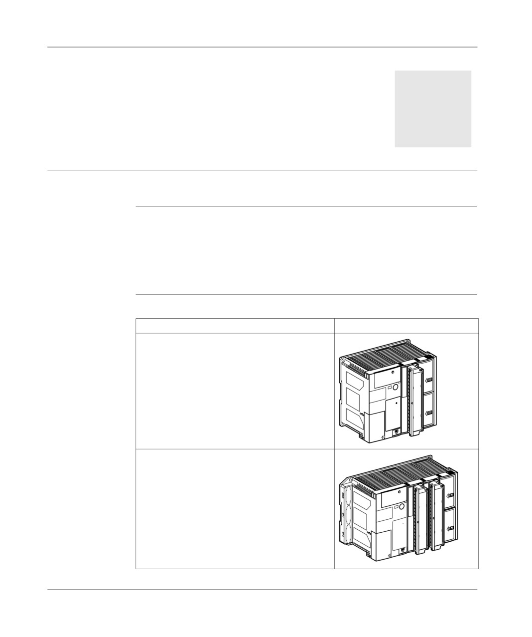
The TSX 37-05, TSX 37-08 and TSX 37-10 PLCs, at the same time modules that
are compact and capable of integrating one or two discrete input/output modules
into the database, according to the type,
the TSX 37-21 and TSX 37-22 modular PLCs.
TSX 37-05
The table below presents the TSX 37-05, TSX 37-08 and TSX 37-10 PLCs.
TSX37-08
Type
Illustration
TSX 37-10
the TSX 37-05PLC, incorporates a 28 input/output
(16I +12O)module in its database. This is located in
the first slot and has two available half slots which
enable either a standard format module, or two half-
format modules, to be received.
Its maximum input/output capacity is 92 discrete I/O,
with installation in the available slot of a 64 discrete I/
O module connected by an HE10 connector.
the TSX 37-08PLC, incorporates two 28 input/output
(16I +12O)modules in its database. These are
located in the first two slots and have two available
half slots which enable either a standard format
module, or two half-format modules, to be received.
Its maximum input/output capacity is 120 I/O with
installation in the available slot of a discrete 64 I/O
module (connected by an HE10 connector).
TSX DM 37 xxE
17
General introduction to TSX Micro PLCs
Type
Illustration
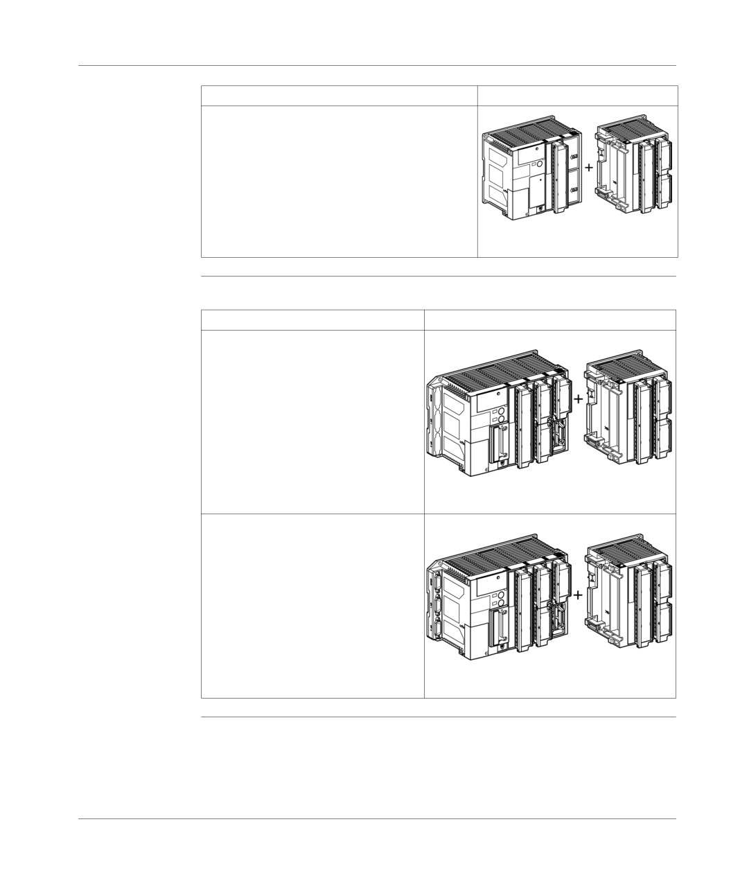
the TSX 37-10PLCs, offer five database
configurations. They differ in their supply voltage and
the discrete module type installed in the first slot.
These PLCs can receive a mini extension rack, which
allows the number of local inputs/outputs to be
extended to 192 I/O.
These PLCs are equipped with a real-time clock.
Base
extension
TSX 37-21
The table below presents the TSX 37-21 and TSX 37-22 PLCs.
TSX37-22
Type
Illustration
The TSX 37-21PLC is available in 2
configurations which differ according to
the power supply type.
These PLCs do not integrate discrete
input/output modules in the database.
They possess a maximum capacity of 256
I/O when a mini extension rack is added.
They are equipped with a real-time clock,
enabling the application memory volume
to be extended and can receive a
Base
extension
communication module.
the modular TSX 37-22 PLCs are identical
in every way to TSX 37-21 PLCs, with
further rapid counting and analog input/
output functions built in.
Base
extension
18
TSX DM 37 xxE

General introduction to the
components of a PLC station
2
At a Glance
Aim of this
This chapter aims to describe the main constituent elements of a TSX 37 PLC.
Chapter
What's in this
This Chapter contains the following Maps:
Chapter?
Topic
Page
General information about discrete inputs/outputs
20
Local discrete inputs/outputs in the rack
21
Remote discrete inputs/outputs
22
Discrete safety inputs/outputs
24
Local analog inputs/outputs
25
Remote analog inputs/outputs
27
Counting channel
28
Forced PLC ventilation
30
TSX DM 37 xxE
19
General introduction of the components of a PLC station
General information about discrete inputs/outputs
At a Glance
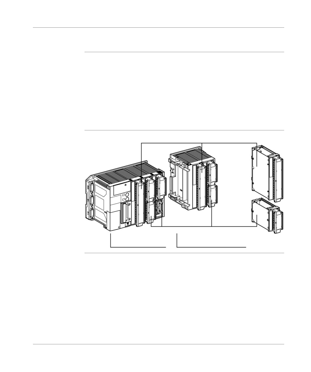
All discrete modules ( see TSX Micro Installation Manual, Volume 2 ) can be
installed in all the available positions in TSX 37 PLCs. In order to best meet your
requirements, two module sizes are on offer for the discrete inputs/outputs:
the standard size which takes up a slot (2 position),
the half-size which takes up a single position.
All the other modules (analog, counting, etc.) are half-size modules.
A mini extension rack, which can be directly connected to the PLC database,
enables the number of available slots to be extended and therefore the number of
modules, which can be used, to be increased.
Illustration
TSX Micro and discrete modules:
Module
with
standard
format
Module
with
half
format
PLC base
Mini extension rack
20
TSX DM 37 xxE
General introduction of the components of a PLC station
Local discrete inputs/outputs in the rack
General points
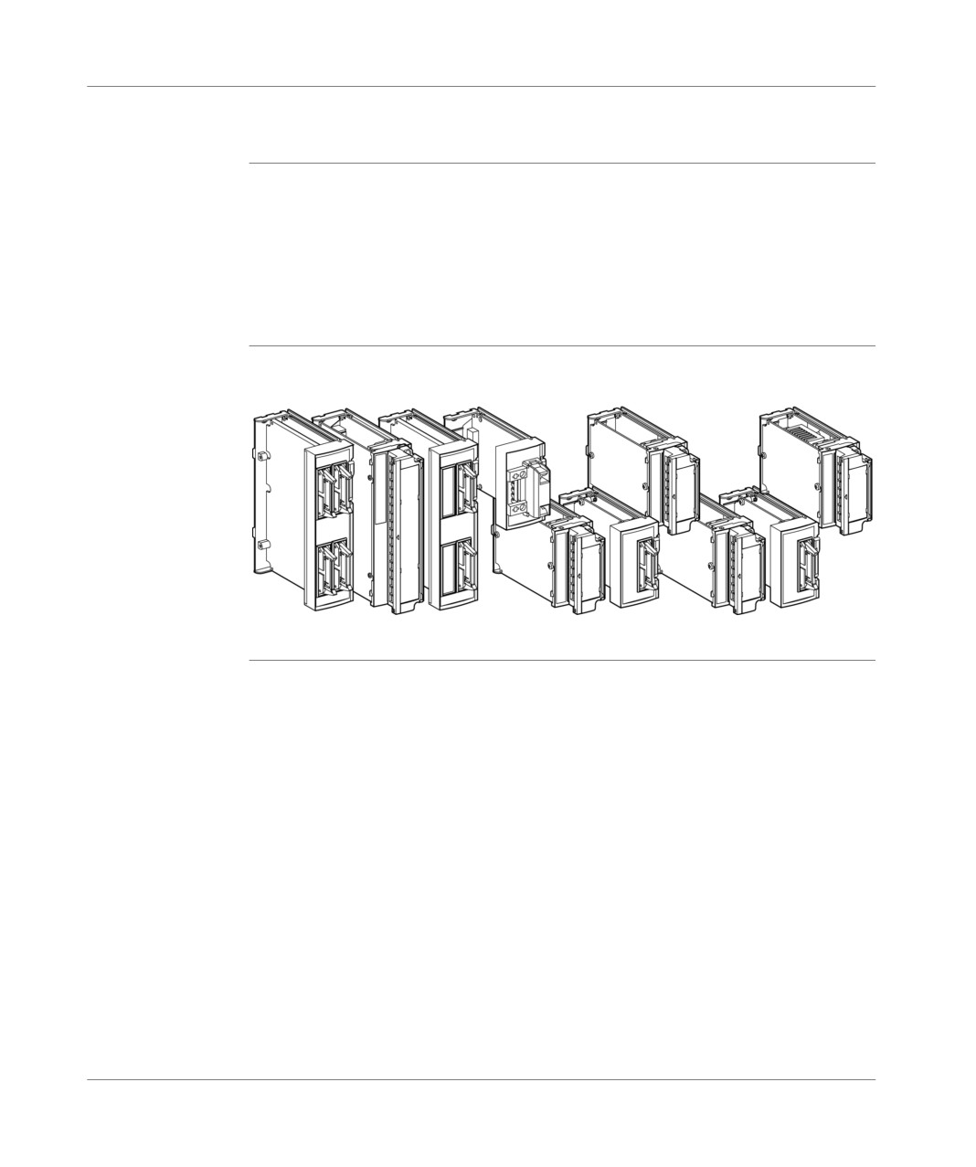
The discrete input/output modules differ in:
their format (standard and half-format),
their modularity (from 4S to 64I/O),
their channel types
direct current or alternative current inputs,
static or relay outputs,
their connector (HE10 screw terminal connector(s)).
Illustration
The illustration below presents the different types of local discrete input/output
modules in the rack.
64 I/O
32I/32O/28I/O
16 I/O
12 I
8I
8O
4S
TSX DM 37 xxE
21
General introduction of the components of a PLC station
Remote discrete inputs/outputs
Introduction
The TSX Micro range enables you to use remote discrete inputs/outputs (see
Implementation manual TSX Micro Volume 2)
For this, two modules are proposed:
an offset module TSX STZ 10,
a bus master module AS-i TSX SAZ 10 (only on TSX 37-10 and TSX 37-21/22).
Note: This choice is exclusive: it is not possible to us both modules simultaneously.
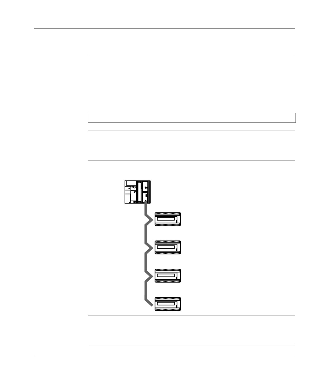
Using a TSX STZ The TSX STZ 10 offset module enables the inputs/outputs of 4 TSX 07-PLCs to be
10 offset module used remotely (up to 200m), and to thus increase the number of inputs/outputs in
the configuration.
Illustration
The schema below illustrates the connection between the TSK STZ 10 offset
module and TSK 07 PLCs
10 - 16 - 24 I/O
Bus Length:
10 - 16 - 24 I/O
200 m max.
10 - 16 - 24 I/O
10 - 16 - 24 I/O
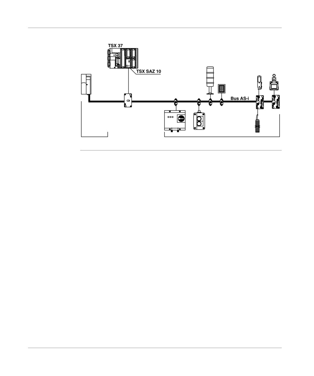
Using an AS-i
Using an AS-i interface module enables 124 input bits and 124 output bits distributed
TSX SAZ 10 bus
along 31 slave devices to be managed, with a limit of 4 input bits and 4 output bits
master module
per device. The maximum length of the bus without a relay is limited to 100 meters.
22
TSX DM 37 xxE
General introduction of the components of a PLC station
Illustration
The schema below illustrates an example of an AS-i bus
AS-i master
AS-i Bus
AS-i supply module
Sensors/actuators
TSX DM 37 xxE
23
General introduction of the components of a PLC station
Discrete safety inputs/outputs
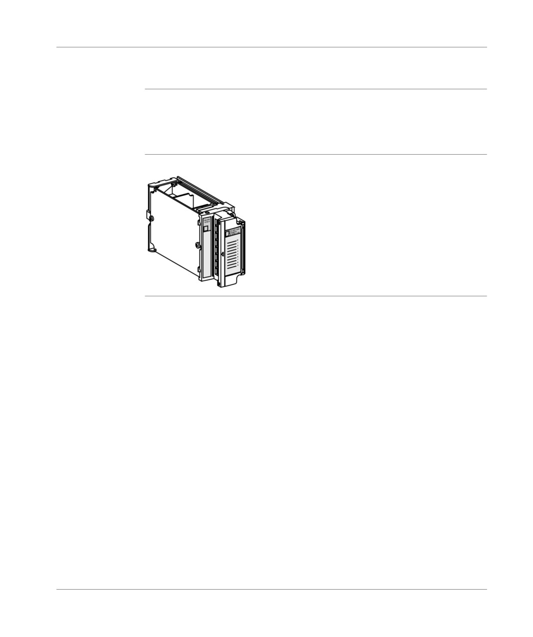
General
The TSX DPZ 10D2A safety module carries out a PREVENTA cabled safety
function in a half-size module and the complete diagnostics of the safety string.
It offers an emergency stop monitoring or position interrupting function, adapted to
the safety demands according to the EN 954-1, EN 418 and EN 60204-1 standards.
Illustration
safety module:
24
TSX DM 37 xxE
General introduction of the components of a PLC station
Local analog inputs/outputs
Introduction
The analog inputs/outputs from the TSX 37 range differ in their modularity, their
performance and signal ranges offered (high voltage level, thermoelectric couple,
heat probe, etc).
(For further details see TSX Micro implementation manual Volume 2).
Analog inputs/
TSX 37-22 PLCs offer 8 inputs and 0-10 V 8 bit-output, and a 10V voltage reference
outputs built in
output, which means that a large number of automatic cases can be answered
to TSX 37-22
economically.
PLCs
These inputs may be associated to the TSX ACZ 03 adjustment and adaptation
module, which allows:
manual adjustment of application values across 4 sliders,
conversion to 4-20 mA current from 0-10V signals,
adaptation of analog inputs to 24V discrete inputs (IEC type 1).
Illustration:
8 I 0-10V and 1 O 0-10V, 8 bits.
TSX DM 37 xxE
25
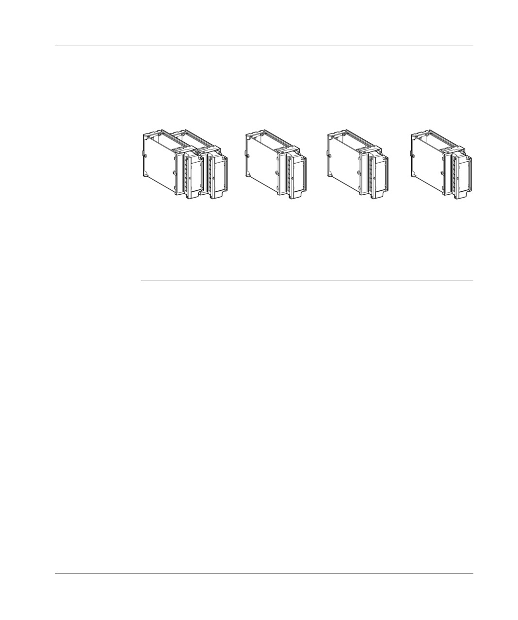
General introduction of the components of a PLC station
Analog input/
Analog input/output modules, which can be installed in all TSX 37-05/08/10/21/22
output module
PLCs offer a high level of performance. They differ in modularity (from 2 to 8
channels) and the input or output type (high voltage level, high current level,
thermoelectric couple-inputs, heat probe-inputs, etc.). The connection is always
made by a screw terminal block.
Illustration:
8I
4I
4O
2O
0-10 v +/- 10V
differentials
+/- 10V
+/- 10 V
or
multigrams
0-20 mA
0-20 mA 4-20 mA
(+/- 10V, 4-20 mA
16 bits+sign
4-20 mA
12 bits
Thermocouple, Pt
100,...)
11 bits + sign
16 bits
26
TSX DM 37 xxE
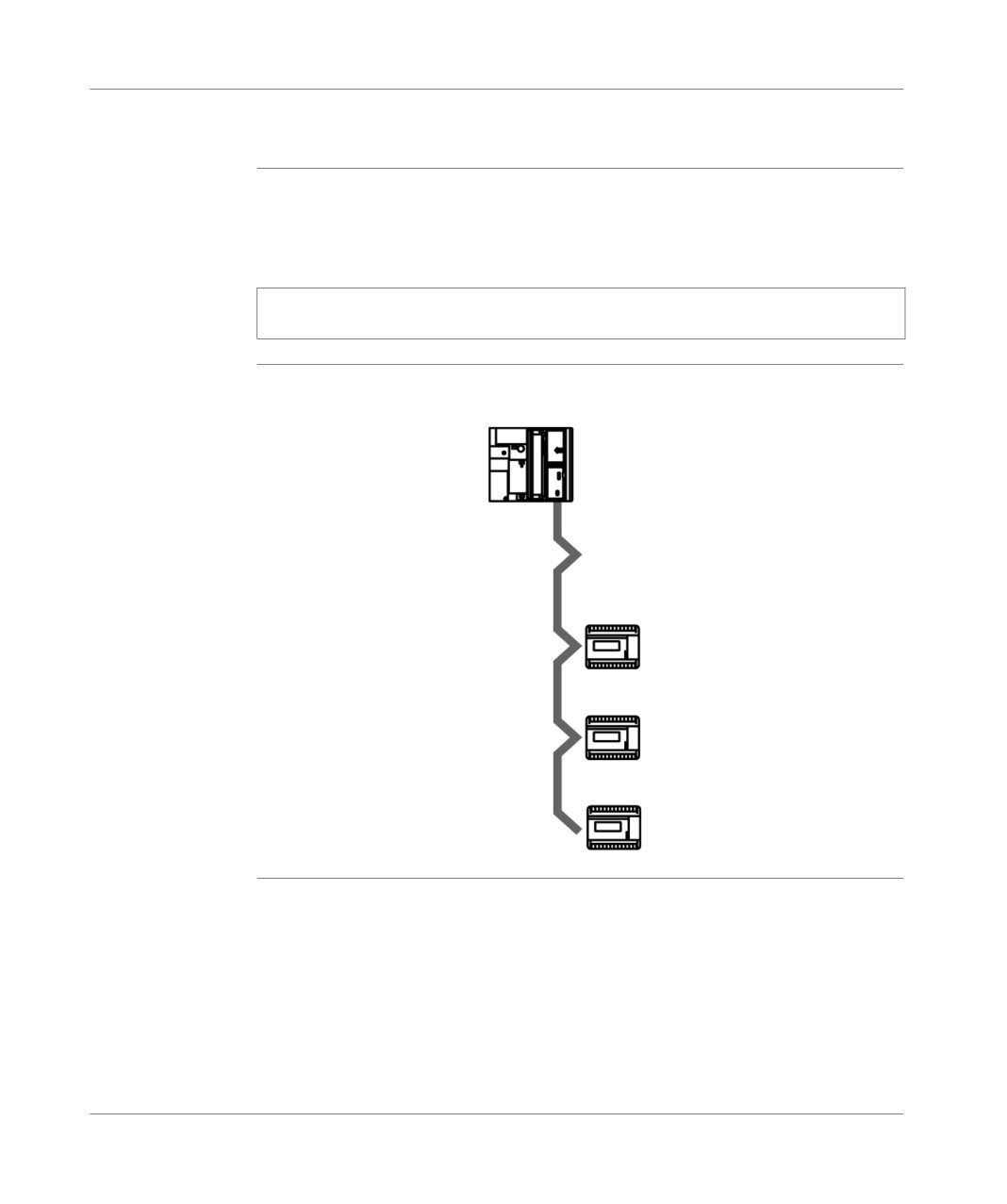
General introduction of the components of a PLC station
Remote analog inputs/outputs
General points
The TSX STZ 10 I/O offset module enables the remote use (up to a distance of
200m) of up to 3 TSX AMZ 4• analog input/output modules from the TSX 07 PLC
range (see Implementation manual TSX Micro Volume 2).
Note: Using an input/output offset module for PLCs excludes the use of an AS-i
master module.
Illustration
The schema below illustrates the connection between the TSX STZ 10 offset
module and the TSX AMZ 4 input/output module.
Bus length:
200 m max.
TSX AMN4.
TSX AMN4.
TSX AMN4.
TSX DM 37 xxE
27
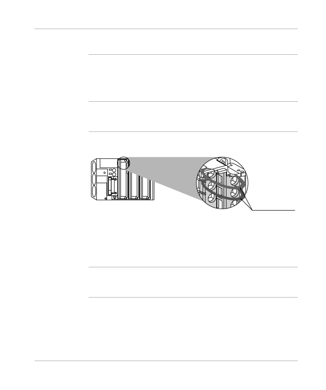
General introduction of the components of a PLC station
Counting channel
Introduction
TSX 37 PLCs offer 3 possibilities for counting:
via the first four discrete inputs of the first module,
by using the counting channels which are built in to TSX 37-22 PLCs,
via counting modules, which can be installed in the available positions (TSX CTZ
1A/2A, TSX CTZ 2AA).
Upcounting on
The first 4 inputs of the discrete module, located in the first slot of the PLC, make it
discrete inputs
possible to have 2 up/down counting channels at 500Hz.(See Counting built into
bases, p. 229.
Illustration
The illustration below shows the 4 inputs of the discrete module configurable in
counting channels.
2 counting channels
to 500 Hz:
up counter,
down counter,
up/down counter.
Integrated
Built-in counting in TSX 37-22 PLCs makes it possible to have 2 10KHz counting
upcounting
channels, as well as all the signals necessary for implementing these functions
(reset to zero, set to pre-selection, top-turn, etc.).
28
TSX DM 37 xxE
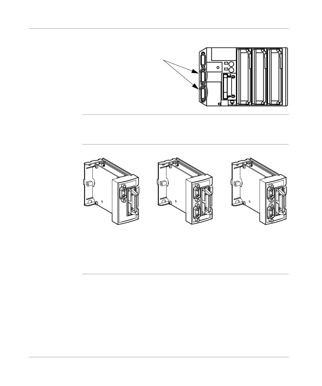
General introduction of the components of a PLC station
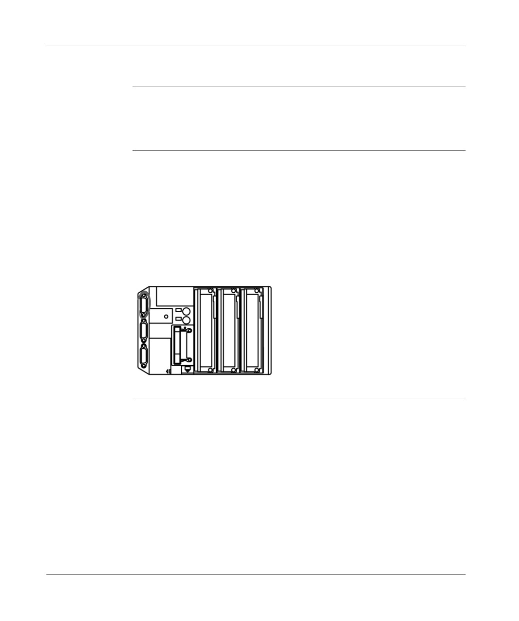
Illustration
The illustration below locates the 2 integrated counting channels.
2 x 10 KHz counting channels:
up counter,
down counter,
up/down counter (on the first channel).
Counting
The up and down counting modules differ in the number of channels offered, the
modules
40KHz or 500KHz counting frequency and the type and number of logical signals
complementary to up/down counting functions.
Illustration
The illustration below shows the different counting modules.
1 x 40 KHz
2 x 40 KHz
2 x 500 KHz
counting channel
counting channels
counting channels
up counter,
up counter,
up counter,
down counter,
down counter,
down counter,
up/down counter.
up/down counter.
up/down counter.
TSX DM 37 xxE
29
General introduction of the components of a PLC station
Forced PLC ventilation
Introduction
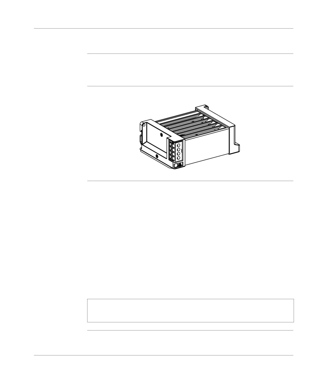
Depending on the PLC-type (TSX 37-05/08/10 or TSX 37-21/22 with or without mini
extension rack), one or two ventilation modules can be installed above each PLC to
assist the cooling of the different modules by forced convection.
Illustration
The illustration below shows the ventilation module TSX FAN •• •.
Usage
These ventilation blocks should be used in the following cases:
conditions
Ambient temperature between 25°C and 70°C: forced ventilation increases the
life span of the various TSX Micro PLC components (MTBF increased by 25%).
Ambient temperature between 60°C and 70°C: the ambient temperature is
limited to 60°C without ventilation, forced ventilation lowers the temperature
inside the modules by more than 10°C (and removes the hot points) which brings
the modules’ internal temperature down to the equivalent of the ambient
temperature of 60°C.
In these conditions, the product life span is increased by more than 50%.
Three types of ventilation module are offered:
Ventilation module with 110V AC supply,
ventilation module with 220V AC power supply,
ventilation module with 24V DC supply,
Note: Using forced ventilation makes it necessary to take fitting precautions when
analog modules of type TSX AEZ 414 are used in the PLC configuration (see (TSX
Micro Installation manual, Volume 2, cabling recommendations)).
30
TSX DM 37 xxE

General introduction to
communication
3
At a Glance
Aim of this
This chapter aims to provide a general description of communication with TSX Micro
Chapter
PLCs.
What's in this
This Chapter contains the following Maps:
Chapter?
Topic
Page
Communication
32
UNI-TELWAY link
33
Character mode link by terminal port
34
Modbus Connection
35
FIPWAY link
36
FIPIO link
37
Modem link
38
Modbus Plus Link
39
TSX DM 37 xxE
31
General introduction to communication
Communication
General
TSX 37 PLCs offer a series of economic multidrop links via the terminal port of all
the PLCs and an additional permanent connection for the operator dialog on TSX
37-21/22 PLCs.
These connections enable the connection of (one single protocol at a time):
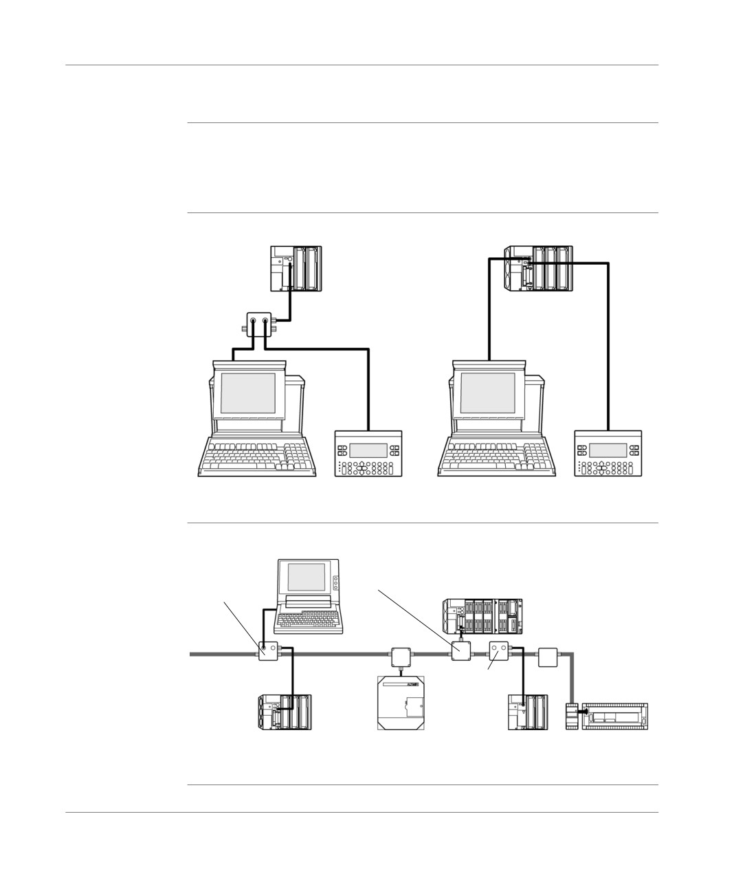
a programming terminal and/or an operator dialog device (UNITELWAY master
mode),
the PLC to an UNI-TELWAY multidrop link (UNI-TELWAY master or slave mode),
the PLC to the Modbus bus,
a printer or a terminal in character mode,
a m odem.
A TSX P ACC 01 enables the PLC to be connected to a UNI-TELWAY link, when
the distance between the devices is greater than 10 meters. If desired, it makes it
possible to duplicate the terminal port in order to simultaneously connect a console
and an operator dialog device on a TSX 37 05/08/10 PLC.
TSX 37-21 and TSX 37-22 PLCs are also fitted with a slot which makes it possible
to receive a communication module in PCMCIA format (full-duplex or half-duplex,
UNI-TELWAY, JBUS/MODBUS, FIPWAY, FIPIO Agent, Modbus+, modem
asynchronous series of links).
32
TSX DM 37 xxE
General introduction to communication
UNI-TELWAY link
General
Communicating via UNI-TELWAY allows the exchange of data between all the
devices which are connected on the bus. The UNI-TELWAY standard is a UNI-TE
protocol which creates a hierarchical structure (one master and several slaves).
The master device is the bus manager.
UNI-TELWAY
Illustration:
master link by
TSX 37-05/08/10
terminal port
TSX 37-21/22
Insulating device
TSX P ACC01
UNI-TELWAY
Illustration:
slave link by
Insulating
Branching device
terminal port and
device
TSX SCA 50
master by
TSXP ACC01
PCMCIA module
TSX 37-21
Master
UNI-TELWAY
Insulating
device
TSXP
ACC01
TSX 37-21 Slave
ALTIVAR
TSX 17
TSX 37-10
Slave
TSX DM 37 xxE
33
General introduction to communication
Character mode link by terminal port
General
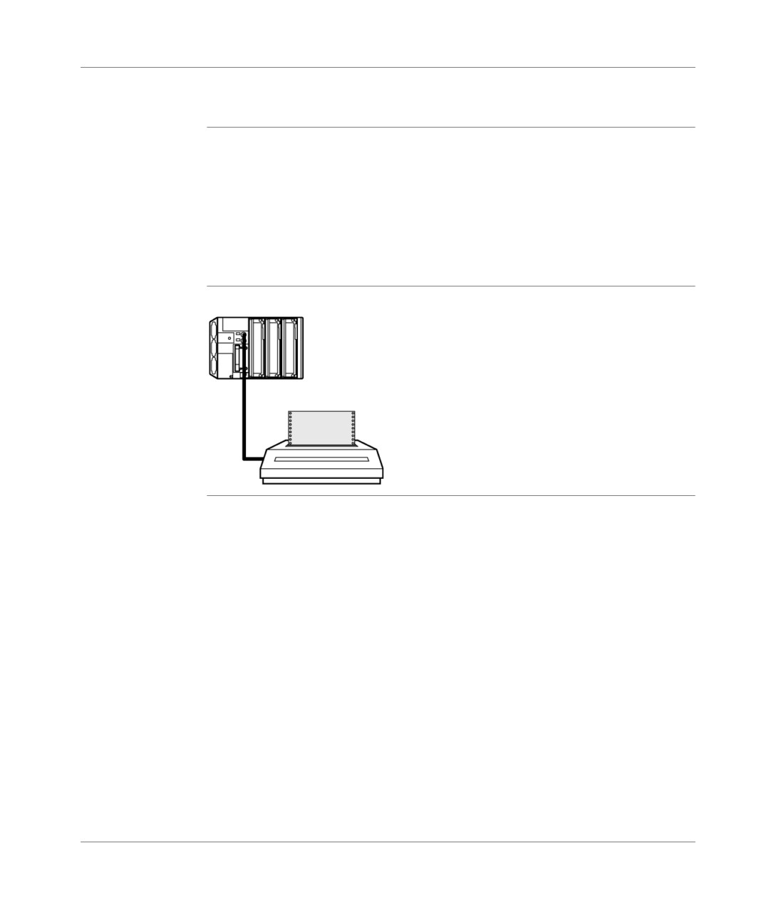
Communication via character mode enables dialog and communication functions to
be carried out between the PLCs and their environment.
common peripherals: printers, keyboard-screen, workshop terminal,
specialized peripherals: bar code readers,
link to a checking or production management calculator,
data transmission between heterogeneous devices (numerical commands,
variable speed controllers, etc),
link to an external modem.
Illustration
character mode link to a printer:
34
TSX DM 37 xxE
General introduction to communication
Modbus Connection
General points
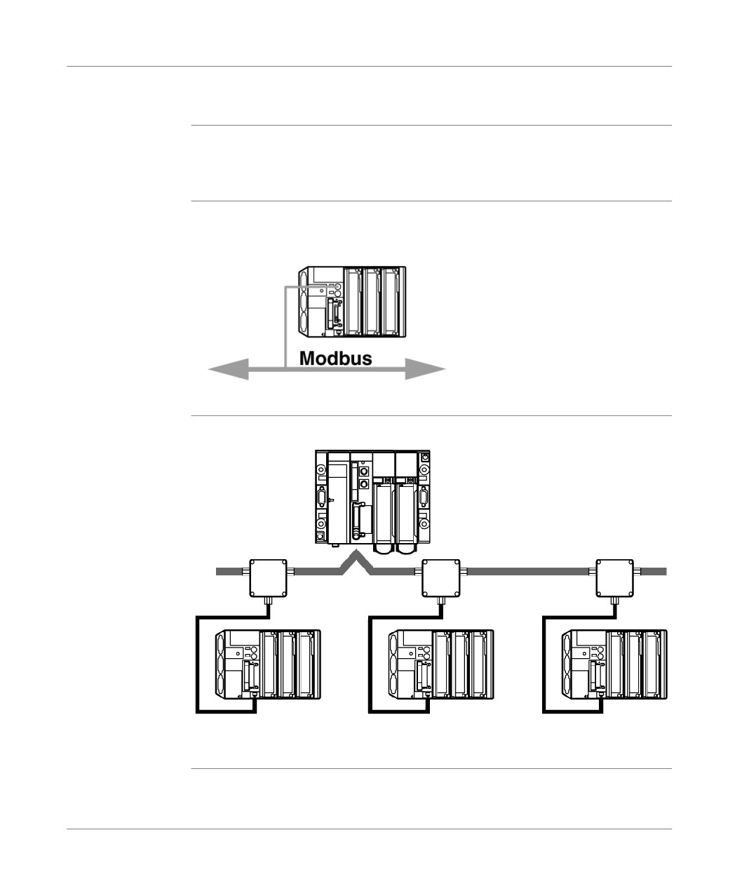
Communicating via Modbus allows data exchange between the master and all the
slave devices which are connected on the bus. The Modbus protocol is a protocol
which creates a hierarchical structure (one master and several slaves).
Illustration
connection to Modbus bus via terminal port:
TSX 37-05/08/10/21/22
JBUS/MODBUS
Illustration:
link via
TSX 57
communication
Master
module
TSX SCA 50
branching
device
JBUS/MODBUS
TSX 37-21
TSX 37-21
TSX 37-21
slave
slave
slave
TSX DM 37 xxE
35
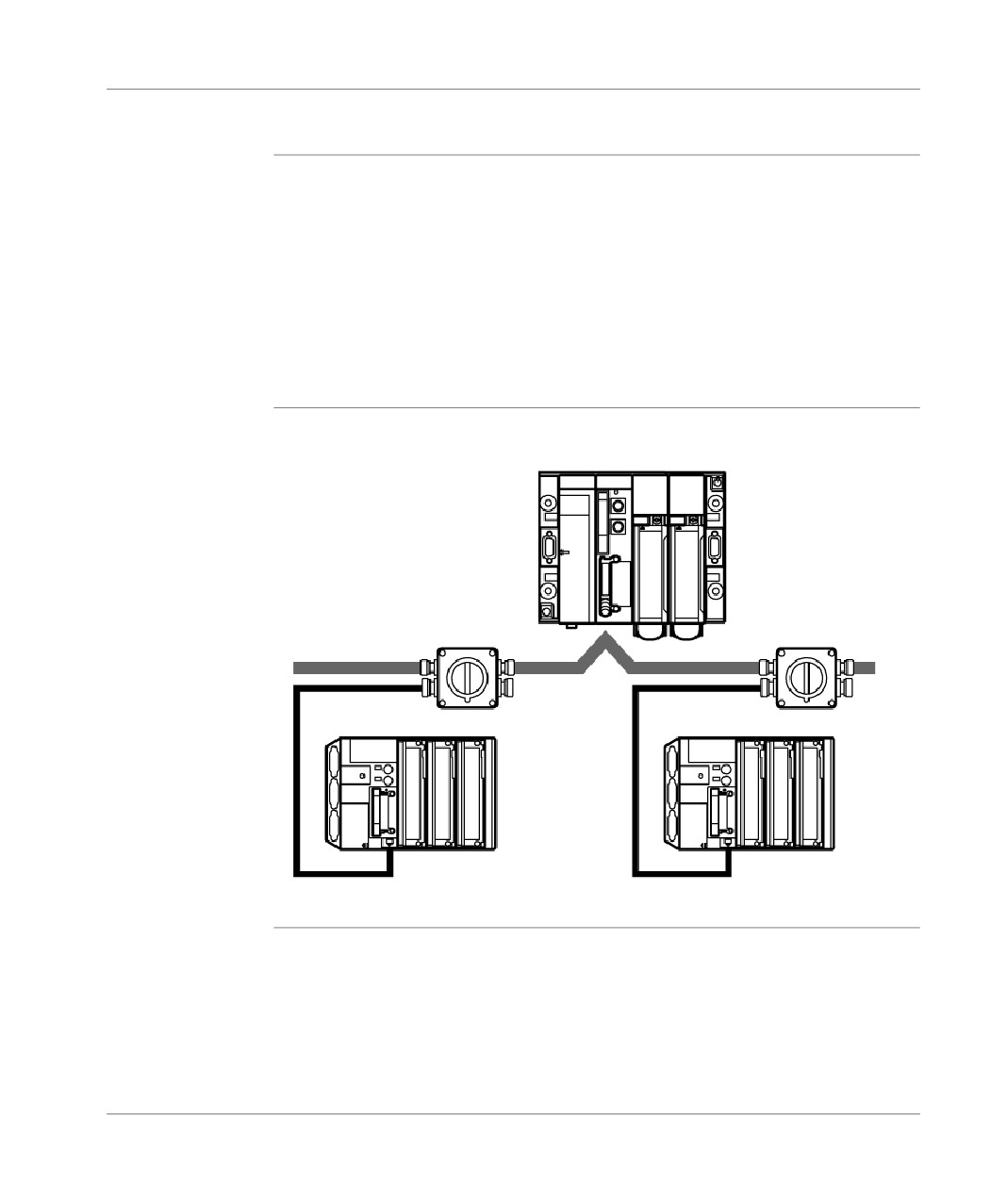
General introduction to communication
FIPWAY link
General points
To decentralize peripheral devices, intelligence and ultra-remote services,
Schneider Automation offers the FIPWAY industrial local network.
The FIPWAY network conforms entirely to the FIP standard with access by a bus
arbitrator.
A FIPWAY communication channel comprises three elementary functions:
The inter-station message handling function which guarantees the routing of
messages,
the telegram sending/receiving function,
the common words (%NW) or shared table production/consumption function.
Illustration
connection to the FIPWAY network via communication module:
TSX 57
FIPWAY
TSXFPACC4
TSX 37-22
TSX 37-21
36
TSX DM 37 xxE
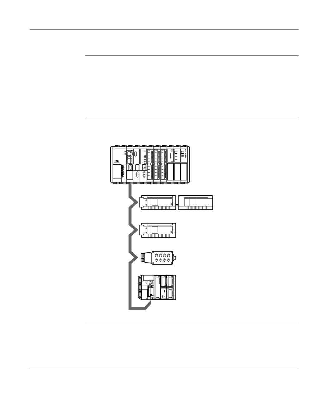
General introduction to communication
FIPIO link
General
Communicating via FIPIO is part of the WORLDFIP global offer from Schneider
Automation.
FIPIO is a field bus, which allows the decentralization of the inputs/outputs of a PLC
station and its industrial peripheral devices nearest to the operational part.
The FIPIO protocol depends on the producer/consumer exchanges (example:
common words) and the bus is managed by a bus arbitrator.
Illustration
FIPIO link by communication module:
TSX series 7
TBX
TBX
FIPIO
TBX
TSX 37-22
TSX DM 37 xxE
37
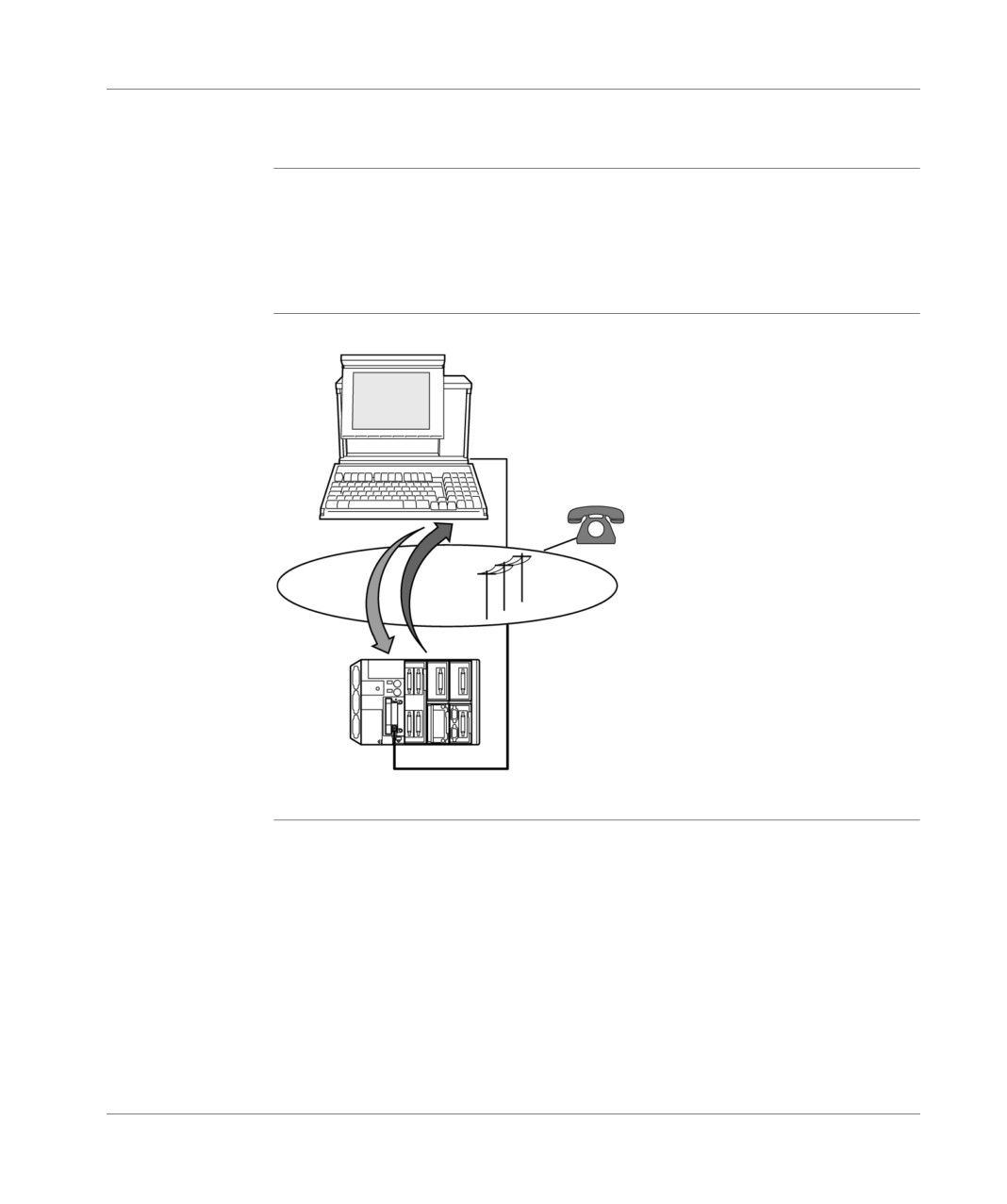
General introduction to communication
Modem link
General
A large number of applications are affected by modem communications.
Communicating via the TSX MDM 10 modem makes it possible to access stations,
which have been offset by the switched public telephone network in order to carry
out checks, diagnostics, or remote controls.
Illustration
connecting to the telephone network with a PCMCIA card modem:
TSX 37-21/22
38
TSX DM 37 xxE
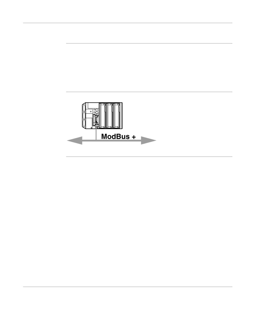
General introduction to communication
Modbus Plus Link
General
Communicating by Modbus Plus allows the exchange of data between all the
devices connected on the network.
The Modbus Plus protocol is based on the principle of a Logical Token passing bus.
Each station on the same network is identified by an address between 1 and 64 and
has access to the network after receiving a token. Duplicated addresses are not
valid.
Illustration
Illustration:
TSX 37-21/22
TSX DM 37 xxE
39
General introduction to communication
40
TSX DM 37 xxE
Addressing system
4
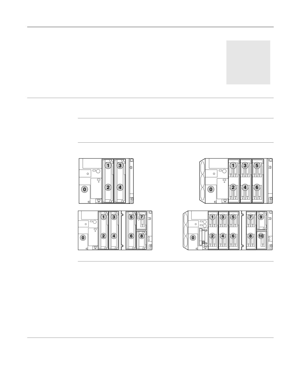
Channel address settings
General points
The channel address settings are geographic; i.e. they depend on the physical
position of the module in the PLC or extension.
Illustration
The illustration below shows some configuration examples
TSX DM 37 xxE
41
Addressing system
Rules
Given that the basic module size is half-size, full-size modules are addressed as two
superimposed half-size modules.
The term Position represents either a half size module, or the upper or lower part
of a full-size module.
Discrete input/output syntax is as follows:
%
I or Q
Position
Channel
Symbol
%I: input
1 to 4 (37 05/10)
Connection
i
%Q: output
1 to 6 (37 08/21/22
1 to 8 (37 10 + RKZ02
1 to 10 (37 21/22 + RKZ02
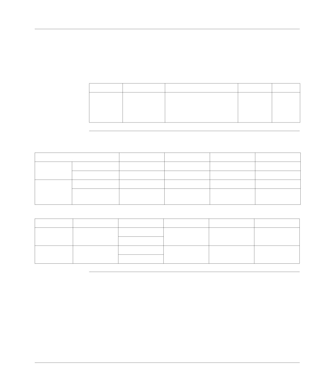
Channel address The table below provides the channel address settings by full-size format module
setting
type.
64 I/O
32 I
32 O
28 I/O
Channel
Odd position
0 to 31
0 to 15
0 to 15
0 to 15
number i
Even position
0 to 31
0 to 15
0 to 15
0 to 11
Channel
Odd position
%Ix.0 to %Ix.31
%Ix.0 to %Ix.15
%Qx.0 to %Qx.15
%Ix.0 to %Ix.15
Address
Even position
%Q(x+1).0 to
%I(x+1).0 to
%Q(x+1).0 to
%Q(x+1).0 to
%Q(x+1).31
%I(x+1).15
%Q(x+1).15
%Q(x+1).11
The table below provides the channel address settings by half-size module type.
16 I/O
12 I
8O
4O
Channel
Odd or even
E: 0 to 7
0 to 11
0 to 7
0 to 3
number i
position
S: 8 to 15
Channel
Odd or even
%Ix.0 to %Ix.7
%Ix.0 to %Ix.11
%Qx.0 to %Qx.7
%Qx.0 to %Qx.3
Address
position
%Qx.8 to %Qx.15
42
TSX DM 37 xxE
//////////////////////////////////////////