TSX Micro PLCs TSX 3705/3708/3710/3720. Implementation Manual (Volume 1) - page 3
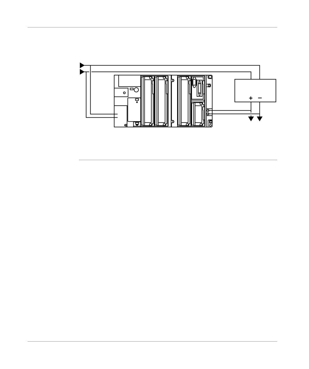
Mini extention rack
Illustration
supply and extension:
Alternating network
Supply
24 VDC (1)
towards sensors connected
to discrete I/O cards
mounted in the extension
(1) TSX SUP• Supply Process, see (TSX Micro Installation manual, Volume 2).
TSX DM 37 xxF
83
Mini extention rack
84
TSX DM37 xxF

TSX 37 PLC performance
12
Performances
Acquisition time
data table:
for the discrete
Number of inputs
0
16
32
48
60
72
84
96
inputs (in the
base or in the
Acquisition time for
77
176
270
356
448
539
623
708
inputs without errors
extension)
(microseconds)
Acquisition time for an
11
8.44
7.42
7.47
7.49
7.42
7.36
input (microseconds)
Update time for
data table:
the discrete
Number of outputs
0
12
24
36
44
52
60
68
outputs (in the
Update time for the
42
189
314
454
573
691
825
1031
base or in the
outputs
extension)
(microseconds)
Update time for one
15.75
13.08
12.61
13.02
13.29
13.75
15.16
output (microseconds)
TSX DM 37 xxE
85
Performance
Event
This is the time between the occurrence of an event (for example rising edge on an
processing time:
EVT input of the module 1, presetting on a counting channel of the TSX 37-22 base
SRT
or of a TSX CTZ module, etc.) and the assignment of a discrete output.
SRT = 1.5 ms (SRT = Software Response Time)
Note: Inputs 0 to 3 of module 1 should be configured with a minimum filtering value,
so that they can be used in EVT inputs.
Cycle time for an application.
To calculate the overall cycle time of a discrete application, the following must be
added:
the system overhead corresponding to the type of PLC,
the program execution time for the number of kilo instructions,
the acquisition time for the discrete inputs,
the update time for the discrete outputs.
For details of all these times, refer to (Reference manual PL7, volume 3,
performances).
Note: To find out the true current duration of an application, with the help of the
debug processor screen, you must subtract from the displayed value a value of 2
ms, corresponding to the time taken by the PLC to process information requested
by the console or the network module.
The maximum duration indicated in this screen can have a high value, if a PCMCIA
format communication module is present in the PLC.
86
TSX DM 37 xxE

Commissioning standards and
conditions
13
At a Glance
Aim of this
This chapter is about the TSX Micro PLCs commissioning standards and conditions
Chapter
What's in this
This Chapter contains the following Maps:
Chapter?
Topic
Page
Standards and certifications
88
Operating conditions and environmental recommendations
89
Protection treatment for TSX 37 Micro PLCs
90
TSX DM 37 xxE
87
Commissioning standards and conditions
Standards and certifications
General points
The TSX 37 PLCs were designed to comply with the main national and international
standards for industrial process control electronic equipment:
programmable PLCs: specific requirements: functional characteristics, immunity,
strength, safety, etc.
IEC 61131-2, CSA 22.2 No.142, UL 508,
merchant navy requirements of the major international bodies:
ABS, BV, DNV, GL, LROS, RINA, RRS, CCS, etc.
compliance with European Directives:
Low Voltage: 73/23/EEC amendment 93/68/EEC
Electromagnetic Compatibility: 89/336/EEC amendments 92/31/EEC and 93/68/
EEC,
electric qualities and self-extinguishability of insulating materials:
UL 746C, UL 94, etc.
hazardous locations Cl1 Div2 CSA 22.2 No.213:
"THIS EQUIPMENT IS SUITABLE FOR USE IN CLASS I, DIVISION 2,
GROUPS A, B, C AND D ON NON-HAZARDOUS LOCATIONS ONLY".
WARNING: "EXPLOSION HAZARD - DO NOT DISCONNECT WHILE CIRCUIT
IS LIVE UNLESS AREA IS KNOWN TO BE NON-HAZARDOUS"
88
TSX DM 37 xxE

Commissioning standards and conditions
Operating conditions and environmental recommendations
Description
Temperature, humidity, altitude:
Ambient operating temperature
0°C to +60°C (IEC 1131-2 = +5°C to +55°C)
Relative humidity
10% to 95% (without condensation)
Altitude
0 to 2000 meters
Power supply voltages:
Voltages
nominal
24 VDC
100..240 VAC
limit
19..30 VAC (1)
90..264 VAC
Frequencies
nominal
50/60 Hz
limit
47/63 Hz
(1) 34 VDC for one hour per 24 hours, for a battery device with charger.
TSX DM 37 xxE
89

Commissioning standards and conditions
Protection treatment for TSX 37 Micro PLCs
General points
TSX 37 PLCs meet all "TC" treatment requirements (1).
For installations in industrial production workshops or in an atmosphere
corresponding to "TH" treatment (2), TSX 37 PLCs must be embedded in IP54
minimal protection envelopes as recommended in standards IEC 60664 and NF C
20 040.
The TSX 37 PLCs themselves display an IP20 protection index (3).
They can therefore be installed without an envelope in restricted access locations
not exceeding pollution degree 2 (control rooms containing no dust-producing
machines or activities).
(1) "TC" treatment: treatment for all climates.
(2) "TH" treatment: treatment for warm and humid atmospheres.
(3) In the event that position is not occupied by a module, a TSX RKA 01 protection
cover needs to be mounted.
Human and
Human and material safety standards (1):
material safety
EC
Test Designation
Standards
Levels
yes
Dielectric strength and Insulation
IEC61131-2
24V supply
1500V RMS
resistance *
UL 508
100-220V supply
2000V RMS
CSA 22-2 No.142
< 48V Discrete I/Os
500V RMS
IEC60950
> 48V Discrete I/Os
2000V RMS
R> 10MΩ
yes
Ground continuity
IEC61131-2
< 0.1Ω / 30Α / 2µιν
UL 508
CSA 22-2 No.142
yes
Leakage current
CSA 22-2 No.142
Fixed devices < 3.5mA
IEC60950
yes
Protection via envelopes
IEC61131-2
IP20 with RKA01 covers
CSA 22-2 No.142
IEC60950
no
Impact Resistance
CSA 22-2 No.142
Drop / 1.3m / 500g Sphere
IEC60950
(1) the devices must be installed and wired according to the directions in the TSX
DG KBLF manual.
90
TSX DM 37 xxE

Commissioning standards and conditions
Resistance of the
Standards concerning the resistance of the devices to power supply L.F turbulence
devices to power
(1):
supply L.F.
turbulence
EC
Test Designation
Standards
Levels
yes
Voltage and frequency Variation
EN 50082-1
Un +/- 15% / Fn +/- 5%
30 min x 2
Un +/-20% / Fn +/-10%
15s x 2
yes
DC voltage variation
EN 50082-1
0.85Un - 1.2Un
30 + 30 min
+ 5% ripple maximum
yes
Harmonic 3
IEC 61131-2
10% Un
0° / 5min - 180° / 5min
yes
Momentary Interruptions
IEC 61131-2
AC
10ms
DC
1ms
yes
Voltage peaks and troughs
IEC 61131-2
Un-0-Un ; Un/60s
3 cycles separated by 10s
Un-0-Un ; Un/5s
3 cycles separated by 1 to 5s
Un-0.9Ud ; Un/60s
3 cycles separated by 1 to 5s
(1) the devices must be installed and wired according to the directions in the TSX
DG KBLF manual.
TSX DM 37 xxE
91

Commissioning standards and conditions
Resistance to
Standards concerning L.F turbulence (1):
H.F. turbulence
EC
Test Designation
Standards
Levels
yes
Absorbed oscillatory wave
IEC 61131-2
AC/DC
1kV MS
IEC 61000-4-12
Discrete I/O ≥ 24ς
1kV MS
yes
Fast transients (bursts)
EN 50082-1
AC/DC supply
2kV MF / MC
IEC 61000-4-4
Discrete I/O > 48ς
2kV MC
other ports
1kV MC
no
Hybrid shockwave
IEC 61000-4-5
AC/DC supply
2kV MF / 1kV MS
Discrete AC I/Os
2kV MF / 1kV MS
Discrete DC I/Os
2kV MF / 0.5kV MS
Shielded Cable
1kV MC
yes
Electrostatic Discharge
IEC 61131-2
6kV contact
IEC 61000-4-2
8kV air
yes
Electromagnetic Field
EN 50082-2
10V/m from 27MHz to 1GHz
IEC 61000-4-3
Sinusoidal Modulation Amplitude 80% / 1kHz
yes
Conduit Turbulence
EN 50082-2
3V from 0.15MHz to 80MHz
IEC 61000-4-6
Sinusoidal Modulation Amplitude 80% / 1kHz
(1) the devices must be installed and wired according to the directions in the TSX
DG KBLF manual.
Electromagnetic Standards concerning electromagnetic emissions (1):
emissions
EC
Test Designation
Standards
Levels
yes
Conduction Limits
EN55022/55011
Class A
EN50081-2
150kHz -500kHz
near-peak 79dB V
average 66dB V
500kHz -30MHz
near-peak 73dB V
average 60dB V
yes
Radiation limits
EN55022/55011
Class A
d = 10m
EN50081-2
30MHz - 230MHz
near-peak 30dB V
230MHz - 1GHz
near-peak 37dB V
(1) the devices must be installed and wired according to the directions in the TSX
DG KBLF manual.
92
TSX DM 37 xxE

Commissioning standards and conditions
Resistance to
Standards concerning electromagnetic emissions (1):
climatic variation
EC
Test Designation
Standards
Levels
no
Dry heat
IEC 60068-2-2 Bd
60°C / 16h (E.O)
40°C / 16h (E.F)
no
Cold
IEC 60068-2-1 Ad
5°C / 16h
no
Continuous humid heat
IEC 60068-2-30 Ca
60°C / 93% Hr / 96h (E.O)
40°C / 93% Hr / 96h (E.F)
no
Cyclical humid heat
IEC 60068-2-30 Db
(55°C E.O / 40°C E.F) - 25°C / 93-95% Hr
2 cycles: 12 o' clock - 12h o' clock
no
Cyclical temperature variations
IEC 60068-2-14 Nb
0°C - 60°C / 5 cycles: 6 o'clock-6 o'clock
(E.O.)
0°C - 40°C / 5 cycles: 6 o'clock-6 o'clock (E.F)
no
Temperature Rise
IEC 61131-2
Ambient temperature: 60°C
UL 508
(70°C with ventilation TSXFANNxxP
CSA 22-2 No.142
(1) the devices must be installed and wired according to the directions in the TSX
DG KBLF manual.
Resistance to
Standards concerning electromagnetic emissions (1):
mechanical
constraints
EC
Test Designation
Standards
Levels
no
Sinusoidal vibrations
IEC 60068-2-6 Fc
3 Hz - 100Hz / 1mm amplitude / 0.7g
Endurance: fr / 90min / axis
3 Hz -150Hz / 1mm amplitude / 2g
Endurance: 10 cycles (1 octave / min)
no
Half-sinus shocks
IEC 60068-2-27 Ea
15g x 11ms)
3 impacts / direction /
axis
(1) the devices must be installed and wired according to the directions in the TSX
DG KBLF manual.
TSX DM 37 xxE
93
Commissioning standards and conditions
Resistance to
Standards concerning resistance to climatic variation (1):
climatic variation
EC
Test Designation
Standards
Levels
no
Dry heat whilst inoperative
IEC 60068-2-2 Bb
70°C / 96h
no
Cold whilst inoperative
IEC 60068-2-1 Ab
-25°C / 96h
no
Humid heat whilst inoperative
IEC 60068-2-30 dB
55°C ; 25°C / 93%Hr ; 95 %Hr
2 cycles: 12 o' clock - 12h o' clock
no
Thermal shocks whilst inoperative
IEC 60068-2-14 Na
-25°C ; 25°C
2 cycles: 3 o'clock - 3 o'clock
(1) the devices must be installed and wired according to the directions in the TSX
DG KBLF manual.
Resistance to
Standards concerning resistance to mechanical constraints (1):
mechanical
constraints
EC
Test Designation
Standards
Levels
no
Flat free drop
IEC 60068-2-32 Ed
10cm / 2 drops
no
Free drop from controlled position
IEC 60068-2-31 Ec
30° or 10cm / 2 drops
no
Random free drop (conditioned
IEC 60068-2-32
0.5m / 5 drops
material)
Option 1
(1) the devices must be installed and wired according to the directions in the TSX
DG KBLF manual.
Abbreviations
EC: tests required by EC directives,
used
Un: nominal voltage,
Fn: nominal frequency,
Ud: detection level under power,
MS: serial mode,
MC: common mode,
MF: wired mode,
E.O: open device,
E.F: closed device,
Hr: relative humidity,
f.r: resonance frequency.
94
TSX DM 37 xxE
TSX 37 PLC: Mounting
III
At a Glance
Aim of this Part
This part describes the installation and connection of the TSX 37 PLCs.
What's in this
This Part contains the following Chapters:
part?
Chapter
Chaptername
Page
14
TSX 37 PLC: installation
97
15
TSX 37 PLC: connection
117
16
Ventilation module
135
TSX DM 37 xxE
95
TSX 37 processor: Mounting
96
TSX DM 37 xxE

TSX 37 PLC: installation
14
At a Glance
Aim of this
This chapter describes the installation of the TSX 37
PLCs, their container and the
Chapter
different modules.
What's in this
This Chapter contains the following Maps:
Chapter?
Topic
Page
Rules of installation
98
Dimensions
100
PLC mounting/fixing
101
Mounting the base onto a DIN profile (or rail)
102
Mounting the PLC onto a board or panel
103
Procedure for assembling the extension with the base
104
Inserting a module
106
Removing a module
108
Inserting/changing the battery
110
Mounting/removing the memory card
112
Changing the battery on the PCMCIA card
114
Screw tightening torque
116
TSX DM 37 xxE
97
Installation
Rules of installation
PLC
Certain rules must be respected for installing containers and inserting modules
arrangement
during the mounting of the TSX 37 PLCs:
The PLCs should be air-cooled by natural convection. To facilitate their
ventilation, they should be installed vertically with the ventilation louvers on the
top. Only the horizontal position is therefore authorized.
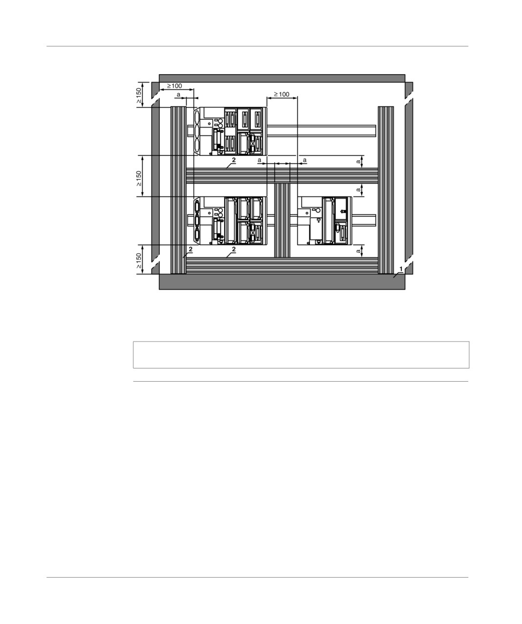
If several PLCs are installed in the same rack, it is recommended that the
following provisions be respected:
leave a space of at least 150 mm between two overlapped PLCs, to allow a
passage for the wiring ducts and to facilitate air circulation,
it is advised to install heat generating devices (transformers, supply modules,
power switches, etc) above the PLCs,
leave a space of at least 100mm at each side of a PLC (with or without
extension) to allow a passage for the wiring and to facilitate air circulation,
if the internal RAM memory is backed up by a battery (optional), it will be
necessary to provide sufficient space (>= 50 mm) between the PLC and the
duct, in order to allow the hatch to be opened and access to the battery.
98
TSX DM 37 xxE
Installation
Illustration
Principle diagram:
(1) >= 50 mm
1 Installation or casing.
2 Trough or cable tray.
Note: In the case of the use of ventilation devices, see Rules for installation of the
racks with ventilation modules, p. 143
TSX DM 37 xxE
99
Installation
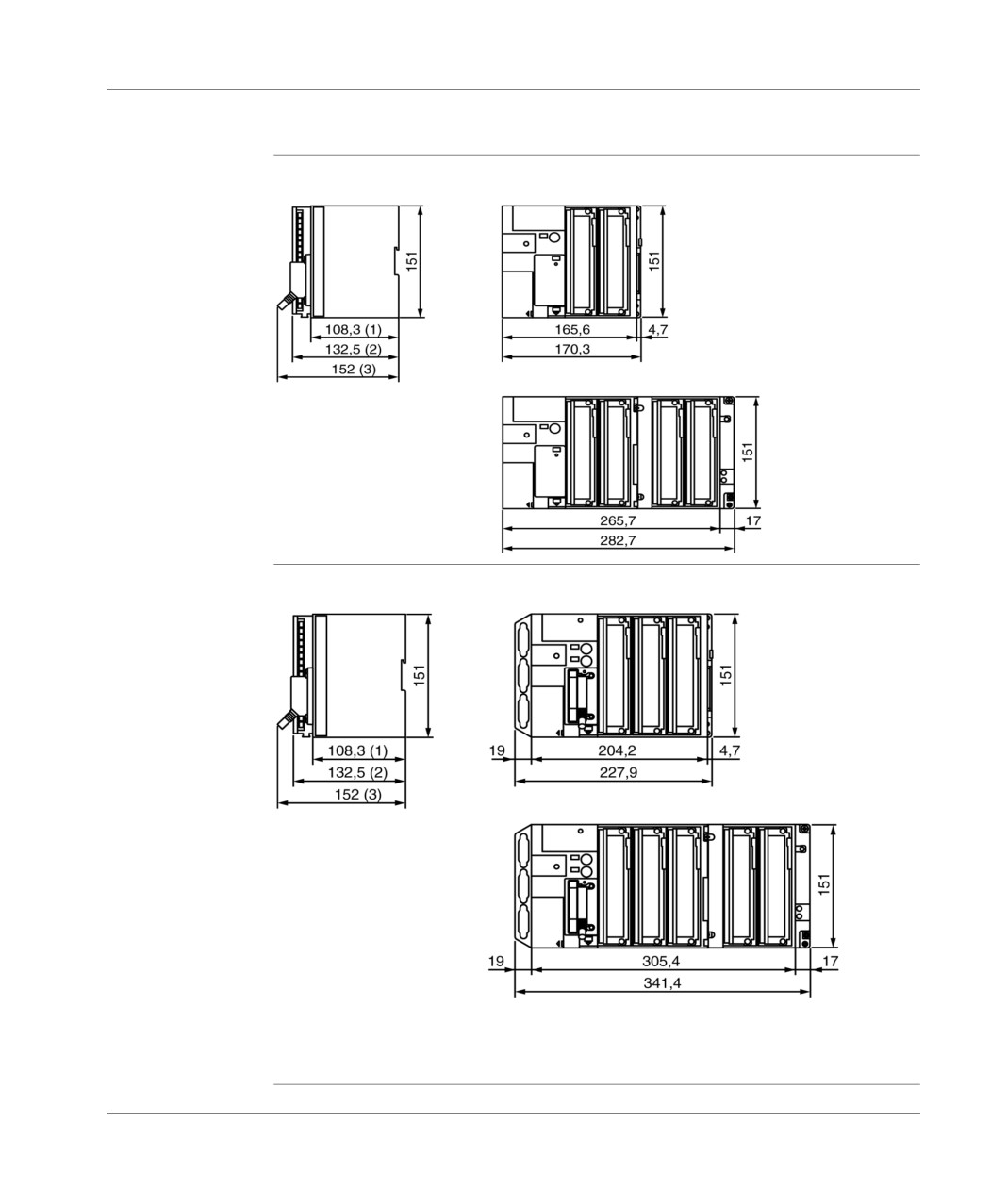
Dimensions
TSX 37-05 / TSX
37-10 PLCs
TSX 37-05 and TSX 37-10
without mini extension rack
TSX RKZ02
TSX 37-10
(1) PLC empty
with mini rack
(2) With screw terminal
extension
block.
TSX RKZ02
(3) With HE10 or SubD
connectors
TSX 37-08/ TSX
37-21/TSX 37-22
TSX 37-08 and
PLCs
TSX 37-21/22
without TSX RKZ02
mini-extension rack
TSX 37-21/22 with
TSX RKZ02 mini-extension
rack
(1) PLC empty.
(2) With screw terminal block.
(3) With HE10 or SubD connector.
100
TSX DM 37 xxE
Installation
PLC mounting/fixing
General
The TSX 37 PLCs, with or without mini extension rack can be mounted on a DIN
profile, a Telequick board or on a panel:
the process of fixing onto a DIN profile requires no accessories,
the process of fixing onto a Telequick board or on a panel is performed by 4
screws with a diameter of M4 for the base and 2 screws with a diameter of M4 for
the mini extension rack, these 6 screws are not supplied. If mounting is difficult,
from a mechanical point of view, it is preferable to fix the PLC onto a board or
panel.
The installation rules (See Rules of installation, p. 98) are to be respected, whatever
the type of mounting.
TSX DM 37 xxE
101
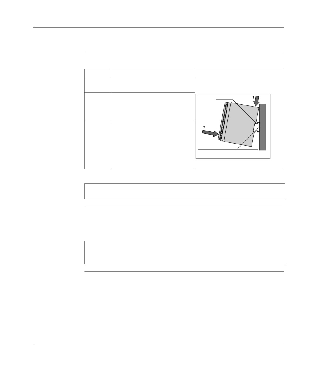
Installation
Mounting the base onto a DIN profile (or rail)
Procedure to be Carry out the following steps:
followed
Step
Description
Illustration
1
Position the PLC on the DIN profile as
indicated by the diagram.
2
Push down on the back part of the
ressort
PLC (1), to compress the springs,
then tip it backwards against the
profile (2).
3
Release the PLC in order to lock it.
profilé chapeau larg.35 mm :AM1-DE200
Note: This type of fitting does not comply with normal operating conditions in terms
of resistance to vibrations (acceleration: 2g).
Dismounting the
To dismount the PLC, carry out the steps for the mounting process in reverse, i.e.:
PLC from the DIN
push down on the back part of the PLC (1), to compress the springs, then tip it up
profile (rail)
towards the front to disengage it from the DIN profile (2).
Note: In order to guarantee the good working order of PLCs in a strict
electromagnetic environment, it is necessary to mount the modules on metal
supports which are correctly grounded.
102
TSX DM 37 xxE
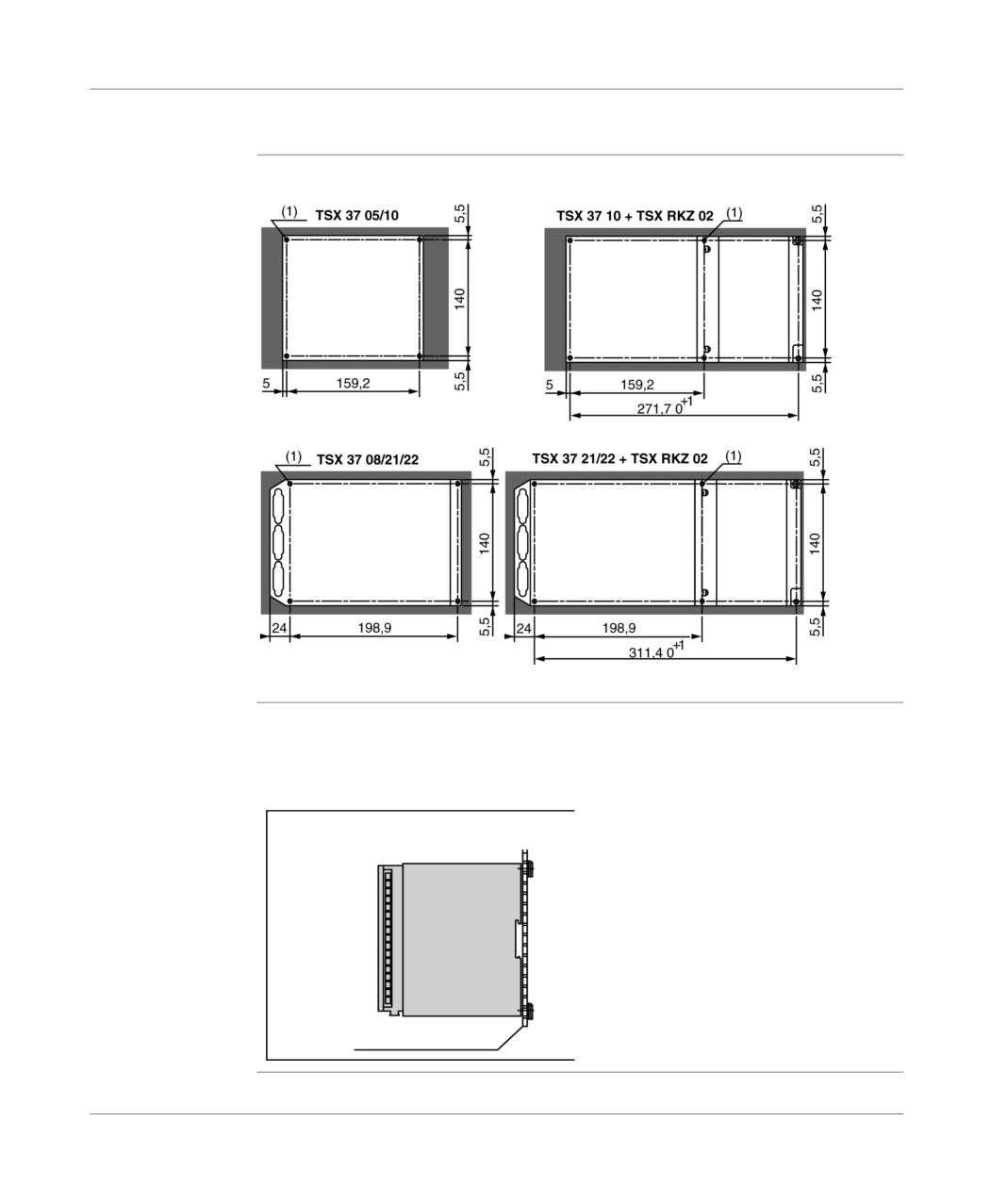
Installation
Mounting the PLC onto a board or panel
Mounting
Illustration (side in millimeters) :
distance
(1) The diameter of the fixing holes must be sufficient to take M4 screws.
Procedure for
Fix the base with 4 screws with a diameter of 4, mounted in the fixing holes located
mounting the
in the elbows of the PLC (4 screws with M4x16AF1-VA416 captive washers and 4
PLC onto a
M4 AF1-EA4 clip nuts).
Telequick board
Illustration:
AM1-PA board
TSX DM 37 xxE
103
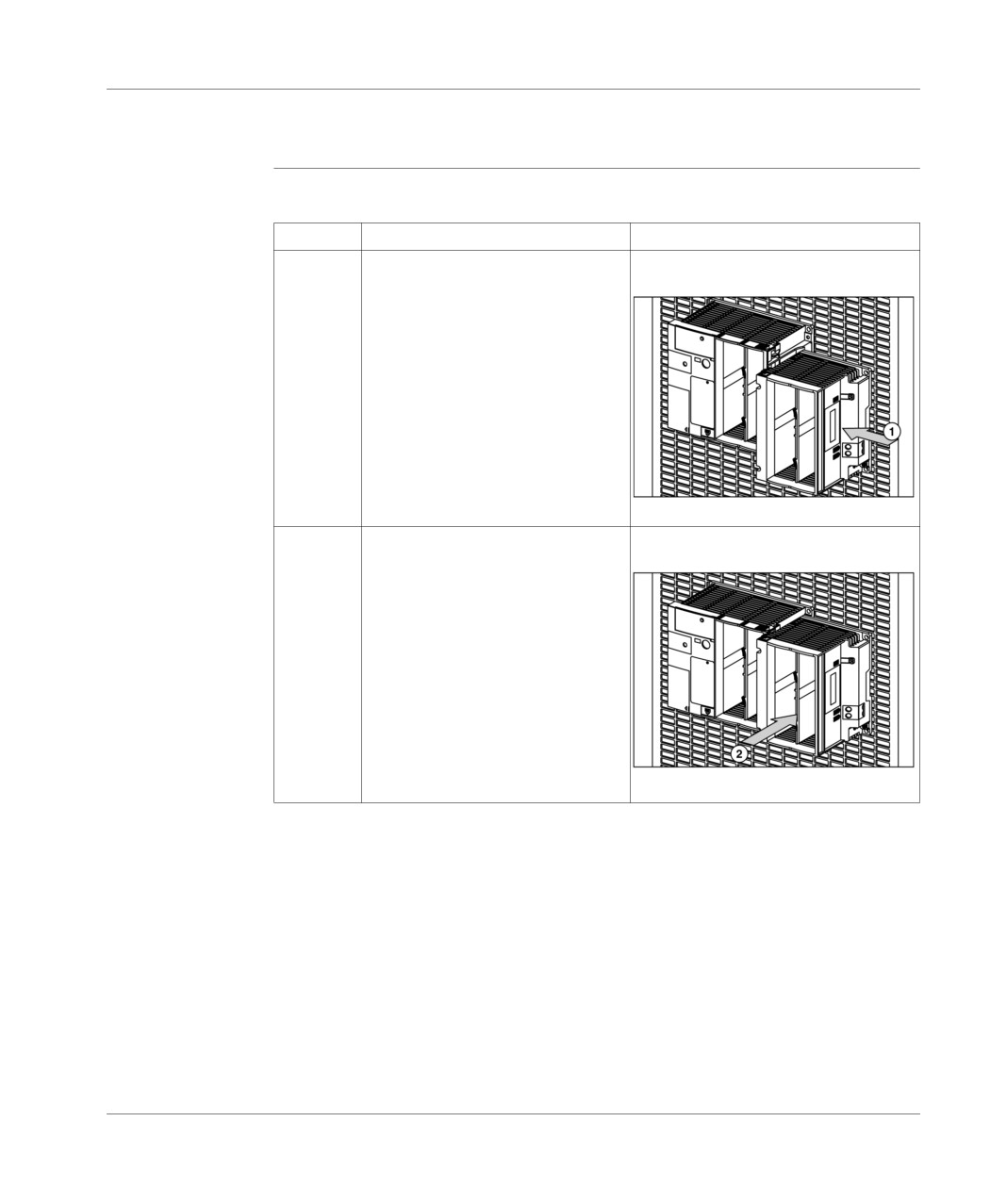
Installation
Procedure for assembling the extension with the base
Procedure
Carry out the following steps:
Step
Action
Illustration
1
Remove the access cover to the
connection connector of the mini
extension rack.
2
Pin the mini extension rack against
the PLC base, with an offset to the
front of approx. 1 cm, then slide it to
the back, in order to check the
mechanical coupling and the
connection of the 2 elements.
104
TSX DM 37 xxE
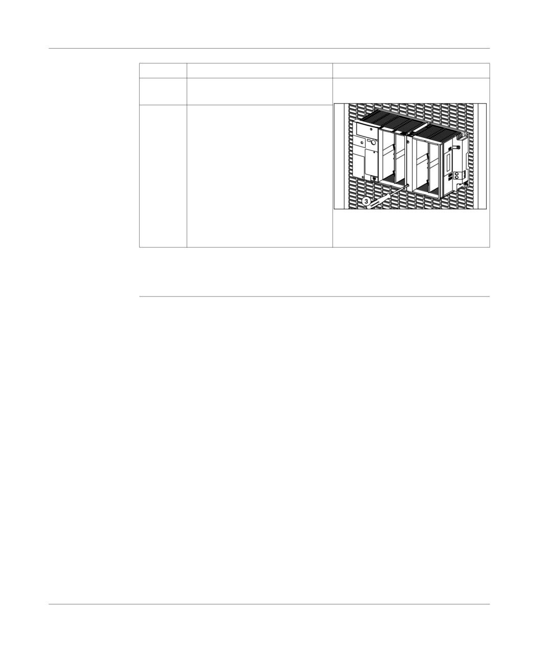
Installation
Step
Action
Illustration
3
Screw on the 2 mini extension rack
captive screws, to fix to the base.
4
If the PLC is mounted onto a board or
panel and to improve vibration
resistance, it is possible to fix the mini
extension rack onto the board, in
addition to operation (3). In order to
do this, use 2 screws with a diameter
of 4, mounted in the oblong fixing
holes of the mini extension rack (2
screws with M4x16 AF1-VA416
captive washers and 2 M4 AF1-EA4
clip nuts).
If the PLC is mounted on the DIN profile, the mini extension rack is not fixed to it, but
is fixed to the base (with additional support from a lateral spring).
TSX DM 37 xxE
105
Installation
Inserting a module
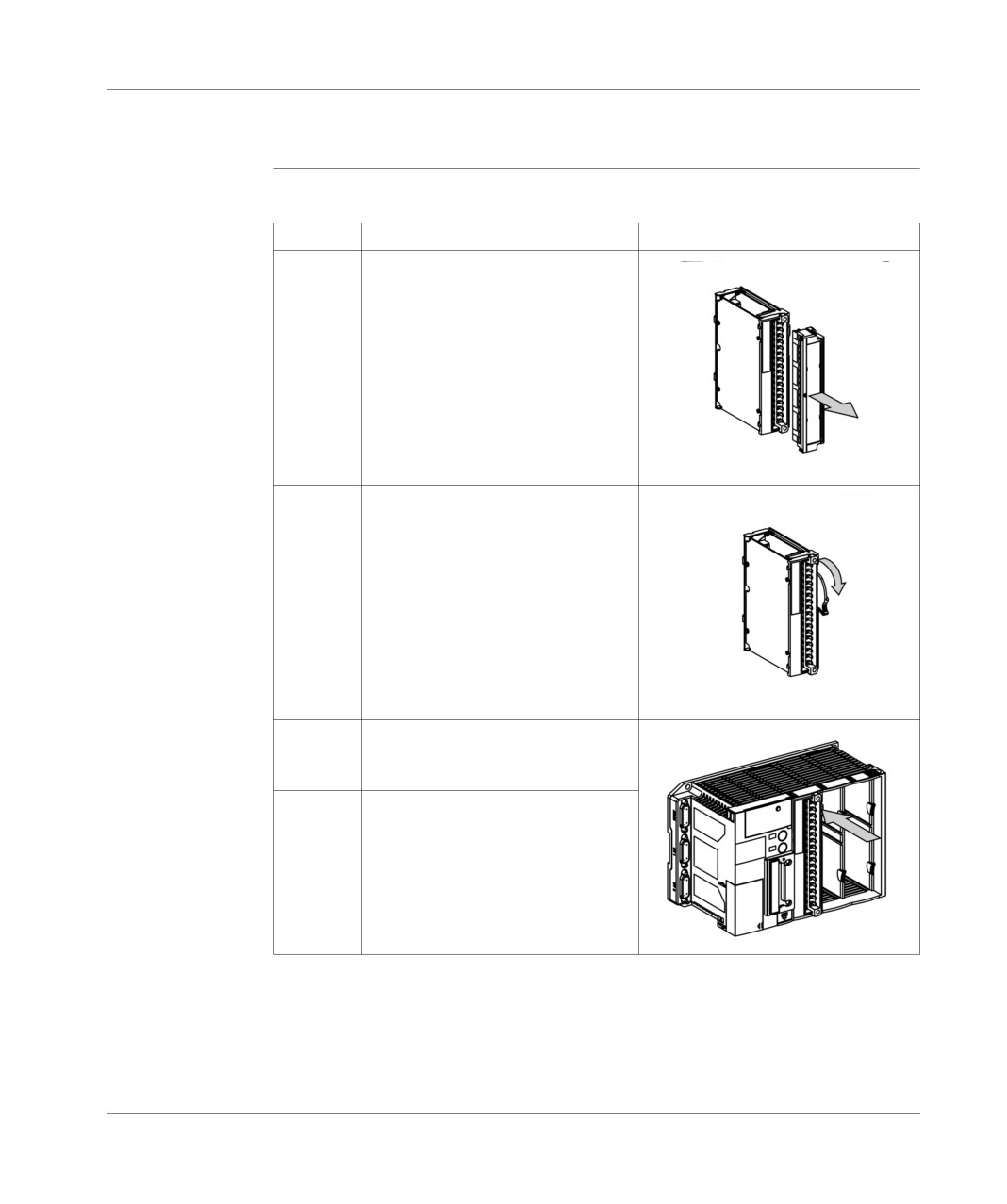
Procedure to be Carry out the following steps:
followed
Step
Action
Illustration
1
If the module is equipped with a screw
terminal block, remove it by
successively unscrewing the 2 fixing
screws. This operation progressively
disconnects the terminal block. You
are advised not to totally unscrew one
screw and then the other, but alternate
between the two.
2
Set the latch to the "unlocked" position
by switching it to the bottom of the
module.
3
Slide the module into its slot; this is
helped by runners. Then push the front
of the module in order to connect it.
4
Switch the latch up, which locks the
module.
106
TSX DM 37 xxE
Installation
Step
Action
Illustration
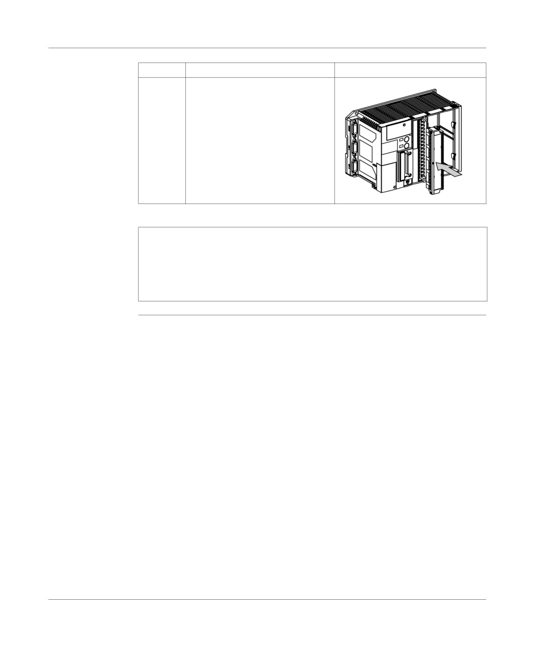
5
If the module is equipped with a screw
terminal block, insert it, alternatively
screw the 2 screws, which
progressively connects the terminal
block to the module.
Note: In order to maximize individual safety in relation to equipment supplied with
100120 V or 200240 V, the life span of the equipment and to avoid disrupting input/
output exchanges; mounting a module or terminal block should be performed
under the following conditions:
PLC switched off for the module,
sensor and pre-actuator voltage cut for the terminal block.
TSX DM 37 xxE
107
Installation
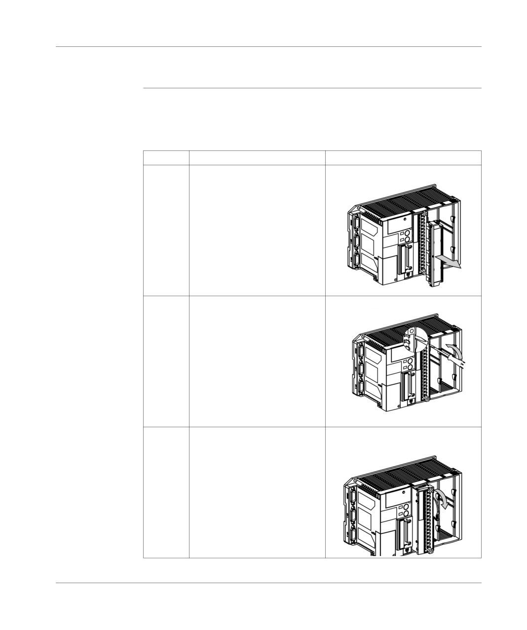
Removing a module
Procedure to be Removing a module is performed following the same sequence as for inserting a
followed
module in a rack.
Carry out the following steps:
Step
Action
Illustration
1
If a module has a terminal block,
remove it.
2
Switch the latch down to disconnect
the module. To do this, insert the tip
of a flat screwdriver into the groove
provided and lever towards the
bottom to start unlocking the
module.
3
Finish levering the latch by hand,
which disconnects the module.
108
TSX DM 37 xxE
Installation
Step
Action
Illustration
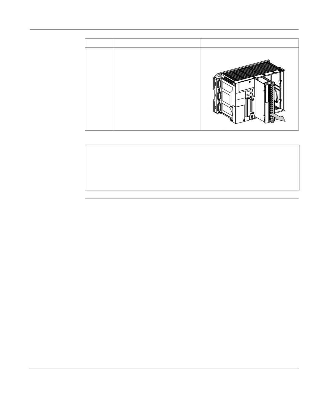
4
Slide the module out of its slot by
pulling it forwards.
Switch the latch up and if necessary
fix the terminal block back onto the
module.
Note: In order to maximize individual safety in relation to equipment supplied with
100120 V or 200240 V, the life span of the equipment and to avoid disrupting input/
output exchanges; dismounting a module or terminal block should be performed
under the following conditions:
PLC switched off for the module,
sensor and pre-actuator voltage cut for the terminal block.
TSX DM 37 xxE
109
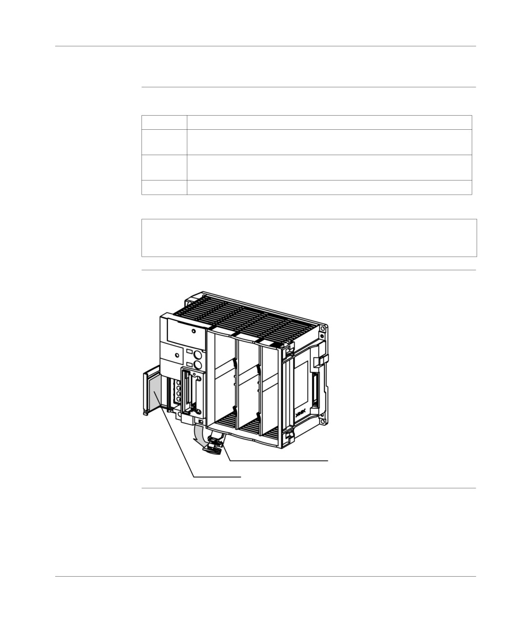
Installation
Inserting/changing the battery
Installing the
Carry out the following steps:
battery
Steps
Action
1
Unlock the battery access door by pressing on the front panel. This opens the
door downwards.
2
Place the battery in its slot, taking care to respect polarities as marked on the
module.
3
Push the door back up to close and lock.
Note: This operation can be carried out when the PLC is on or off. If the power
supply is cut off when the battery is being changed, the RAM is backed up for a
maximum of 30 minutes.
Illustration
battery slot:
battery access door
label
110
TSX DM 37 xxE

Installation
Changing the
The battery (TSX PLP 01), which backs up the internal RAM should be changed
battery
every 2 years or when the BAT light lights up (voltage supplied by a < 2.5 V battery).
To do this, use the same sequence as for inserting a battery:
Step
Action
1
Push the battery access door to open it downwards.
2
Remove the defective battery from its slot.
3
Put in the new battery, observing the polarities.
4
Push the door back up to close and lock.
Important
To ensure that the battery is changed every 2 years, you are advised to note the date
of the next change on the label provided for this purpose and located on the inside
of the access door of the supply terminal blocks.
Illustration:
Note: When the battery supply voltage becomes less than 2 V, the internal RAM is
no longer backed up (from 30 minutes onwards), when the PLC is switched off.
TSX DM 37 xxE
111
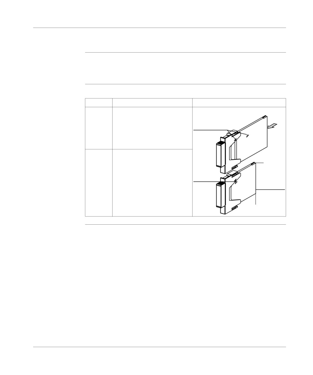
Installation
Mounting/removing the memory card
Introduction
The memory card must be equipped with a handle to be inserted into the slot
(normally factory-fitted). If this is not the case, mount the handle on the card by
following the procedure described below.
Mounting the
Carry out the following steps:
handle
Step
Action
Illustration
1
Position the end of the memory card
unequipped with a connector at the
entry to the handle. During this
repères
operation, align the markings (in the
form of a triangle) on the handle and
on the card label.
2
Slide the memory card into the
détrompeur
à 1 rebord
handle until it stops. The card is
now firmly attached to the handle.
repères
connecteur
détrompeur à 2
rebords
112
TSX DM 37 xxE
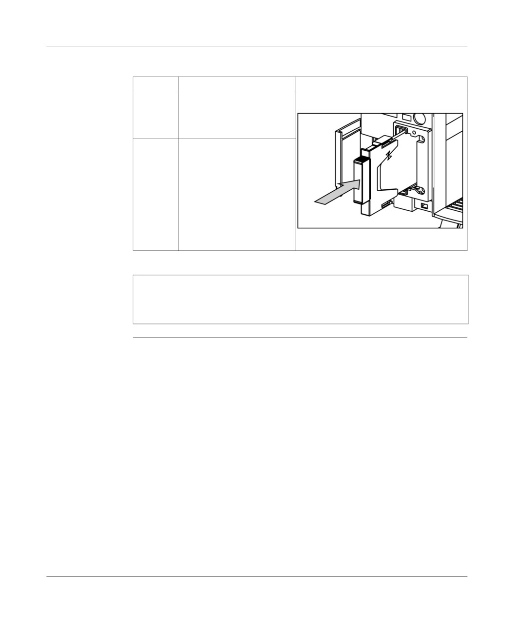
Installation
Mounting the
To insert the PCMCIA card into the PLC, carry out the following steps:
memory card in
Step
Action
Illustration
the PLC
1
Remove the protective cover
by unlocking it, then pulling it
towards the front of the PLC
(use a screwdriver).
2
Place the PCMCIA card fitted
with its handle into the opened
slot. Slide the assembly in until
the card can go no further, then
press on the handle to connect
the card.
Note: When inserting the PCMCIA card into its slot, check that the hardware
locating devices are correctly positioned:
1 edge on top,
2 edges down (or write protection down)
TSX DM 37 xxE
113
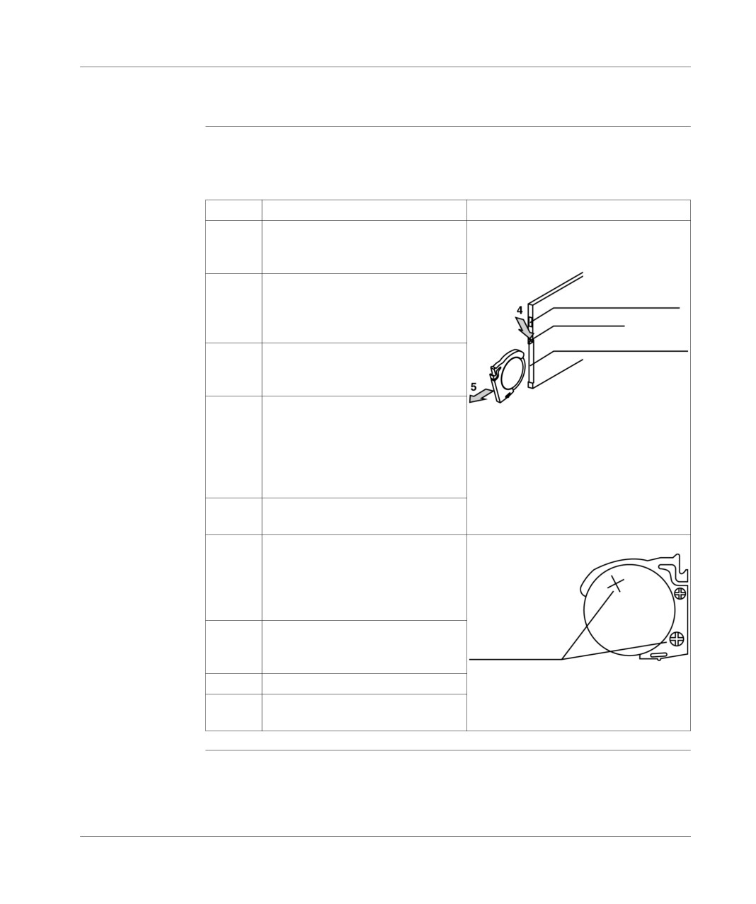
Installation
Changing the battery on the PCMCIA card
Procedure to be
Some PMCIA cards are equipped with a battery, with the product reference TSX
followed
BATM01, which must be changed.
To do this, perform the following steps:
Step
Action
Illustration
1
Remove the card from its slot by
pulling the handle forwards out of the
PLC.
2
Separate the PCMCIA card from its
Protection en écriture
handle by pulling the two components
(card and handle) in opposite
Verrou
directions.
Emplacement de la pile
3
Hold the PCMCIA card so you can
access the battery slot. This is at the
end of the card without the connector.
4
Unlock the battery holder, which is at
the end of the card without the
connector. To do this, depress the
latch down from the card (opposite
direction to the write protect
microswitch) by pulling it backwards.
5
Remove the battery and holder unit
from its slot.
6
Swap the defective battery for an
identical 3V battery. Polarities must
be observed by placing the + signs on
the holder and the battery on the
same side.
7
Place the battery and holder unit back
in its slot, then lock it. To do this, carry
repère
out the removal procedure in reverse.
8
Fix the PCMCIA card into its handle.
9
Put the card with its handle back into
the PLC.
114
TSX DM 37 xxE
Installation
Battery life
data table:
PCMCIA card stored in normal conditions (-20°C to 70°C)
12 months
PCMCIA card fitted in an operating PLC (0°C to 60°C)
36 months
Note: When in operation, the ERR LED flashes if there is a fault with the PCMCIA
card battery.
TSX DM 37 xxE
115
Installation
Screw tightening torque
General
data table:
Technological elements
Maximum tightening torque
Fixing screws of the PLCs, modules and terminal blocks
0.8 N.m
Ground connection screws
Discrete module terminal block screws
0.8 N.m
Supply terminal block screws
SUB D connector screws
Different cable and lead connector screws
TSX DMZ 16 DTK/etc. module casing terminal block
0.5 N.m
screws
116
TSX DM 37 xxE

TSX 37 PLC: connection
15
At a Glance
Aim of this
This Chapter deals with the connection of TSX 37 PLCs.
Chapter
What's in this
This Chapter contains the following Maps:
Chapter?
Topic
Page
Ground connection of the PLC
118
Grounding the modules
119
Supply connections
120
Connection rules
121
Connecting PLCs supplied with alternating current
122
Connecting several PLCs supplied by TBX SUP 10 or TSX SUP supplies
125
Connecting PLCs supplied with direct current
126
Connecting PLC(s) supplied by a continuous floating network (not grounded)
129
Specific provisions for a continuous floating network
131
Sensor and pre actuator supply control
132
TSX DM 37 xxE
117
Connection
Ground connection of the PLC
General
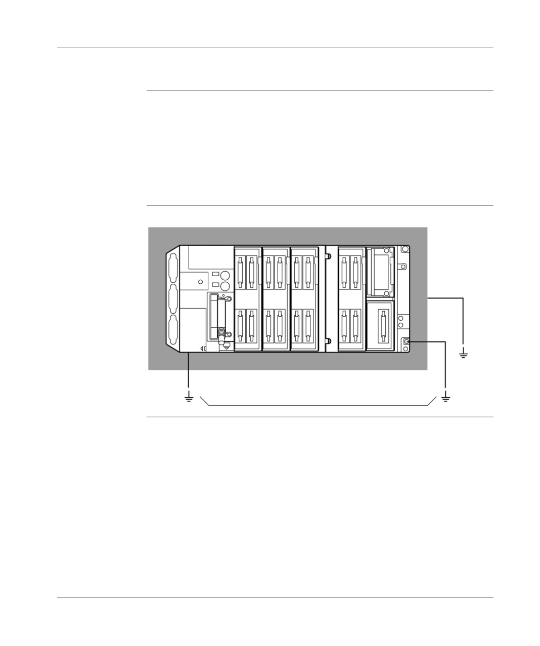
Grounding the TSX 37 bases and mini extension rack is provided by the rear
section, which is metallic. This guarantees efficient working order for PLCs in
environment norms, on condition however that they be fixed on a correctly grounded
metal support. The base and extension should be mounted on the same support or
supports, which are correctly coupled together.
To ensure personal safety, it is always necessary to ground the base ground
connection terminals and the mini extension rack.
For this, use a 2,5 mm2 (minimum) green/yellow wire of the shortest length possible.
Illustration
Ground connections:
support connected
to the ground
green and yellow wire
connected to the ground
118
TSX DM 37 xxE
Connection
Grounding the modules
General
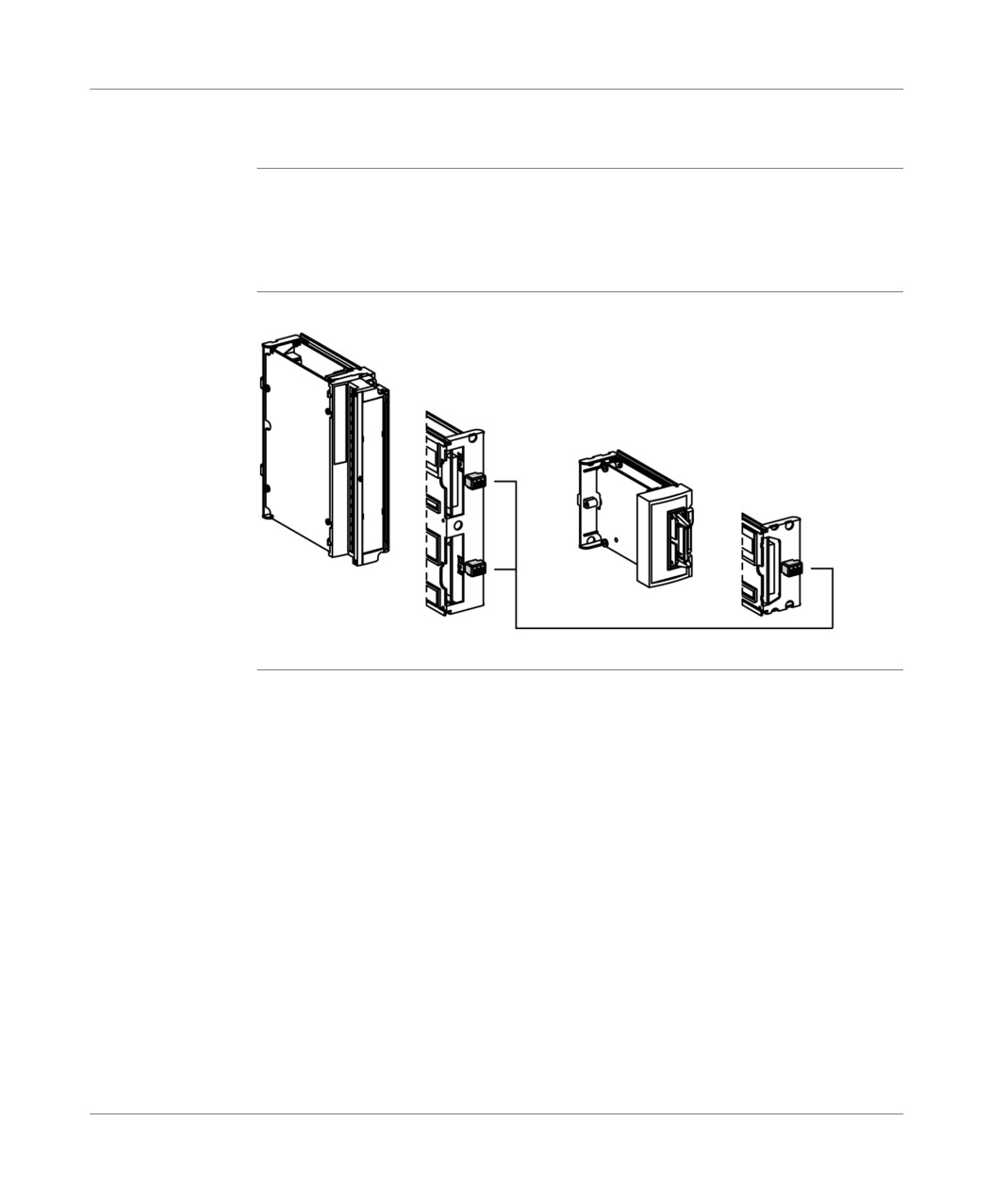
Grounding the modules is performed with a contact on the back (2 contacts for the
modules in standard format), which connects to a metallic finger forming a part of
the PLC base or mini extension rack when inserted into a module. This connection
ensures grounding.
Illustration
Ground connection:
Ground contact
TSX DM 37 xxE
119
Connection
Supply connections
Introduction
The TSX 37 range offers two possibilities for the supply of PLCs:
alternating current,
and direct current.
The PLC is
the base delivers the 24 VDC (24 VR) voltage necessary to supply the coils of its
supplied with
integrated relay modules,
alternating
however, the mini extension rack must be supplied with 24 VDC in the following
current
cases:
analog modules are positioned in the extension,
relay modules are positioned in the extension, The 24 VDC supply tolerance
must be +/- 10% max. If this voltage disappears or there is a reduction of more
than 10%, good working order of the relay modules is no longer ensured. No
error indication is given to the application program. If detection of this error is
desired, you are advised, for example, to use a dividing bridge inline with an
analog input of the base configuration.
Note: When the PLC is supplied with alternating current, it is strictly forbidden to
use the 24 V sensor voltage, provided by the base, to supply the mini extension
rack with 24 VDC (24 VR).
The PLC is
The base delivers the 24 VDC (24 VR) voltage necessary to supply the coils of
supplied with
the relay/analog modules that are integrated in the base and/or the mini
direct current (24
extension rack.
VDC not
The TSX 37 PLCs and modules can continuously function in a voltage range
insulated)
between 19 and 30 VDC (and up to 34 VDC for 1 hour for a battery operated
device with charger).
However, if relay modules are fitted to the PLC (base or extension), the 24 VDC
supply should have a maximum tolerance of +/- 10%.
A TSX SUP supply can be used to provide the 24 VDC voltage (refer to wiring
diagrams on the following pages).
120
TSX DM 37 xxE
Connection
Connection rules
General
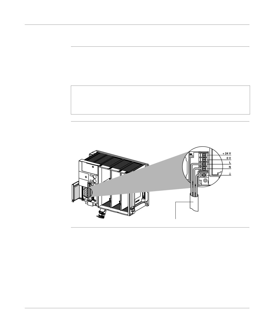
The TSX 37 PLC supply terminal block is protected by a door, which allows access
to the wiring terminals. Wire output passes vertically to the bottom. Wiring can be
maintained in position by a cable tightening clip.
Note: Plan for a device, which protects and cuts the supply upstream of the PLC.
When the PLC is supplied by a direct network, the length of the supply cable must
be limited to 30 m if the wires have a cross section of 2.5 mm2 or 20 m if the wires
have a cross section of 1.5 mm2, to prevent a loss of line.
Illustration
Principle diagram:
cable-tightening pass
TSX DM 37 xxE
121
Connection
Connecting PLCs supplied with alternating current
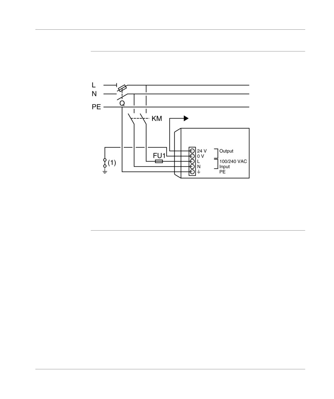
Connecting a
Illustration:
single PLC
Alternating network 100-240 V
Sensor supply
base+extension (2)
Q: general isolator,
KM: line contactor or circuit breaker,
Fu1: 1 A fuse with time delay.
(1) : isolation strip for finding grounding faults,
(2) : do not exceed 400 mA.
122
TSX DM 37 xxE