TSX Micro PLCs TSX 3705/3708/3710/3720. Implementation Manual (Volume 1) - page 6

Overview of the built-in analog
interface
21
At a Glance
Aim of this
This chapter describes the analog interface built-in to the TSX PLC.
chapter
What's in this
This Chapter contains the following Maps:
Chapter?
Topic
Page
General
204
Functions
205
Characteristics of the built-in analog inputs
207
Built-in analog output feature
208
TSX DM 37 xxE
203
Overview of the built-in analog interface
General
At a Glance
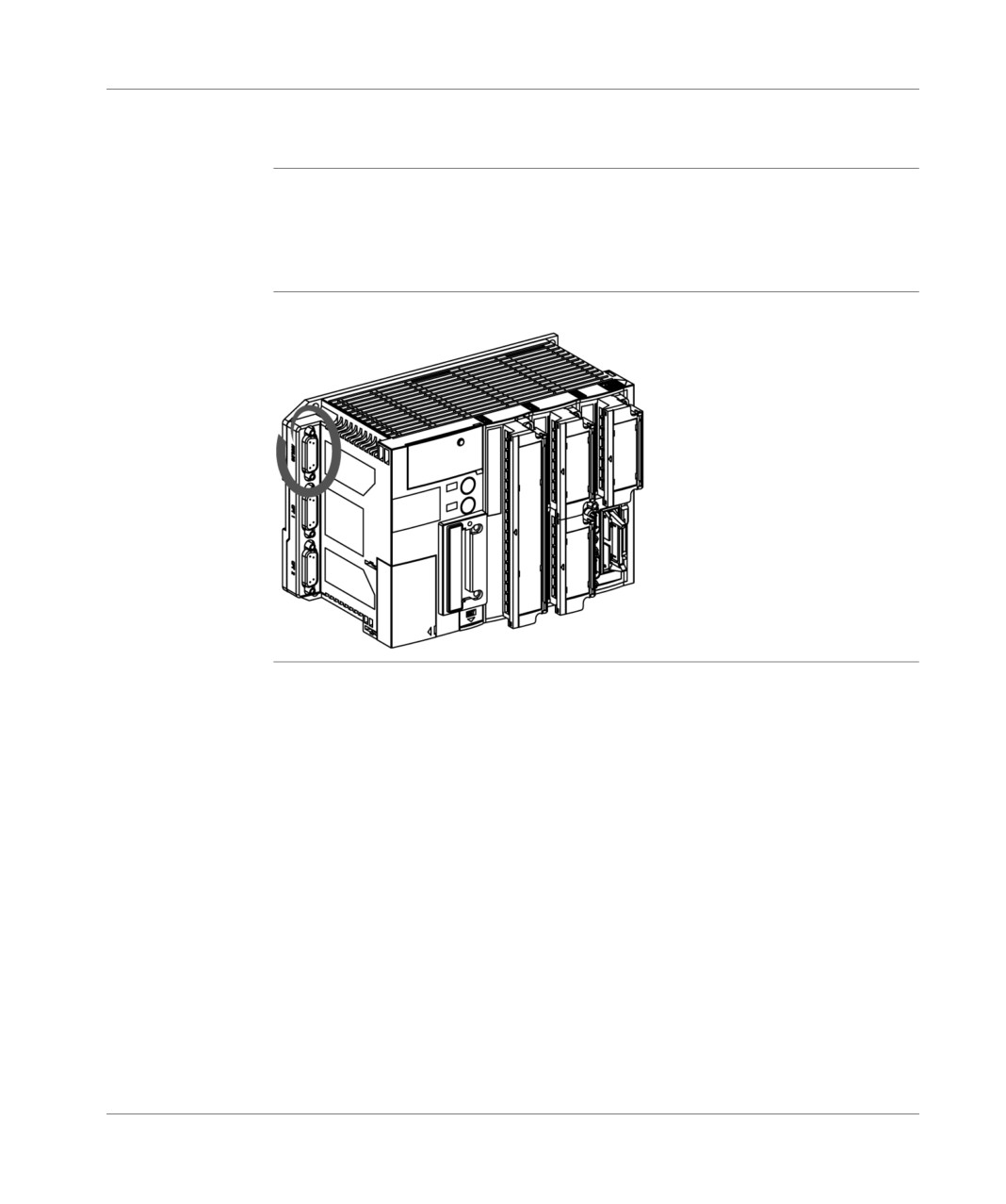
The TSX 37-22 PLC’s have built-in as standard an analog interface which comprises
8 input channels and one output channel. This interface makes it possible to
respond to applications which require analog processing but where the performance
and the characteristics of an analog measurement system cannot be justified.
Illustration
Diagram of a TSX 37 with evidence of the analog connector:
204
TSX DM 37 xxE
Overview of the built-in analog interface
Functions
At a Glance
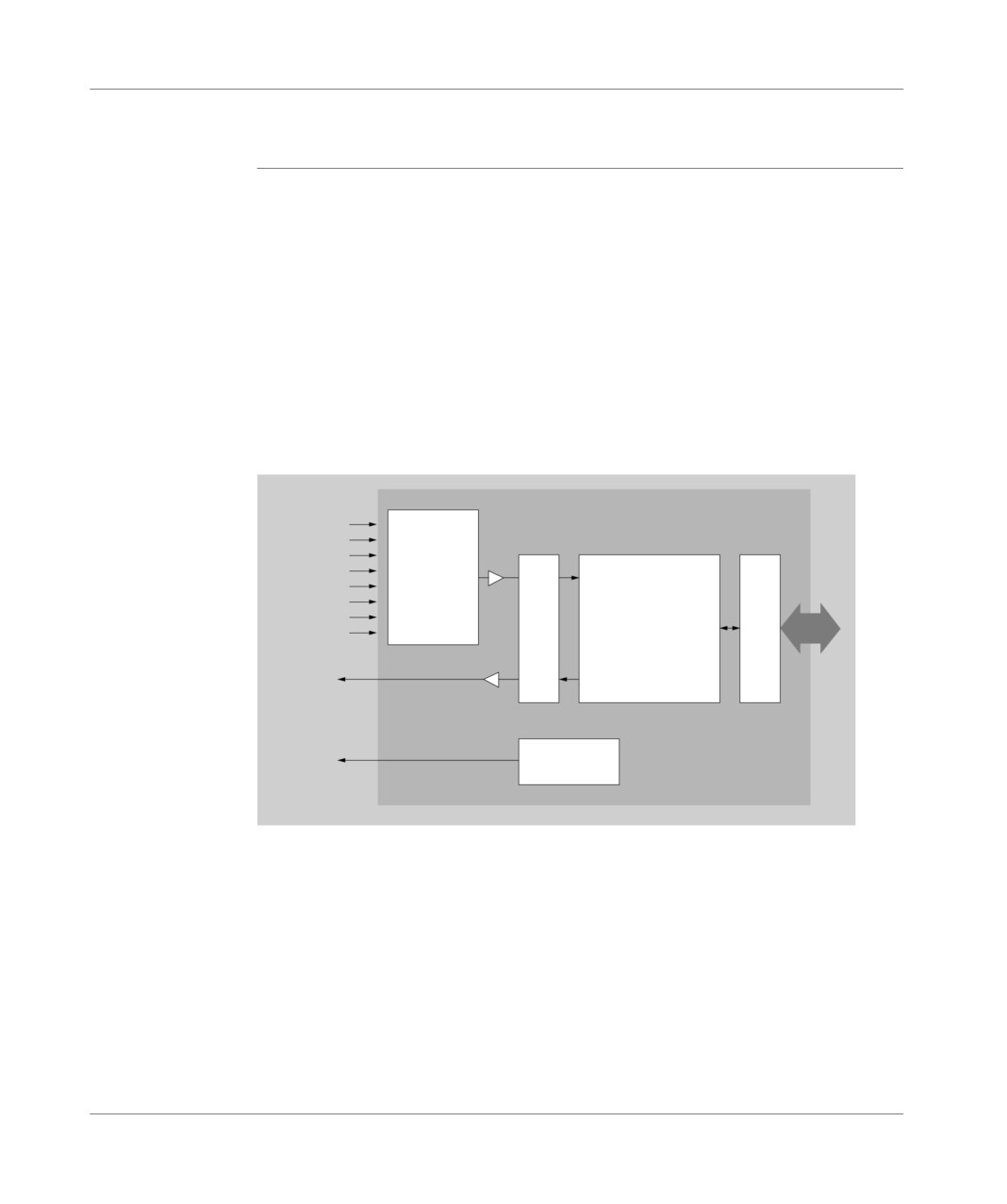
This interface which can be accessed via a Sub-D 15-pin connector, carries out the
following functions:
polling of input channels by static multiplexing and value aquisition,
analog/digital conversion of input measurements,
filtering of input measurements,
updating of digital output value by the processor,
digital/analog conversion of the output value,
processing of dialog errors with the processor and especially the fallback setting
of the output,
the provision of a reference voltage for the external sliders, or those contained in
the TSX ACZ 03 adjustment and adaptation module.
Illustration:
2
3
Convert
Processing
4
8 inputs
5
Overrun
Multiplexor
A/N
Sensor control
0-10V
6
7
filtering
8
Display
Interf.
9
bus
1 output
Update
0-10V
N/A
Error processing
1 output
voltage
ref.10V
reference
The TSX ACZ 03 module (See TSX ACZ 03 adjustment and adaptation module,
p. 219), assigned to the analog interface, makes it possible to:
have 4 sliders which enable you to adjust the 4 constants in one application
ergonomically and flexibly,
transform, via built-in shunts (499 Ω), the 0-10V inputs into 0-20mA or 4-20mA
inputs,
transform ,via built in adapters, analog inputs into discrete 24V (IEC type 1 or
Telecontrol 2-wire DDP) inputs.
TSX DM 37 xxE
205
Overview of the built-in analog interface
Using the TELEFAST pre-cabling system (ABE-7CPA01) (See Using the
TELEFAST pre-wiring system, p. 211), whether or not it is assigned to the TSX ACZ
03 module, makes input/output connection easier by providing screw terminal
blocks. It also makes connecting PLC discrete inputs/outputs easier if the analog
output is used to control a variable controller.
206
TSX DM 37 xxE
Overview of the built-in analog interface
Characteristics of the built-in analog inputs
General points
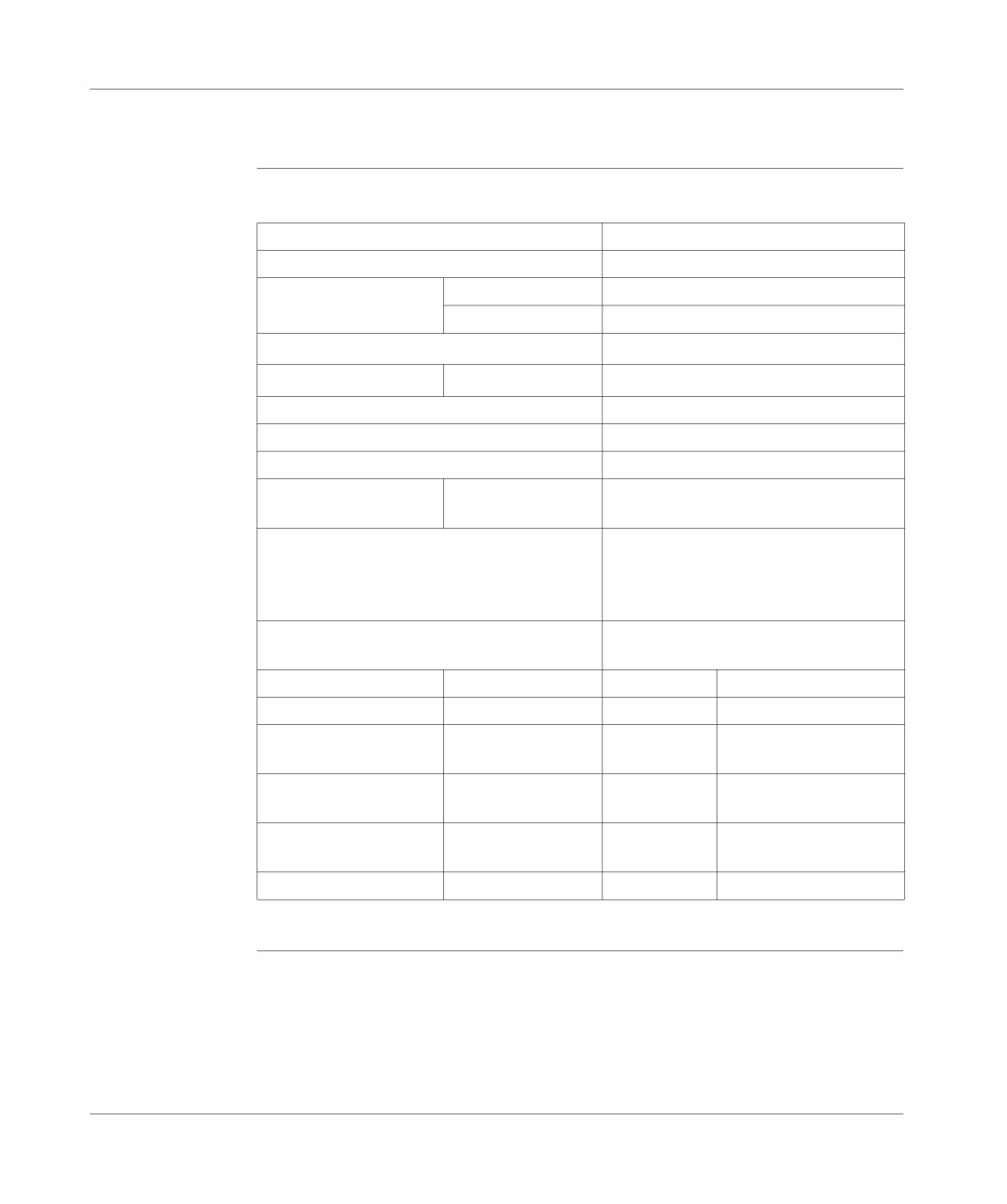
Data table:
Numbers of channels
8
Analog/Digital conversion
8 bits (256 pin) successive approximation
Acquisition cycle time
Normal cycle
32 ms
Fast cycle
4 ms x Number of channels used
Digital filtering
1st order. Configurable time constant
Hardware filtering
1st order. Cut-off frequency #600 Hz
Insulation between channels and ground
None (shared linked to ground)
Insulation between channels
Shared pulse
Insulation between bus and channels
None (shared linked to 0 V of the bus)
Input impedance
54 kOhms (0-10 V)
499 Ohms (0-20 mA or 4-20 mA)
Maximum voltage surge authorized on inputs
0-10 V: +30 V/-15 V over 3 channels
(PLC on or off)
simultaneously
0-20 mA (1): +/-15 V or +/-30 mA over 1
channel
Standards
IEC 1131 (0-10 V inputs) - UL508
ANSI MC96.1 - NF C 42-330
Electric range
0-10 V
0-20 mA (1)
4-20 mA (1)
Full scale (FS)
10 V
20 mA
20 mA
Resolution
40 mV (250 pulses)
80 µA
80 µA
(250 pulses)
(250 pulses)
Max. error at 25°C
1.8% FS = 180 mV
2.8% FS = 560
2.8% FS = 560 µA
µA
Max. error at 60°C
4% FS = 400 mV
5.6% FS =
5.6% FS = 1.12 mA
1.12 mA
Temperature drift
0.75%/10°C
0.80%/10°C
0.80%/10°C
(1) with TSX ACZ 03 adjustment module.
TSX DM 37 xxE
207

Overview of the built-in analog interface
Built-in analog output feature
General
Data table:
Number of channels
1
Analog/Digital conversion
8 bits (256 pulses)
Response time
50 micro seconds
Insulation between channels and
None (share linked to ground)
ground
Insulation between bus and channels
None (share linked to 0V of the bus)
Max voltage surge authorized on the
Short-circuit at 0V or at +5V
output
Protection
Permanent short circuit
Norms
IEC 1131 - UL508 - ANSI MC96.1 - NF C 42
-
330
Electric range
0-10V
Full scale (FS)
10V
Resolution
40mV (250 pulses)
Max. error at 25°C
1.5% PE = 150mV
Max. error at 60°C
3% PE = 300mV
Load impedance
>= 5 kOhms
Temperature drift
0.5 % / 10°C
Reference output
data table:
feature (slider
Voltage value
10V
supply)
Maximum current load (1)
10mA
Max. error at 25°C
3.9% PE = 390mV
Max. error at 60°C
6% PE = 600mV
Protection
Permanent short circuit
Temperature drift
1% / 10°C
(1) the total number of sliders is therefore limited to 4, whether they are inside the
TSX ACZ 03 module, or external sliders.
208
TSX DM 37 xxE
Connecting the built in interface
22
At a Glance
Aim of this
This chapter deals with connecting the built in analog interface.
chapter
What's in this
This Chapter contains the following Maps:
Chapter?
Topic
Page
Direct connection of the analog interface
210
Using the TELEFAST pre-wiring system
211
Connecting analog inputs with insulated or non-insulated sensors
213
Connecting analog output and external sliders
214
Connecting a variable speed controller
215
Details of wiring the ALTIVAR 16
216
ABE-7CPA01 analog TELEFAST internal wiring
218
TSX DM 37 xxE
209
Connection
Direct connection of the analog interface
General
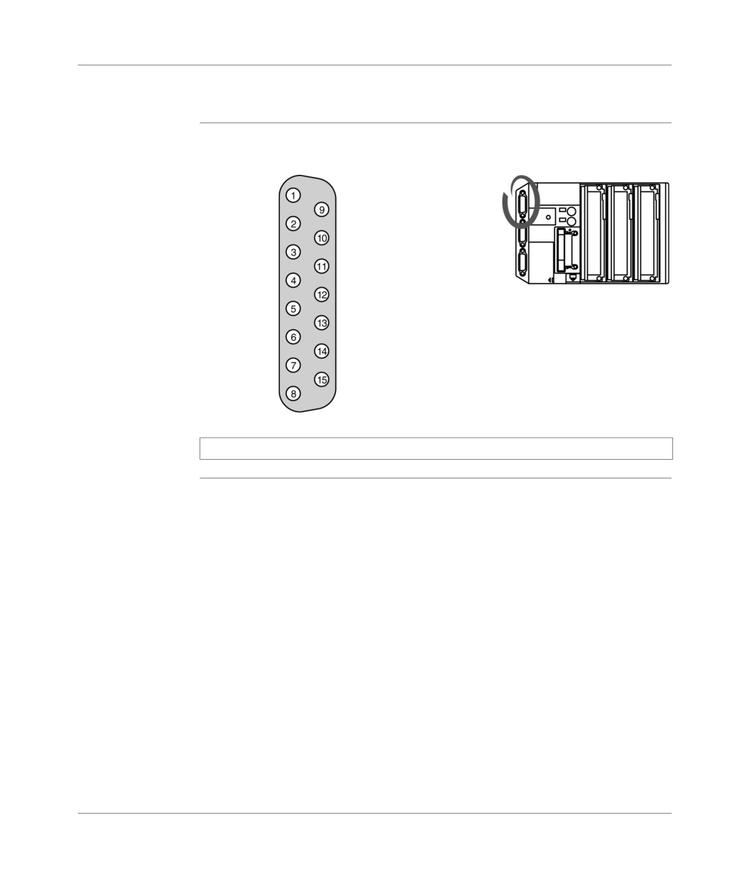
The analog interface can be accessed via a 15-pin SUB-D connector, of which the
pin configuration is as follows:
Output 10
NC
Shared
outputs
Input 2
Input 3
Input 4
Input 5
Input 6
Input 7
Input 8
Input 9
Shared inputs
NC
10V reference output
NC
Note: The inputs are numbered from 2 to 9.
210
TSX DM 37 xxE
Connection
Using the TELEFAST pre-wiring system
General points
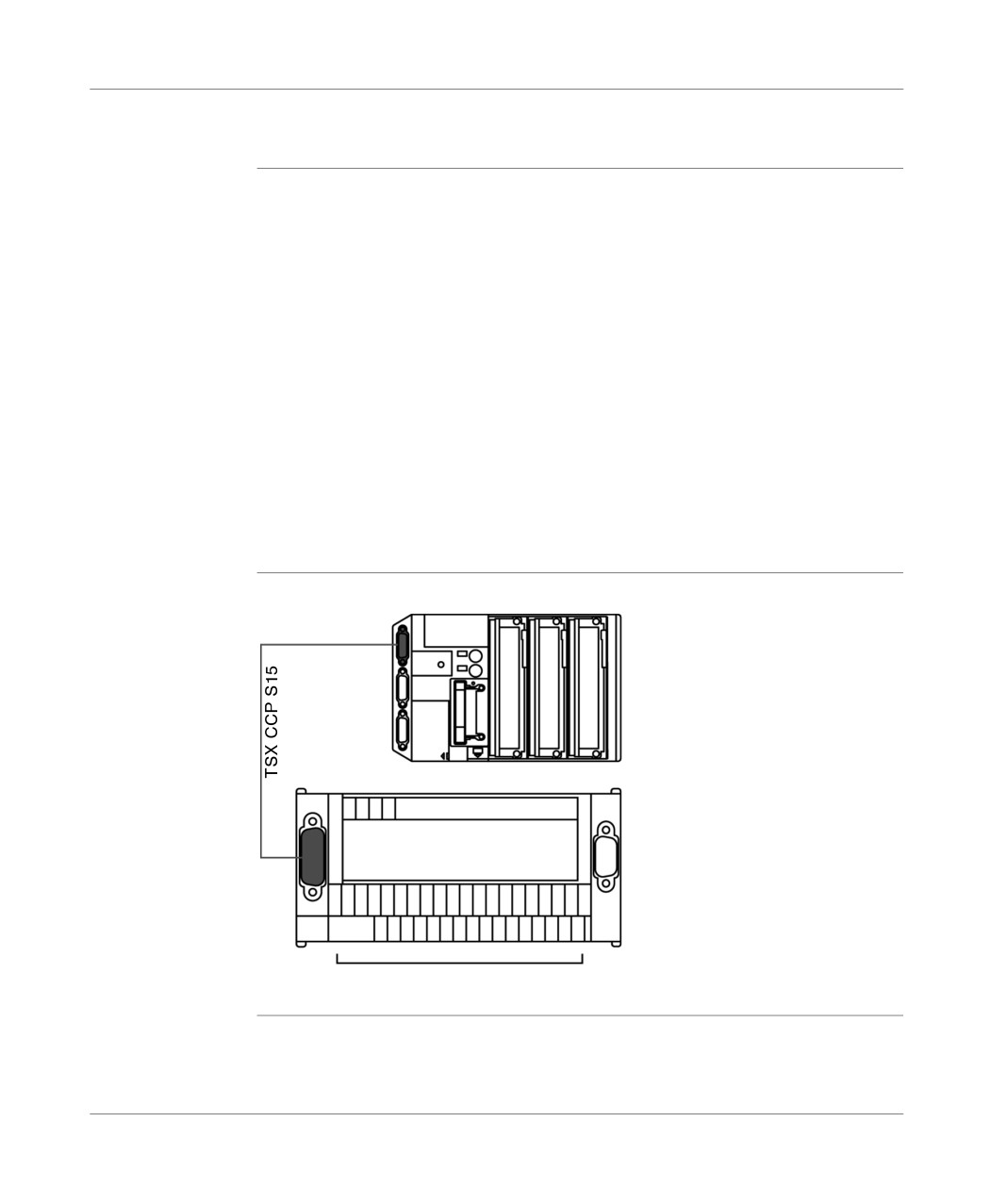
Using the TELEFAST pre-wiring system, with reference ABE-7CPA01, facilitates
the implementation of the built-in analog function. It provides access to all the inputs/
outputs required by the built-in analog function via screw terminals:
8 analog inputs,
1 analog output,
1 10 V reference output for the external sliders (4 max.).
The PLC is connected to the TELEFAST system via a 2.5m cable, with product
reference TSX CCP S15.
The TELEFAST system also offers a female 9-pin SUB-D connector which makes it
possible to directly control an ALTIVAR 16 variable speed controller (see
Connecting a variable speed controller, p. 215).
Having taken the impedance of the analog inputs into account, we recommend that
you use sliders with a value of 4.7 kΩ, which limits the number of sliders to 4
(maximum current from the reference output = 10 mA).
Illustration
Principle diagram:
TELEFAST ABE-7CPA01
Analog I/O
TSX DM 37 xxE
211
Connection
Terminals of pre-
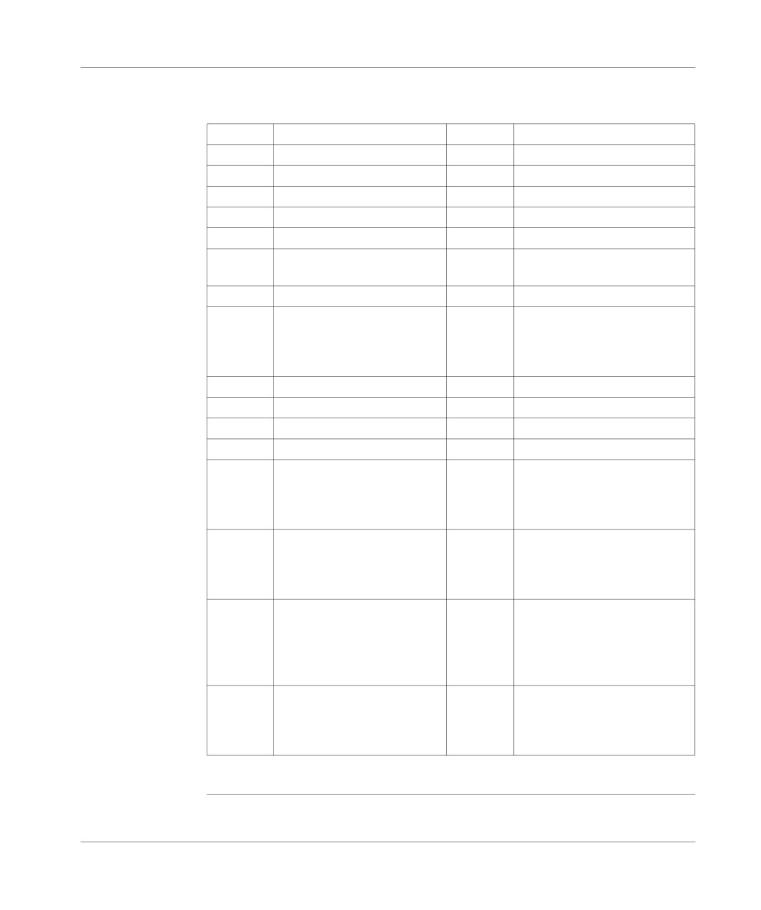
The table below gives a description of the terminals of the TELEFAST ABE-7CPA01
cabling system
pre-cabling system:
TELEFAST ABE-
Terminal
Function
Terminal
Function
7CPA01
1
Shared (0 V analog output)
17
Shared (0 V analog input) *
2
Analog output
18
Analog input 8
3
Shared (0 V analog output)
19
Shared (0 V analog input) *
4
NC
20
Analog input 9
5
Shared (0 V analog input) *
21
Shared (0 V analog input) *
6
Analog input 2
22
10 V Reference output for
external sliders
7
Shared (0 V analog input) *
23
Shared (0 V analog input)
8
Analog input 3
24
24 V supply provided by the
variable controller. It must be
connected to the terminal shared
by the PLC’s discrete outputs
9
Shared (0 V analog input) *
25
NC
10
Analog input 4
26
NC
11
Shared (0 V analog input) *
27
NC
12
Analog input 5
28
NC
13
Shared (0 V analog input)
29
Sharing the variable controller. It
must be connected to the shared
terminal of the PLC’s discrete
input
14
Analog input 6
30
"Forward" input of the variable
controller. It must be connected
to the discrete output terminal of
the PLC
15
Shared (0 V analog input) *
31
Safety output of the variable
controller.
It must be connected to one of
the PLC’s discrete input
terminals
16
Analog input 7
32
"Reverse" input of the variable
controller. It must be connected
to one of the PLC’s discrete
output terminals
* Terminals 21 and 23 must be linked to each other by an external wire strap.
212
TSX DM 37 xxE
Connection
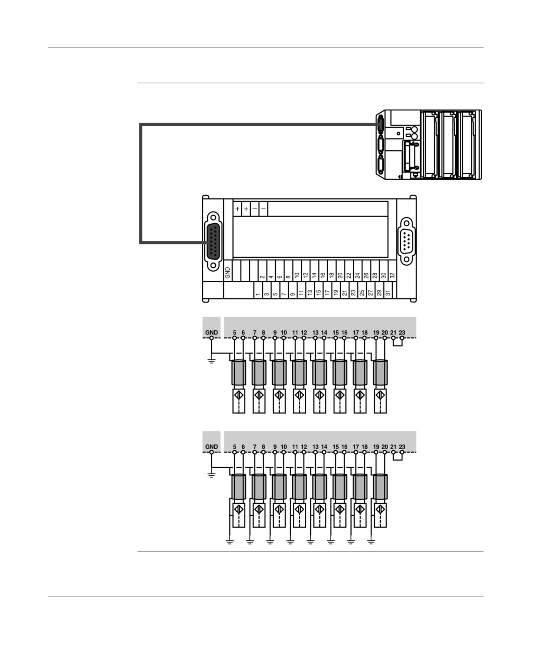
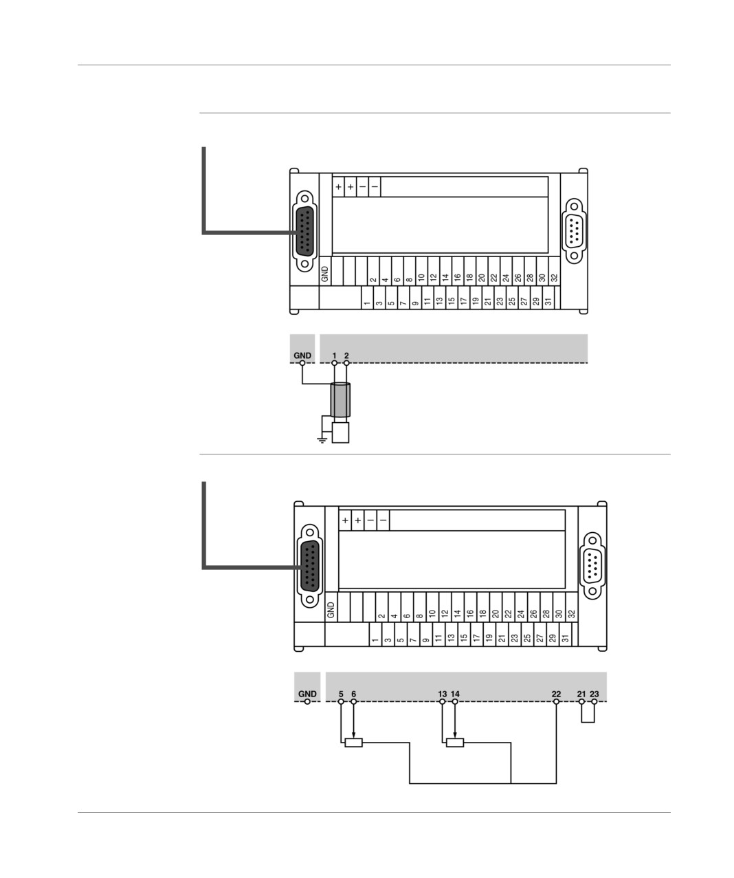
Connecting analog inputs with insulated or non-insulated sensors
Diagram
Illustration:
showing the
TSX CCP 515 cable
principle
TELEFAST ABE-7CPA01
Terminal bar
for grounding
L = several tens of
Sensors
meters
insulated
Terminal bar
for grounding
L = several meters
Sensors
non-insulated
TSX DM 37 xxE
213
Connection
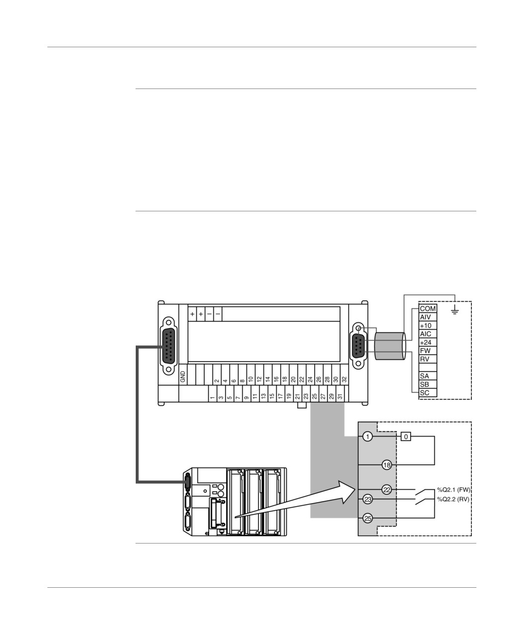
Connecting analog output and external sliders
Connecting
Illustration:
analog output
TSX CCP
TELEFAST ABE-7CPA01
515 cable
Pre-actuator
0-10V analog
Connecting
Illustration:
external sliders
TSX CCP 515
TELEFAST ABE-7CPA01
cable
214
TSX DM 37 xxE
Connection
Connecting a variable speed controller
General
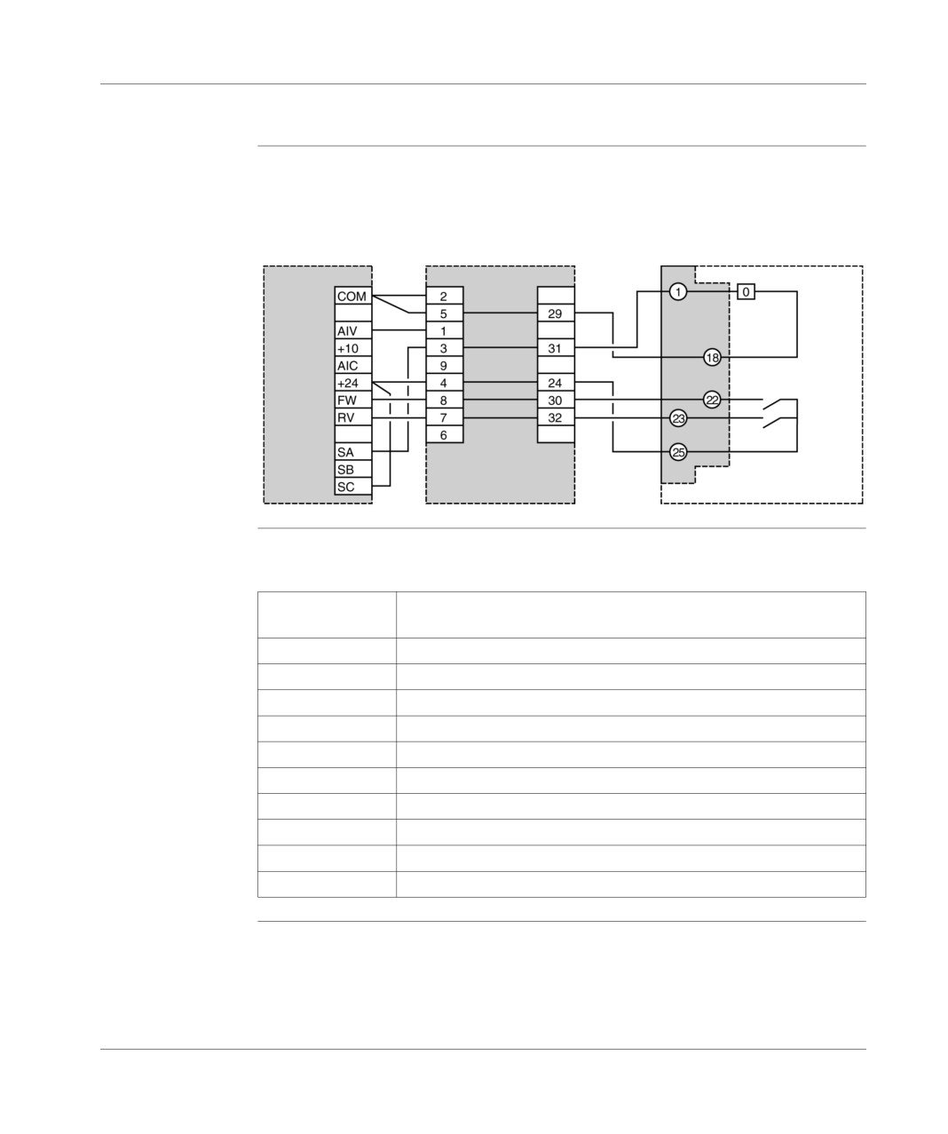
The TELEFAST ABE-7CPA01 cabling system makes it possible to use the inputs/
outputs from a discrete PLC module, in order to control an ALTIVAR 16 variable
speed controller:
2 discrete outputs, used as command inputs at the front and the back of the
controller (forward and reverse commands),
1 discrete input used to signal a fault in the controller to the PLC.
The variable speed controller can be connected directly via the female 9-pin Sub-D
controller from the TELEFAST system and the TSX CDP 611 cable.
Illustration
The following figure illustrates the example of a variable speed controller’s wiring,
controlled by a TSX DMZ 28DR module, situated in the first PLC slot. Outputs 1 and
2 of the discrete module give commands to the ALTIVAR and its 0 input serves as
a copy of the variable speed controller safety relay:
ALTIVAR
TELEFAST ABE-7CPA01
CABLE
TSX
CDP 611
Discrete I/O
TSX CCP 515 cable
Input
%I1.0
(variable
speed
controller
fault)
Outputs
Ex TSX DMZ 28DR
TSX DM 37 xxE
215
Connection
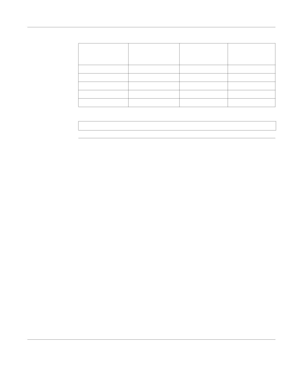
Details of wiring the ALTIVAR 16
Principle
Illustration:
diagram
TELEFAST ABE-7CPA01
ALTIVAR
Screw
SubD 9 pts
terminal block
Discrete inputs/outputs
Inputs
Outputs
Ex. TSX DMZ 28DR
ALTIVAR 16
The following table provides a reminder of the different functions of the ALTIVAR 16
terminal block
terminal block:
functions
Terminal block
Functions
address
COM
Common to speed monitoring inputs and control inputs.
AIV
Speed monitoring input on.
+10
Supply for speed monitoring inputs.
AIC
Speed monitoring input running.
+24
Supply for control inputs (60 mA).
FW
Forwards control input.
RV
Reverse control input.
SA
"O" contact on the safety relay.
SB
"F" contact on the safety relay.
SC
Shared safety relay contact.
216
TSX DM 37 xxE
Connection
Marking of TSX
Data table:
CDP 611 cable
TELEFAST terminal
TSX CDP 611 cable
TELEFAST terminal
TSX CDP 611 cable
wires
block (terminal
(wire color)
block
(wire color)
number)
(terminal number)
1
black
6
blue
2
white
7
orange
3
red
8
yellow
4
green
9
violet
5
brown
Note: the cable shielding must be mated with the TELEFAST ground terminal.
TSX DM 37 xxE
217
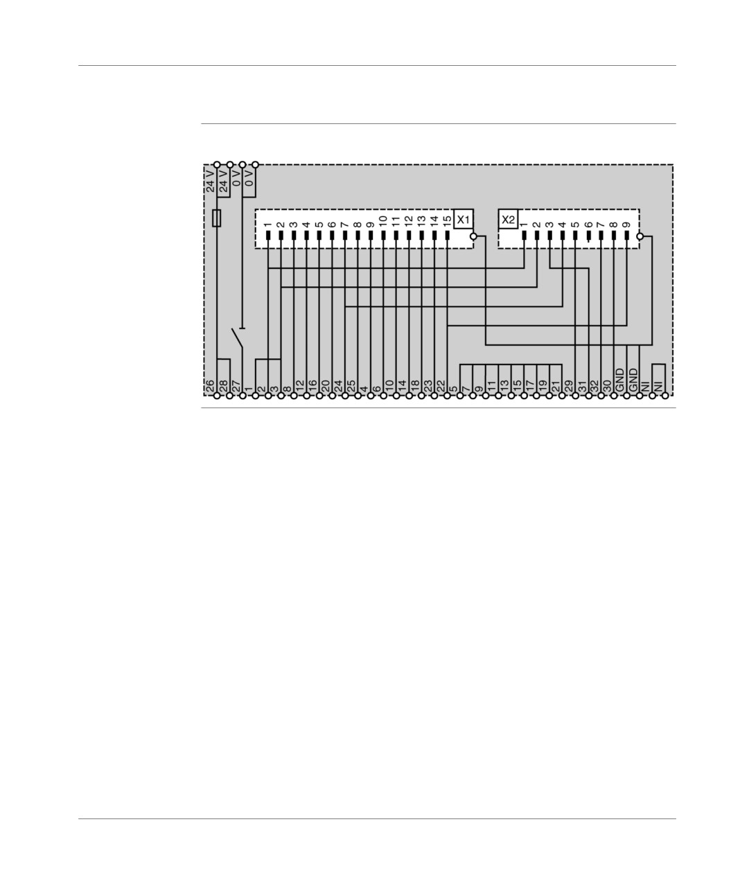
Connection
ABE-7CPA01 analog TELEFAST internal wiring
Diagram
Illustration:
showing the
principle
15-pin sub-D
9-pin sub-D
218
TSX DM 37 xxE
TSX ACZ 03 adjustment and
adaptation module
23
At a Glance
Aim of this
This chapter deals with the TSX ACZ 03 module and its implementation.
chapter
What's in this
This Chapter contains the following Maps:
Chapter?
Topic
Page
TSX ACZ 03 adjustment and adaptation module: at a glance
220
Module standard functions
222
Module implementation
224
Selecting the function carried out by the module
227
TSX DM 37 xxE
219
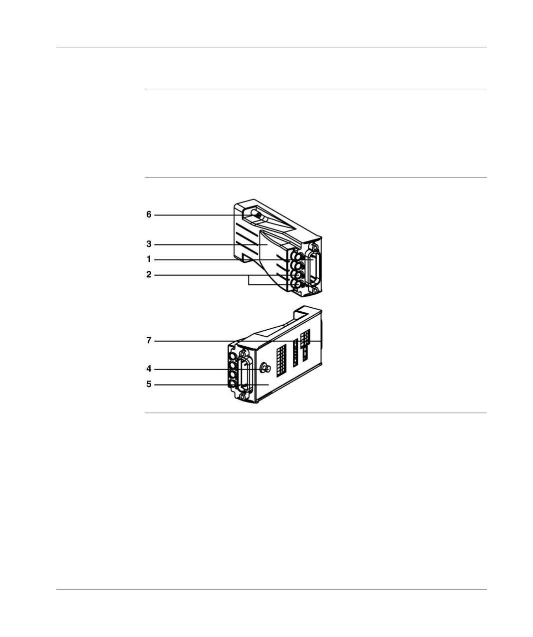
TSX ACZ 03 module
TSX ACZ 03 adjustment and adaptation module: at a glance
Introduction
The TSX ACZ 03 module completes the functions offered by the analog inputs which
are built in to the TSX 37-22 PLC’s, by enabling:
manual adjustment of the application program values via internal (first 4 inputs)
or external sliders,
current conversion (0-20mA or 4-20mA) of signals 0-10V of each of the inputs,
adapting each analog input to a discrete 24V input.
Illustration
TSX ACZ 03
220
TSX DM 37 xxE

TSX ACZ 03 module
Addresses table Addresses and description:
Address
Description
1
Connector enabling external connections. This connector is identical (same
type and same connector) to the PLC connector.
2
Adjustment sliders of the first 4 inputs.
3
Plastic module body.
4
Module maintenance pinfeed.
5
Metal plaque which allows access to reversing switches and microswitches.
6
Screw to fix the module to the PLC.
7
Connector for connecting the module to the PLC.
TSX DM 37 xxE
221
TSX ACZ 03 module
Module standard functions
Introduction
For each of these inputs, the standard functions offered by the TSX ACZ 03 module
are as follows:
1 Transfer of
The 0-10V analog inputs (See Characteristics of the built-in analog inputs, p. 207),
analog input to
the output and the reference voltage, available on the PLC connector, are
the module
transferred to the connector on the front of the TSX ACZ 03 module, with the same
connector
connector (see Direct connection of the analog interface, p. 210).
2 Input signal
The input signal (setpoint, threshold, timer, etc.) is chosen by using an internal slider
adjustments
for the first 4 inputs, and an external one for the other inputs (transfer of unused
channels onto the upper connector).
A reference output (See Reference output feature (slider supply), p. 208) is supplied
by the PLC to supply the internal sliders (for a maximum of 4 inputs).
3 Conversion of
A powered channel is chosen (See Characteristics of the built-in analog inputs,
the input in the 0-
p. 207) by positioning a microswitch on the module, after adaptation has been
20 mA or 4-20 mA
carried out by joining on a 499 Ω 1% resistor.
range.
A current range is chosen from the 2 possible options (0-20 mA or 4-20 mA) when
the software is configured.
222
TSX DM 37 xxE

TSX ACZ 03 module
4 Conversion of
The analog input can be converted into a 24 V discrete input (IEC Type 1 or
the analog input
Telemecanique 2-wire DDP compatible) on the 8
input channels, independently of
into 24 V discrete
each other.
input
The inputs have the following electric features:
Designation
Characteristics
Rated voltage: One
24 V
Voltage limits:
U1 (ripple included) (1)
19 to 30 V
U max (2)
34 V
24 V rated current
8 mA
Input impedance
2.67 kOhms
Voltage for "ON" status: Uon
≥11 V
Current in Uon = 11 V: Ion
≥ 2.5 mA
Voltage for "OFF" status: Uoff
≤ 5V
Current in "OFF" status
≤ 1.4 mA
OFF/ON filtering time
1 to 1.5 ms
ON/OFF filtering time
200 to 300 micro seconds
Jitter due to the
Normal cycle
32 ms
acquisition time of
Fast cycle
4 ms x Number of channels used
analog inputs
IEC 1131 compatibility with sensors
Type 1
Compatibility with 2-wire DDP
Telemecanique
Compatibility with 3-wire DDP
Yes
Input type
Resistive
Logic type
Positive
Insulation between channels
None (0 V shared between
channels)
Insulation between channels and ground
None (0 V linked to ground)
(1) The point-to-point ripple must be less than 5% of the rated voltage.
(2) Standard function limited to 1 hour/24 hours.
TSX DM 37 xxE
223
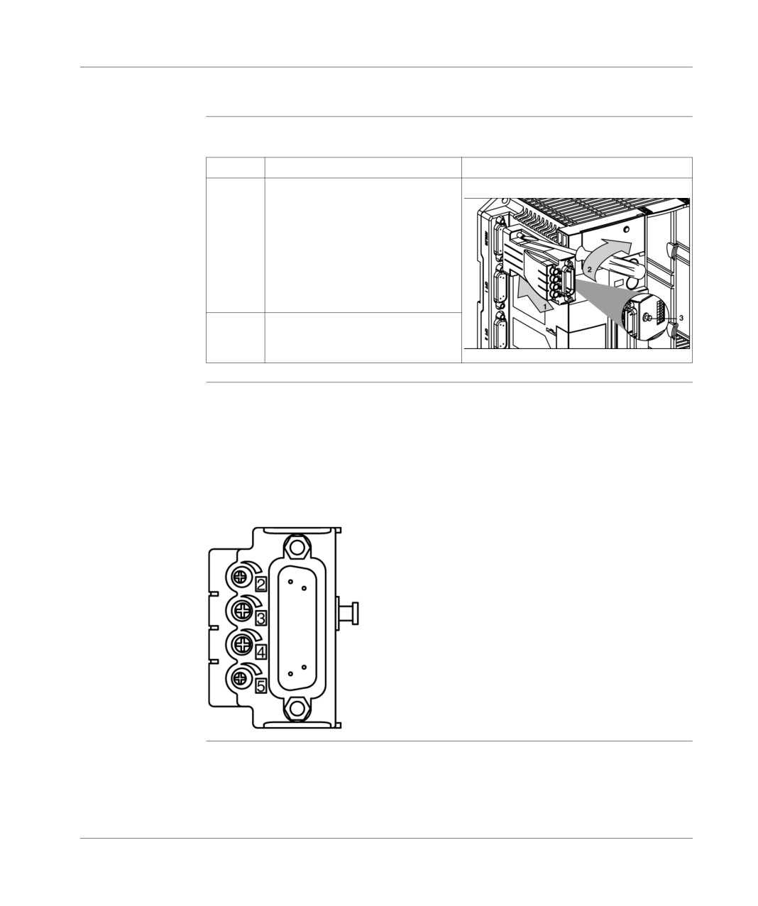
TSX ACZ 03 module
Module implementation
Mounting the
Carry out the following steps:
module
Step:
Action
Illustration
1
Connect the module to the analog
interface which is built in to the TSX
37-22 PLC (first connector). This
operation can be carried out when
the PLC is on or off. The module is
maintained on the front panel by the
pinfeed (3) which clips onto the side
panel of the PLC.
2
Attach the module with its 2 fixing
screws.
Using the
The first 4 inputs are fitted with an internal slider which makes it possible to adjust,
internal sliders
for example a setpoint, or a threshold. To do this, set the C1 and C2 input switches
to 0, and C3 and C4 to 1. Then adjust the corresponding slider to vary the input
voltage (between 0 and 10V)
The internal sliders on the first 4 inputs are accurate to +/- 20%.
Illustration:
224
TSX DM 37 xxE
TSX ACZ 03 module
Connecting the
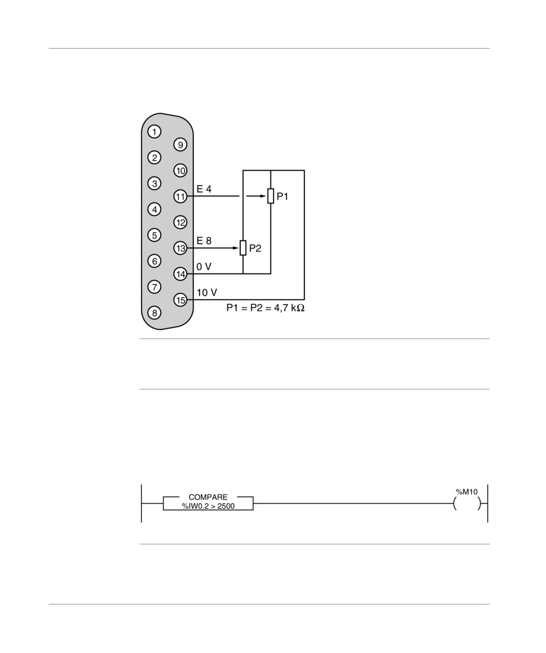
Wiring a slider on an input makes it possible to vary its value between 0 and 10V,
external sliders
for example, to adjust a setpoint or a threshold. The recommended value of this
slider is 4.7kΩ.
Example: wiring an external slider on inputs 4 and 8.
Usage at 0-20mA Each input can be configured individually as an actual input. To do this, set the
or 4-20mA
corresponding C2 switch to 1 (when the other switches are at 0) and configure the
chosen range using software. 0-20mA or 4-20mA.
Converting to
Each input can be individually configured as a type 1, 24V discrete input or 2-wire
discrete inputs
DDP. To do this, set the corresponding C1 switch to 1 (when the other switches are
at 0) and define, using an application program, the discrete input threshold value:
this threshold is set at 2500.
Choose the 0-10V voltage range in the software configuration.
Example, we want to use input 2 as a discrete input.
The %M10 bit will be at 0 or at 1 according to the status of the discrete input.
TSX DM 37 xxE
225
TSX ACZ 03 module
Connecting the
It is carried out via the 15-pin Sub-D connector available on the module, of which the
external sensors
pin configuration is identical to that of the analog interface connector which is built
and pre-
in to the PLC.
actuators
226
TSX DM 37 xxE
TSX ACZ 03 module
Selecting the function carried out by the module
General points
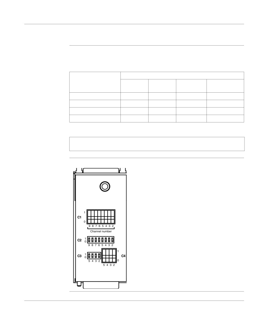
The selection is made for each of the input channels (channels 2 to 9), via the
reversing switches and micro-switches which can be accessed on the module (on
the metal plate side):
Reversingswitches and
Functions
micro-switches
0-10 V
Range
Adjustment
Discrete input
range (*)
0/4-20 mA
of int. slider
C1
0
0
0
1
C2
0
1
0
0
C3
0
0
1
0
C4
0
0
1
0
(*) Factory-adjusted.
Note: The table is identical for channels 2 to 5. Channels 6 to 9 do not have the
"Internal slider" function.
Illustration
TSX ACZ 03:
TSX DM 37 xxE
227
TSX ACZ 03 module
228
TSX DM 37 xxE
Counting built into bases
VI
At a Glance
Aim of this tab
This tab deals with the built-in counting function on TSX Micro.
What's in this
This Part contains the following Chapters:
part?
Chapter
Chaptername
Page
24
Overview of built-in counting function
231
25
Overview of different counting functions
235
26
Counting functions on (500Hz) discrete inputs
239
27
Up counting functions built in to (10KHz) TSX 37 22 bases
247
28
Implementing 500Hz up counting on discrete inputs
259
29
Implementing 10KHz upcounter onto TSX 37-22 bases
271
30
Appendices
291
TSX DM 37 xxE
229
Counting built into bases
230
TSX DM 37 xxE
Overview of built-in counting
function
24
At a Glance
Aim of this
This chapter describes the built-in counting function on the TSX Micro.
chapter
What's in this
This Chapter contains the following Maps:
Chapter?
Topic
Page
500Hz counts on the discrete inputs of TSX 37 bases
232
Built in 10 KHZ counting function on TSX 37 22 bases
233
TSX DM 37 xxE
231
Overview of built-in counting function
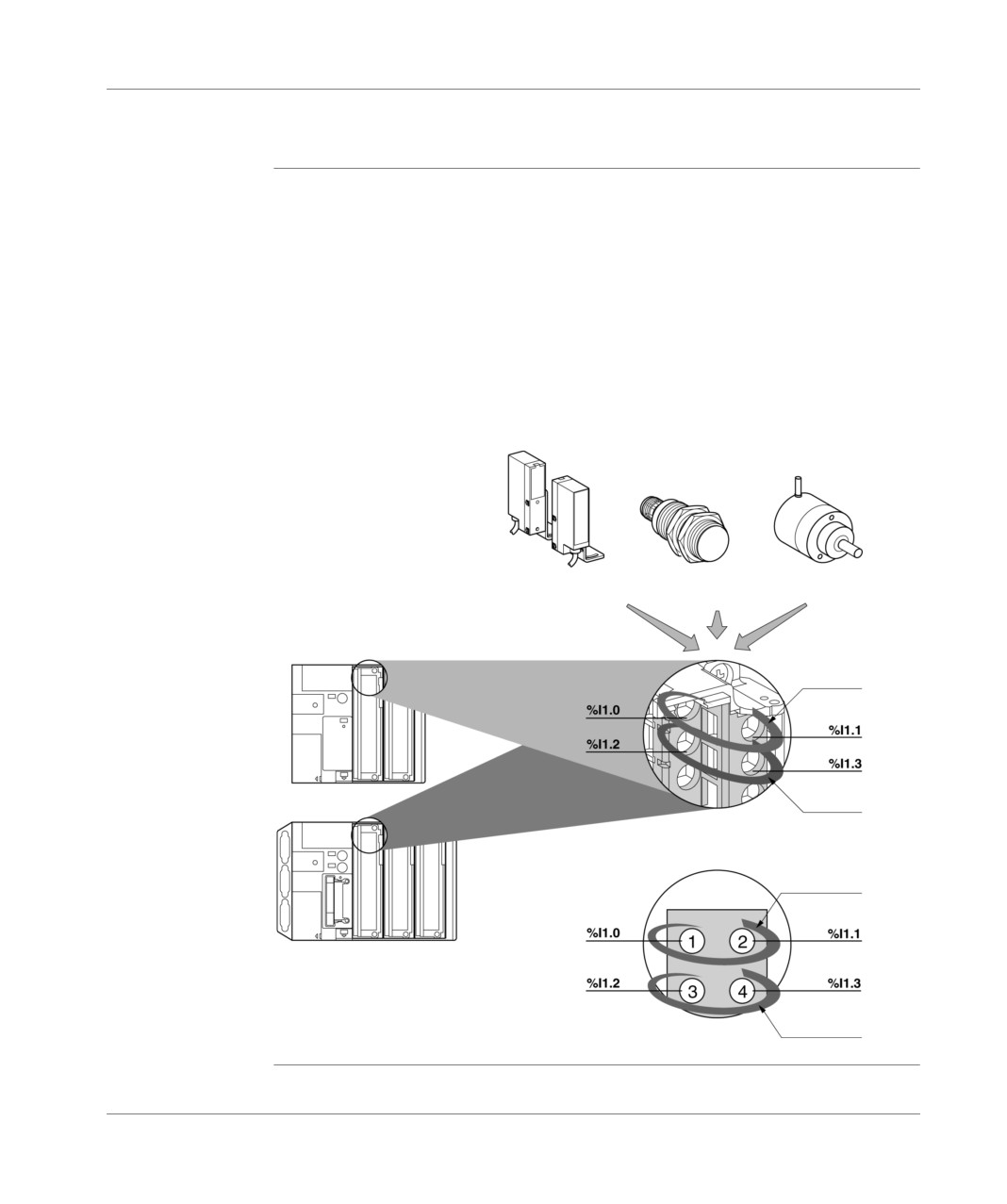
500Hz counts on the discrete inputs of TSX 37 bases
General points
On TSX 37 05/08 PLCs and TSX 37 10 or TSX 37 21/22 PLC bases, the first four
inputs of a discrete input/output module located in position 1 (%I1.0 to %I1.3) can
be used for counting up to a maximum frequency of 500Hz.
These four inputs allow a maximum of two independent counting channels, the
function settings (counting down, counting up, or counting up/down) are specified in
the software configuration.
There may be different kinds of sensor which generate the counting pulses (static
output or dry contact sensors) insofar as their outputs are compatible with the inputs
of the module.
Illustration:
Pulse generator/
Incremental encoder
Photoelectric detector
Proximity detector
TSX 37-10 PLC
Channel 0
Channel 1
Module with screw
terminal block
Channel 0
TSX 37-21 or 37-22 PLC
Channel 1
Module with HE10 connector
232
TSX DM 37 xxE
Overview of built-in counting function
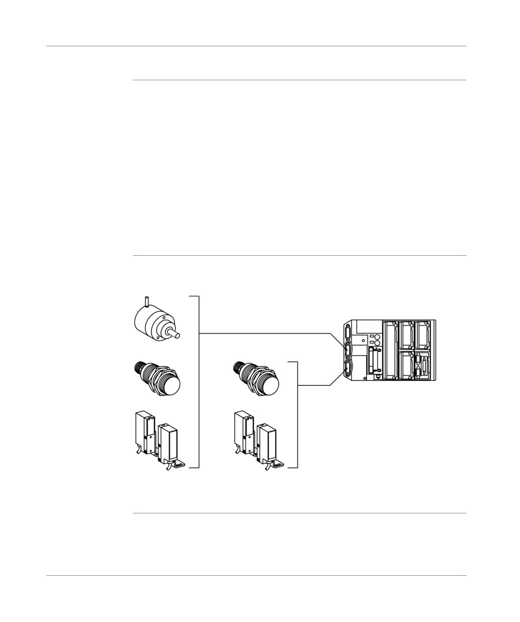
Built in 10 KHZ counting function on TSX 37 22 bases
General
The TSX 37 22 PLC bases incorporate counting interfaces which enable them to
carry out counting up, counting down or up/down counting functions at a maximum
frequency of 10KHz. These counting interfaces, which can be accessed via two
standard 15-pin SUB-D connectors, comprise two independent counting channels
(channel 11 and channel 12); the function settings (up counting, down counting or
up/down counting) are specified by software configuration.
The sensors which generate the counting pulses may be:
either with static outputs, in which case the maximum counting frequency can
reach 10 KHz,
or with dry contact outputs, in which case the immunity of the input receiving the
counting pulses is fixed at 4ms and the counting frequency is limited to 100Hz.
The sensor type is chosen when the counting channel is configured by the software.
Illustration
Diagram of different sensor-types:
Incremental encoder
CNT1
channel 11
CNT2
channel 12
TSX 37 22 PLC
Proximity detector
Photoelectric detector
TSX DM 37 xxE
233
Overview of built-in counting function
234
TSX DM 37 xxE
Overview of different counting
functions
25
At a Glance
Aim of this
This chapter describes the different counting functions:
chapter
counting down function,
counting up function,
up/down counting function.
What's in this
This Chapter contains the following Maps:
Chapter?
Topic
Page
Down counting function
236
Up counting function
237
Up/down counting function
238
TSX DM 37 xxE
235
Overview of different counting functions
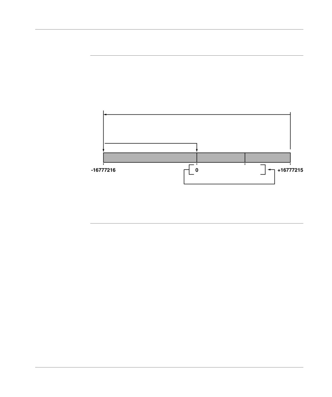
Down counting function
General points
The down counting function allows pulses to be counted down (on 24 bits + sign)
from a preset value between 0 and +16777215, and indicates when the current
value is equal to or less than 0.
The down counting range is between -16777216 and +16777215.
Illustration:
valid downcounting space
current measure value ≤ at 0
preset
with automatic preset
Operation of the down counting function, the language objects and the software
implementation are described in detail in the manual for the (Application-specific
functions, Volume 2, Upcouting Application).
236
TSX DM 37 xxE
Overview of different counting functions
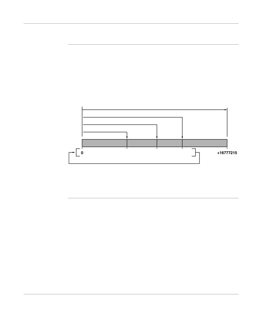
Up counting function
General points
The up counting function counts pulses (on 24 bits + sign) from 0 to a predefined
value known as the setpoint value.
The up counting range is between 0 and + 16777215. A signal is generated when
the setpoint value is passed.
The current value of the counter is always compared with two adjustable thresholds
(threshold 0 and threshold 1).
Illustration:
valid counting space
current value ≥ setpoint value
current value ≥ 1 threshold value
current value ≥ 0 threshold value
threshold 0
threshold 1
setpoint
with automatic reset to 0
Operation of the up counting function, the language objects and the software
implementation are described in detail in the manual for the (Application-specific
functions, Volume 2, Upcouting Application).
TSX DM 37 xxE
237
Overview of different counting functions
Up/down counting function
General points
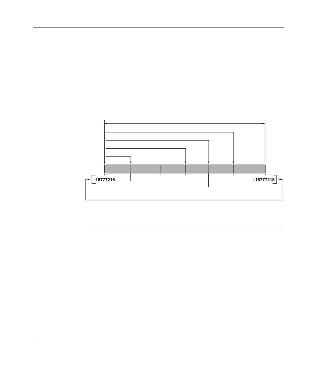
The up/down counting function carries out up and down counting pulses from the
same counter (on 24 bits + sign) from a preset value in the up/down counting range.
The up/down counting range is between -16777216 and +16777215 with the
possibility of defining two setpoints (a high and a low setpoint).
The current value of the counter is always compared with two adjustable thresholds
(threshold 0 and threshold 1).
Illustration:
valid upcounting/downcounting space
Current value ≥ with high setpoint
Current value≥ threshold 1
Current value≥ threshold 0
Current value ≥ with low setpoint
preset
setpoint
threshold 0
setpoint
high
low
threshold 1
Operation of the up/down counting function, the language objects and the software
implementation are described in detail in the manual for the (Application-specific
functions, Volume 2, Upcouting Application).
238
TSX DM 37 xxE
Counting functions on (500Hz)
discrete inputs
26
At a Glance
Aim of this
This chapter describes the counting functions on (500Hz) discrete inputs.
chapter
What's in this
This Chapter contains the following Maps:
Chapter?
Topic
Page
Introduction
240
Up counting or down counting
241
Up/down counting
243
TSX DM 37 xxE
239
Counting functions on (500Hz) discrete inputs
Introduction
General
The four discrete inputs (%I1.0 to %I1.3) of the module located in position 1 allow 2
independent up counting, down counting or up/down counting (channel 0 and
channel 1) channels to be made with a maximum frequency of 500Hz.
240
TSX DM 37 xxE
Counting functions on (500Hz) discrete inputs
Up counting or down counting
General points
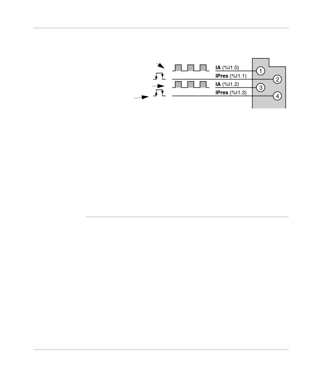
The up or down counting pulses are received on the inputIA (%I1.0 for channel 0
and %I1.2 for channel 1).
The inputIPres (%I1.1 for channel 0 and %I1.3 for channel 1) can be used:
either for setting the preset value of the current value for a down counting
function,
or for setting the current value to 0 for an up counting function.
Note:
symbol used in PL7-Micro screens for IPres input:
IPres if it is a down counting function,
IReset if it is an up counting function.
Setting to 0 (up counting) or setting the preset value (down counting) can be carried
out according to one of the methods described below:
when the status of the IPres input is changed (rising or falling edge, choice made
in configuration) and when this is validated in the software,
automatically as soon as:
the setpoint value has been reached in up counting,
the value 0 has been reached in down counting.
(choice made during configuration)
via software.
TSX DM 37 xxE
241
Counting functions on (500Hz) discrete inputs
Principle
Illustration:
Diagram
Module
in position 1
Channel 0 pulse input
Reset input to 0 or
preset channel 0
Channel 1 pulse input
Reset input to 1 or
preset channel 0
These functions can be used equally on the modules:
with a screw or HE10 connector terminal block,
with direct current inputs,
with alternating current inputs, in this case the up counting frequency is limited,
given the response time of this type of input.
If channel 1 is not used, the corresponding inputs can be configured into event, latch
state or normal discrete inputs. In this case, and if the inputs being used are supplied
by direct current, the immunity of these inputs will be defined for the inputs assigned
to up or down counting.
Channels 0 and 1 can be configured independently of one another, for example, with
one channel in up counting and the other in down counting or in up/down counting.
242
TSX DM 37 xxE