DL105 Micro PLC. User Manual (2003) - page 8
8-5
Maintenance and Troubleshooting
Program Error
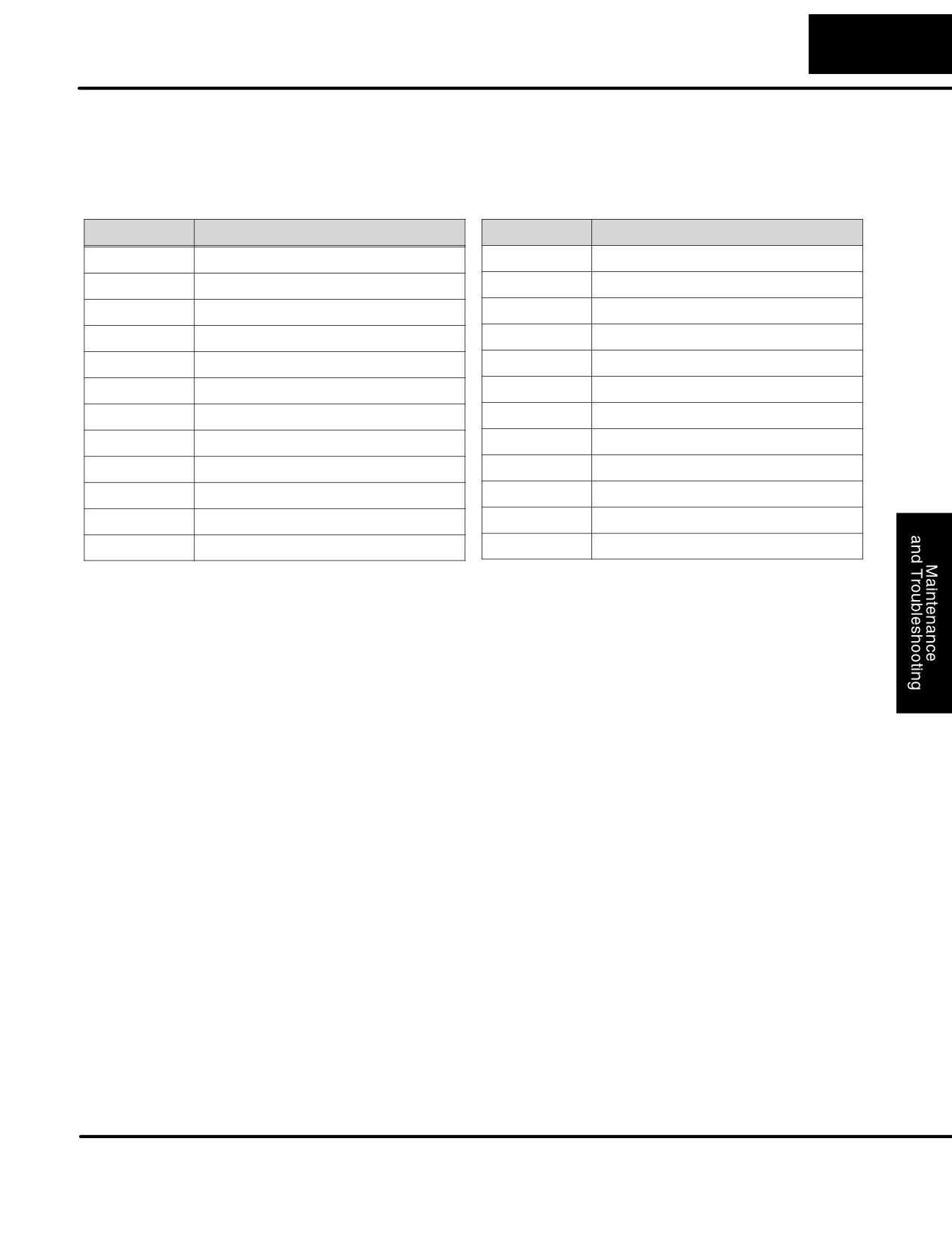
The following table lists program syntax and runtime error codes. Error detection
Codes
occurs during a Program-to-Run mode transition, or when you use AUX 21 - Check
Program. The CPU will also turn on SP52 and store the error code in V7755.
Appendix B provides a more complete description of the error codes.
Error Code
Description
Error Code
Description
E4**
No Program in CPU
E452
X input used as output coil
E401
Missing END statement
E453
Missing T/C
E402
Missing LBL
E454
Bad TMRA
E406
Missing IRT
E455
Bad CNT
E421
Duplicate stage reference
E456
Bad SR
E422
Duplicate SBR/LBL reference
E461
Stack Overflow
E431
Invalid ISG/SG address
E462
Stack Underflow
E436
Invalid INT address
E463
Logic Error
E438
Invalid IRT address
E464
Missing Circuit
E440
Invalid Data Address
E471
Duplicate coil reference
E441
ACON/NCON
E472
Duplicate TMR reference
E451
Bad MLS/MLR
E473
Duplicate CNT reference
DL105 PLC User Manual, 2nd Edition, Rev. A
8-6
Maintenance and Troubleshooting
CPU Indicators
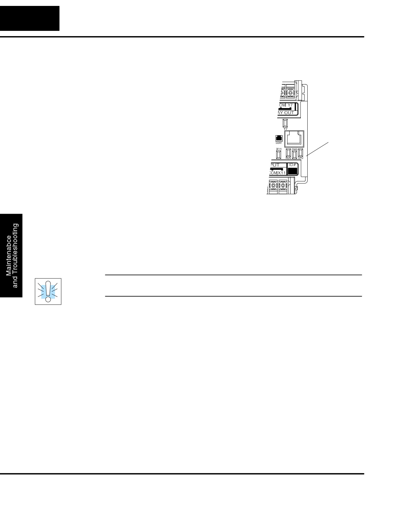
The DL105 Micro PLCs have indicators on the
front to help you diagnose problems with the
system. In normal runtime operation only the RUN
and PWR indicators are on. The table below is a
quick reference to potential problems.
Indicator Status Potential Problems
Run, Power, CPU
PWR (LED off)
1. System voltage incorrect
Indicators
2. PLC power supply faulty
RUN (LED off)
1. CPU programming error
2. (CPU in program mode)
CPU (LED on)
1. Electrical noise interference
2. Internal CPU defective
PWR Indicator
In general there are three reasons for the CPU power status LED (PWR) to be OFF:
1. Power to the unit is incorrect or is not applied.
2. PLC power supply is faulty.
3. Other component(s) have the power supply shut down.
If the voltage to the power supply is not correct, the PLC may not operate properly or
may not operate at all. Use the following guidelines to correct the problem.
WARNING: To minimize the risk of electrical shock, always disconnect the system
power before inspecting the physical wiring.
1. First, disconnect the external power.
2. Verify that all external circuit breakers or fuses are still intact.
3. Check all incoming wiring for loose connections. If you’re using a separate
termination block, check those connections for accuracy and integrity.
4. If the connections are acceptable, reconnect the system power and verify
the voltage at the DL105 power input is within specification. If the voltage is
not correct shut down the system and correct the problem.
5. If all wiring is connected correctly and the incoming power is within the
specifications, the PLC internal supply may be faulty.
The best way to check for a faulty PLC is to substitute a known good one to see if this
corrects the problem. The removable connectors on the DL105 make this relatively
easy. If there has been a major power surge, it is possible the PLC internal power
supply has been damaged. If you suspect this is the cause of the power supply
damage, consider installing an AC line conditioner to attenuate damaging voltage
spikes in the future.
DL105 PLC User Manual, 2nd Edition, Rev. A
8-7
Maintenance and Troubleshooting
RUN Indicator
If the CPU will not enter the Run mode (the RUN indicator is off), the problem is
usually in the application program, unless the CPU has a fatal error. If a fatal error
has occurred, the CPU LED should be on. (You can use a programming device to
determine the cause of the error.)
Both of the programming devices, Handheld Programmer and DirectSOFT32, will
return an error message describing the problem. Depending on the error, there may
also be an AUX function you can use to help diagnose the problem. The most
common programming error is “Missing END Statement”. All application programs
require an END statement for proper termination. A complete list of error codes can
be found in Appendix B.
If the CPU indicator is on, a fatal error has occurred in the CPU. Generally, this is not
CPU Indicator
a programming problem but an actual hardware failure. You can power cycle the
system to clear the error. If the error clears, you should monitor the system and
determine what caused the problem. You will find this problem is sometimes caused
by high frequency electrical noise introduced into the CPU from an outside source.
Check your system grounding and install electrical noise filters if the grounding is
suspected. If power cycling the system does not reset the error, or if the problem
returns, you should replace the CPU.
Communications Problems
If you cannot establish communications with the CPU, check these items.
S The cable is disconnected.
S The cable has a broken wire or has been wired incorrectly.
S The cable is improperly terminated or grounded.
S The device connected is not operating at the correct baud rate (9600
baud).
S The device connected to the port is sending data incorrectly.
S A grounding difference exists between the two devices.
S Electrical noise is causing intermittent errors.
S The PLC has a bad communication port and should be replaced.
For problems in communicating with DirectSOFT32 on a personal computer, refer
to the DirectSOFT32 manual. It includes a troubleshooting section that can help you
diagnose PC problems in communications port setup, address or interrupt conflicts,
etc.
DL105 PLC User Manual, 2nd Edition, Rev. A
8-8
Maintenance and Troubleshooting
I/O Point Troubleshooting
Possible Causes
If you suspect an I/O error, there are several things that could be causing the
problem.
S High-Speed I/O configuration error
S A blown fuse in your machine or panel (the DL105 does not have
internal I/O fuses)
S A loose terminal block
S The auxiliary 24 VDC supply has failed
S The Input or Output Circuit has failed
Some Quick Steps
When troubleshooting the DL105 Micro PLCs there are a few facts you should be
aware of. These facts may assist you in quickly correcting an I/O problem.
S
HSIO configuration errors are commonly mistaken for I/O point failure
during program development. If the I/O point in question is in X0-X3, or
Y0-Y2, check all parameter locations listed in Chapter 3 that apply to
the HSIO mode you have selected.
S
The output circuits cannot detect shorted or open output points. If you
suspect one or more faulty points, measure the voltage drop from the
common to the suspect point. Remember when using a Digital Volt
Meter, leakage current from an output device such as a triac or a
transistor must be considered. A point which is off may appear to be on
if no load is connected the point.
S
The I/O point status indicators are logic-side indicators. This means the
LED which indicates the on or off status reflects the status of the point
with respect to the CPU. On an output point the status indicators could
be operating normally while the actual output device (transistor, triac
etc.) could be damaged. With an input point, if the indicator LED is on
the input circuitry is probably operating properly. Verify the LED goes off
when the input signal is removed.
S
Leakage current can be a problem when connecting field devices to an
I/O point. False input signals can be generated when the leakage
current of an output device is great enough to turn on the connected
input device. To correct this install a resistor in parallel with the input or
output of the circuit. The value of this resistor will depend on the amount
of leakage current and the voltage applied but usually a 10K to 20KW
resistor will work. Verify the wattage rating of the resistor is correct for
your application.
S
Because of the removable terminal blocks on the DL105, the easiest
method to determine if an I/O circuit has failed is to replace the unit if
you have a spare. However, if you suspect a field device is defective,
that device may cause the same failure in the replacement PLC as well.
As a point of caution, you may want to check devices or power supplies
connected to the failed I/O circuit before replacing the unit with a spare.
DL105 PLC User Manual, 2nd Edition, Rev. A
8-9
Maintenance and Troubleshooting
Testing Output
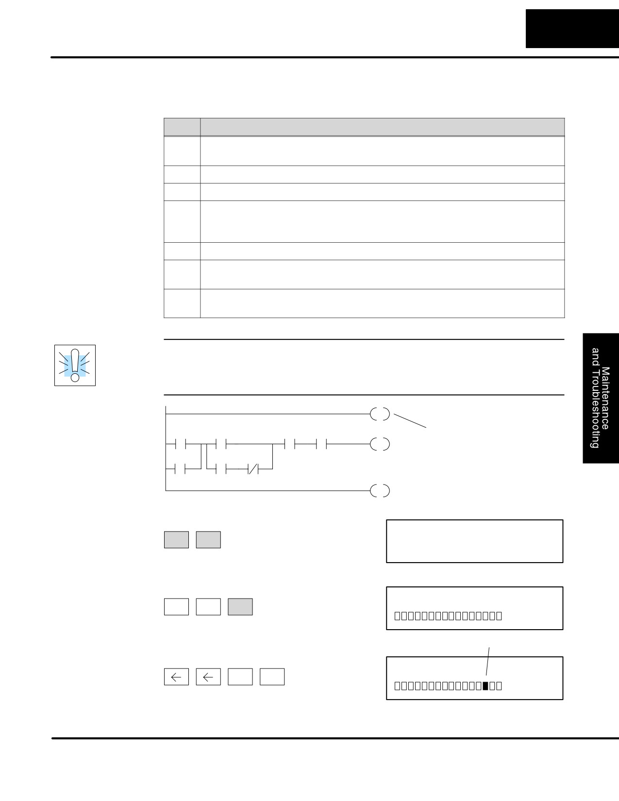
Output points can be set on or off in the DL105 series CPUs. If you want to do an I/O
Points
check out independent of the application program, follow the procedure below:
Step
Action
Use a handheld programmer or DirectSOFT32 to communicate online
1
to the PLC.
2
Change to Program Mode.
3
Go to address 0.
Insert an “END” statement at address 0. (This will cause program
4
execution to occur only at address 0 and prevent the application pro-
gram from turning the I/O points on or off).
5
Change to Run Mode.
Use the programming device to set (turn) on or off the points you wish
6
to test.
When you finish testing I/O points delete the “END” statement at
7
address 0.
WARNING: Depending on your application, forcing I/O points may cause
unpredictable machine operation that can result in a risk of personal injury or
equipment damage. Make sure you have taken all appropriate safety precautions
prior to testing any I/O points.
Handheld
END
Programmer
Keystrokes Used
X0
X2
X5
X7
Y2
Insert an END statement
to Test an Output
at the beginning of the
Point
X1
X3
X4
program. This disables
the remainder of the
program.
END
From a clear display, use the following keystrokes
16P STATUS
STAT
ENT
BIT REF
X
Use the PREV or NEXT keys to select the Y data type
A
Y
10
Y
0
NEXT
ENT
0
Y2 is now on
Use arrow keys to select point, then use
ON and OFF to change the status
ON
Y
10
Y
0
SHFT
INS
DL105 PLC User Manual, 2nd Edition, Rev. A
8-10
Maintenance and Troubleshooting
Noise Troubleshooting
Electrical Noise
Noise is one of the most difficult problems to diagnose. Electrical noise can enter a
Problems
system in many different ways and they fall into one of two categories, conducted or
radiated. It may be difficult to determine how the noise is entering the system but the
corrective actions for either of the types of noise problems are similar.
S Conducted noise is when the electrical interference is introduced into
the system by way of a attached wire, panel connection ,etc. It may
enter through an I/O circuit, a power supply connection, the
communication ground connection, or the chassis ground connection.
S Radiated noise is when the electrical interference is introduced into the
system without a direct electrical connection, much in the same manner
as radio waves.
Reducing
While electrical noise cannot be eliminated it can be reduced to a level that will not
Electrical Noise
affect the system.
S Most noise problems result from improper grounding of the system. A
good earth ground can be the single most effective way to correct noise
problems. If a ground is not available, install a ground rod as close to
the system as possible. Ensure all ground wires are single point
grounds and are not daisy chained from one device to another. Ground
metal enclosures around the system. A loose wire can act as a large
antenna, introducing noise into the system. Therefore, tighten all
connections in your system. Loose ground wires are more susceptible to
noise than the other wires in your system. Review Chapter 2 Installation,
Wiring, and Specifications if you have questions regarding how to
ground your system.
S Electrical noise can enter the system through the power source for the
PLC and I/O circuits. Installing an isolation transformer for all AC
sources can correct this problem. DC sources should be well-grounded
good quality supplies.
S Separate input wiring from output wiring. Never run low-voltage I/O
wiring close to high voltage wiring.
DL105 PLC User Manual, 2nd Edition, Rev. A
8-11
Maintenance and Troubleshooting
Machine Startup and Program Troubleshooting
The DL105 Micro PLCs provide several features that can help you debug your
program before and during machine startup. This section discusses the following
topics which can be very helpful.
S Program Syntax Check
S Duplicate Reference Check
S Special Instructions
S Run Time Edits
S Forcing I/O Points
Syntax Check
Even though the Handheld Programmer and DirectSOFT32 provide error checking
during program entry, you may want to check a program that has been modified.
Both programming devices offer a way to check the program syntax. For example,
you can use AUX 21, CHECK PROGRAM to check the program syntax from a
Handheld Programmer, or you can use the PLC Diagnostics menu option within
DirectSOFT32. This check will find a wide variety of programming errors. The
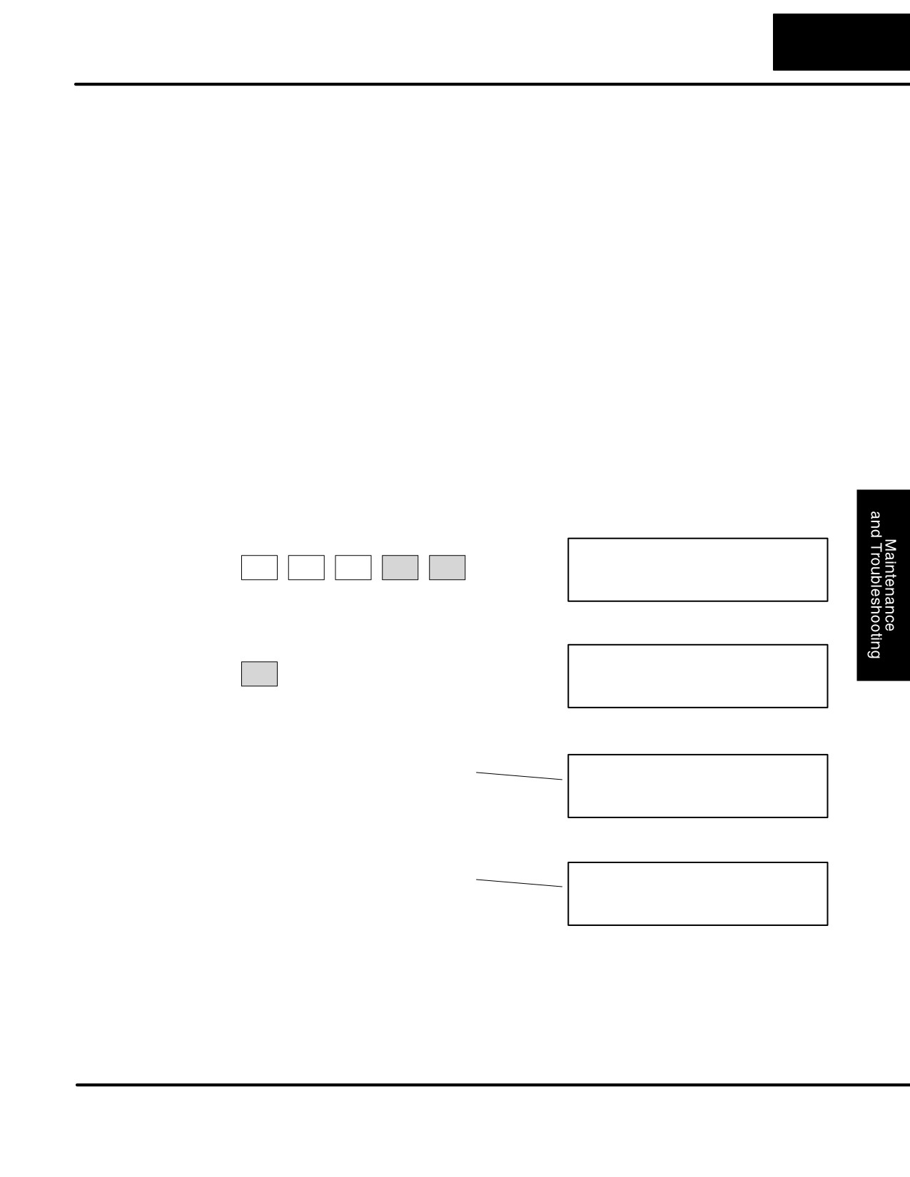
following example shows how to use the syntax check with a Handheld Programmer.
Use AUX 21 to perform syntax check
C
B
AUX 21 CHECK PRO
CLR
AUX
ENT
2
1
1:SYN 2:DUP REF
Select syntax check (default selection)
(You may not get the busy display
BUSY
ENT
if the program is not very long.)
One of two displays will appear
Error Display (example)
$00050 E401
MISSING END
(shows location in question)
Syntax OK display
NO SYNTAX ERROR
?
See the Error Codes Section for a complete listing of programming error codes. If
you get an error, just press CLR and the Handheld will display the instruction where
the error occurred. Correct the problem and continue running the Syntax check until
the NO SYNTAX ERROR message appears.
DL105 PLC User Manual, 2nd Edition, Rev. A
8-12
Maintenance and Troubleshooting
Special
There are several instructions that can be used to help you debug your program
Instructions
during machine startup operations.
S END
S PAUSE
S STOP
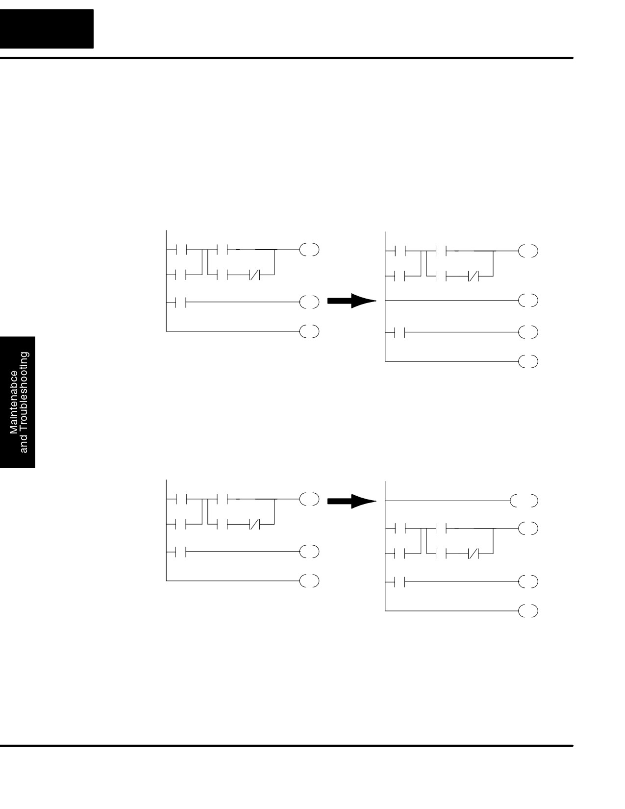
END Instruction: If you need a way to quickly disable part of the program, just insert
an END statement prior to the portion that should be disabled. When the CPU
encounters the END statement, it assumes that is the end of the program. The
following diagram shows an example.
Normal Program
New END disables X10 and Y1
X0
X2
Y0
X0
X2
Y0
X1
X3
X4
X1
X3
X4
X10
Y1
END
X10
Y1
END
END
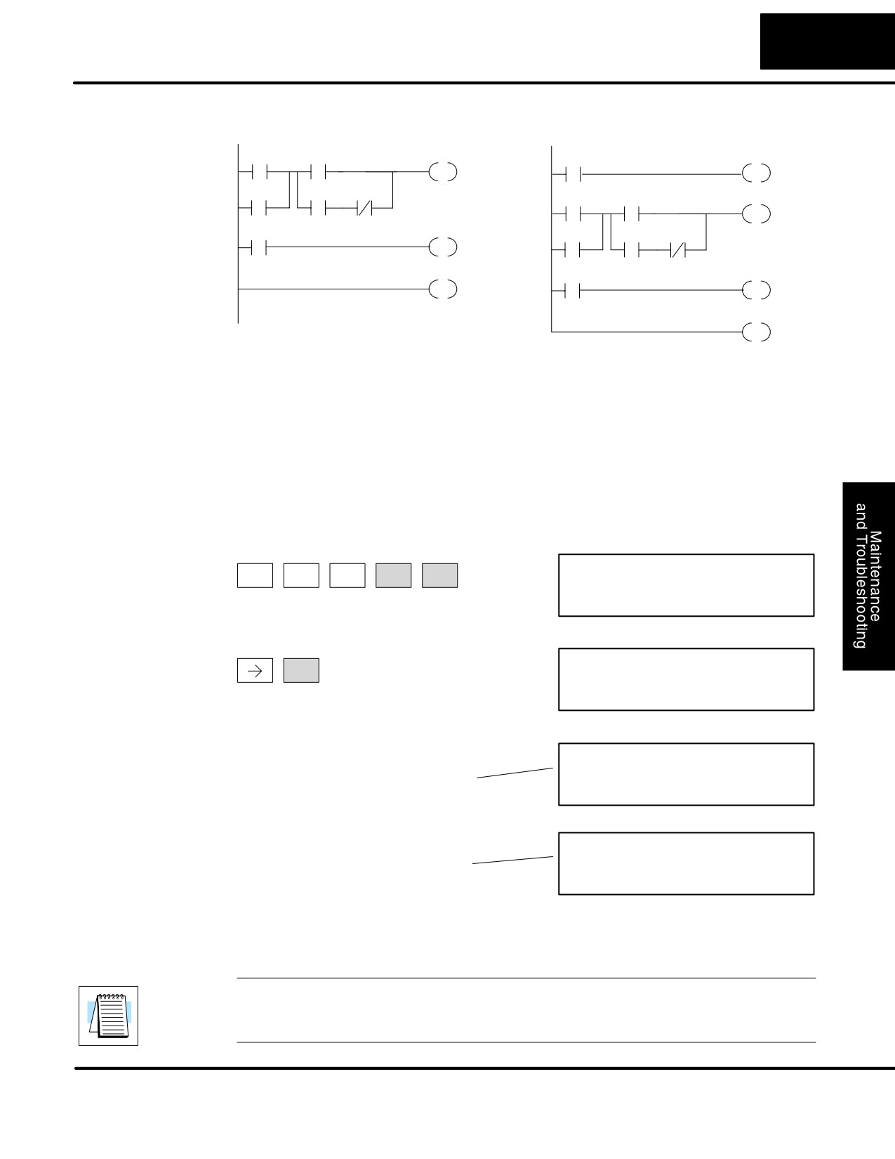
PAUSE Instruction: This instruction provides a quick way to allow the inputs (or
other logic) to operate while disabling selected outputs. The output image register is
still updated, but the output circuits are not. For example, you could make this
conditional by adding an input contact or CR to control the instruction with a switch or
a programming device. Or, you could just add the instruction without any conditions
so the selected outputs would be disabled at all times.
Normal Program
PAUSE disables Y0 and Y1
X0
X2
Y0
Y0 - Y1
PAUSE
X1
X3
X4
X0
X2
Y0
X10
Y1
X1
X3
X4
X10
Y1
END
END
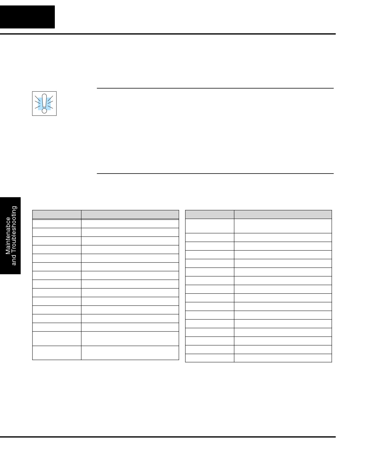
STOP Instruction: Sometimes during machine startup you need a way to quickly
turn off all the outputs and return to Program Mode. You can use the STOP
instruction. When this instruction is executed the CPU automatically exits Run Mode
and enters Program Mode. Remember, all outputs are turned off during Program
Mode. The following diagram shows an example of a condition that returns the CPU
to Program Mode.
DL105 PLC User Manual, 2nd Edition, Rev. A
8-13
Maintenance and Troubleshooting
Normal Program
STOP puts CPU in Program Mode
X0
X2
Y0
X10
STOP
X1
X3
X4
X0
X2
Y0
X5
Y1
X1
X3
X4
X5
Y1
END
END
In the example shown above, you could trigger X10 which would execute the STOP
instruction. The CPU would enter Program Mode and all outputs would be turned off.
Duplicate
You can also check for multiple uses of the same output coil. Both programming
Reference Check
devices offer a way to check for this condition.. For example, you can AUX 21,
CHECK PROGRAM to check for duplicate references from a Handheld
Programmer, or you can use the PLC Diagnostics menu option within
DirectSOFT32. The following example shows how to perform the duplicate
reference check with a Handheld Programmer.
Use AUX 21 to perform syntax check
C
B
CLR
AUX
ENT
AUX 21 CHECK PRO
2
1
1:SYN 2:DUP REF
Select duplicate reference check
(You may not get the busy
ENT
BUSY
display if the program is not
very long.)
One of two displays will appear
$00024 E471
Error Display (example)
DUP COIL REF
(shows location in question)
NO DUP REFS
Syntax OK display
?
If you get an error, just press CLR and the Handheld will display the instruction where
the error occurred. Correct the problem and continue running the Duplicate
Reference check until no duplicate references are found.
NOTE: You can use the same coil in more than one location, especially in programs
containing Stage instructions and
/ or OROUT instructions. The Duplicate
Reference check will find occurrences, even though they are acceptable.
DL105 PLC User Manual, 2nd Edition, Rev. A
8-14
Maintenance and Troubleshooting
Run Time Edits
The DL105 Micro PLC allows you to make changes to the application program
during Run Mode. These edits are not
“bumpless.” Instead, CPU scan is
momentarily interrupted (and the outputs are maintained in their current state) until
the program change is complete. This means if the output is off, it will remain off until
the program change is complete. If the output is on, it will remain on.
WARNING: Only authorized personnel fully familiar with all aspects of the
application should make changes to the program. Changes during Run Mode
become effective immediately. Make sure you thoroughly consider the impact of any
changes to minimize the risk of personal injury or damage to equipment. There are
some important operational changes during Run Time Edits.
1. If there is a syntax error in the new instruction, the CPU will not enter the Run
Mode.
2. If you delete an output coil reference and the output was on at the time, the output
will remain on until it is forced off with a programming device.
3. Input point changes are not acknowledged during Run Time Edits. So, if you’re
using a high-speed operation and a critical input comes on, the CPU may not see
the change.
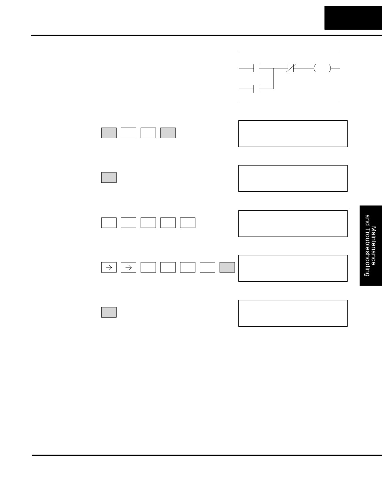
Not all instructions can be edited during a Run Time Edit session. The following list
shows the instructions that can be edited.
Mnemonic
Description
Mnemonic
Description
TMR
Timer
OR, ORN
Or greater than or equal
Or less than
TMRF
Fast timer
LD
Load data (constant)
TMRA
Accumulating timer
LDD
Load data double (constant)
TMRAF
Accumulating fast timer
ADDD
Add data double (constant)
CNT
Counter
SUBD
Subtract data double (constant)
UDC
Up / Down counter
MUL
Multiply (constant)
SGCNT
Stage counter
DIV
Divide (constant)
STR, STRN
Store, Store not
CMPD
Compare accumulator (constant)
AND, ANDN
And, And not
ANDD
And accumulator (constant)
OR, ORN
Or, Or not
ORD
Or accumulator (constant)
STRE, STRNE
Store equal, Store not equal
XORD
Exclusive or accumulator (constant)
ANDE, ANDNE
And equal, And not equal
LDF
Load discrete points to accumulator
ORE, ORNE
Or equal, Or not equal
OUTF
Output accumulator to discrete points
STR, STRN
Store greater than or equal
Store less than
SHFR
Shift accumulator right
AND, ANDN
And greater than or equal
SHFL
Shift accumulator left
And less than
NCON
Numeric constant
DL105 PLC User Manual, 2nd Edition, Rev. A
8-15
Maintenance and Troubleshooting
We’ll use the program logic shown to de-
scribe how this process works. In the ex-
X0
X1
Y0
OUT
ample, we’ll change X0 to C10. Note, the
example assumes you have already
C0
placed the CPU in Run Mode.
Use the MODE key to select Run Time Edits
*MODE CHANGE*
MODE
NEXT
NEXT
ENT
RUN TIME EDIT?
Press ENT to confirm the Run Time Edits
*MODE CHANGE*
(Note, the RUN LED on the D2-HPP
ENT
Handheld starts flashing to indicate
RUNTIME EDITS
Run Time Edits are enabled.)
Find the instruction you want to change (X0)
X
A
FD REF
SHFT
SHFT
SET
0
FIND
$00000 STR X0
Press the arrow key to move to the X. Then enter the new contact (C10).
C
B
A
RUNTIME EDIT?
SHFT
ENT
2
1
0
STR C10
Press ENT to confirm the change
ENT
(Note, once you press ENT, the next
address is displayed.
OR C0
DL105 PLC User Manual, 2nd Edition, Rev. A
8-16
Maintenance and Troubleshooting
Forcing I/O Points
There are many times, especially during machine startup and troubleshooting, that
you need the capability to force an I/O point to be either on or off. Before you use a
programming device to force any data type it is important you understand how the
DL105 CPUs process the forcing requests.
WARNING: Only authorized personnel fully familiar with the application should
make program changes. Do thoroughly consider the impact of any changes to
minimize the risk of personal injury or damage to equipment.
Bit Forcing — Bit forcing temporarily changes the status of a discrete bit. For
example, you may want to force an input on even though the program has turned it
off. This allows you to change the point status stored in the image register. The
forced value will be valid until the CPU writes to the image register location during the
next scan. This is useful you just need to force a bit on to trigger another event.
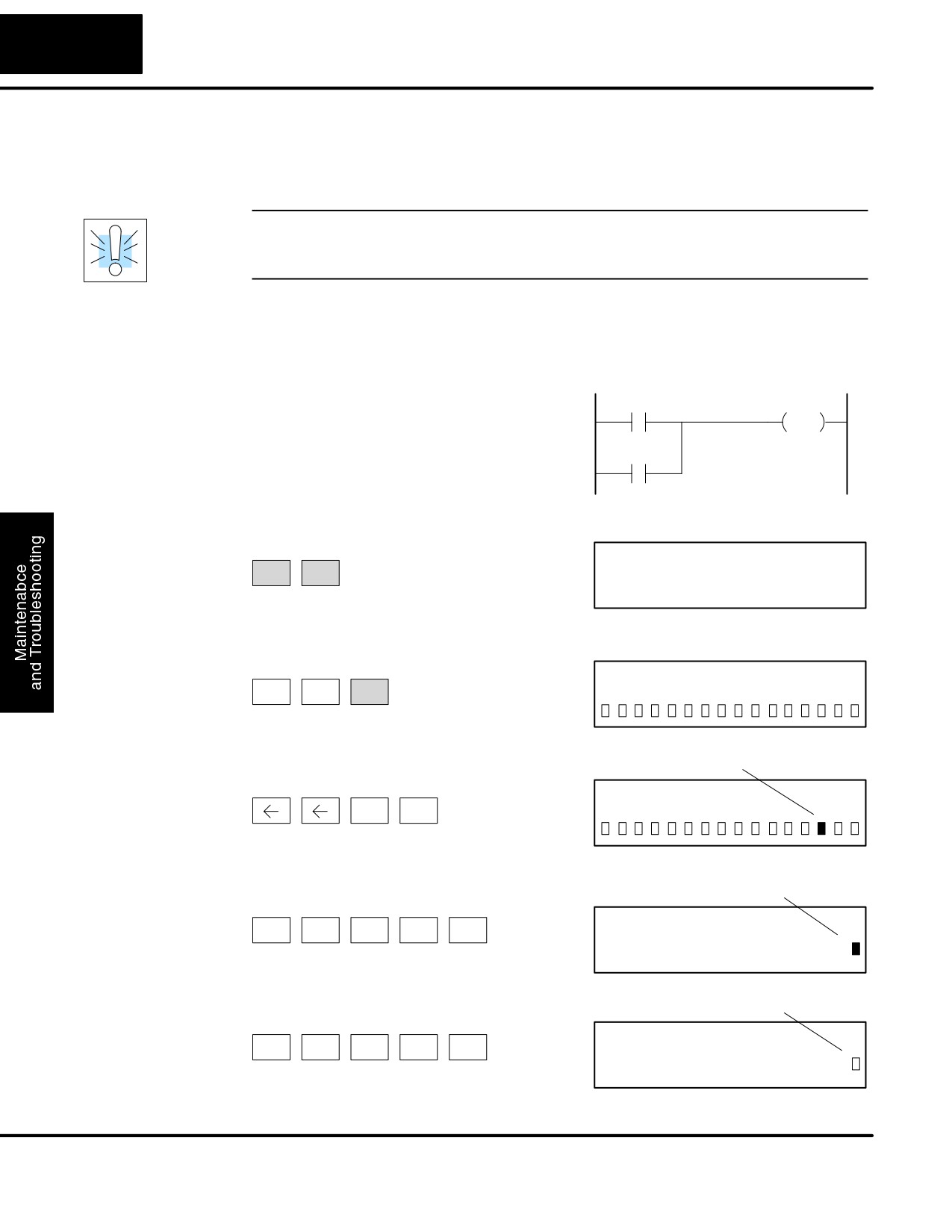
The following diagrams show a brief
X0
Y0
example of how you could use the
OUT
D2-HPP Handheld Programmer to force
an I/O point. The example assumes you
C0
have already placed the CPU into Run
Mode.
From a clear display, use the following keystrokes
16P STATUS
STAT
ENT
BIT REF
X
Use the PREV or NEXT keys to select the Y data type. (Once the Y
appears, press 0 to start at Y0.)
A
Y
1
0
Y
0
NEXT
ENT
0
Use arrow keys to select point, then use
Y2 is now on
ON and OFF to change the status
ON
Y
1
0
Y
0
SHFT
INS
Bit Forcing with
From a blank display, use the following
Solid fill indicates point is on.
Direct Access
keystrokes to force Y7 ON
Y
H
ON
SHFT
SHFT
BIT FORCE
MLS
7
INS
Y7
From a blank display, use the following
No fill indicates point is off.
keystrokes to force Y7 OFF
Y
H
OFF
SHFT
SHFT
BIT FORCE
MLS
7
DEL
Y7
DL105 PLC User Manual, 2nd Edition, Rev. A
A
Auxiliary Functions
In This Appendix
Ċ Introduction
Ċ AUX 2* Ċ RLL Operations
Ċ AUX 3* Ċ VĆmemory Operations
Ċ AUX 4* Ċ I/O Configuration
Ċ AUX 5* Ċ CPU Configuration
Ċ AUX 6* Ċ Handheld Programmer Configuration
Ċ AUX 7* Ċ EEPROM Operations
Ċ AUX 8* Ċ Password Operations
A-2
Auxiliary Functions
Introduction
Purpose of
Many CPU setup tasks involve the use of Auxiliary (AUX) Functions. The AUX
Functions perform many different operations, including clearing ladder memory,
Auxiliary Functions
displaying the scan time, and copying programs to EEPROM in the handheld
programmer. They are divided into categories that affect different system resources.
You can access the AUX Functions from DirectSOFT32 or from the D2-HPP
Handheld Programmer. The manuals for those products provide step-by-step
procedures for accessing the AUX Functions. Some of these AUX Functions are
designed specifically for the Handheld Programmer setup, so they will not be
needed (or available) with the DirectSOFT32 package. Even though this Appendix
provides many examples of how the AUX functions operate, you should supplement
this information with the documentation for your choice of programming device.
Note, the Handheld Programmer may have additional AUX functions that are not
supported with the DL105 PLCs.
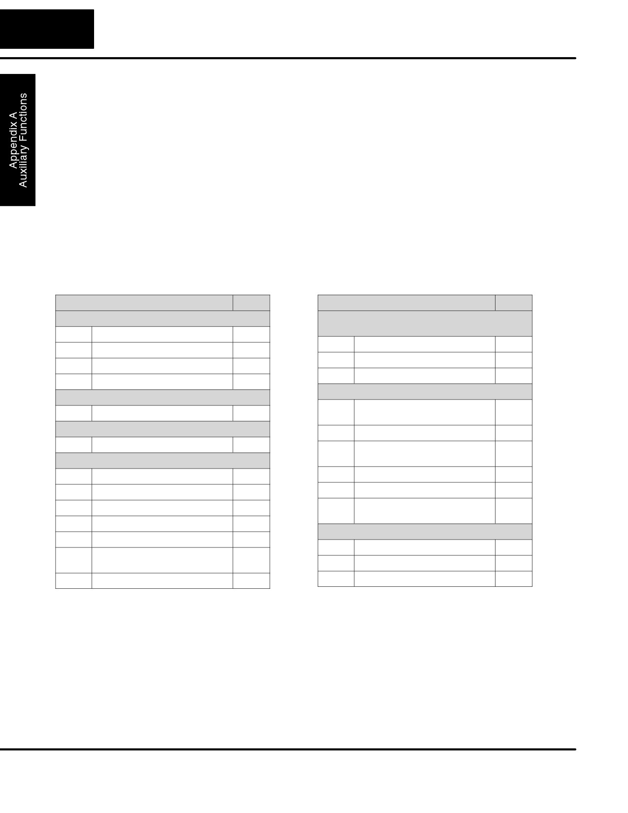
AUX Function and Description
DL105
AUX Function and Description
DL105
AUX 2* — RLL Operations
AUX 6* — Handheld Programmer Configura-
tion
21
Check Program
m
61
Show Revision Numbers
m
22
Change Reference
m
62
Beeper On / Off
HP
23
Clear Ladder Range
m
65
Run Self Diagnostics
HP
24
Clear All Ladders
m
AUX 7* — EEPROM Operations
AUX 3* — V-Memory Operations
71
Copy CPU memory to
HP
31
Clear V Memory
m
HPP EEPROM
AUX 4* — I/O Configuration
72
Write HPP EEPROM to CPU
HP
41
Show I/O Configuration
m
73
Compare CPU to
HP
AUX 5* — CPU Configuration
HPP EEPROM
51
Modify Program Name
m
74
Blank Check (HPP EEPROM)
HP
53
Display Scan Time
m
75
Erase HPP EEPROM
HP
54
Initialize Scratchpad
m
76
Show EEPROM Type
HP
(CPU and HPP)
55
Set Watchdog Timer
m
AUX 8* — Password Operations
57
Set Retentive Ranges
m
81
Modify Password
m
58
Test Operations / Pause Over-
m
ride
82
Unlock CPU
m
5B
HSIO Interface Configuration
m
83
Lock CPU
m
m — supported
HP — Handheld Programmer function
DL105 PLC User Manual, 2nd Edition, Rev. A
A-3
Auxilliary Functions
Accessing AUX
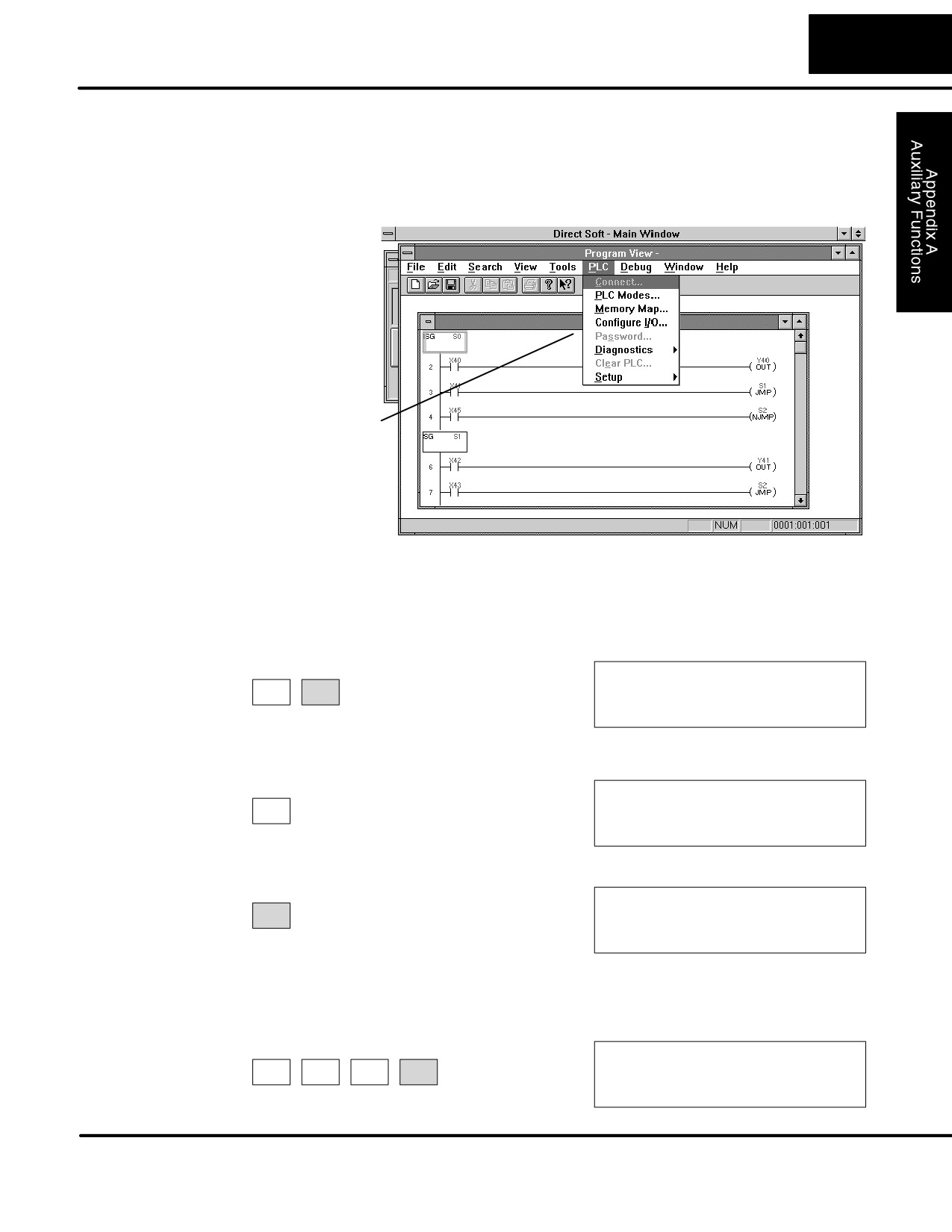
DirectSOFT32 provides various menu options during both online and offline
Functions via
programming. Some of the AUX functions are only available during online
DirectSOFT32
programming, some only during offline programming, and some during both online
and offline programming. The following diagram shows and example of the PLC
operations menu available within DirectSOFT32.
Menu Options
Accessing AUX
You can also access the AUX functions by using a Handheld Programmer. Plus,
Functions via the
remember some of the AUX functions are only available from the Handheld.
Handheld
Sometimes the AUX name or description cannot fit on one display. If you want to see
Programmer
the complete description, just press the arrow keys to scroll left and right. Also,
depending on the current display, you may have to press CLR more than once.
AUX FUNCTION SELECTION
CLR
AUX
AUX 2* RLL OPERATIONS
Use NXT or PREV to cycle through the menus
AUX FUNCTION SELECTION
NEXT
AUX 3* V OPERATIONS
Press ENT to select sub-menus
ENT
AUX 3* V OPERATIONS
AUX 31 CLR V MEMORY
You can also enter the exact AUX number to go straight to the sub-menu.
Enter the AUX number directly
D
B
AUX 3* V OPERATIONS
CLR
AUX
3
1
AUX 31 CLR V MEMORY
DL105 PLC User Manual, 2nd Edition, Rev. A
A-4
Auxiliary Functions
AUX 2* — RLL Operations
RLL Operations auxiliary functions allow you to perform various operations on the
ladder program.
AUX 21
Both the Handheld and DirectSOFT32 automatically check for errors during
Check Program
program entry. However, there may be occasions when you want to check a program
that has already been in the CPU. Two types of checks are available:
S Syntax
S Duplicate References
The Syntax check will find a wide variety of programming errors, such as missing
END statements. If you perform this check and get an error, see Appendix B for a
complete listing of programming error codes. Correct the problem and then continue
running the Syntax check until the message “NO SYNTAX ERROR appears.
Use the Duplicate Reference check to verify you have not used the same output coil
reference more than once. Note, this AUX function will also find the same outputs
even if they have been used with the OROUT instruction, which is perfectly
acceptable.
This AUX function is available on the PLC Diagnostics sub-menu from within
DirectSOFT32.
AUX 22
There will probably be times when you need to change an I/O address reference or
Change Reference
control relay reference. AUX 22 allows you to quickly and easily change all
occurrences, (within an address range), of a specific instruction. For example, you
can replace every instance of X5 with X10.
AUX 23
There have been many times when we’ve taken existing programs and added or
Clear Ladder
removed certain portions to solve new application problems. By using AUX 23 you
Range
can select and delete a portion of the program. DirectSOFT32 does not have a
menu option for this AUX function, but you can just select the appropriate portion of
the program and cut it with the editing tools.
AUX 24
AUX 24 clears the entire program from CPU memory. Before you enter a new
Clear Ladders
program, you should always clear ladder memory. This AUX function is available on
the PLC/Clear PLC sub-menu within DirectSOFT32.
AUX 3* — V-memory Operations
AUX 31
AUX 31 clears all the information from the V-memory locations available for general
Clear V Memory
use. This AUX function is available on the PLC/Clear PLC sub-menu within
DirectSOFT32.
AUX 4* — I/O Configuration
AUX 41
This AUX function allows you to display the current I/O configuration on the DL105.
Show I/O
Both the Handheld Programmer and DirectSOFT32 will show the I/O configuration
Configuration
is fixed at F1-130:10 DI / 8 DO.
DL105 PLC User Manual, 2nd Edition, Rev. A
A-5
Auxilliary Functions
AUX 5* — CPU Configuration
The following auxiliary AUX functions allow you to setup, view, or change the CPU
configuration.
AUX 51
DL105 PLCs can use a program name for the CPU program or a program stored on
Modify Program
EEPROM in the Handheld Programmer. (Note, you cannot have multiple programs
Name
stored on the EEPROM.) The program name can be up to eight characters in length
and can use any of the available characters (A-Z, 0-9). AUX 51 allows you to enter a
program name. You can also perform this operation from within DirectSOFT32 by
using the PLC/Setup sub-menu. Once you’ve entered a program name, you can
only clear the name by using AUX 54 to reset the system memory. Make sure you
understand the possible effects of AUX 54 before you use it!
AUX 53
AUX 53 displays the current, minimum, and maximum scan times. The minimum
Display Scan Time
and maximum times are the ones that have occurred since the last Program Mode to
Run Mode transition. You can also perform this operation from within DirectSOFT32
by using the PLC/Diagnostics sub-menu.
AUX 54
The CPU maintains system parameters in a memory area often referred to as the
Initialize
“scratchpad”. In some cases, you may make changes to the system setup that will be
Scratchpad
stored in system memory. For example, if you specify a range of Control Relays
(CRs) as retentive, these changes are stored.
NOTE: You may never have to use this feature unless you have made changes that
affect system memory. Usually, you’ll only need to initialize the system memory if you
are changing programs and the old program required a special system setup. You
can usually change from program to program without ever initializing system
memory.
AUX 54 resets the system memory to the default values. You can also perform this
operation from within DirectSOFT32 by using the PLC/Setup sub-menu.
AUX 55
DL105 PLCs have a “watchdog” timer that is used to monitor the scan time. The
Set Watchdog
default value set from the factory is 200 ms. If the scan time exceeds the watchdog
Timer
time limit, the CPU automatically leaves RUN mode and enters PGM mode. The
Handheld displays the following message E003 S/W TIMEOUT when the scan
overrun occurs.
Use AUX 55 to increase or decrease the watchdog timer value. You can also perform
this operation from within DirectSOFT32 by using the PLC/Setup sub-menu.
AUX 57
DL105 CPUs provide certain ranges of retentive memory by default. Some of the
Set Retentive
retentive memory locations are backed up by a super-capacitor, and others are in
Ranges
non-volatile EEPROM. The EEPROM memory locations are V4000 to 4177, and
V7630 to V7647. The default ranges are suitable for many applications, but you can
change them if your application requires additional retentive ranges or no retentive
ranges at all (see Appendix E).
DL105 PLC User Manual, 2nd Edition, Rev. A
A-6
Auxiliary Functions
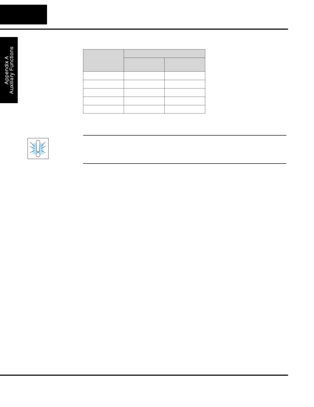
The default settings are:
DL105
Memory Area
Default Range
Available
Range
Control Relays
C300 - C377
C0 - C377
V Memory
V2000 - V7777
V0 - V7777
Timers
None by default
T0 - T77
Counters
CT0 - CT77
CT0 - CT77
Stages
None by default
S0 - S377
Use AUX 57 to change the retentive ranges. You can also perform this operation
from within DirectSOFT32 by using the PLC/Setup sub-menu.
WARNING: The DL105 CPUs do not have battery-backed RAM. The
super-capacitor will retain the values in the event of a power loss, but only up to 3
weeks. (The retention time may be as short as 4 1/2 days in 60 degree C operating
temperature.)
AUX 58
AUX 58 is used to override the output disable function of the Pause instruction. Use
Test Operations
AUX 58 to program a single output or a range of outputs which will operate normally
even when those points are within the scope of the pause instruction.
AUX 5B
AUX 5B is used with the High-Speed I/O (HSIO) function to select the configuration.
Counter Interface
You can choose the type of counter, set the counter parameters, etc. See Chapter 3
Configuration
for a complete description of how to select the various counter features.
AUX 6* — Handheld Programmer Configuration
The following auxiliary functions allow you to setup, view, or change the Handheld
Programmer configuration.
AUX 61
As with most industrial control products, there are cases when additional features
Show Revision
and enhancements are made. Sometimes these new features only work with certain
Numbers
releases of firmware. By using AUX 61 you can quickly view the CPU and Handheld
Programmer firmware revision numbers. This information (for the CPU) is also
available from within DirectSOFT32 from the PLC/Diagnostics sub-menu.
AUX 62
The Handheld has a beeper that provides confirmation of keystrokes. You can use
Beeper On / Off
Auxiliary (AUX) Function 62 to turn off the beeper.
AUX 65
If you think the Handheld Programmer is not operating correctly, you can use AUX 65
Run Self
to run a self diagnostics program. You can check the following items.
Diagnostics
S Keypad
S Display
S LEDs and Backlight
S Handheld Programmer EEPROM check
DL105 PLC User Manual, 2nd Edition, Rev. A

A-7
Auxilliary Functions
AUX 7* — EEPROM Operations
The following auxiliary functions allow you to move the ladder program from one
area to another and perform other program maintenance tasks.
Transferrable
Many of these AUX functions allow you to copy different areas of memory to and
Memory Areas
from the CPU and handheld programmer. The following table shows the areas that
may be mentioned.
Option and Memory Type
DL105 Default Range
1:PGM — Program
$00000 - $02047
2:V — V memory
$00000 - $03777
3:SYS — System
Non-selectable copies
system parameters
4:etc (All)— Program, Sys-
Non-selectable
tem and non-volatile V-
memory only
AUX 71
AUX 71 copies information from the CPU memory to an EEPROM installed in the
CPU to HPP
Handheld Programmer.You can copy different portions of EEPROM (HP) memory to
EEPROM
the CPU memory as shown in the previous table.
AUX 72
AUX 72 copies information from the EEPROM installed in the Handheld
HPP EEPROM
Programmer to CPU memory in the DL105. You can copy different portions of
to CPU
EEPROM (HP) memory to the CPU memory as shown in the previous table.
AUX 73
AUX 73 compares the program in the Handheld programmer (EEPROM) with the
Compare HPP
CPU program. You can compare different types of information as shown previously.
EEPROM to CPU
AUX 74
AUX 74 allows you to check the EEPROM in the handheld programmer to make sure
HPP EEPROM
it is blank. It’s a good idea to use this function anytime you start to copy an entire
Blank Check
program to an EEPROM in the handheld programmer.
AUX 75
AUX 75 allows you to clear all data in the EEPROM in the handheld programmer.
Erase HPP
You should use this AUX function before you copy a program from the CPU.
EEPROM
AUX 76
You can use AUX 76 to quickly determine what size EEPROM is installed in the
Show EEPROM
Handheld Programmer.
Type
DL105 PLC User Manual, 2nd Edition, Rev. A
A-8
Auxiliary Functions
AUX 8* — Password Operations
There are several AUX functions available that you can use to modify or enable the
CPU password. You can use these features during on-line communications with the
CPU, or, you can also use them with an EEPROM installed in the Handheld
Programmer during off-line operation. This will allow you to develop a program in the
Handheld Programmer and include password protection.
S AUX 81 — Modify Password
S AUX 82 — Unlock CPU
S AUX 83 — Lock CPU
AUX 81
You can use AUX 81 to provide an extra measure of protection by entering a
Modify Password
password that prevents unauthorized machine operations. The password must be
an eight-character numeric (0-9) code. Once you’ve entered a password, you can
remove it by entering all zeros (00000000). (This is the default from the factory.)
Once you’ve entered a password, you can lock the CPU against access. There are
two ways to lock the CPU with the Handheld Programmer.
S The CPU is always locked after a power cycle (if a password is present).
S You can use AUX 82 and AUX 83 to lock and unlock the CPU.
You can also enter or modify a password from within DirectSOFT32 by using the
PLC/Password sub-menu. This feature works slightly differently in DirectSOFT32.
Once you’ve entered a password, the CPU is automatically locked when you exit the
software package. It will also be locked if the CPU is power cycled.
WARNING: Make sure you remember the password before you lock the CPU. Once
the CPU is locked you cannot view, change, or erase the password. If you do not
remember the password, you have to return the CPU to the factory for password
removal.
NOTE: The DL105 CPUs support multi-level password protection of the ladder
program. This allows password protection while not locking the communication port
to an operator interface. The multi-level password can be invoked by creating a
password with an upper case “A” followed by seven numeric characters (e.g.
A1234567).
AUX 82
AUX 82 can be used to unlock a CPU that has been password protected.
Unlock CPU
DirectSOFT32 will automatically ask you to enter the password if you attempt to
communicate with a CPU that contains a password.
AUX 83
AUX 83 can be used to lock a CPU that contains a password. Once the CPU is
Lock CPU
locked, you will have to enter a password to gain access. Remember, this is not
necessary with DirectSOFT32 since the CPU is automatically locked whenever you
exit the software package.
DL105 PLC User Manual, 2nd Edition, Rev. A
B
DL105 Error Codes
In This Appendix
Ċ Error Code Table

B-2
DL105 Error Codes
DL105 Error Code
Description
E003
If the program scan time exceeds the time allotted to the watchdog timer, this
SOFTWARE
error will occur. SP51 will be on and the error code will be stored in V7755. To
TIME-OUT
correct this problem use AUX 55 to extend the time allotted to the watchdog
timer.
E004
The CPU attempted to execute an instruction code, but the RAM contents
INVALID
had a parity error. Performing a program download to the CPU in an
INSTRUCTION
electrically noisy environment can corrupt a program’s contents. Clear the
CPU program memory, and download the program again.
E099
If the compiled program length exceeds the amount of available CPU RAM
PROGRAM
this error will occur. SP52 will be on and the error code will be stored in
MEMORY
V7755. Reduce the size of the application program.
EXCEEDED
E151
A parity error has occurred in the application program. SP44 will be on and
BAD COMMAND
the error code will be stored in V7755 .This problem may possibly be due to
electrical noise. Clear the memory and download the program again. Correct
any grounding problems. If the error returns replace the Micro PLC.
E155
A checksum error has occurred in the system RAM. SP44 will be on and the
RAM FAILURE
error code will be stored in V7755. This problem may possibly be due to a low
battery, electrical noise or a CPU RAM failure. Clear the memory and
download the program again. Correct any grounding problems. If the error
returns replace the CPU.
E210
A short duration power drop-out occurred on the main power line supplying
POWER FAULT
power to the base.
DL105 PLC User Manual, 2nd Edition, Rev. A

B-3
DL105 Error Codes
DL105 Error Code
Description
E312
A data error was encountered during communications with the CPU. Clear
HP COMM
the error and retry the request. If the error continues check the cabling
ERROR 2
between the two devices, replace the handheld programmer, then if
necessary replace the CPU. The error code will be stored in V7756.
E313
An address error was encountered during communications with the CPU.
HP COMM
Clear the error and retry the request. If the error continues check the cabling
ERROR 3
between the two devices, replace the handheld programmer, then if
necessary replace the CPU. The error code will be stored in V7756.
E316
A mode error was encountered during communications with the CPU. Clear
HP COMM
the error and retry the request. If the error continues replace the handheld
ERROR 6
programmer, then if necessary replace the CPU. The error code will be stored
in V7756.
E320
The CPU did not respond to the handheld programmer communication
HP COMM
request. Check to insure cabling is correct and not defective. Power cycle the
TIME-OUT
system if the error continues replace the CPU first and then the handheld
programmer if necessary.
E321
A data error was encountered during communication with the CPU. Check to
COMM ERROR
insure cabling is correct and not defective. Power cycle the system and if the
error continues replace the CPU first and then the handheld programmer if
necessary.
E4**
A syntax error exists in the application program. The most common is a
NO PROGRAM
missing END statement. Run AUX21 to determine which one of the E4**
series of errors is being flagged. SP52 will be on and the error code will be
stored in V7755.
E401
All application programs must terminate with an END statement. Enter the
MISSING END
END statement in appropriate location in your program. SP52 will be on and
STATEMENT
the error code will be stored in V7755.
E402
A MOVMC or LDLBL instruction was used without the appropriate label.
MISSING LBL
Refer to the Chapter 5 for details on these instructions. SP52 will be on and
the error code will be stored in V7755.
E406
An interrupt routine in the program does not end with the IRT instruction.
MISSING IRT
SP52 will be on and the error code will be stored in V7755.
E421
Two or more SG or ISG labels exist in the application program with the same
DUPLICATE STAGE
number. A unique number must be allowed for each Stage and Initial Stage.
REFERENCE
SP52 will be on and the error code will be stored in V7755.
E422
Two or more LBL instructions exist in the application program with the same
DUPLICATE LBL
number. A unique number must be allowed for each and label. SP52 will be
REFERENCE
on and the error code will be stored in V7755.
E431
An ISG or SG instruction must not be placed after the end statement (such as
INVALID ISG/SG
inside a subroutine). SP52 will be on and the error code will be stored in
ADDRESS
V7755.
DL105 PLC User Manual, 2nd Edition, Rev. A

B-4
DL105 Error Codes
DL105 Error Code
Description
E436
An INT must be programmed after the end statement, not in the main body of
INVALID INT
the program. SP52 will be on and the error code will be stored in V7755.
ADDRESS
E438
An IRT must be programmed after the end statement, not in the main body of
INVALID IRT
the program. SP52 will be on and the error code will be stored in V7755.
ADDRESS
E440
Either the DLBL instruction has been programmed in the main program area
INVALID DATA
(not after the END statement), or the DLBL instruction is on a rung containing
ADDRESS
input contact(s).
E441
An ACON or NCON must be programmed after the end statement, not in the
ACON/NCON
main body of the program. SP52 will be on and the error code will be stored
in V7755.
E451
MLS instructions must be numbered in ascending order from top to bottom.
BAD MLS/MLR
E452
An X data type is being used as a coil output.
X AS COIL
E453
A timer or counter contact is being used where the associated timer or
MISSING T/C
counter does not exist.
E454
One of the contacts is missing from a TMRA instruction.
BAD TMRA
E455
One of the contacts is missing from a CNT or UDC instruction.
BAD CNT
E456
One of the contacts is missing from the SR instruction.
BAD SR
E461
More than nine levels of logic have been stored on the stack. Check the use
STACK OVERFLOW
of OR STR and AND STR instructions.
E462
An unmatched number of logic levels have been stored on the stack. Insure
STACK
the number of AND STR and OR STR instructions match the number of STR
UNDERFLOW
instructions.
E463
A STR instruction was not used to begin a rung of ladder logic.
LOGIC ERROR
E464
A rung of ladder logic is not terminated properly.
MISSING CKT
E471
Two or more OUT instructions reference the same I/O point.
DUPLICATE COIL
REFERENCE
E472
Two or more TMR instructions reference the same number.
DUPLICATE TMR
REFERENCE
E473
Two or more CNT instructions reference the same number.
DUPLICATE CNT
REFERENCE
DL105 PLC User Manual, 2nd Edition, Rev. A

B-5
DL105 Error Codes
DL105 Error Code
Description
E501
An invalid keystroke or series of keystrokes was entered into the handheld
BAD ENTRY
programmer.
E502
An invalid or out of range address was entered into the handheld
BAD ADDRESS
programmer.
E503
An invalid command was entered in the handheld programmer.
BAD COMMAND
E504
An invalid value or reference number was entered with an instruction.
BAD REF/VAL
E505
An invalid instruction was entered into the handheld programmer.
INVALID
INSTRUCTION
E506
An invalid operation was attempted by the handheld programmer.
INVALID
OPERATION
E520
An operation which is invalid in the RUN mode was attempted by the
BAD OP-RUN
handheld programmer.
E524
An operation which is invalid in the PROGRAM mode was attempted by the
BAD OP-PGM
handheld programmer.
E526
The handheld programmer is in the OFFLINE mode. To change to the
OFF LINE
ONLINE mode use the MODE the key.
E527
The handheld programmer is in the ON LINE mode. To change to the OFF
ON LINE
LINE mode use the MODE the key.
E528
The operation attempted is not allowed during a Run Time Edit.
CPU MODE
E540
The CPU has been password locked. To unlock the CPU use AUX82 with the
CPU LOCKED
password.
E541
The password used to unlock the CPU with AUX82 was incorrect.
WRONG
PASSWORD
E542
The CPU powered up with an invalid password and reset the password to
PASSWORD RESET
00000000. A password may be re-entered using AUX81.
DL105 PLC User Manual, 2nd Edition, Rev. A

B-6
DL105 Error Codes
DL105 Error Code
Description
E601
Attempted to enter an instruction which required more memory than is
MEMORY FULL
available in the CPU.
E602
A search function was performed and the instruction was not found.
INSTRUCTION
MISSING
E604
A search function was performed and the reference was not found.
REFERENCE
MISSING
E620
An attempt to transfer more data between the CPU and handheld
OUT OF MEMORY
programmer than the receiving device can hold.
E621
An attempt to write to a non-blank EEPROM in the handheld programmer
EEPROM NOT
was made. Erase the EEPROM and then retry the write.
BLANK
E622
A data transfer was attempted with no EEPROM (or possibly a faulty
NO HPP EEPROM
EEPROM) installed in the handheld programmer.
E623
A function was requested with an EEPROM in the handheld programmer
SYSTEM EEPROM
which contains system information only.
E624
A function was requested with an EEPROM in the handheld programmer
V-MEMORY ONLY
which contains V-memory data only.
E625
A function was requested with an EEPROM in the handheld programmer
PROGRAM ONLY
which contains program data only.
E627
An attempt to write to a write-protected or faulty EEPROM in the handheld
BAD WRITE
programmer was made. Check the write protect jumper and replace the
EEPROM if necessary.
E628
The wrong size EEPROM is being used in the handheld programmer. This
EEPROM TYPE
error occurs when the program size is larger than what the HPP can hold.
ERROR
E640
A compare between the EEPROM handheld programmer and the CPU was
COMPARE ERROR
found to be in error.
E650
A system error has occurred in the handheld programmer. Power cycle the
HPP SYSTEM
handheld programmer. If the error returns replace the handheld programmer.
ERROR
E651
A ROM error has occurred in the handheld programmer. Power cycle the
HPP ROM ERROR
handheld programmer. If the error returns replace the handheld programmer.
E652
A RAM error has occurred in the handheld programmer. Power cycle the
HPP RAM ERROR
handheld programmer. If the error returns replace the handheld programmer.
DL105 PLC User Manual, 2nd Edition, Rev. A
C
Instruction
Execution Times
In This Appendix
Ċ Introduction
Ċ Instruction Execution Times
C-2
Instruction Execution Times
Introduction
This appendix contains several tables that provide the instruction execution times
for DL105 Micro PLCs. Many of the execution times depend on the type of data used
with the instruction. Registers may be classified into the following types:
S Data (word) Registers
S Bit Registers
V-Memory Data
Some V-memory locations are considered data registers, such as timer or counter
Registers
current values. Standard user V memory is classified as a V-memory data register.
Note that you can load a bit pattern into these types of registers, even though their
primary use is for data registers. The following locations are data registers:
Data Registers
DL105
Timer Current Values
V0 - V77
Counter Current Values
V1000 - V1077
User Data Words
V2000 - V2377
V4000 - V4177
V-Memory Bit
You may recall that some of the discrete points such as X, Y, C, etc. are automatically
Registers
mapped into V memory (see Appendix E). The following bit registers contain this
data:
Bit Registers
DL105
Input Points (X)
V40400 - V 40407
Output Points (Y)
V40500 - V40507
Control Relays (C)
V40600 - V40617
Timer Status Bits
V41100 - V41103
Counter Status Bits
V41140 - V41143
Stages
V41000 - V41017
Two Data Locations Available
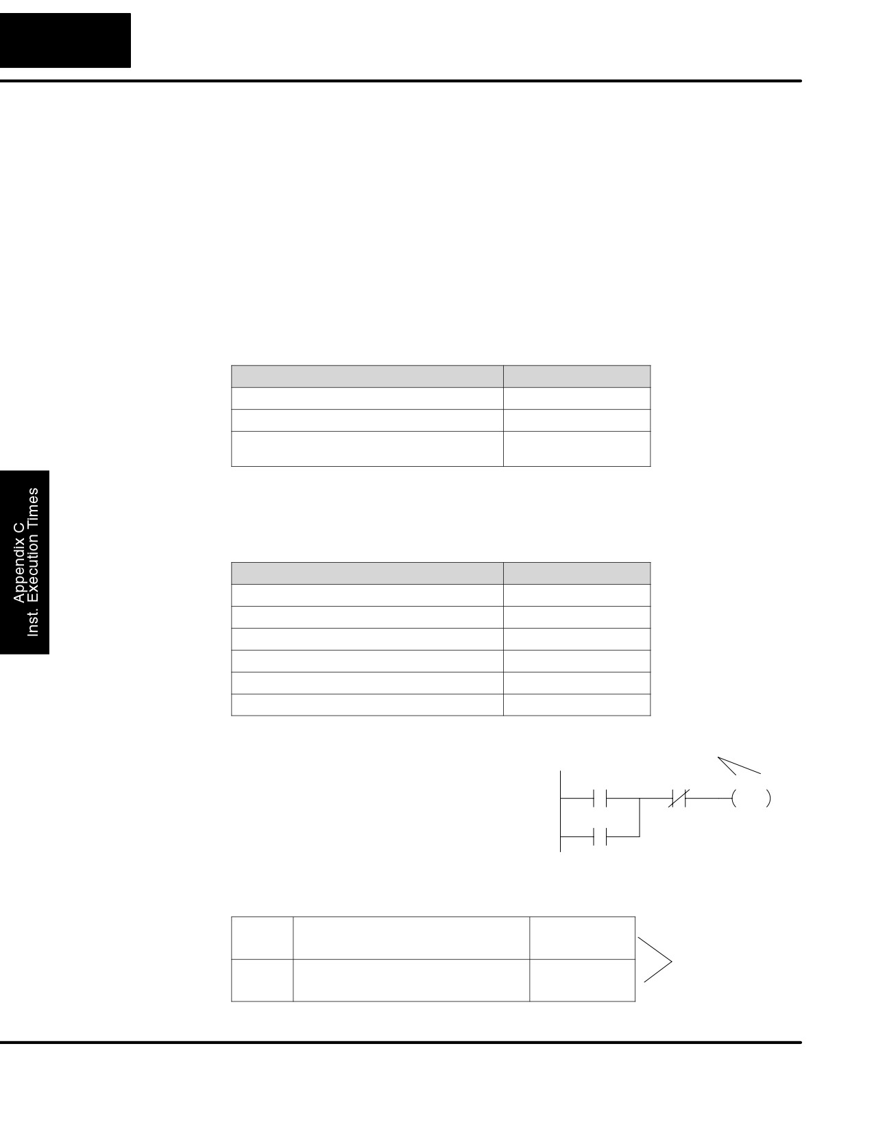
How to Read the
Some instructions can have more than
Tables
one parameter. For example, the SET
X0
X1
Y0 - Y7
instruction shown in the ladder program to
SET
the right can set a single point or a range of
C0
points.
In these cases, execution times that depend on the amount and type of parameters.
The execution time tables list execution times for both situations, as shown below:
SET
1st #:
X, Y, C, S
17.4 ms
Execution depends
2nd #: X, Y, C, S,
(N pt)
12.0ms+5.4msxN
on numbers of
locations and types
RST
1st #:
X, Y, C, S
19.5 ms
of data used
2nd #: X, Y, C, S,
(N pt)
10.5ms+5.2msxN
DL105 PLC User Manual, 2nd Edition, Rev. A
C-3
Instruction Execution Times
Instruction Execution Times
Boolean
DL105
Boolean Instructions
Instructions
Instruction
Legal Data Types
Execute
Not Execute
STR
X, Y, C, T, CT,S, SP
3.3 ms
3.3 ms
STRN
X, Y, C, T, CT,S, SP
3.9 ms
3.9 ms
OR
X, Y, C, T, CT, S, SP
2.7 ms
2.7 ms
ORN
X, Y, C, T, CT,S, SP
3.3 ms
3.3 ms
AND
X, Y, C, T, CT, S, SP
2.1 ms
2.1 ms
ANDN
X, Y, C, T, CT, S, SP
2.7 ms
2.7 ms
ANDSTR
None
1.2 ms
1.2 ms
ORSTR
None
1.2 ms
1.2 ms
OUT
X, Y, C
3.4 ms
3.4 ms
OROUT
X, Y, C
8.6 ms
8.6 ms
PD
X, Y, C
13.5 ms
13.5 ms
SET
1st #:
X, Y, C, S
17.4 ms
6.8 ms
2nd #: X, Y, C, S
(N pt)
12.0ms+5.4msxN
6.8 ms
RST
1st #:
T, CT
31.6 ms
6.8 ms
2nd #: T, CT
(N pt)
17ms+14.6msxN
6.8 ms
PAUSE
1wd: Y
19.0 ms
19.0 ms
2wd: Y (N points)
15ms+4ms x N
15ms+4ms x N
RST
1st #:
X, Y, C, S
17.7 ms
6.8 ms
2nd #: X, Y, C, S
(N pt)
10.5ms+5.2msxN
6.8 ms
Comparative
DL105
Comparative Boolean Instructions
Boolean
Instruction
Legal Data Types
Execute
Not Execute
Instructions
STRE
1st
2nd
V: Data Reg.
V:Data Reg.
77 ms
13.8 ms
V:Bit Reg.
158 ms
13.8 ms
K:Constant
57 ms
13.8 ms
V: Bit Reg.
V:Data Reg.
158 ms
13.8 ms
V:Bit Reg.
240 ms
13.8 ms
K:Constant
139 ms
13.8 ms
STRNE
1st
2nd
V: Data Reg.
V:Data Reg.
77 ms
13.8 ms
V:Bit Reg.
158 ms
13.8 ms
K:Constant
57 ms
13.8 ms
V: Bit Reg.
V:Data Reg.
158 ms
13.8 ms
V:Bit Reg.
240 ms
13.8 ms
K:Constant
139 ms
13.8 ms
DL105 PLC User Manual, 2nd Edition, Rev. A

C-4
Instruction Execution Times
Comparative Boolean (cont.)
DL105
Instruction
Legal Data Types
Execute
Not Execute
ORE
1st
2nd
V: Data Reg.
V:Data Reg.
75 ms
12.0 ms
V:Bit Reg.
158 ms
12.0 ms
K:Constant
55 ms
12.0 ms
V: Bit Reg.
V:Data Reg.
158 ms
12.0 ms
V:Bit Reg.
239 ms
12.0 ms
K:Constant
137 ms
12.0 ms
ORNE
1st
2nd
V: Data Reg.
V:Data Reg.
75 ms
12.0 ms
V:Bit Reg.
158 ms
12.0 ms
K:Constant
55 ms
12.0 ms
V: Bit Reg.
V:Data Reg.
158 ms
12.0 ms
V:Bit Reg.
239 ms
12.0 ms
K:Constant
137 ms
12.0 ms
ANDE
1st
2nd
V: Data Reg.
V:Data Reg.
75 ms
12.0 ms
V:Bit Reg.
158 ms
12.0 ms
K:Constant
55 ms
12.0 ms
V: Bit Reg.
V:Data Reg.
158 ms
12.0 ms
V:Bit Reg.
239 ms
12.0 ms
K:Constant
137 ms
12.0 ms
ANDNE
1st
2nd
V: Data Reg.
V:Data Reg.
75 ms
12.0 ms
V:Bit Reg.
158 ms
12.0 ms
K:Constant
55 ms
12.0 ms
V: Bit Reg.
V:Data Reg.
158 ms
12.0 ms
V:Bit Reg.
239 ms
12.0 ms
K:Constant
137 ms
12.0 ms
STR
1st
2nd
T, CT
V:Data Reg.
78 ms
13.8 ms
V:Bit Reg.
158 ms
13.8 ms
K:Constant
57 ms
13.8 ms
1st
2nd
V: Data Reg.
V:Data Reg.
78 ms
13.8 ms
V:Bit Reg.
159 ms
13.8 ms
K:Constant
57 ms
13.8 ms
V: Bit Reg.
V:Data Reg.
159 ms
13.8 ms
V:Bit Reg.
241 ms
13.8 ms
K:Constant
139 ms
13.8 ms
STRN
1st
2nd
T, CT
V:Data Reg.
78 ms
13.8 ms
V:Bit Reg.
158 ms
13.8 ms
K:Constant
57 ms
13.8 ms
1st
2nd
V: Data Reg.
V:Data Reg.
78 ms
13.8 ms
V:Bit Reg.
159 ms
13.8 ms
K:Constant
57 ms
13.8 ms
V: Bit Reg.
V:Data Reg.
159 ms
13.8 ms
V:Bit Reg.
241 ms
13.8 ms
K:Constant
139 ms
13.8 ms
DL105 PLC User Manual, 2nd Edition, Rev. A

C-5
Instruction Execution Times
Comparative Boolean (cont.)
DL105
Instruction
Legal Data Types
Execute
Not Execute
OR
1st
2nd
T, CT
V:Data Reg.
75 ms
12.0 ms
V:Bit Reg.
158 ms
12.0 ms
K:Constant
55 ms
12.0 ms
1st
2nd
V: Data Reg.
V:Data Reg.
75 ms
12.0 ms
V:Bit Reg.
158 ms
12.0 ms
K:Constant
55 ms
12.0 ms
V: Bit Reg.
V:Data Reg.
158 ms
12.0 ms
V:Bit Reg.
240 ms
12.0 ms
K:Constant
137 ms
12.0 ms
ORN
1st
2nd
T, CT
V:Data Reg.
75 ms
12.0 ms
V:Bit Reg.
158 ms
12.0 ms
K:Constant
55 ms
12.0 ms
1st
2nd
V: Data Reg.
V:Data Reg.
75 ms
12.0 ms
V:Bit Reg.
158 ms
12.0 ms
K:Constant
55 ms
12.0 ms
V: Bit Reg.
V:Data Reg.
158 ms
12.0 ms
V:Bit Reg.
240 ms
12.0 ms
K:Constant
137 ms
12.0 ms
AND
1st
2nd
T, CT
V:Data Reg.
76 ms
12.0 ms
V:Bit Reg.
158 ms
12.0 ms
K:Constant
55 ms
12.0 ms
1st
2nd
V: Data Reg.
V:Data Reg.
75 ms
12.0 ms
V:Bit Reg.
158 ms
12.0 ms
K:Constant
55 ms
12.0 ms
V: Bit Reg.
V:Data Reg.
158 ms
12.0 ms
V:Bit Reg.
240 ms
12.0 ms
K:Constant
137 ms
12.0 ms
ANDN
1st
2nd
T, CT
V:Data Reg.
76 ms
12.0 ms
V:Bit Reg.
158 ms
12.0 ms
K:Constant
55 ms
12.0 ms
1st
2nd
V: Data Reg.
V:Data Reg.
76 ms
12.0 ms
V:Bit Reg.
158 ms
12.0 ms
K:Constant
55 ms
12.0 ms
V: Bit Reg.
V:Data Reg.
158 ms
12.0 ms
V:Bit Reg.
240 ms
12.0 ms
K:Constant
137 ms
12.0 ms
DL105 PLC User Manual, 2nd Edition, Rev. A

C-6
Instruction Execution Times
Immediate
DL105
Immediate Instructions
Instructions
Instruction
Legal Data Types
Execute
Not Execute
STRI
X
27 ms
9.8 ms
STRNI
X
26 ms
8.6 ms
ORI
X
27 ms
9.8 ms
ORNI
X
26 ms
8.6 ms
ANDI
X
25 ms
8.0 ms
ANDNI
X
24 ms
6.8 ms
OROUTI
Y
45 ms
45 ms
SETI
1st #:
Y
25.5 ms
6.8 ms
2nd #: Y
(N pt)
5.5 ms+20 x N
6.8 ms
RSTI
1st #:
Y
25.5 ms
6.8 ms
2nd #: Y
(N pt)
5 ms+20.5 x N
6.8 ms
Timer, Counter,
DL105
Timer, Counter, Shift Register, and
Shift Register,
Drum Instructions
EDRUM
Instruction
Legal Data Types
Execute
Not Execute
Instructions
TMR
1st
2nd
T
V:Data Reg.
75 ms
31 ms
V:Bit Reg.
158 ms
31 ms
K:Constant
66 ms
31 ms
TMRF
1st
2nd
T
V:Data Reg.
75 ms
31 ms
V:Bit Reg.
158 ms
31 ms
K:Constant
66 ms
31 ms
TMRA
1st
2nd
T
V:Data Reg.
94 ms
56 ms
V:Bit Reg.
304 ms
264 ms
K:Constant
95 ms
45 ms
TMRAF
1st
2nd
T
V:Data Reg.
98 ms
54 ms
V:Bit Reg.
304 ms
264 ms
K:Constant
95 ms
49 ms
CNT
1st
2nd
CT
V:Data Reg.
68 ms
61 ms
V:Bit Reg.
148 ms
141 ms
K:Constant
56 ms
45 ms
SGCNT
1st
2nd
CT
V:Data Reg.
57 ms
64 ms
V:Bit Reg.
140 ms
148 ms
K:Constant
46 ms
53 ms
DL105 PLC User Manual, 2nd Edition, Rev. A

C-7
Instruction Execution Times
Timer, Counter, Shift Register, and
DL105
Drum Instructions Cont’d
Instruction
Legal Data Types
Execute
Not Execute
UDC
1st
2nd
CT
V:Data Reg.
103 ms
74 ms
V:Bit Reg.
310 ms
281 ms
K:Constant
102 ms
70 ms
SR
C
(N points to shift)
30 ms+4.6 ms xN
17.2 ms
EDRUM
CT
320 ms
221 ms
Accumulator Data
DL105
Accumulator / Stack Load and
Instructions
Output Data Instructions
Instruction
Legal Data Types
Execute
Not Execute
LD
V:Data Reg.
68 ms
8.4 ms
V:Bit Reg.
149 ms
8.4 ms
K:Constant
62 ms
8.4 ms
P:Indir. (Data)
169 ms
8.4 ms
P:Indir. (Bit)
256 ms
8.4 ms
LDD
V:Data Reg.
72 ms
8.4 ms
V:Bit Reg.
266 ms
8.4 ms
K:Constant
64 ms
8.4 ms
P:Indir. (Data)
172 ms
8.4 ms
P:Indir. (Bit)
373 ms
8.4 ms
LDF
1st
2nd
X, Y, C, S
K:Constant
77 ms+6.2 ms xN
10 ms
T, CT, SP
(N pt)
LDA
O: (Octal constant for address)
58 ms
8.4 ms
OUT
V:Data Reg.
60 ms
8.4 ms
V:Bit Reg.
132 ms
8.4 ms
P:Indir. (Data)
162 ms
8.4 ms
P:Indir. (Bit)
239 ms
8.4 ms
OUTD
V:Data Reg.
68 ms
8.4 ms
V:Bit Reg.
276 ms
8.4 ms
P:Indir. (Data)
196 ms
8.4 ms
P:Indir. (Bit)
384 ms
8.4 ms
OUTF
1st
2nd
X, Y, C
K:Constant
36 ms+7.6 ms xN
8 ms
(N pt)
POP
None
55 ms
7.2 ms
DL105 PLC User Manual, 2nd Edition, Rev. A
C-8
Instruction Execution Times
Logical
DL105
Logical (Accumulator) Instructions
Instructions
Instruction
Legal Data Types
Execute
Not Execute
AND
V:Data Reg.
63 ms
10.4 ms
V:Bit Reg.
261 ms
10.4 ms
ANDD
K:Constant
53 ms
8.4 ms
OR
V:Data Reg.
59 ms
10.4 ms
V:Bit Reg.
257 ms
10.4 ms
ORD
K:Constant
49 ms
8.4 ms
XOR
V:Data Reg.
60 ms
10.4 ms
V:Bit Reg.
257 ms
10.4 ms
XORD
K:Constant
49 ms
8.4 ms
CMP
V:Data Reg.
59 ms
10.4 ms
V:Bit Reg.
259 ms
10.4 ms
CMPD
V:Data Reg.
63 ms
8.4 ms
V:Bit Reg.
257 ms
8.4 ms
K:Constant
54 ms
8.4 ms
Math Instructions
DL105
Math Instructions (Accumulator)
Instruction
Legal Data Types
Execute
Not Execute
ADD
V:Data Reg.
198 ms
10.6 ms
V:Bit Reg.
397 ms
10.6 ms
ADDD
V:Data Reg.
198 ms
8.4 ms
V:Bit Reg.
397 ms
8.4 ms
K:Constant
188 ms
8.4 ms
SUB
V:Data Reg.
200 ms
10.6 ms
V:Bit Reg.
397 ms
10.6 ms
SUBD
V:Data Reg.
198 ms
8.4 ms
V:Bit Reg.
392 ms
8.4 ms
K:Constant
190 ms
8.4 ms
MUL
V:Data Reg.
497 ms
10.6 ms
V:Bit Reg.
483 ms
10.6 ms
K:Constant
487 ms
8.4 ms
DIV
V:Data Reg.
909 ms
10.6 ms
V:Bit Reg.
1108 ms
10.6 ms
K:Constant
899 ms
8.4 ms
INCB
V:Data Reg.
83 ms
10.4 ms
V:Bit Reg.
349 ms
10.4 ms
DECB
V:Data Reg.
82 ms
10.4 ms
V:Bit Reg.
351 ms
10.4 ms
DL105 PLC User Manual, 2nd Edition, Rev. A
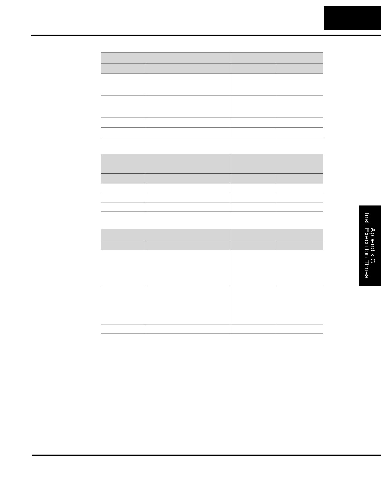
C-9
Instruction Execution Times
Bit Instructions
DL105
Bit Instructions (Accumulator)
Instruction
Legal Data Types
Execute
Not Execute
SHFR
V:Data Reg. (N bits)
44ms+14.6 x N
10.4 ms
V:Bit Reg. (N bits)
243ms+14.6 x N
10.4 ms
K:Constant (N bits)
34ms+14.6 x N
8.4 ms
SHFL
V:Data Reg. (N bits)
44ms+14.6 x N
10.4 ms
V:Bit Reg. (N bits)
243ms+14.6 x N
10.4 ms
K:Constant (N bits)
34ms+14.6 x N
8.4 ms
ENCO
None
62 ms
7.2 ms
DECO
None
34 ms
7.2 ms
Number
DL105
Number Conversion Instructions
Conversion
(Accumulator)
Instructions
Instruction
Legal Data Types
Execute
Not Execute
BIN
None
359 ms
7.2 ms
BCD
None
403 ms
7.2 ms
INV
None
27 ms
5.0 ms
Table Instructions
DL105
Table Instructions
Instruction
Legal Data Types
Execute
Not Execute
MOV
Move V:data reg. to V:data reg.
450ms+17 x N
6.2ms
Move V:bit reg. to V:data reg.
430ms+244 x N
6.2ms
Move V:data reg to V:bit reg.
460ms+215 x N
6.2ms
Move V:bit reg. to V:bit reg.
490ms+448 x N
6.2ms
N= #of words
MOVMC
Move V:Data Reg. to E2
—
—
Move V:Bit Reg. to E2
—
—
Move from E2 to V:Data Reg.
250ms+201xN
6.2ms
Move from E2 to V:Bit Reg.
—
—
N= #of words
LDLBL
K
58ms
8.4ms
DL105 PLC User Manual, 2nd Edition, Rev. A
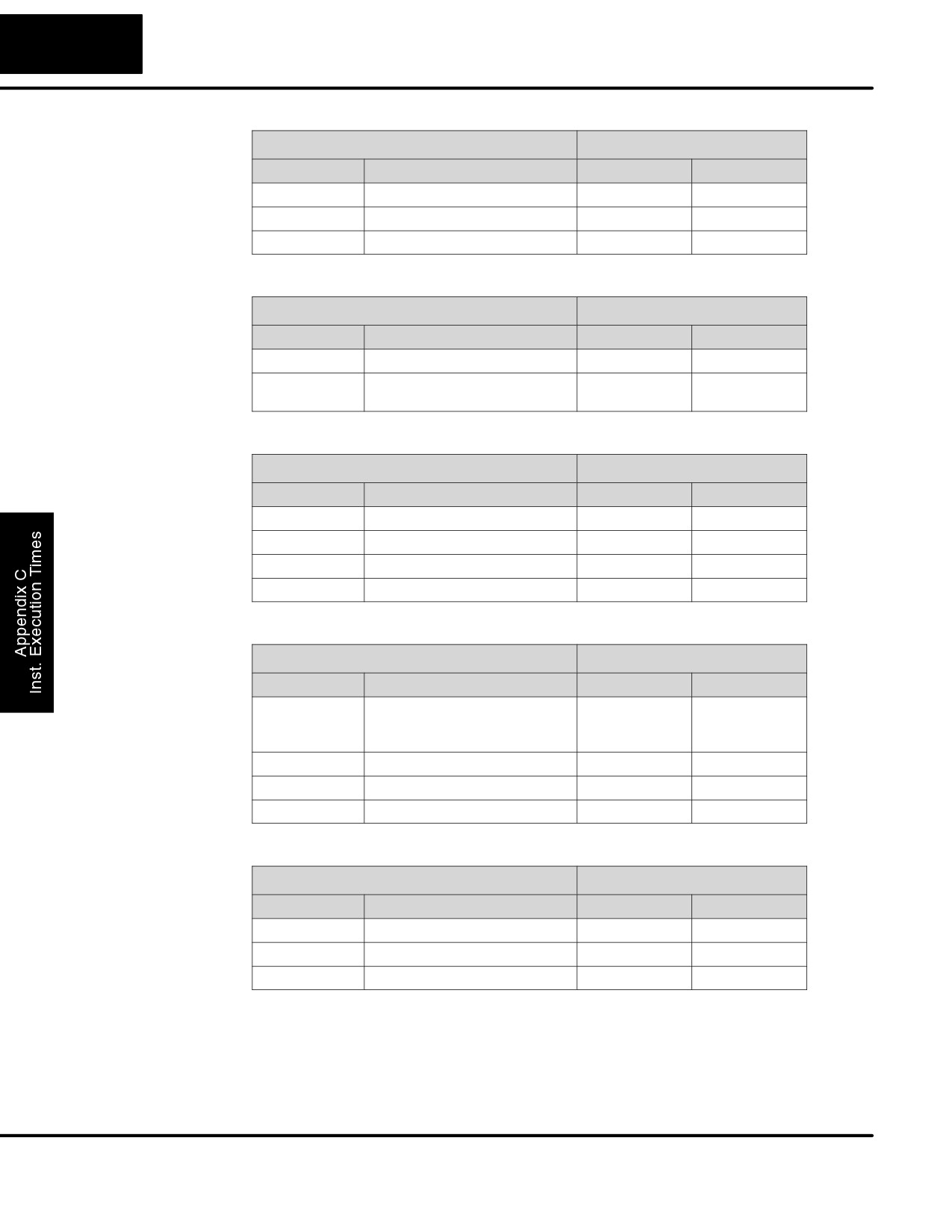
C-10
Instruction Execution Times
CPU Control
DL105
CPU Control Instructions
Instructions
Instruction
Legal Data Types
Execute
Not Execute
NOP
None
0 ms
0 ms
END
None
27 ms
27 ms
STOP
None
16 ms
5 ms
Program Control
DL105
Program Control Instructions
Instructions
Instruction
Legal Data Types
Execute
Not Execute
MLS
K (1-7)
12 ms
12 ms
MLR
K (0-6)
13 ms + 2.4 x N
13 ms + 2.4 x N
N= 1 to 7
Interrupt
DL105
Interrupt Instructions
Instructions
Instruction
Legal Data Types
Execute
Not Execute
ENI
None
9 ms
5 ms
DISI
None
8 ms
5 ms
INT
O0
0 ms
0 ms
IRT
None
1.6 ms
—
Message
DL105
Message Instructions
Instructions
Instruction
Legal Data Types
Execute
Not Execute
FAULT
V:Data Reg.
171 ms
8.4 ms
V:Bit Reg.
253 ms
8.4 ms
K:Constant
2798 ms
8.4 ms
DLBL
K
0 ms
0 ms
NCON
K
0 ms
0 ms
ACON
K
0 ms
0 ms
RLLPLUS
DL105
RLLPLUS Instructions
Instructions
Instruction
Legal Data Types
Execute
Not Execute
ISG
S
31 ms
32 ms
SG
S
31 ms
32 ms
JMP
S
14 ms
8 ms
DL105 PLC User Manual, 2nd Edition, Rev. A
D
Special Relays
In This Appendix
Ċ DL105 PLC Special Relays

D-2
Special Relays
DL105 PLC Special Relays
“Special Relays” are just contacts that are set by the CPU operating system to
indicate a particular system event has occurred. These contacts are available for
use in your ladder program. Knowing just the right special relay contact to use for a
particular situation can save lot of programming time. Since the CPU operating
system sets and clears special relay contacts, the ladder program only has to use
them as inputs in ladder logic.
Startup and
SP0
First scan
on for the first scan after a power cycle or program to run transition
Real-Time Relays
only. The relay is reset to off on the second scan. It is useful where a
function needs to be performed only on program startup.
SP1
Always ON
provides a contact to insure an instruction is executed every scan.
SP3
1 minute clock
on for 30 seconds and off for 30 seconds.
SP4
1 second clock
on for 0.5 second and off for 0.5 second.
SP5
100 ms clock
on for 50 ms. and off for 50 ms.
SP6
50 ms clock
on for 25 ms. and off for 25 ms.
SP7
Alternate scan
on every other scan.
CPU Status Relays
SP12
Terminal
on when the CPU is in the run mode.
run mode
SP16
Terminal
on when the CPU is in the program mode.
program mode
SP20
Forced
on when the STOP instruction is executed.
stop mode
SP22
Interrupt enabled
on when interrupts have been enabled using the ENI instruction.
System Monitoring
SP40
Critical error
on when a critical error such as I/O communication loss has
occurred.
SP41
Warning
on when a non critical error such as a low battery has occurred.
SP44
Program
on when a memory error such as a memory parity error has
memory error
occurred.
SP50
Fault instruction
on when a Fault Instruction is executed.
SP51
Watch Dog
on if the CPU Watch Dog timer times out.
timeout
SP52
Grammatical
on if a grammatical error has occurred either while the CPU is
error
running or if the syntax check is run. V7755 will hold the exact error
code.
SP53
Solve logic error
on if CPU cannot solve the logic.
DL105 PLC User Manual, 2nd Edition, Rev. A

D-3
Special Relays
Accumulator
SP60
Value less than
on when the accumulator value is less than the instruction value.
Status
SP61
Value equal to
on when the accumulator value is equal to the instruction value.
SP62
Greater than
on when the accumulator value is greater than the instruction value.
SP63
Zero
on when the result of the instruction is zero (in the accumulator.)
SP64
Half borrow
on when the 16 bit subtraction instruction results in a borrow.
SP65
Borrow
on when the 32 bit subtraction instruction results in a borrow.
SP66
Half carry
on when the 16 bit addition instruction results in a carry.
SP67
Carry
when the 32 bit addition instruction results in a carry.
SP70
Sign
on anytime the value in the accumulator is negative.
SP71
Invalid octal
on when an Invalid octal number was entered. This also occurs when
number
the V-memory specified by a pointer (P) is not valid.
SP73
Overflow
on if overflow occurs in the accumulator when a signed addition or
subtraction results in an incorrect sign bit.
SP75
Data error
on if a BCD number is expected and a non-BCD number is
encountered.
SP76
Load zero
on when any instruction loads a value of zero into the accumulator.
HSIO Pulse
SP100
X0 is on
X0 — on for 1 scan after a pulse on X0 occurs.
Catch Relay
Equal Relays for
SP540
Current = target value
on when the counter current value equals the value in V2320.
HSIO Mode 10
SP541
Current = target value
on when the counter current value equals the value in V2322.
Counter Presets
SP542
Current = target value
on when the counter current value equals the value in V2324.
SP543
Current = target value
on when the counter current value equals the value in V2326.
SP544
Current = target value
on when the counter current value equals the value in V2330.
SP545
Current = target value
on when the counter current value equals the value in V2332.
SP546
Current = target value
on when the counter current value equals the value in V2334.
SP547
Current = target value
on when the counter current value equals the value in V2336.
SP550
Current = target value
on when the counter current value equals the value in V2340.
SP551
Current = target value
on when the counter current value equals the value in V2342.
SP552
Current = target value
on when the counter current value equals the value in V2344.
SP553
Current = target value
on when the counter current value equals the value in V2346
SP554
Current = target value
on when the counter current value equals the value in V2350.
SP555
Current = target value
on when the counter current value equals the value in V2352.
SP556
Current = target value
on when the counter current value equals the value in V2354.
SP557
Current = target value
on when the counter current value equals the value in V2356.
SP560
Current = target value
on when the counter current value equals the value in V2360.
SP561
Current = target value
on when the counter current value equals the value in V2362.
SP562
Current = target value
on when the counter current value equals the value in V2364.
SP563
Current = target value
on when the counter current value equals the value in V2366.
SP564
Current = target value
on when the counter current value equals the value in V2370.
SP565
Current = target value
on when the counter current value equals the value in V2372.
SP566
Current = target value
on when the counter current value equals the value in V2374.
SP567
Current = target value
on when the counter current value equals the value in V2376.
DL105 PLC User Manual, 2nd Edition, Rev. A
E
PLC Memory
In This Appendix
Ċ DL105 PLC Memory