DL105 Micro PLC. User Manual (2003) - page 6
Standard RLL Instructions
5-47
Accumulator / Stack Load and Output Data Instructions
Load Address
The Load Address instruction is a 16 bit
(LDA)
instruction. It converts any octal value or
address to the HEX equivalent value and
LDA
loads the HEX value into the accumulator.
O aaa
This instruction is useful when an address
parameter is required since all addresses
for the DL105 system are in octal.
Operand Data Type
DL130 Range
aaa
Octal Address
O
All V mem. (See page 4-28)
Discrete Bit Flags
Description
SP76
on when the value loaded into the accumulator by any instruction is zero.
NOTE: Two consecutive Load instructions will place the value of the first load
instruction onto the accumulator stack.
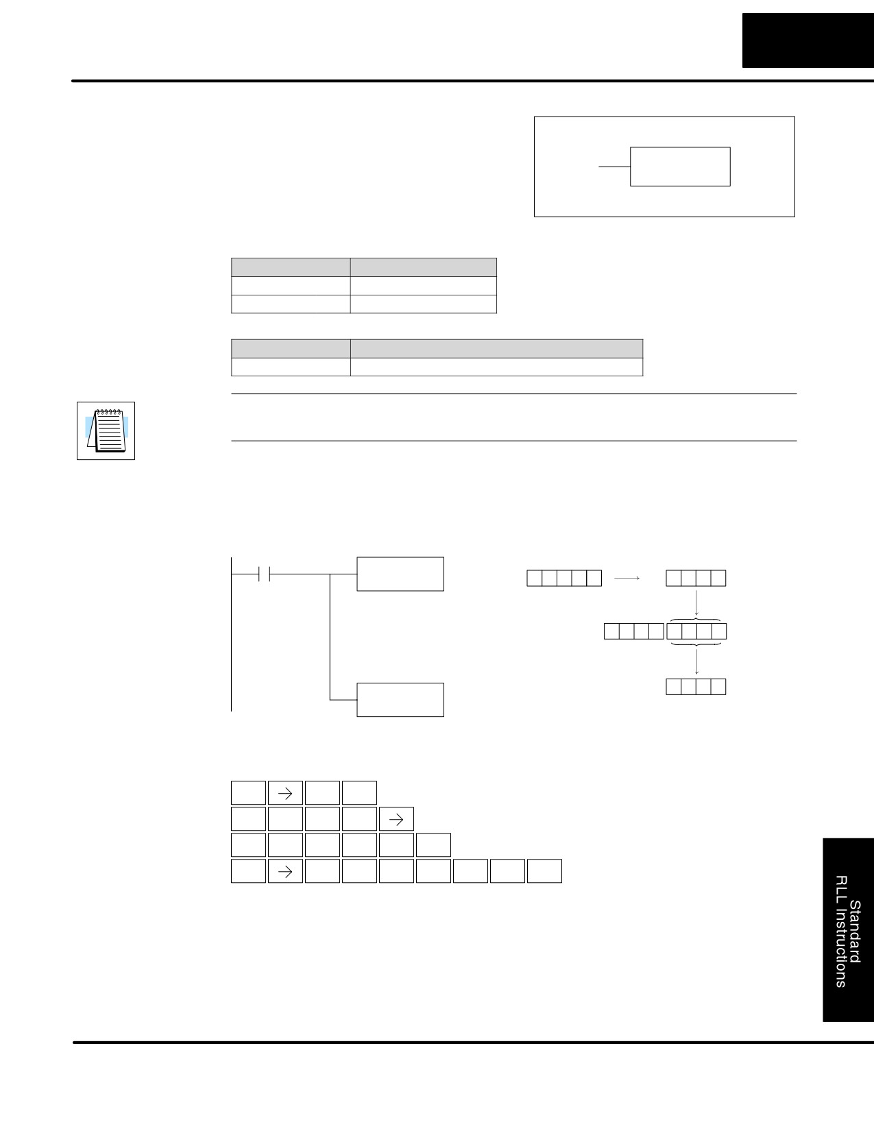
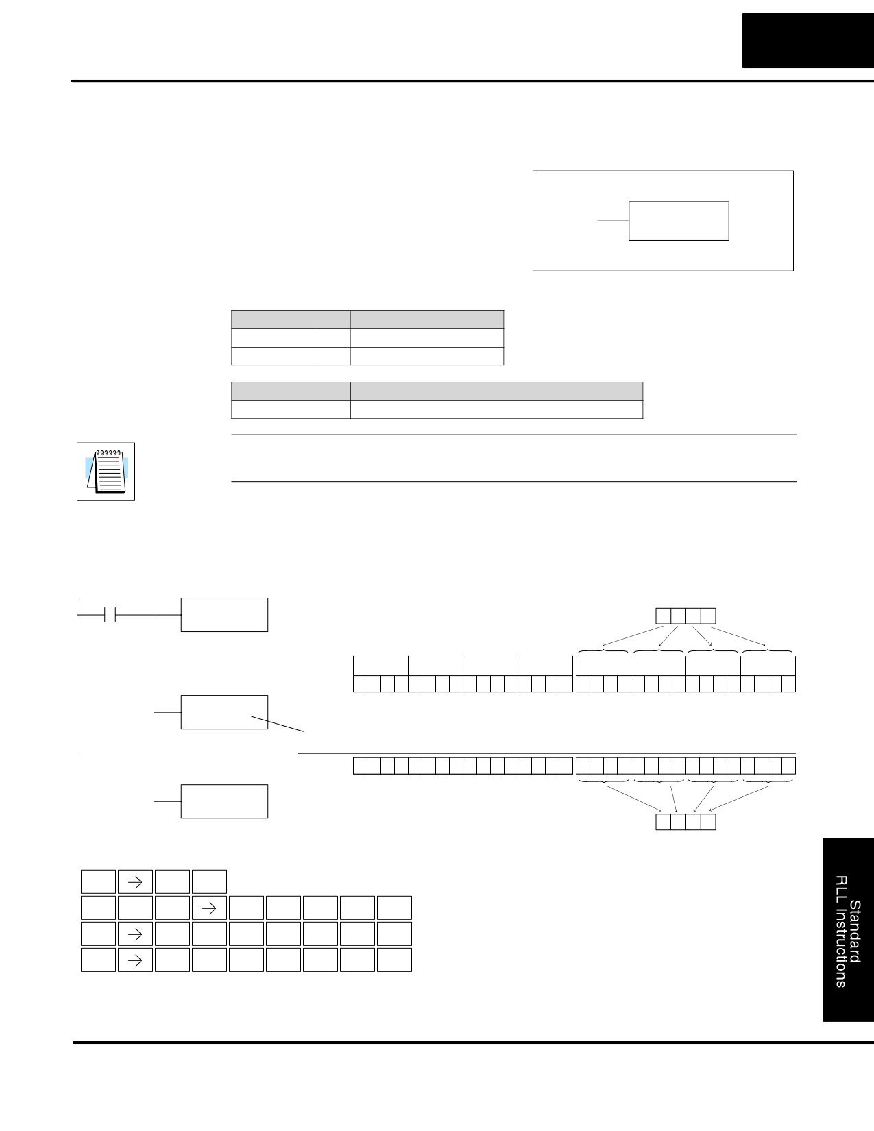
In the following example when X1 is on, the octal number 40400 will be converted to
a HEX 4100 and loaded into the accumulator using the Load Address instruction.
The value in the lower 16 bits of the accumulator is copied to V2000 using the Out
instruction.
DirectSOFT32
X1
LDA
Octal
Hexadecimal
O 40400
4
0
4
0
0
4
1
0
0
Load The HEX equivalent to
The unused accumulator
the octal number into the
bits are set to zero
lower 16 bits of the
accumulator
0
0
0
0
4
1
0
0
Acc.
4
1
0
0
OUT
V2000
V2000
Copy the value in lower 16
bits of the accumulator to
V2000
Handheld Programmer Keystrokes
$
B
ENT
STR
1
L
D
A
SHFT
ANDST
3
0
E
A
E
A
A
ENT
4
0
4
0
0
GX
V
C
A
A
A
SHFT
ENT
OUT
AND
2
0
0
0
DL105 PLC User Manual, 2nd Edition, Rev. A
Standard RLL Instructions
5-48
Accumulator / Stack Load and Output Data Instructions
Out
The Out instruction is a 16 bit instruction
(OUT)
that copies the value in the lower 16 bits of
the accumulator to a specified V memory
OUT
A aaa
location (Aaaa).
Note: See Appendix E
Operand Data Type
DL130 Range
A
aaa
V memory
V
All (See page 4-28)
Pointer
P
All V mem. (See page 4-28)
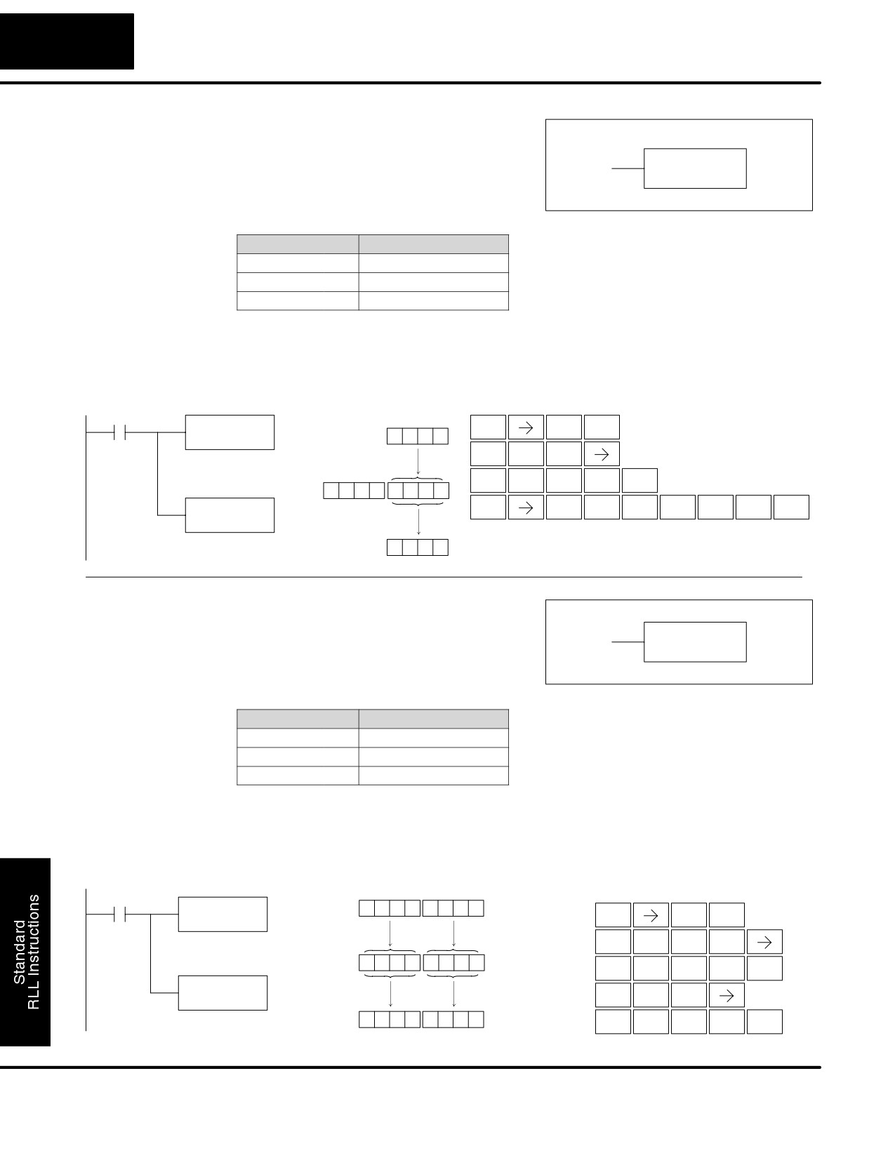
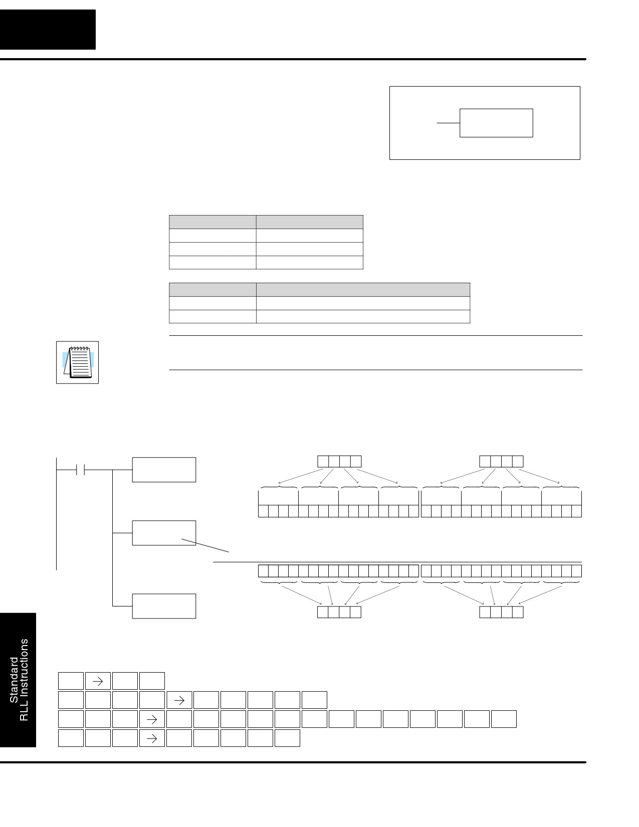
In the following example, when X1 is on, the value in V2000 will be loaded into the
lower 16 bits of the accumulator using the Load instruction. The value in the lower 16
bits of the accumulator are copied to V2010 using the Out instruction.
DirectSOFT32
Handheld Programmer Keystrokes
X1
LD
V2000
$
B
ENT
V2000
8
9
3
5
STR
1
L
D
SHFT
Load the value in V2000 into
ANDST
3
the lower 16 bits of the
The unused accumulator
accumulator
bits are set to zero
C
A
A
A
ENT
2
0
0
0
Acc.
0
0
0
0
8
9
3
5
GX
V
C
A
B
A
OUT
SHFT
ENT
OUT
AND
2
0
1
0
V2010
Copy the value in the lower
16 bits of the accumulator to
8
9
3
5
V2010
V2010
Out Double
The Out Double instruction is a 32 bit
(OUTD)
instruction that copies the value in the
OUTD
accumulator to two consecutive V memory
A aaa
locations at a specified starting location
(Aaaa). Note: See Appendix E
Operand Data Type
DL130 Range
A
aaa
V memory
V
All (See page 4-28)
Pointer
P
All V mem. (See page 4-28)
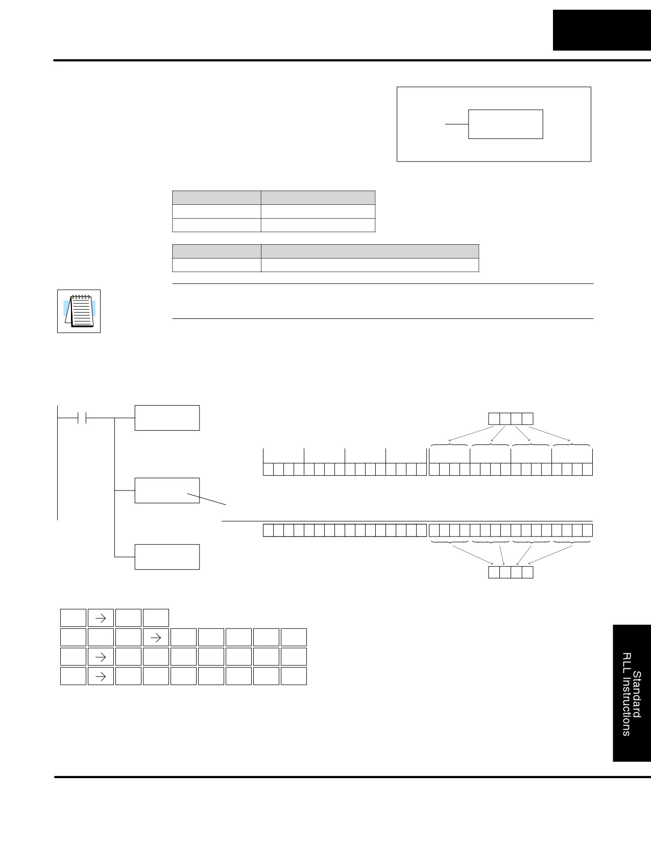
In the following example, when X1 is on, the 32 bit value in V2000 and V2001 will be
loaded into the accumulator using the Load Double instruction. The value in the
accumulator is output to V2010 and V2011 using the Out Double instruction.
DirectSOFT32
Handheld Programmer Keystrokes
V2001
V2000
X1
LDD
6
7
3
9
5
0
2
6
$
B
ENT
V2000
STR
1
Load the value in V2000 and
L
D
D
SHFT
V2001 into the accumulator
ANDST
3
3
Acc.
6
7
3
9
5
0
2
6
C
A
A
A
ENT
2
0
0
0
OUTD
GX
D
V2010
SHFT
OUT
3
Copy the value in the
6
7
3
9
5
0
2
6
C
A
B
A
ENT
accumulator to V2010 and
2
0
1
0
V2011
V2011
V2010
DL105 PLC User Manual, 2nd Edition, Rev. A
Standard RLL Instructions
5-49
Accumulator / Stack Load and Output Data Instructions
Out
The Out Formatted instruction outputs
Formatted
1-32 bits from the accumulator to the
(OUTF)
specified discrete memory locations. The
OUTF
A aaa
instruction requires a starting location
K bbb
(Aaaa) for the destination and the number
of bits (Kbbb) to be output.
Operand Data Type
DL130 Range
A
aaa
bbb
Inputs
X
0-77
--
Outputs
Y
0-77
--
Control Relays
C
0-377
--
Constant
K
--
1-32
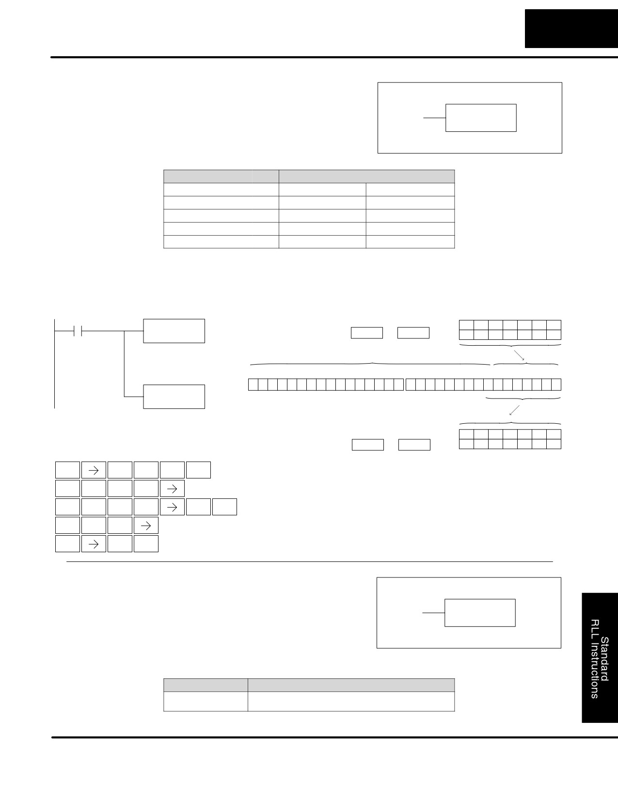
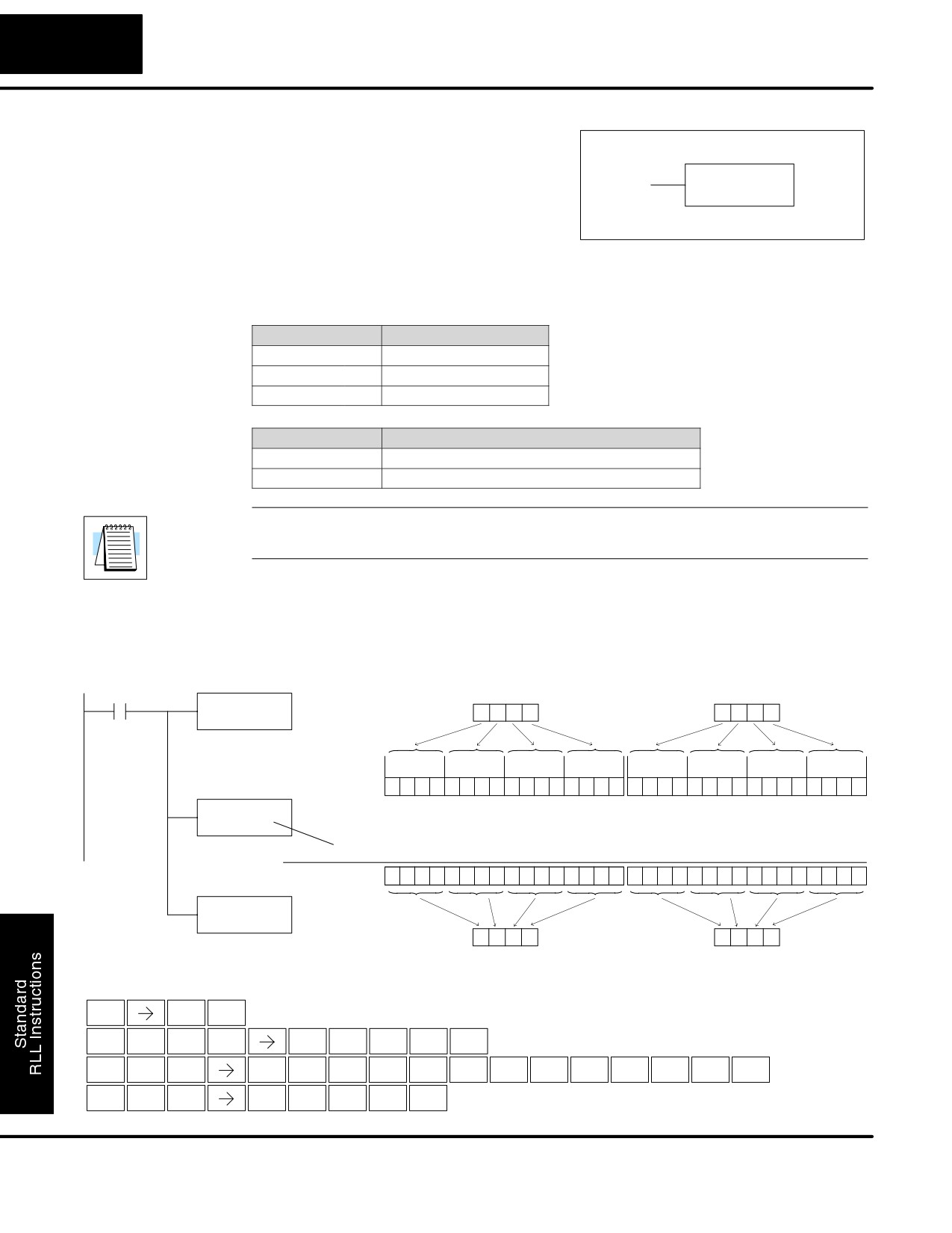
In the following example, when C0 is on, the binary pattern of C10-C16 (7 bits) will
be loaded into the accumulator using the Load Formatted instruction. The lower 7
bits of the accumulator are output to Y0-Y6 using the Out Formatted instruction.
DirectSOFT32
C0
Location
Constant
LDF
C10
C16
C15
C14
C13
C12
C11
C10
K7
C10
K7
OFF
OFF
OFF
ON
ON
ON
OFF
Load the status of 7
consecutive bits (C10-C16)
The unused accumulator bits are set to zero
into the accumulator
31 30 29 28 27 26 25 24 23 22 21 20 19 18 17 16
15 14 13 12
11 10
9
8
7
6
5
4
3
2
1
0
0
0
0
0
0
0
0
0
0
0
0
0
0
0
0
0
0
0
0
0
0
0
0
0
0
0
0
0
1
1
1
0
OUTF
Y0
Accumulator
K7
Copy the value of the
specified number of bits
from the accumulator to
Y20-Y26
Location
Constant
Y26
Y25
Y24
Y23
Y22
Y21
Y20
Y0
K7
OFF
OFF
OFF
ON
ON
ON
OFF
Handheld Programmer Keystrokes
$
C
A
SHFT
ENT
STR
2
0
L
D
F
SHFT
ANDST
3
5
SHFT
C
B
A
H
ENT
2
1
0
7
GX
F
SHFT
OUT
5
A
H
ENT
0
7
Pop
The Pop instruction moves the value from
(POP)
the first level of the accumulator stack (32
bits) to the accumulator and shifts each
POP
value in the stack up one level.
Discrete Bit Flags
Description
SP63
on when the result of the instruction causes the value in the accumulator
to be zero.
DL105 PLC User Manual, 2nd Edition, Rev. A
Standard RLL Instructions
5-50
Accumulator / Stack Load and Output Data Instructions
Pop Instruction
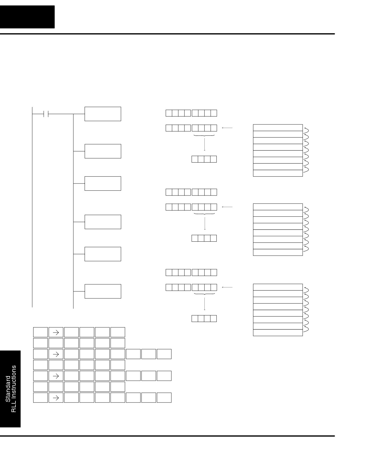
In the example below, when C0 is on, the value 4545 that was on top of the stack is
Continued
moved into the accumulator using the Pop instruction The value is output to V2000
using the Out instruction. The next Pop moves the value 3792 into the accumulator
and outputs the value to V2001. The last Pop moves the value 7930 into the
accumulator and outputs the value to V2002. Please note if the value in the stack
were greater than 16 bits (4 digits) the Out Double instruction would be used and 2 V
memory locations for each Out Double must be allocated.
DirectSOFT32
Previous Acc. value
C0
POP
Acc.
X
X
X
X
X
X
X
X
Current Acc. value
Accumulator Stack
Pop the 1st. value on the stack into the
Acc.
0
0
0
0
4
5
4
5
Level 1
0
0
0
0
3
7
9
2
accumulator and move stack values
up one location
Level 2
0
0
0
0
7
9
3
0
Level 3
X
X X X X X X
X
OUT
Level 4
X
X X X X X X
X
V2000
Level 5
X
X X X X X X
X
V2000
4
5
4
5
Level 6
X
X X X X X X
X
Copy the value in the lower 16 bits of
the accumulator to V2000
Level 7
X
X X X X X X
X
Level 8
X
X X X X X X
X
POP
Previous Acc. value
Acc.
0
0
0
0
4
5
4
5
Pop the 1st. value on the stack into the
Current Acc. value
Accumulator Stack
accumulator and move stack values
up one location
Acc.
0
0
0
0
3
7
9
2
Level 1
0
0
0
0
7
9
3
0
Level 2
X
X X X X X X
X
OUT
Level 3
X
X X X X X X
X
V2001
Level 4
X
X X X X X X
X
Copy the value in the lower 16 bits of
Level 5
X
X X X X X X
X
the accumulator to V2001
3
7
9
2
V2001
Level 6
X
X X X X X X
X
Level 7
X
X X X X X X
X
POP
Level 8
X
X X X X X X
X
Pop the 1st. value on the stack into the
Previous Acc. value
accumulator and move stack values
Acc.
0
0
0
0
3
7
9
2
up one location
Current Acc. value
Accumulator Stack
OUT
Acc.
0
0
0
0
7
9
3
0
Level 1
X
X X X X X X
X
V2002
Level 2
X
X X X X X X
X
Level 3
X
X X X X X X
X
Copy the value in the lower 16 bits of
the accumulator to V2002
Level 4
X
X X X X X X
X
Level 5
X
X X X X X X
X
V2002
7
9
3
0
Level 6
X
X X X X X X
X
Handheld Programmer Keystrokes
Level 7
X
X X X X X X
X
$
C
A
SHFT
ENT
Level 8
X
X X X X X X
X
STR
2
0
P
O
P
SHFT
SHFT
ENT
CV
INST#
CV
GX
V
C
A
A
A
SHFT
ENT
OUT
AND
2
0
0
0
P
O
P
SHFT
SHFT
ENT
CV
INST#
CV
GX
V
C
A
A
B
SHFT
ENT
OUT
AND
2
0
0
1
P
O
P
SHFT
SHFT
ENT
CV
INST#
CV
GX
V
C
A
A
C
SHFT
ENT
OUT
AND
2
0
0
2
DL105 PLC User Manual, 2nd Edition, Rev. A
Standard RLL Instructions
5-51
Accumulator Logic Instructions
Logical Instructions (Accumulator)
And
The And instruction is a 16 bit instruction
(AND)
that logically ands the value in the lower
16 bits of the accumulator with a
AND
specified V memory location (Aaaa). The
A aaa
result resides in the accumulator. The
discrete status flag indicates if the result
of the And is zero.
Operand Data Type
DL130 Range
A
aaa
V memory
V
All (See page 4-28)
Discrete Bit Flags
Description
SP63
Will be on if the result in the accumulator is zero
NOTE: The status flags are only valid until another instruction that uses the same
flags is executed.
In the following example, when X1 is on, the value in V2000 will be loaded into the
accumulator using the Load instruction. The value in the accumulator is anded
with the value in V2006 using the And instruction. The value in the lower 16 bits of the
accumulator is output to V2010 using the Out instruction.
DirectSOFT
X1
V2000
LD
2
8
7
A
V2000
Load the value in V2000 into
The upper 16 bits of the accumulator
the lower 16 bits of the
will be set to 0
accumulator
31 30 29 28
27 26 25 24
23 22 21 20
19 18 17 16
15 14 13 12
11 10
9
8
7
6
5
4
3
2
1
0
Acc.
0
0
0
0
0
0
0
0
0
0
0
0
0
0
0
0
0
0
1
0
1
0
0
0
0
1
1
1
1
0
1
0
AND
V2006
Acc.
0
0
0
0
0
0
0
0
0
0
0
0
0
0
0
0
0
0
1
0
1
0
0
0
0
1
1
1
1
0
1
0
AND the value in the
6A38
accumulator with
AND (V2006)
0
0
0
0
0
0
0
0
0
0
0
0
0
0
0
0
0
1
1
0
1
0
1
0
0
0
1
1
1
0
0
0
the value in V2006
Acc.
0
0
0
0
0
0
0
0
0
0
0
0
0
0
0
0
0
0
1
0
1
0
0
0
0
0
1
1
1
0
0
0
OUT
V2010
2
8
3
8
Copy the lower 16 bits of the
accumulator to V2010
V2010
Handheld Programmer Keystrokes
$
B
ENT
STR
1
L
D
C
A
A
A
SHFT
ENT
ANDST
3
2
0
0
0
V
SHFT
V
C
A
A
G
ENT
AND
AND
2
0
0
6
GX
V
C
A
B
A
SHFT
ENT
OUT
AND
2
0
1
0
DL105 PLC User Manual, 2nd Edition, Rev. A
Standard RLL Instructions
5-52
Accumulator Logic Instructions
And Double
The And Double is a 32 bit instruction that
(ANDD)
logically ands the value in the
accumulator with two consecutive V
ANDD
K aaa
memory locations or an 8 digit (max.)
constant value
(Aaaa). The result
resides in the accumulator. Discrete
status flags indicate if the result of the
And Double is zero or a negative number
(the most significant bit is on).
Operand Data Type
DL130 Range
aaa
V memory
V
All (See page 4-28)
Constant
K
0-FFFFFFFF
Discrete Bit Flags
Description
SP63
Will be on if the result in the accumulator is zero
SP70
Will be on is the result in the accumulator is negative
NOTE: The status flags are only valid until another instruction that uses the same
flags is executed.
In the following example, when X1 is on, the value in V2000 and V2001 will be loaded
into the accumulator using the Load Double instruction. The value in the
accumulator is anded with 36476A38 using the And double instruction. The value in
the accumulator is output to V2010 and V2011 using the Out Double instruction.
DirectSOFT
V2001
V2000
X1
5
4
7
E
2
8
7
A
LDD
V2000
Load the value in V2000 and
V2001 into the accumulator
31 30 29 28
27 26 25 24
23 22 21 20
19 18 17 16
15 14 13 12
11 10
9
8
7
6
5
4
3
2
1
0
Acc.
0
1
0
1
0
1
0
0
0
1
1
1
1
1
1
0
0
0
1
0
1
0
0
0
0
1
1
1
1
0
1
0
ANDD
K36476A38
Acc.
0
1
0
1
0
1
0
0
0
1
1
1
1
1
1
0
0
0
1
0
1
0
0
0
0
1
1
1
1
0
1
0
AND the value in the
accumulator with
AND 36476A38
0
0
1
1
0
1
1
0
0
1
0
0
0
1
1
1
0
1
1
0
1
0
1
0
0
0
1
1
1
0
0
0
the constant value
36476A38
Acc.
0
0
0
1
0
1
0
0
0
1
0
0
0
1
1
0
0
0
1
0
1
0
0
0
0
0
1
1
1
0
0
0
OUTD
V2010
1
4
4
6
2
8
3
8
Copy the value in the
V2011
V2010
accumulator to V2010 and
V2011
Handheld Programmer Keystrokes
$
B
ENT
STR
1
L
D
D
C
A
A
A
SHFT
ENT
ANDST
3
3
2
0
0
0
V
D
K
D
G
E
H
G
A
D
I
SHFT
SHFT
SHFT
SHFT
ENT
AND
3
JMP
3
6
4
7
6
0
3
8
GX
D
C
A
B
A
SHFT
ENT
OUT
3
2
0
1
0
DL105 PLC User Manual, 2nd Edition, Rev. A
Standard RLL Instructions
5-53
Accumulator Logic Instructions
Or
The Or instruction is a 16 bit instruction
(OR)
that logically ors the value in the lower 16
bits of the accumulator with a specified V
OR
memory location
(Aaaa). The result
A aaa
resides in the accumulator. The discrete
status flag indicates if the result of the Or
is zero.
Operand Data Type
DL130 Range
A
aaa
V memory
V
All (See page 4-28)
Discrete Bit Flags
Description
SP63
Will be on if the result in the accumulator is zero
NOTE: The status flags are only valid until another instruction that uses the same
flags is executed.
In the following example, when X1 is on, the value in V2000 will be loaded into the
accumulator using the Load instruction. The value in the accumulator is ored with
V2006 using the Or instruction. The value in the lower 16 bits of the accumulator are
output to V2010 using the Out instruction.
DirectSOFT
X1
V2000
LD
2
8
7
A
V2000
Load the value in V2000 into
The upper 16 bits of the accumulator
the lower 16 bits of the
will be set to 0
accumulator
31 30 29 28
27 26 25 24
23 22 21 20
19 18
17
16
15
14
13
12
11
10
9
8
7
6
5
4
3
2
1
0
Acc.
0
0
0
0
0
0
0
0
0
0
0
0
0
0
0
0
0
0
1
0
1
0
0
0
0
1
1
1
1
0
1
0
OR
V2006
Acc.
0
0
0
0
0
0
0
0
0
0
0
0
0
0
0
0
0
0
1
0
1
0
0
0
0
1
1
1
1
0
1
0
Or the value in the
6A38
accumulator with
OR (V2006)
0
0
0
0
0
0
0
0
0
0
0
0
0
0
0
0
0
1
1
0
1
0
1
0
0
0
1
1
1
0
0
0
the value in V2006
Acc.
0
0
0
0
0
0
0
0
0
0
0
0
0
0
0
0
0
1
1
0
1
0
1
0
0
1
1
1
1
0
1
0
OUT
V2010
6
A
7
A
Copy the value in the lower
16 bits of the accumulator to
V2010
V2010
Handheld Programmer Keystrokes
$
B
ENT
STR
1
L
D
C
A
A
A
SHFT
ENT
ANDST
3
2
0
0
0
Q
SHFT
V
C
A
A
G
ENT
OR
AND
2
0
0
6
GX
V
C
A
B
A
SHFT
ENT
OUT
AND
2
0
1
0
DL105 PLC User Manual, 2nd Edition, Rev. A
Standard RLL Instructions
5-54
Accumulator Logic Instructions
Or Double
The Or Double is a 32 bit instruction that
(ORD)
ors the value in the accumulator with the
value
(Aaaa), which is either two
ORD
consecutive V memory locations or an 8
K aaa
digit
(max.) constant value. The result
resides in the accumulator. Discrete
status flags indicate if the result of the Or
Double is zero or a negative number (the
most significant bit is on).
Operand Data Type
DL130 Range
aaa
V memory
V
All (See page 4-28)
Constant
K
0-FFFFFFFF
Discrete Bit Flags
Description
SP63
Will be on if the result in the accumulator is zero
SP70
Will be on is the result in the accumulator is negative
NOTE: The status flags are only valid until another instruction that uses the same
flags is executed.
In the following example, when X1 is on, the value in V2000 and V2001 will be loaded
into the accumulator using the Load Double instruction. The value in the
accumulator is ored with 36476A38 using the Or Double instruction. The value in the
accumulator is output to V2010 and V2011 using the Out Double instruction.
DirectSOFT
X1
V2001
V2000
LDD
5
4
7
E
2
8
7
A
V2000
Load the value in V2000 and
V2001 into accumulator
31 30 29 28
27 26 25 24
23 22 21 20
19 18 17 16
15 14 13 12
11 10
9
8
7
6
5
4
3
2
1
0
Acc.
0
1
0
1
0
1
0
0
0
1
1
1
1
1
1
0
0
0
1
0
1
0
0
0
0
1
1
1
1
0
1
0
ORD
K36476A38
Acc.
0
1
0
1
0
1
0
0
0
1
1
1
1
1
1
0
0
0
1
0
1
0
0
0
0
1
1
1
1
0
1
0
OR the value in the
accumulator with
OR 36476A38
0
0
1
1
0
1
1
0
0
1
0
0
0
1
1
1
0
1
1
0
1
0
1
0
0
0
1
1
1
0
0
0
the constant value
36476A38
Acc.
0
1
1
1
0
1
1
0
0
1
1
1
1
1
1
1
0
1
1
0
1
0
1
0
0
1
1
1
1
0
1
0
OUTD
V2010
7
6
7
F
6
A
7
A
Copy the value in the
accumulator to V2010 and
V2011
V2010
V2011
Handheld Programmer Keystrokes
$
B
ENT
STR
1
L
D
D
C
A
A
A
SHFT
ENT
ANDST
3
3
2
0
0
0
Q
D
K
D
G
E
H
G
A
D
I
SHFT
SHFT
SHFT
SHFT
ENT
OR
3
JMP
3
6
4
7
6
0
3
8
GX
D
C
A
B
A
SHFT
ENT
OUT
3
2
0
1
0
DL105 PLC User Manual, 2nd Edition, Rev. A
Standard RLL Instructions
5-55
Accumulator Logic Instructions
Exclusive Or
The Exclusive Or instruction is a 16 bit
(XOR)
instruction that performs an exclusive or
of the value in the lower 16 bits of the
XOR
accumulator and a specified V memory
A aaa
location (Aaaa). The result resides in the
in the accumulator. The discrete status
flag indicates if the result of the XOR is
zero.
Operand Data Type
DL130 Range
A
aaa
V memory
V
All (See page 4-28)
Discrete Bit Flags
Description
SP63
Will be on if the result in the accumulator is zero
NOTE: The status flags are only valid until another instruction that uses the same
flags is executed.
In the following example, when X1 is on, the value in V2000 will be loaded into the
accumulator using the Load instruction. The value in the accumulator is exclusive
ored with V2006 using the Exclusive Or instruction. The value in the lower 16 bits of
the accumulator are output to V2010 using the Out instruction.
DirectSOFT
X1
V2000
LD
2
8
7
A
V2000
Load the value in V2000 into
The upper 16 bits of the accumulator
the lower 16 bits of the
will be set to 0
accumulator
31 30 29 28
27 26 25 24
23 22 21 20
19 18 17 16
15 14 13 12
11 10
9
8
7
6
5
4
3
2
1
0
Acc.
0
0
0
0
0
0
0
0
0
0
0
0
0
0
0
0
0
0
1
0
1
0
0
0
0
1
1
1
1
0
1
0
XOR
V2006
Acc.
0
0
0
0
0
0
0
0
0
0
0
0
0
0
0
0
0
0
1
0
1
0
0
0
0
1
1
1
1
0
1
0
XOR the value in the
6A38
accumulator with
XOR (V2006)
0
0
0
0
0
0
0
0
0
0
0
0
0
0
0
0
0
1
1
0
1
0
1
0
0
0
1
1
1
0
0
0
the value in V2006
Acc.
0
0
0
0
0
0
0
0
0
0
0
0
0
0
0
0
0
1
0
0
0
0
1
0
0
1
0
0
0
0
1
0
OUT
V2010
4
2
4
2
Copy the lower 16 bits of the
accumulator to V2010
V2010
Handheld Programmer Keystrokes
$
SHFT
X
B
ENT
STR
SET
1
L
D
V
C
A
A
A
SHFT
SHFT
ENT
ANDST
3
AND
2
0
0
0
X
Q
V
C
A
A
G
SHFT
SHFT
SHFT
ENT
SET
OR
AND
2
0
0
6
GX
V
C
A
B
A
SHFT
ENT
OUT
AND
2
0
1
0
DL105 PLC User Manual, 2nd Edition, Rev. A
Standard RLL Instructions
5-56
Accumulator Logic Instructions
Exclusive Or
The Exclusive OR Double is a 32 bit
Double
instruction that performs an exclusive or
(XORD)
of the value in the accumulator and the
XORD
value
(Aaaa), which is either two
K aaa
consecutive V memory locations or an 8
digit (max.) constant. The result resides
in the accumulator. Discrete status flags
indicate if the result of the Exclusive Or
Double is zero or a negative number (the
most significant bit is on).
Operand Data Type
DL130 Range
A
aaa
V memory
V
All (See page 4-28)
Constant
K
0-FFFFFFFF
Discrete Bit Flags
Description
SP63
Will be on if the result in the accumulator is zero
SP70
Will be on is the result in the accumulator is negative
NOTE: The status flags are only valid until another instruction that uses the same
flags is executed.
In the following example, when X1 is on, the value in V2000 and V2001 will be loaded
into the accumulator using the Load Double instruction. The value in the
accumulator is exclusively ored with 36476A38 using the Exclusive Or Double
instruction. The value in the accumulator is output to V2010 and V2011 using the Out
Double instruction.
DirectSOFT
V2001
V2000
X1
5
4
7
E
2
8
7
A
LDD
V2000
Load the value in V2000 and
V2001 into the accumulator
31 30 29 28
27 26 25 24
23 22 21 20
19 18 17 16
15 14 13 12
11 10
9
8
7
6
5
4
3
2
1
0
XORD
Acc.
0
1
0
1
0
1
0
0
0
1
1
1
1
1
1
0
0
0
1
0
1
0
0
0
0
1
1
1
1
0
1
0
K36476A38
XORD the value in the
Acc.
0
1
0
1
0
1
0
0
0
1
1
1
1
1
1
0
0
0
1
0
1
0
0
0
0
1
1
1
1
0
1
0
accumulator with
the constant value
36476A38
XORD 36476A38
0
0
1
1
0
1
1
0
0
1
0
0
0
1
1
1
0
1
1
0
1
0
1
0
0
0
1
1
1
0
0
0
OUTD
Acc.
0
1
1
0
0
0
1
0
0
0
1
1
1
0
0
1
0
1
0
0
0
0
1
0
0
1
0
0
0
0
1
0
V2010
Copy the value in the
accumulator to V2010
and V2011
6
2
3
9
4
2
4
2
Handheld Programmer Keystrokes
V2011
V2010
$
B
ENT
STR
1
L
D
D
C
A
A
A
SHFT
ENT
ANDST
3
3
2
0
0
0
X
Q
D
K
SHFT
SHFT
SHFT
SET
OR
3
JMP
D
G
E
H
G
A
D
I
SHFT
SHFT
ENT
3
6
4
7
6
0
3
8
GX
D
C
A
B
A
SHFT
ENT
OUT
3
2
0
1
0
DL105 PLC User Manual, 2nd Edition, Rev. A
Standard RLL Instructions
5-57
Accumulator Logic Instructions
Compare
The compare instruction is a
16 bit
(CMP)
instruction that compares the value in the
lower 16 bits of the accumulator with the
CMP
A aaa
value in a specified V memory location
(Aaaa). The corresponding status flag
will be turned on indicating the result of
the comparison.
Operand Data Type
DL130 Range
A
aaa
V memory
V
All (See page 4-28)
Discrete Bit Flags
Description
SP60
On when the value in the accumulator is less than the instruction value.
SP61
On when the value in the accumulator is equal to the instruction value.
SP62
On when the value in the accumulator is greater than the instruction
value.
NOTE: The status flags are only valid until another instruction that uses the same
flags is executed.
In the following example when X1 is on, the constant 4526 will be loaded into the
lower 16 bits of the accumulator using the Load instruction. The value in the
accumulator is compared with the value in V2000 using the Compare instruction.
The corresponding discrete status flag will be turned on indicating the result of the
comparison. In this example, if the value in the accumulator is less than the value
specified in the Compare instruction, SP60 will turn on energizing C30.
DirectSOFT
X1
Constant
LD
K4526
4
5
2
6
Load the constant value
The unused accumulator
4526 into the lower 16 bits of
bits are set to zero
the accumulator
0
0
0
0
4
5
2
6
Acc.
Compared
with
CMP
V2000
8
9
4
5
Compare the value in the
V2000
accumulator with the value
in V2000
SP60
C30
Handheld Programmer Keystrokes
$
B
ENT
STR
1
L
D
K
E
F
C
G
SHFT
SHFT
ENT
ANDST
3
JMP
4
5
2
6
C
M
P
C
A
A
A
SHFT
SHFT
ENT
2
ORST
CV
2
0
0
0
$
SP
G
A
SHFT
ENT
STR
STRN
6
0
GX
C
D
A
SHFT
ENT
OUT
2
3
0
DL105 PLC User Manual, 2nd Edition, Rev. A
Standard RLL Instructions
5-58
Accumulator Logic Instructions
Compare Double
The Compare Double instruction is a
(CMPD)
32-bit instruction that compares the
value in the accumulator with the value
CMPD
(Aaaa), which is either two consecutive V
A aaa
memory locations or an 8-digit (max.)
constant. The corresponding status flag
will be turned on indicating the result of
the comparison.
Operand Data Type
DL130 Range
A
aaa
V memory
V
All (See page 4-28)
Constant
K
1-FFFFFFFF
Discrete Bit Flags
Description
SP60
On when the value in the accumulator is less than the instruction value.
SP61
On when the value in the accumulator is equal to the instruction value.
SP62
On when the value in the accumulator is greater than the instruction
value.
NOTE: The status flags are only valid until another instruction that uses the same
flags is executed.
In the following example when X1 is on, the value in V2000 and V2001 will be loaded
into the accumulator using the Load Double instruction. The value in the
accumulator is compared with the value in V2010 and V2011 using the CMPD
instruction. The corresponding discrete status flag will be turned on indicating the
result of the comparison. In this example, if the value in the accumulator is less than
the value specified in the Compare instruction, SP60 will turn on energizing C30.
DirectSOFT
X1
V2001
V2000
LDD
4
5
2
6
7
2
9
9
V2000
Load the value in V2000 and
V2001 into the accumulator
4
5
2
6
7
2
9
9
Acc.
Compared
CMPD
with
V2010
6
7
3
9
5
0
2
6
Compare the value in the
accumulator with the value
V2011
V2010
in V2010 and V2011
SP60
C30
Handheld Programmer Keystrokes
$
B
ENT
STR
1
L
D
D
C
A
A
A
SHFT
ENT
ANDST
3
3
2
0
0
0
C
M
P
D
C
A
B
A
SHFT
SHFT
ENT
2
ORST
CV
3
2
0
1
0
$
SP
G
A
SHFT
ENT
STR
STRN
6
0
GX
C
D
A
SHFT
ENT
OUT
2
3
0
DL105 PLC User Manual, 2nd Edition, Rev. A
Standard RLL Instructions
5-59
Math Instructions
Math Instructions
Add
Add is a 16 bit instruction that adds a
(ADD)
BCD value in the accumulator with a
BCD value in a V memory location
ADD
(Aaaa). The result resides in the
A aaa
accumulator.
Operand Data Type
DL130 Range
A
aaa
V memory
V
All (See page 4-28)
Discrete Bit Flags
Description
SP63
On when the result of the instruction causes the value in the accumulator
to be zero.
SP66
On when the 16 bit addition instruction results in a carry.
SP67
On when the 32 bit addition instruction results in a carry.
SP70
On anytime the value in the accumulator is negative.
SP75
On when a BCD instruction is executed and a NON-BCD number was
encountered.
NOTE: The status flags are only valid until another instruction that uses the same
flags is executed.
In the following example, when X1 is on, the value in V2000 will be loaded into the
accumulator using the Load instruction. The value in the lower 16 bits of the
accumulator are added to the value in V2006 using the Add instruction. The value in
the accumulator is copied to V2010 using the Out instruction.
DirectSOFT32
V2000
X1
4
9
3
5
LD
V2000
Load the value in V2000 into
the lower 16 bits of the
The unused accumulator
accumulator
bits are set to zero
0
0
0
0
4
9
3
5
(Accumulator)
ADD
+
2
5
0
0
(V2006)
V2006
Acc.
7
4
3
5
Add the value in the lower
16 bits of the accumulator
with the value in V2006
OUT
V2010
7
4
3
5
Copy the value in the lower
V2010
16 bits of the accumulator to
V2010
Handheld Programmer Keystrokes
$
B
ENT
STR
1
L
D
C
A
A
A
SHFT
ENT
ANDST
3
2
0
0
0
A
D
D
C
A
A
G
SHFT
ENT
0
3
3
2
0
0
6
GX
SHFT
V
C
A
B
A
ENT
OUT
AND
2
0
1
0
DL105 PLC User Manual, 2nd Edition, Rev. A
Standard RLL Instructions
5-60
Math Instructions
Add Double
Add Double is a 32 bit instruction that
(ADDD)
adds the BCD value in the accumulator
with a BCD value (Aaaa), which is either
ADDD
two consecutive V memory locations or
A aaa
an 8-digit (max.) BCD constant. The
result resides in the accumulator.
Operand Data Type
DL130 Range
A
aaa
V memory
V
All (See page 4-28)
Constant
K
0-99999999
Discrete Bit Flags
Description
SP63
On when the result of the instruction causes the value in the accumulator
to be zero.
SP66
On when the 16 bit addition instruction results in a carry.
SP67
On when the 32 bit addition instruction results in a carry.
SP70
On anytime the value in the accumulator is negative.
SP75
On when a BCD instruction is executed and a NON-BCD number was
encountered.
NOTE: The status flags are only valid until another instruction that uses the same
flags is executed.
In the following example, when X1 is on, the value in V2000 and V2001 will be loaded
into the accumulator using the Load Double instruction. The value in the
accumulator is added with the value in V2006 and V2007 using the Add Double
instruction. The value in the accumulator is copied to V2010 and V2011 using the
Out Double instruction.
DirectSOFT32
V2001
V2000
X1
6
7
3
9
5
0
2
6
LDD
V2000
Load the value in V2000 and
V2001 into the accumulator
6
7
3
9
5
0
2
6
(Accumulator)
ADDD
+
2
0
0
0
4
0
4
6
(V2006 and V2007)
V2006
Acc.
8
7
3
9
9
0
7
2
Add the value in the
accumulator with the value
in V2006 and V2007
OUTD
V2010
8
7
3
9
9
0
7
2
Copy the value in the
V2011
V2010
accumulator to V2010 and
V2011
Handheld Programmer Keystrokes
$
B
ENT
STR
1
L
D
D
C
A
A
A
SHFT
ENT
ANDST
3
3
2
0
0
0
SHFT
A
D
D
D
C
A
A
G
ENT
0
3
3
3
2
0
0
6
GX
D
V
C
A
B
A
SHFT
SHFT
ENT
OUT
3
AND
2
0
1
0
DL105 PLC User Manual, 2nd Edition, Rev. A
Standard RLL Instructions
5-61
Math Instructions
Subtract
Subtract is a
16 bit instruction that
(SUB)
subtracts the BCD value (Aaaa) in a V
memory location from the BCD value in
SUB
the lower 16 bits of the accumulator. The
A aaa
result resides in the accumulator.
Operand Data Type
DL130 Range
A
aaa
V memory
V
All (See page 4-28)
Discrete Bit Flags
Description
SP63
On when the result of the instruction causes the value in the accumulator
to be zero.
SP64
On when the 16 bit subtraction instruction results in a borrow.
SP65
On when the 32 bit subtraction instruction results in a borrow.
SP70
On anytime the value in the accumulator is negative.
SP75
On when a BCD instruction is executed and a NON-BCD number was
encountered.
NOTE: The status flags are only valid until another instruction that uses the same
flags is executed.
In the following example, when X1 is on, the value in V2000 will be loaded into the
accumulator using the Load instruction. The value in V2006 is subtracted from the
value in the accumulator using the Subtract instruction. The value in the accumulator
is copied to V2010 using the Out instruction.
DirectSOFT32
V2000
2
4
7
5
X1
LD
V2000
Load the value in V2000 into
The unused accumulator
the lower 16 bits of the
bits are set to zero
accumulator
0
0
0
0
2
4
7
5
(Accumulator)
SUB
y
1
5
9
2
(V2006)
V2006
Acc.
0
8
8
3
Subtract the value in V2006
from the value in the lower
16 bits of the accumulator
OUT
0
8
8
3
V2010
V2010
Copy the value in the lower
16 bits of the accumulator to
V2010
Handheld Programmer Keystrokes
$
B
ENT
STR
1
L
D
C
A
A
A
SHFT
ENT
ANDST
3
2
0
0
0
S
U
B
V
C
A
A
G
SHFT
SHFT
ENT
RST
ISG
1
AND
2
0
0
6
GX
V
C
A
B
A
SHFT
ENT
OUT
AND
2
0
1
0
DL105 PLC User Manual, 2nd Edition, Rev. A
Standard RLL Instructions
5-62
Math Instructions
Subtract Double
Subtract Double is a 32 bit instruction that
(SUBD)
subtracts the BCD value (Aaaa), which is
either two consecutive V memory
SUBD
A aaa
locations or an 8-digit (max.) constant,
from the BCD value in the accumulator.
The result resides in the accumulator.
Operand Data Type
DL130 Range
A
aaa
V memory
V
All (See page 4-28)
Constant
K
0-99999999
Discrete Bit Flags
Description
SP63
On when the result of the instruction causes the value in the accumulator
to be zero.
SP64
On when the 16 bit subtraction instruction results in a borrow.
SP65
On when the 32 bit subtraction instruction results in a borrow.
SP70
On anytime the value in the accumulator is negative.
SP75
On when a BCD instruction is executed and a NON-BCD number was
encountered.
NOTE: The status flags are only valid until another instruction that uses the same
flags is executed.
In the following example, when X1 is on, the value in V2000 and V2001 will be loaded
into the accumulator using the Load Double instruction. The value in V2006 and
V2007 is subtracted from the value in the accumulator. The value in the accumulator
is copied to V2010 and V2011 using the Out Double instruction.
DirectSOFT32
V2001
V2000
0
1
0
6
3
2
7
4
X1
LDD
V2000
Load the value in V2000 and
V2001 into the accumulator
0
1
0
6
3
2
7
4
(Accumulator)
y
6
7
2
3
7
5
(V2006 and V2007)
SUBD
V2006
ACC.
0
0
3
9
0
8
9
9
The in V2006 and V2007 is
subtracted from the value in
the accumulator
OUTD
0
0
3
9
0
8
9
9
V2010
V2011
V2010
Copy the value in the
accumulator to V2010 and
V2011
Handheld Programmer Keystrokes
$
B
ENT
STR
1
SHFT
L
D
D
C
A
A
A
ENT
ANDST
3
3
2
0
0
0
S
U
B
D
C
A
A
G
SHFT
SHFT
ENT
RST
ISG
1
3
2
0
0
6
GX
D
C
A
B
A
SHFT
ENT
OUT
3
2
0
1
0
DL105 PLC User Manual, 2nd Edition, Rev. A
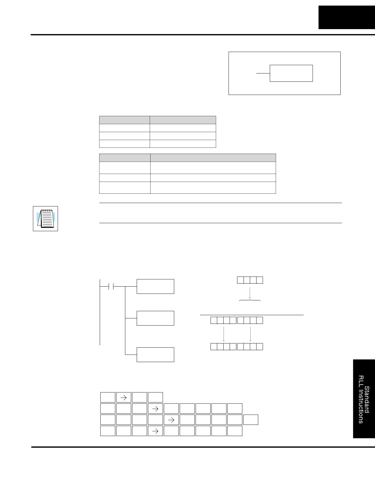
Standard RLL Instructions
5-63
Math Instructions
Multiply
Multiply is a
16 bit instruction that
(MUL)
multiplies the BCD value (Aaaa), which is
either a V memory location or a 4-digit
MUL
(max.) constant, by the BCD value in the
A aaa
lower 16 bits of the accumulator The
result can be up to 8 digits and resides in
the accumulator.
Operand Data Type
DL130 Range
A
aaa
V memory
V
All (See page 4-28)
Constant
K
0-9999
Discrete Bit Flags
Description
SP63
On when the result of the instruction causes the value in the accumulator
to be zero.
SP70
On anytime the value in the accumulator is negative.
SP75
On when a BCD instruction is executed and a NON-BCD number was
encountered.
NOTE: The status flags are only valid until another instruction that uses the same
flags is executed.
In the following example, when X1 is on, the value in V2000 will be loaded into the
accumulator using the Load instruction. The value in V2006 is multiplied by the value
in the accumulator. The value in the accumulator is copied to V2010 and V2011
using the Out Double instruction.
DirectSOFT32
V2000
X1
1
0
0
0
LD
V2000
The unused accumulator
Load the value in V2000 into
bits are set to zero
the lower 16 bits of the
accumulator
0
0
0
0
1
0
0
0
(Accumulator)
2
5
(V2006)
MUL
V2006
Acc.
0
0
0
2
5
0
0
0
The value in V2006 is
multiplied by the value in the
accumulator
0
0
0
2
5
0
0
0
OUTD
V2010
V2010
V2010
Copy the value in the
accumulator to V2010 and
V2011
Handheld Programmer Keystrokes
$
B
ENT
STR
1
L
D
C
A
A
A
SHFT
ENT
ANDST
3
2
0
0
0
M
U
L
C
A
A
G
SHFT
ENT
ORST
ISG
ANDST
2
0
0
6
GX
D
C
A
B
A
SHFT
ENT
OUT
3
2
0
1
0
DL105 PLC User Manual, 2nd Edition, Rev. A
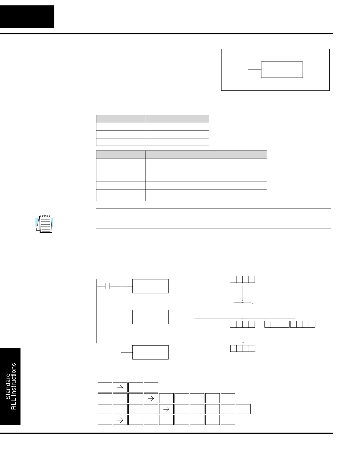
Standard RLL Instructions
5-64
Math Instructions
Divide
Divide is a 16 bit instruction that divides
(DIV)
the BCD value in the accumulator by a
BCD value (Aaaa), which is either a V
DIV
memory location or a
4-digit
(max.)
A aaa
constant. The first part of the quotient
resides in the accumulator and the
remainder resides in the first stack
location.
Operand Data Type
DL130 Range
A
aaa
V memory
V
All (See page 4-28)
Constant
K
0-9999
Discrete Bit Flags
Description
SP53
On when the value of the operand is larger than the accumulator can work
with.
SP63
On when the result of the instruction causes the value in the accumulator
to be zero.
SP70
On anytime the value in the accumulator is negative.
SP75
On when a BCD instruction is executed and a NON-BCD number was
encountered.
NOTE: The status flags are only valid until another instruction that uses the same
flags is executed.
In the following example, when X1 is on, the value in V2000 will be loaded into the
accumulator using the Load instruction. The value in the accumulator will be divided
by the value in V2006 using the Divide instruction. The value in the accumulator is
copied to V2010 using the Out instruction.
DirectSOFT32
V2000
5
0
0
0
X1
LD
V2000
Load the value in V2000 into
The unused accumulator
the lower 16 bits of the
bits are set to zero
accumulator
0
0
0
0
5
0
0
0
(Accumulator)
DIV
4
9
(V2006)
V2006
Acc.
1
0
2
0
0
0
0
0
0
0
2
The value in the
accumulator is divided by
First stack location contains
the value in V2006
the remainder
OUT
1
0
0
V2010
V2010
Copy the value in the lower
16 bits of the accumulator to
V2010
Handheld Programmer Keystrokes
$
B
ENT
STR
1
L
D
C
A
A
A
SHFT
ENT
ANDST
3
2
0
0
0
D
I
V
C
A
A
G
SHFT
ENT
3
8
AND
2
0
0
6
GX
V
C
A
B
A
SHFT
ENT
OUT
AND
2
0
1
0
DL105 PLC User Manual, 2nd Edition, Rev. A
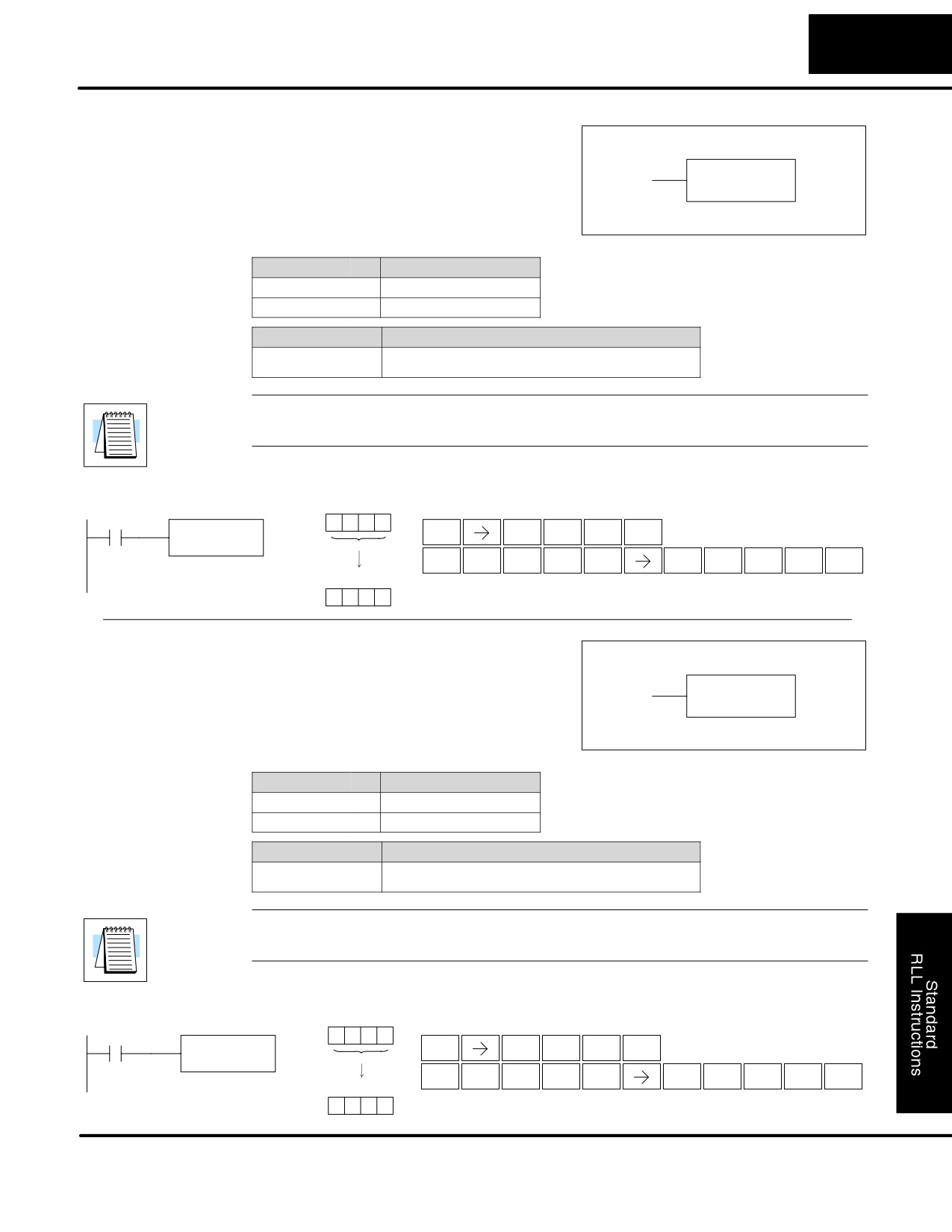
Standard RLL Instructions
5-65
Math Instructions
Increment Binary
The Increment Binary instruction
(INCB)
increments a binary value in a specified V
memory location by “1” each time the
INCB
instruction is executed.
A aaa
Operand Data Type
DL105 Range
A
aaa
V memory
V
All (See page 4-28)
Discrete Bit Flags
Description
SP63
on when the result of the instruction causes the value in the accumulator
to be zero.
NOTE: The status flags are only valid until another instruction that uses the same
flags is executed.
In the following example when C5 is on, the binary value in V2000 is increased by 1.
DirectSOFT32
V2000
Handheld Programmer Keystrokes
C5
4
A
3
C
INCB
$
C
F
SHFT
ENT
STR
2
5
V2000
I
N
C
B
C
A
A
A
SHFT
ENT
Increment the binary value
8
TMR
2
1
2
0
0
0
in the accumulator by“1”
V2000
4
A
3
D
Decrement Binary The Decrement Binary instruction
(DECB)
decrements a binary value in a specified V
memory location by “1” each time the
DECB
instruction is executed.
A aaa
Operand Data Type
DL130 Range
A
aaa
V memory
V
All (See page 4-28)
Discrete Bit Flags
Description
SP63
on when the result of the instruction causes the value in the accumulator
to be zero.
NOTE: The status flags are only valid until another instruction that uses the same
flags is executed.
In the following example when C5 is on, the value in V2000 is decreased by 1.
DirectSOFT32
V2000
Handheld Programmer Keystrokes
4
A
3
C
C5
DECB
$
C
F
SHFT
ENT
STR
2
5
V2000
SHFT
D
E
C
B
C
A
A
A
ENT
Decrement the binary value
3
4
2
1
2
0
0
0
in the accumulator by“1”
V2000
4
A
3
B
DL105 PLC User Manual, 2nd Edition, Rev. A
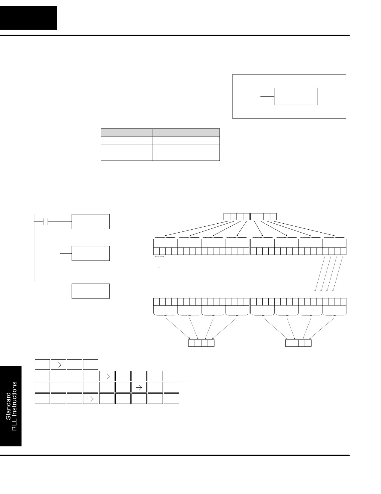
Standard RLL Instructions
5-66
Bit Operation Instructions
Bit Operation Instructions
Shift Left
Shift Left is a 32 bit instruction that shifts
(SHFL)
the bits in the accumulator a specified
number (Aaaa) of places to the left. The
SHFL
vacant positions are filled with zeros and
A aaa
the bits shifted out of the accumulator are
discarded.
Operand Data Type
DL130 Range
A
aaa
V memory
V
All (See page 4-28)
Constant
K
1-32
In the following example, when X1 is on, the value in V2000 and V2001 will be loaded
into the accumulator using the Load Double instruction. The bit pattern in the
accumulator is shifted 2 bits to the left using the Shift Left instruction. The value in the
accumulator is copied to V2010 and V2011 using the Out Double instruction.
DirectSOFT32
V2001
V2000
X1
6
7
0
5
3
1
0
1
LDD
V2000
Load the value in V2000 and
V2001 into the accumulator
31 30 29 28
27 26 25 24
23 22 21 20
19 18 17 16
15 14 13 12
11 10
9
8
7
6
5
4
3
2
1
0
SHFL
Acc.
0
1
1
0
0
1
1
1
0
0
0
0
0
1
0
1
0
0
1
1
0
0
0
1
0
0
0
0
0
0
0
1
K2
The bit pattern in the
accumulator is shifted 2 bit
S
S
S
S
positions to the left
Shifted out of the
accumulator
OUTD
V2010
31 30 29 28 27 26 25 24 23 22 21 20 19 18 17 16
15 14 13 12 11 10
9
8
7
6
5
4
3
2
1
0
Copy the value in the
Acc.
1
0
0
1
1
1
0
0
0
0
0
1
0
1
0
0
1
1
0
0
0
1
0
0
0
0
0
0
0
1
0
0
accumulator to V2010 and
V2011
9
C
1
4
C
4
0
4
V2011
V2010
Handheld Programmer Keystrokes
$
B
ENT
STR
1
L
D
D
C
A
A
A
SHFT
ENT
ANDST
3
3
2
0
0
0
SHFT
S
SHFT
H
F
L
C
ENT
RST
7
5
ANDST
2
GX
D
C
A
B
A
SHFT
ENT
OUT
3
2
0
1
0
DL105 PLC User Manual, 2nd Edition, Rev. A
Standard RLL Instructions
5-67
Bit Operation Instructions
Shift Right
Shift Right is a 32 bit instruction that shifts
(SHFR)
the bits in the accumulator a specified
number (Aaaa) of places to the right. The
SHFR
vacant positions are filled with zeros and
A aaa
the bits shifted out of the accumulator are
lost.
Operand Data Type
DL130 Range
A
aaa
V memory
V
All (See page 4-28)
Constant
K
1-32
In the following example, when X1 is on, the value in V2000 and V2001 will be loaded
into the accumulator using the Load Double instruction. The bit pattern in the
accumulator is shifted 2 bits to the right using the Shift Right instruction. The value in
the accumulator is copied to V2010 and V2011 using the Out Double instruction.
DirectSOFT32
V2001
V2000
X1
6
7
0
5
3
1
0
1
LDD
Constant
V2000
Load the value in V2000 and
V2001 into the accumulator
31 30 29 28
27 26 25 24
23 22 21 20
19 18 17 16
15 14 13 12
11 10
9
8
7
6
5
4
3
2
1
0
SHFR
Acc.
0
1
1
0
0
1
1
1
0
0
0
0
0
1
0
1
0
0
1
1
0
0
0
1
0
0
0
0
0
0
0
1
K2
The bit pattern in the
accumulator is shifted 2 bit
S
S
S
S
positions to the right
Shifted out of the
accumulator
OUTD
V2010
31 30 29 28 27 26 25 24 23 22 21 20 19 18 17 16
15 14 13 12 11 10
9
8
7
6
5
4
3
2
1
0
Copy the value in the
Acc.
0
0
0
1
1
0
0
1
1
1
0
0
0
0
0
1
0
1
0
0
1
1
0
0
0
1
0
0
0
0
0
0
accumulator to V2010 and
V2011
1
9
C
1
4
C
4
0
V2011
V2010
Handheld Programmer Keystrokes
$
B
ENT
STR
1
L
D
D
C
A
A
A
SHFT
ENT
ANDST
3
3
2
0
0
0
S
H
F
R
C
SHFT
SHFT
ENT
RST
7
5
ORN
2
GX
D
C
A
B
A
SHFT
ENT
OUT
3
2
0
1
0
DL105 PLC User Manual, 2nd Edition, Rev. A
Standard RLL Instructions
5-68
Bit Operation Instructions
Encode
The Encode instruction encodes the bit
(ENCO)
position in the accumulator having a value
of 1, and returns the appropriate binary
ENCO
representation. If the most significant bit is
set to 1 (Bit 31), the Encode instruction
would place the value HEX 1F (decimal
31) in the accumulator. If the value to be
encoded is 0000 or 0001, the instruction
will place a zero in the accumulator. If the
value to be encoded has more than one bit
position set to a “1”, the least significant “1”
will be encoded and SP53 will be set on.
Discrete Bit Flags
Description
SP53
On when the value of the operand is larger than the accumulator can work
with.
NOTE: The status flags are only valid until another instruction that uses the same
flags is executed.
In the following example, when X1 is on, The value in V2000 is loaded into the
accumulator using the Load instruction. The bit position set to a “1” in the
accumulator is encoded to the corresponding 5 bit binary value using the Encode
instruction. The value in the lower 16 bits of the accumulator is copied to V2010
using the Out instruction.
DirectSOFT32
V2000
1
0
0
0
X1
LD
V2000
Load the value in V2000 into
the lower 16 bits of the
31 30 29 28
27 26 25 24
23 22 21 20
19 18 17 16
15 14 13 12
11 10
9
8
7
6
5
4
3
2
1
0
accumulator
Acc.
0
0
0
0
0
0
0
0
0
0
0
0
0
0
0
0
0
0
0
1
0
0
0
0
0
0
0
0
0
0
0
0
Bit postion 12 is
converted
to binary
ENCO
31 30 29 28
27 26 25 24
23 22 21 20
19 18 17 16
15 14 13 12
11 10
9
8
7
6
5
4
3
2
1
0
Encode the bit position set
to “1” in the accumulator to a
Acc.
0
0
0
0
0
0
0
0
0
0
0
0
0
0
0
0
0
0
0
0
0
0
0
0
0
0
0
0
1
1
0
0
5 bit binary value
OUT
V2010
0
0
0
C
Copy the value in the lower 16 bits
of the accumulator to V2010
V2010
Binary value
for 12.
Handheld Programmer Keystrokes
$
B
ENT
STR
1
L
D
C
A
A
A
SHFT
ENT
ANDST
3
2
0
0
0
E
N
C
O
SHFT
ENT
4
TMR
2
INST#
GX
V
C
A
B
A
SHFT
ENT
OUT
AND
2
0
1
0
DL105 PLC User Manual, 2nd Edition, Rev. A
Standard RLL Instructions
5-69
Bit Operation Instructions
Decode
The Decode instruction decodes a 5 bit
(DECO)
binary value of 0-31 (0-1F HEX) in the
accumulator by setting the appropriate bit
DECO
position to a 1. If the accumulator contains
the value F (HEX), bit 15 will be set in the
accumulator. If the value to be decoded is
greater than 31, the number is divided by
32 until the value is less than 32 and then
the value is decoded.
In the following example when X1 is on, the value formed by discrete locations
X10-X14 is loaded into the accumulator using the Load Formatted instruction. The
five bit binary pattern in the accumulator is decoded by setting the corresponding bit
position to a “1” using the Decode instruction.
DirectSOFT32
X14
X13
X12
X11
X10
X1
OFF
ON
OFF
ON
ON
LDF
X10
K5
Load the value in
represented by discrete
locations X10-X14 into the
31 30 29 28
27 26 25 24
23 22 21 20
19 18 17 16
15 14 13 12
11 10
9
8
7
6
5
4
3
2
1
0
accumulator
Acc.
0
0
0
0
0
0
0
0
0
0
0
0
0
0
0
0
0
0
0
0
0
0
0
0
0
0
0
0
1
0
1
1
The binary vlaue
is converted to
bit position 11.
DECO
31 30 29 28
27 26 25 24
23 22 21 20
19 18 17 16
15 14 13 12
11 10
9
8
7
6
5
4
3
2
1
0
Decode the five bit binary
Acc.
0
0
0
0
0
0
0
0
0
0
0
0
0
0
0
0
0
0
0
0
1
0
0
0
0
0
0
0
0
0
0
0
pattern in the accumulator
and set the corresponding
bit position to a “1”
Handheld Programmer Keystrokes
$
B
ENT
STR
1
L
D
F
B
A
F
SHFT
ENT
ANDST
3
5
1
0
5
D
E
C
O
SHFT
ENT
3
4
2
INST#
DL105 PLC User Manual, 2nd Edition, Rev. A
Standard RLL Instructions
5-70
Number Conversion Instructions
Number Conversion Instructions (Accumulator)
Binary
The Binary instruction converts a BCD
(BIN)
value in the accumulator to the equivalent
binary value. The result resides in the
BIN
accumulator.
In the following example, when X1 is on, the value in V2000 and V2001 is loaded into
the accumulator using the Load Double instruction. The BCD value in the
accumulator is converted to the binary (HEX) equivalent using the BIN instruction.
The binary value in the accumulator is copied to V2010 and V2011 using the Out
Double instruction. (The handheld programmer will display the binary value in
V2010 and V2011 as a HEX value.)
DirectSOFT32
V2001
V2000
X1
0
0
0
2
8
5
2
9
LDD
V2000
Load the value in V2000 and
V2001 into the accumulator
8
4
2
1
8
4
2
1
8
4
2
1
8
4
2
1
8
4
2
1
8
4
2
1
8
4
2
1
8
4
2
1
Acc.
0
0
0
0
0
0
0
0
0
0
0
0
0
0
1
0
1
0
0
0
0
1
0
1
0
0
1
0
1
0
0
1
BCD Value
28529 = 16384 + 8192 + 2048 + 1024 + 512 + 256 + 64 + 32 + 16 + 1
Binary Equivalent Value
BIN
31
30
29
28
27
26
25 24
23 22 21 20
19 18 17 16
15 14 13 12
11 10
9
8
7
6
5
4
3
2
1
0
Convert the BCD value in
Acc.
0
0
0
0
0
0
0
0
0
0
0
0
0
0
0
0
0
1
1
0
1
1
1
1
0
1
1
1
0
0
0
1
the accumulator to the
binary equivalent value
2
1
5
2
1
6
3
1
8
4
2
1
5
2
1
6
3
1
8
4
2
1
5
2
1
6
3
1
8
4
2
1
1
0
3
6
3
7
3
6
3
1
0
0
2
6
3
5
2
6
1
0
0
0
1
5
2
4
2
6
4
7
6
8
4
1
5
7
8
9
9
4
4
2
1
5
7
3
9
9
4
2
2
6
8
7
3
8
4
2
0
5
7
8
4
7
8
2
1
0
3
6
8
2
6
8
4
4
7
7
3
1
8
4
7
6
3
1
5
8
4
7
6
8
4
4
4
0
5
7
8
4
2
0
0
5
7
8
4
2
8
1
9
4
7
6
3
1
8
4
2
6
3
8
1
5
2
4
2
6
6
2
2
6
8
4
4
8
OUTD
V2010
0
0
0
0
6
F
7
1
The binary (HEX) value
Copy the binary value in the
copied to V2010
accumulator to V2010 and V2011
V2011
V2010
Handheld Programmer Keystrokes
$
B
ENT
STR
1
L
D
D
C
A
A
A
SHFT
ENT
ANDST
3
3
2
0
0
0
B
I
N
SHFT
ENT
1
8
TMR
GX
D
C
A
B
A
SHFT
ENT
OUT
3
2
0
1
0
DL105 PLC User Manual, 2nd Edition, Rev. A
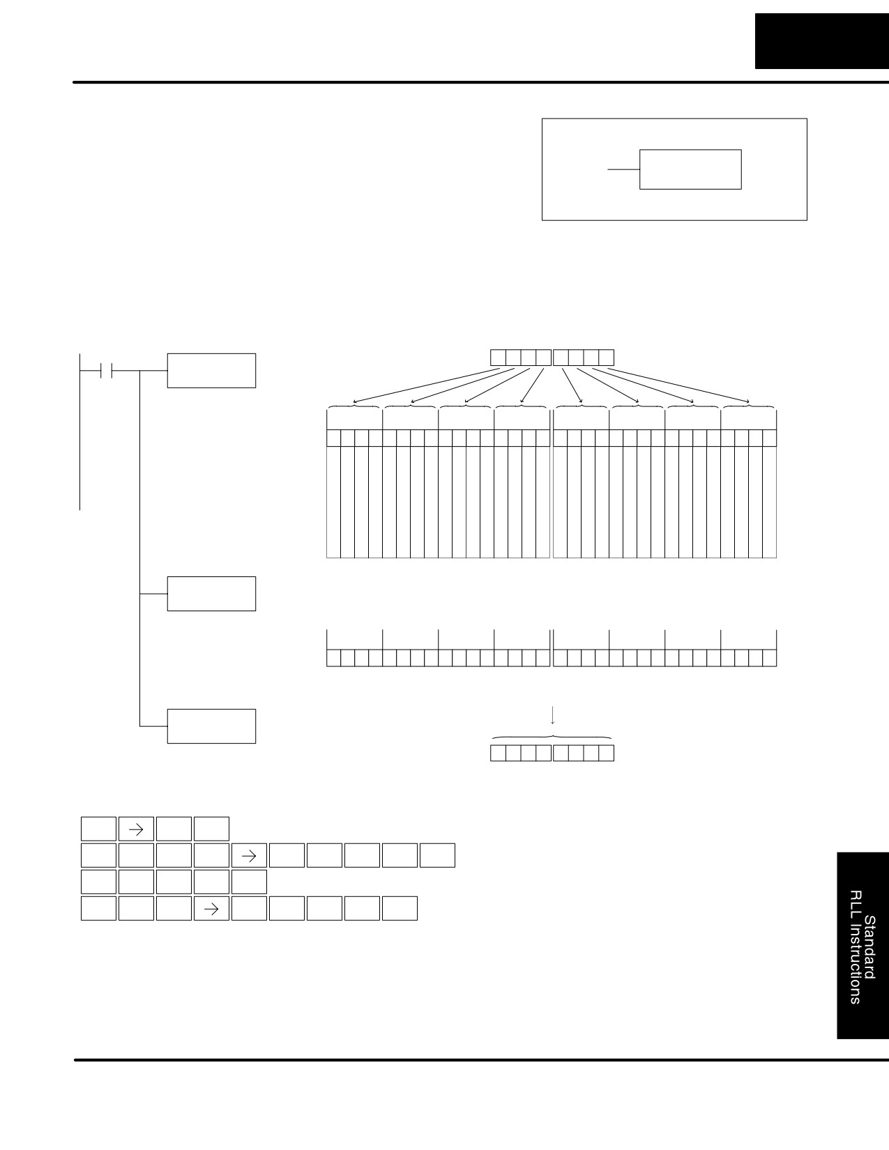
Standard RLL Instructions
5-71
Number Conversion Instructions
Binary Coded
The Binary Coded Decimal instruction
Decimal
converts a binary value in the accumulator
(BCD)
to the equivalent BCD value. The result
BCD
resides in the accumulator.
In the following example, when X1 is on, the binary (HEX) value in V2000 and V2001
is loaded into the accumulator using the Load Double instruction. The binary value in
the accumulator is converted to the BCD equivalent value using the BCD instruction.
The BCD value in the accumulator is copied to V2010 and V2011 using the Out
Double instruction.
DirectSOFT32
V2001
V2000
X1
0
0
0
0
6
F
7
1
LDD
Binary Value
V2000
Load the value in V2000 and
V2001 into the accumulator
31 30 29 28
27 26 25 24
23 22 21 20
19 18 17 16
15 14 13 12
11 10
9
8
7
6
5
4
3
2
1
0
Acc.
0
0
0
0
0
0
0
0
0
0
0
0
0
0
0
0
0
1
1
0
1
1
1
1
0
1
1
1
0
0
0
1
2
1
5
2
1
6
3
1
8
4
2
1
5
2
1
6
3
1
8
4
2
1
5
2
1
6
3
1
8
4
2
1
1
0
3
6
3
7
3
6
3
1
0
0
2
6
3
5
2
6
1
0
0
0
1
5
2
4
2
6
4
7
6
8
4
1
5
7
8
9
9
4
4
2
1
5
7
3
9
9
4
2
2
6
8
7
3
8
4
2
0
5
7
8
4
7
8
2
1
0
3
6
8
2
6
8
4
4
7
7
3
1
8
4
7
6
3
1
5
8
4
7
6
8
4
4
4
0
5
7
8
4
2
0
0
5
7
8
4
2
8
1
9
4
7
6
3
1
8
4
2
6
3
8
1
5
2
4
2
6
6
2
2
6
8
4
4
8
BCD
16384 + 8192 + 2048 + 1024 + 512 + 256 + 64 + 32 + 16 + 1 = 28529
Convert the binary value in
BCD Equivalent Value
the accumulator to the BCD
equivalent value
8
4
2
1
8
4
2
1
8
4
2
1
8
4
2
1
8
4
2
1
8
4
2
1
8
4
2
1
8
4
2
1
Acc.
0
0
0
0
0
0
0
0
0
0
0
0
0
0
1
0
1
0
0
0
0
1
0
1
0
0
1
0
1
0
0
1
OUTD
V2010
Copy the BCD value in the
0
0
0
2
8
5
2
9
The BCD value
accumulator to V2010 and V2011
copied to
V2011
V2010
V2010 and V2011
Handheld Programmer Keystrokes
$
B
ENT
STR
1
L
D
D
C
A
A
A
SHFT
ENT
ANDST
3
3
2
0
0
0
B
C
D
SHFT
ENT
1
2
3
GX
D
C
A
B
A
SHFT
ENT
OUT
3
2
0
1
0
DL105 PLC User Manual, 2nd Edition, Rev. A
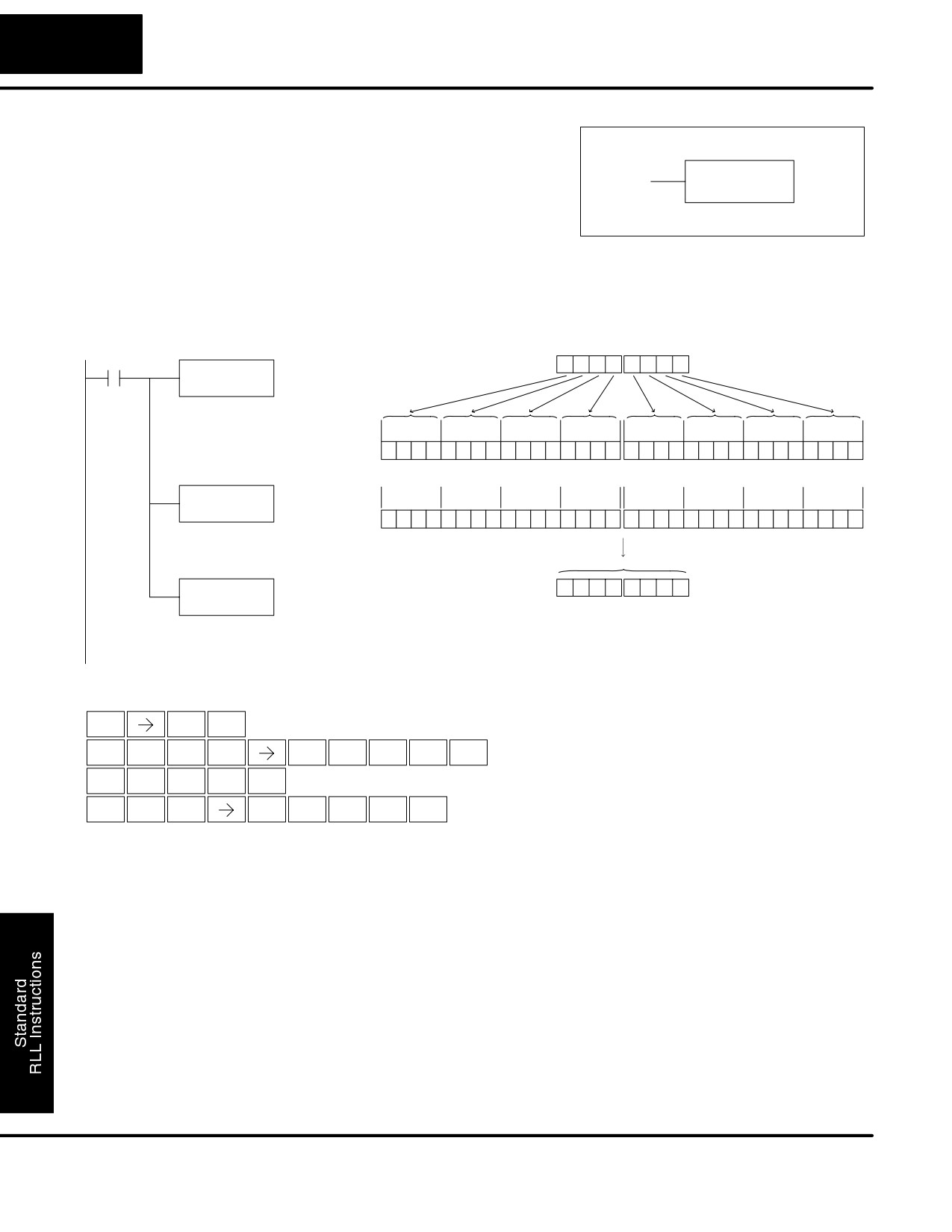
Standard RLL Instructions
5-72
Number Conversion Instructions
Invert
The Invert instruction inverts or takes the
(INV)
one’s complement of the 32 bit value in the
accumulator. The result resides in the
INV
accumulator.
In the following example, when X1 is on, the value in V2000 and V2001 will be loaded
into the accumulator using the Load Double instruction. The value in the
accumulator is inverted using the Invert instruction. The value in the accumulator is
copied to V2010 and V2011 using the Out Double instruction.
DirectSOFT32
V2001
V2000
X1
0
4
0
5
0
2
5
0
LDD
V2000
Load the value in V2000 and
V2001 into the accumulator
31
30
29 28
27
26 25
24
23
22
21
20
19 18 17
16
15
14 13 12
11
10
9
8
7
6
5
4
3
2
1
0
Acc.
0
0
0
0
0
1
0
0
0
0
0
0
0
1
0
1
0
0
0
0
0
0
1
0
0
1
0
1
0
0
0
0
INV
31
30
29 28
27
26 25
24
23
22
21
20
19 18 17
16
15
14 13 12
11
10
9
8
7
6
5
4
3
2
1
0
Acc.
1
1
1
1
1
0
1
1
1
1
1
1
1
0
1
0
1
1
1
1
1
1
0
1
1
0
1
0
1
1
1
1
Invert the binary bit pattern
in the accumulator
OUTD
F
B
F
A
F
D
A
F
V2010
V2011
V2010
Copy the value in the
accumulator to V2010 and
V2011
Handheld Programmer Keystrokes
$
B
ENT
STR
1
SHFT
L
D
D
C
A
A
A
ENT
ANDST
3
3
2
0
0
0
I
N
V
SHFT
ENT
8
TMR
AND
GX
D
C
A
B
A
SHFT
ENT
OUT
3
2
0
1
0
DL105 PLC User Manual, 2nd Edition, Rev. A
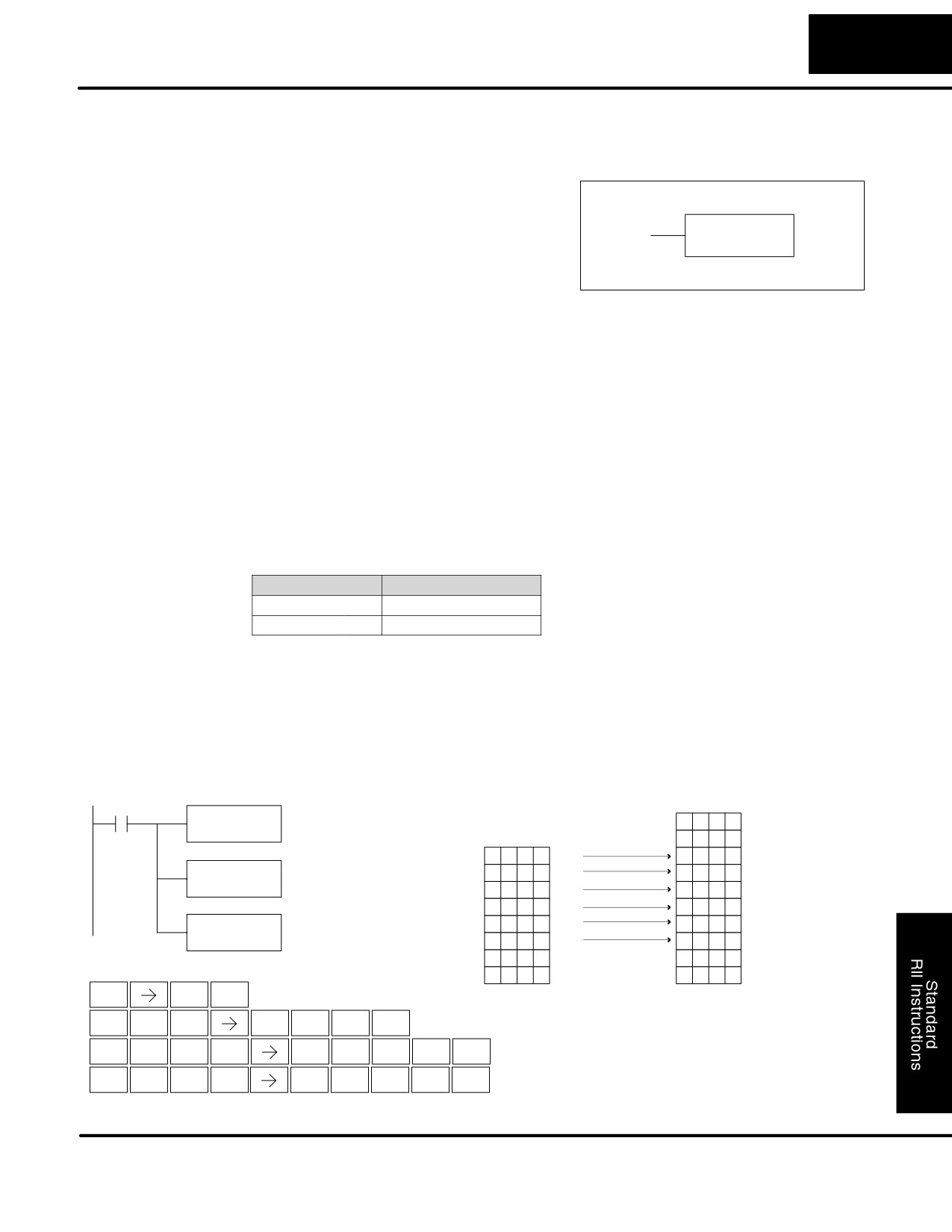
Standard RLL Instructions
5-73
Table Instructions
Table Instructions
Move
The Move instruction moves the values
(MOV)
from a V memory table to another
V memory table the same length. The
MOV
function parameters are loaded into the
V aaa
first level of the accumulator stack and the
accumulator
by
two
additional
instructions. Listed below are the steps
necessary to program the Move function.
S Step 1:— Load the number of V memory locations to be moved into the
first level of the accumulator stack. This parameter is a HEX value (K40
max, 100 octal).
S Step 2:— Load the starting V memory location for the locations to be
moved into the accumulator. This parameter is a HEX value.
S Step 3:— Insert the MOVE instruction which specifies starting V
memory location (Vaaa) for the destination table.
Helpful Hint: — For parameters that require HEX values when referencing memory
locations, the LDA instruction can be used to convert an octal address to the HEX
equivalent and load the value into the accumulator.
Operand Data Type
DL130 Range
aaa
V memory
V
All (See page 4-28)
In the following example, when X1 is on, the constant value (K6) is loaded into the
accumulator using the Load instruction. This value specifies the length of the table
and is placed in the first stack location after the Load Address instruction is
executed. The octal address 2000 (V2000), the starting location for the source table
is loaded into the accumulator. The destination table location (V2030) is specified in
the Move instruction.
DirectSOFT32
S
S
X1
Load the constant value 6
LD
(HEX) into the lower 16 bits
S
X
X
X
X
V2026
K6
of the accumulator
S
X
X
X
X
V2027
0
1
2
3
V2000
0
1
2
3
V2030
Convert octal 2000 to HEX
LDA
0
5
0
0
0
5
0
0
400 and load the value into
V2001
V2031
O 2000
the accumulator
9
9
9
9
V2002
9
9
9
9
V2032
3
0
7
4
V2003
3
0
7
4
V2033
Copy the specified table
MOV
8
9
8
9
V2004
8
9
8
9
V2034
locations to a table
V2030
beginning at location V2030
1
0
1
0
V2005
1
0
1
0
V2035
X
X
X
X
V2006
X
X
X
X
V2036
Handheld Programmer Keystrokes
X
X
X
X
V2007
X
X
X
X
V2037
$
B
ENT
S
S
STR
1
S
S
L
D
K
G
SHFT
SHFT
ENT
ANDST
3
JMP
6
SHFT
L
D
A
C
A
A
A
ENT
ANDST
3
0
2
0
0
0
M
O
V
C
A
D
A
SHFT
ENT
ORST
INST#
AND
2
0
3
0
DL105 PLC User Manual, 2nd Edition, Rev. A
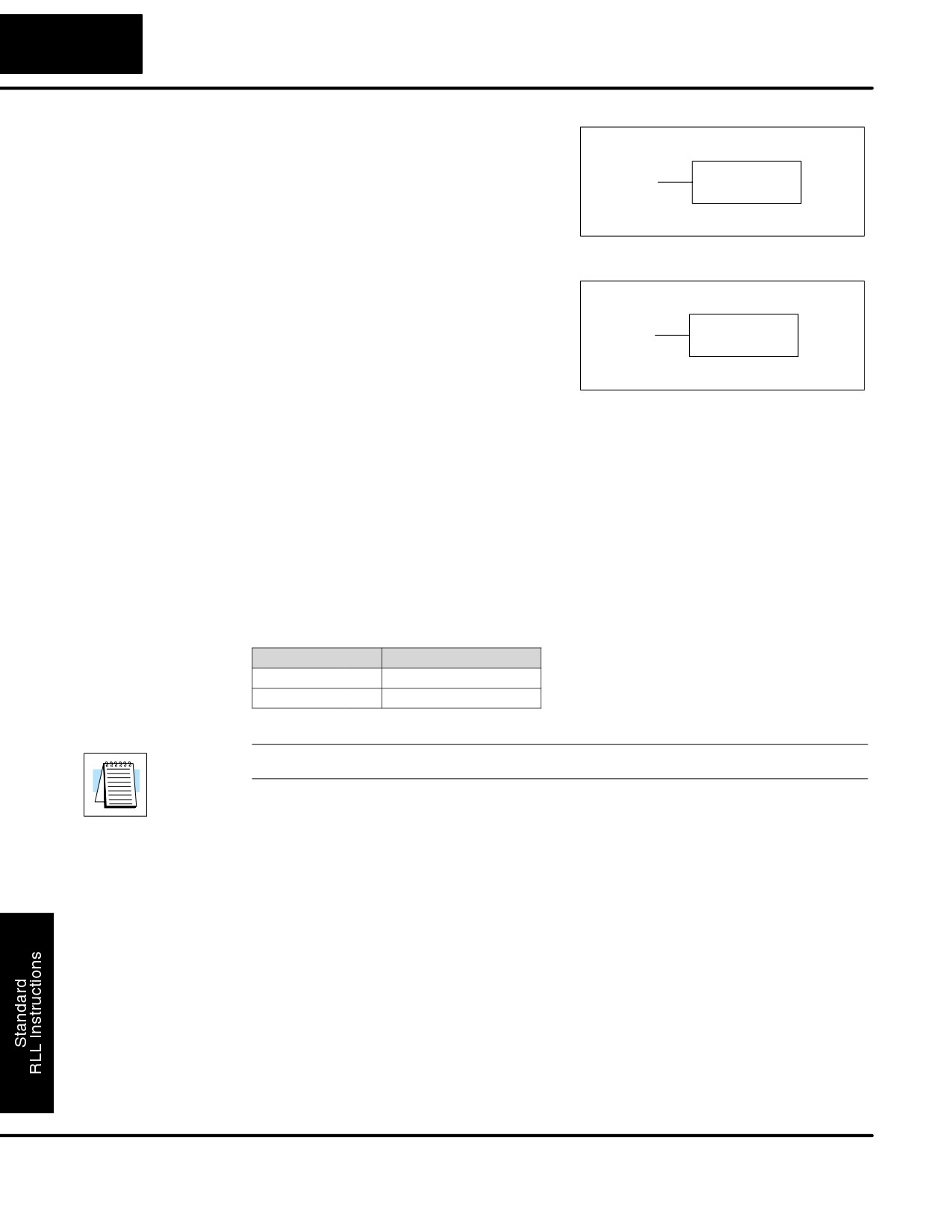
Standard RLL Instructions
5-74
Table Instructions
Move Memory
The Move Memory Cartridge instruction is
Cartridge /
used to copy data between V memory and
Load Label
program ladder memory. The Load Label
MOVMC
instruction is only used with the MOVMC
V aaa
(MOVMC), (LDLBL)
instruction when copying data from
program ladder memory to V memory.
To copy data between V memory and
program ladder memory, the function
parameters are loaded into the first two
levels of the accumulator stack and the
accumulator
by
two
additional
LDLBL
K aaa
instructions. Listed below are the steps
necessary to program the Move Memory
Cartridge and Load Label functions.
S Step 1:— Load the number of words to be copied into the second level
of the accumulator stack.
S Step 2:— Load the offset for the data label area in ladder memory and
the beginning of the V memory block into the first level of the stack.
S Step 3:— Load the source data label (LDLBL Kaaa) into the
accumulator when copying data from ladder memory to V memory. Load
the source address (LDA Oaaa) into the accumulator when copying data
from V-memory to ladder memory. This is the source location of the
value. Source addresses in V-memory must be entered in HEX.
S Step 4:— Insert the MOVMC instruction which specifies destination
V-memory (Vaaa), or data label (Kaaa). This is the copy destination.
Operand Data Type
DL130 Range
A
aaa
V memory
V
All (See page 4-28)
NOTE:See Appendix E for an explanation of the DL105 memory system.
DL105 PLC User Manual, 2nd Edition, Rev. A
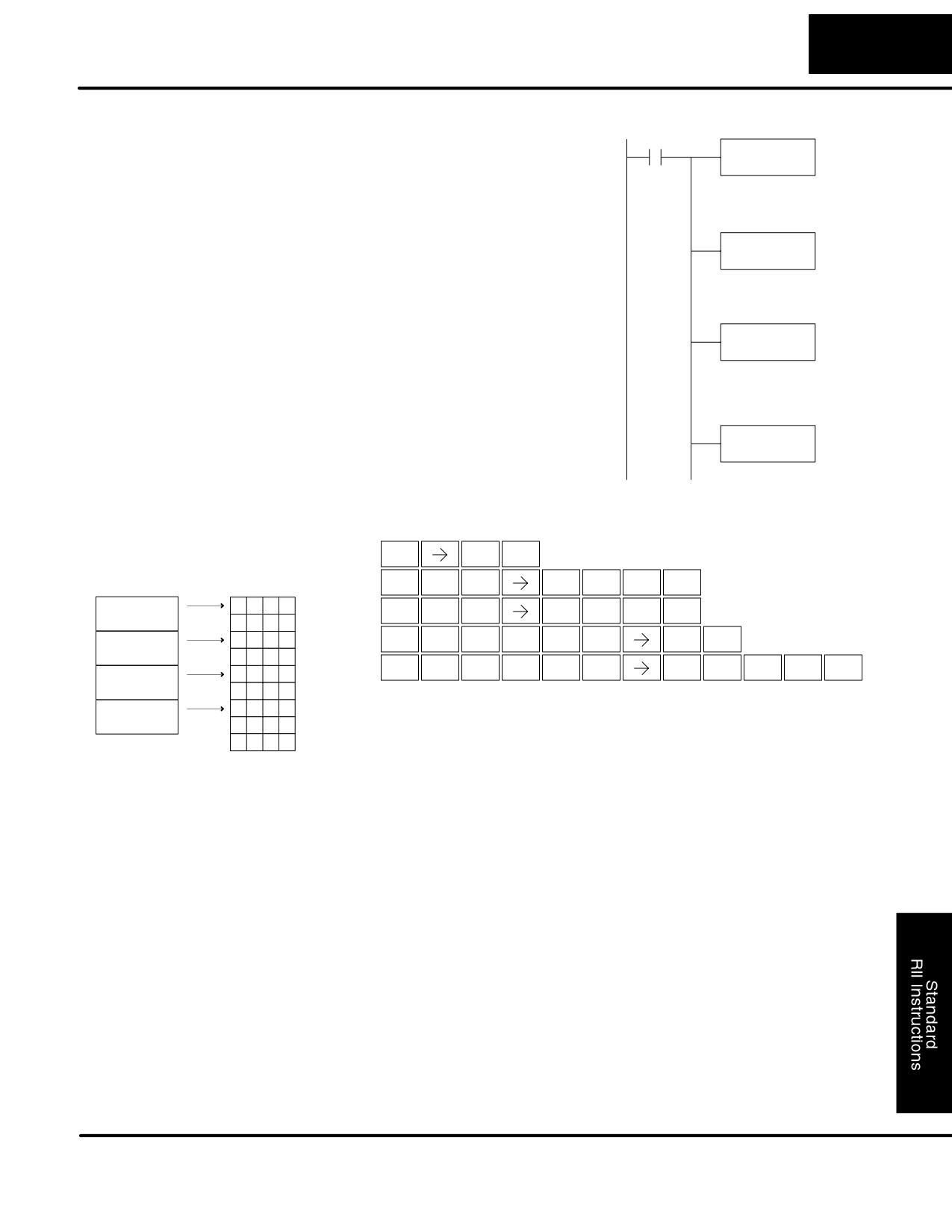
Standard RLL Instructions
5-75
Table Instructions
DirectSOFT32
In the example to the right, data is copied
Copy Data From a
X1
LD
from a Data Label Area to V memory.
Data Label Area to
K4
V Memory
When X1 is on, the constant value (K4) is
Load the value 4 into the
loaded into the accumulator using the
accumulator specifying the
number of locations to be
Load instruction. This value specifies the
copied.
length of the table and is placed in the
LD
second stack location after the next Load
K0
and Load Label (LDLBL) instructions are
Load the value 0 into the
executed. The constant value (K0) is
accumulator specifying the
offset for source and
loaded into the accumulator, specifying
destination locations
the offset for the source and destination
LDLBL
data. It is placed in the first stack location
K1
after the LDLBL instruction is executed.
Load the value 1 into the
The source address where data is being
accumulator specifying the
Data Label Area K1 as the
copied from is loaded into the
starting address of the data
to be copied.
accumulator
using
the
LDLBL
instruction. The MOVMC instruction
MOVMC
V2000
specifies the destination starting location
and executes the copying of data from
V2000 is the destination
starting address for the data
the Data Label Area to V memory.
to be copied.
Data Label Area
Handheld Programmer Keystrokes
Programmed
After the END
$
B
ENT
Instruction
STR
1
S
L
D
K
E
S
SHFT
SHFT
ENT
DLBL K1
ANDST
3
JMP
4
N C O N
1
2
3
4
V2000
L
D
K
A
SHFT
SHFT
ENT
ANDST
3
JMP
0
K
1
2
3
4
L
D
L
B
L
B
N C O N
4
5
3
2
V2001
SHFT
ENT
ANDST
3
ANDST
1
ANDST
1
K
4
5
3
2
M
O
V
M
C
C
A
A
A
SHFT
ENT
N C O N
6
1
5
1
V2002
ORST
INST#
AND
ORST
2
2
0
0
0
K
6
1
5
1
N
C O N
8
8
4
5
V2003
K
8
8
4
5
X
X
X
X
V2004
S
S
DL105 PLC User Manual, 2nd Edition, Rev. A
Standard RLL Instructions
5-76
CPU Control Instructions
CPU Control Instructions
No Operation
The No Operation is an empty
(not
(NOP)
programmed) memory location.
NOP
DirectSOFT32
Handheld Programmer Keystrokes
N
O
P
SHFT
ENT
TMR
INST#
CV
NOP
End
The End instruction marks the termination
(END)
point of the normal program scan. An End
instruction is required at the end of the
END
main program body. If the End instruction
is omitted an error will occur and the CPU
will not enter the Run Mode. Data labels,
subroutines and interrupt routines are
placed after the End instruction. The End
instruction is not conditional; therefore, no
input contact is allowed.
DirectSOFT32
Handheld Programmer Keystrokes
E
N
D
SHFT
ENT
4
TMR
3
END
Stop
The Stop instruction changes the
(STOP)
operational mode of the CPU from Run to
Program (Stop) mode. This instruction is
STOP
typically used to stop PLC operation in an
error condition.
In the following example, when C0 turns on, the CPU will stop operation and switch
to the program mode.
DirectSOFT32
Handheld Programmer Keystrokes
$
C
A
C0
SHFT
ENT
STR
2
0
STOP
S
T
O
P
SHFT
SHFT
ENT
RST
MLR
INST#
CV
DL105 PLC User Manual, 2nd Edition, Rev. A
Standard RLL Instructions
5-77
Program Control Instructions
Program Control Instructions
Master Line Set
The Master Line Set instruction allows the
(MLS)
program to control sections of ladder logic
K aaa
by forming a new power rail controlled by
MLS
the main left power rail. The main left rail is
always master line 0. When a MLS K1
instruction is used, a new power rail is
created at level 1. Master Line Sets and
Master Line Resets can be used to nest
power rails up to seven levels deep.
Operand Data Type
DL130 Range
aaa
Constant
K
1-7
Master Line Reset The Master Line Reset instruction marks
(MLR)
the end of control for the corresponding
K aaa
MLS instruction. The MLR reference is one
MLR
less than the corresponding MLS.
Operand Data Type
DL130 Range
aaa
Constant
K
0-6
Understanding
The Master Line Set (MLS) and Master Line Reset (MLR) instructions allow you to
Master Control
quickly enable (or disable) sections of the RLL program. This provides program
Relays
control flexibility. The following example shows how the MLS and MLR instructions
operate by creating a sub power rail for control logic.
DirectSOFT32
X0
K1
When contact X0 is on, logic under the first MLS
MLS
will be executed.
X1
Y7
OUT
X2
K2
When contact X0 and X2 are ON, logic
MLS
under the second MLS will be executed.
X3
Y10
OUT
K1
MLR
The MLR instructions note the end of the Master
K0
Control area.
MLR
X10
Y11
OUT
DL105 PLC User Manual, 2nd Edition, Rev. A
Standard RLL Instructions
5-78
Program Control Instructions
In the following MLS/MLR example logic between the first MLS K1 (A) and MLR K0
MLS/MLR Example
(B) will function only if input X0 is on. The logic between the MLS K2 (C) and MLR K1
(D) will function only if input X10 and X0 is on. The last rung is not controlled by either
of the MLS coils.
DirectSOFT32
Handheld Programmer Keystrokes
X0
K1
A
$
A
ENT
MLS
STR
0
Y
B
ENT
X1
C0
MLS
1
OUT
$
B
ENT
STR
1
X2
GX
C
A
C1
SHFT
ENT
OUT
2
0
OUT
$
C
ENT
STR
2
X3
Y0
GX
C
B
SHFT
ENT
OUT
OUT
2
1
$
D
ENT
X10
STR
3
K2
C
GX
A
MLS
ENT
OUT
0
$
B
A
X5
Y1
ENT
STR
1
0
OUT
Y
C
ENT
MLS
2
X4
Y2
$
F
ENT
STR
5
OUT
GX
B
ENT
OUT
1
K1
D
$
E
MLR
ENT
STR
4
GX
C
X5
C2
ENT
OUT
2
OUT
T
B
ENT
MLR
1
X6
Y3
$
F
ENT
STR
5
OUT
GX
C
C
SHFT
ENT
OUT
2
2
K0
B
$
G
MLR
ENT
STR
6
GX
D
X7
ENT
Y4
OUT
3
OUT
T
A
ENT
MLR
0
$
H
ENT
STR
7
GX
E
C
ENT
OUT
4
2
DL105 PLC User Manual, 2nd Edition, Rev. A
Standard RLL Instructions
5-79
Interrupt Instructions
Interrupt Instructions
Interrupt
The Interrupt instruction allows a section of
(INT)
ladder logic to be placed below the main
body of the program and executed only
INT
O
when needed. High-Speed I/O Modes 10,
20, and 40 can generate an interrupt. With
Mode 40, you may select an external
interrupt
(input X0), or a time-based
interrupt (5-999 mS).
Typically, interrupts are used in an application when a fast response to an input is
needed or a program section must execute faster than the normal CPU scan. The
interrupt label and all associated logic must be placed after the End statement in the
program. When an interrupt occurs, the CPU will complete execution of the current
instruction it is processing in ladder logic, then execute the interrupt routine. After
interrupt routine execution, the ladder program resumes from the point at which it
was interrupted.
See Chapter 3, the section on Mode 40 (Interrupt) Operation for more details on
interrupt configuration. In the DL105, only one interrupt is available.
Operand Data Type
DL130 Range
Constant
O
0
Interrupt Return
An Interrupt Return is normally executed as
(IRT)
the last instruction in the interrupt routine. It
returns the CPU to the point in the main
IRT
program from which it was called. The
Interrupt Return is a stand-alone
instruction (no input contact on the rung).
Enable Interrupts The Enable Interrupt instruction is placed in
(ENI)
the main ladder program (before the End
instruction), enabling the interrupt. The
ENI
interrupt remains enabled until the program
executes a Disable Interrupt instruction.
Disable Interrupts A Disable Interrupt instruction in the main
(DISI)
body of the application program (before
the End instruction) will disable the
DISI
interupt
(either extenal or timed). The
interrupt remains disabled until the
program executes an Enable Interrupt
instruction.
DL105 PLC User Manual, 2nd Edition, Rev. A
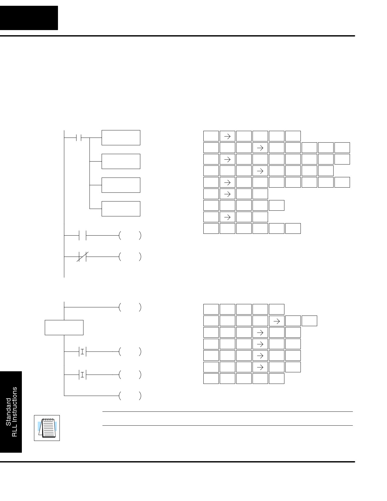
Standard RLL Instructions
5-80
Interrupt Instructions
In the following example, we do some initialization on the first scan, using the
External Interrupt
first-scan contact SP0. The interrupt feature is the HSIO Mode 40. Then we
Program Example
configure X0 as the external interrupt by writing to its configuration register, V7634.
See Chapter 3, Mode 40 Operation for more details.
During program execution, when X2 is on the interrupt is enabled. When X2 is off the
interrupt will be disabled. When an interrupt signal (X0) occurs the CPU will jump to
the interrupt label INT O 0. The application ladder logic in the interrupt routine will be
performed. The CPU will return to the main body of the program after the IRT
instruction is executed.
DirectSOFT32
Handheld Programmer Keystrokes
SP0
Load the constant value
LD
$
SP
A
(K40) into the lower 16 bits
SHFT
ENT
K40
STR
STRN
0
of the accumulator
L
D
K
E
A
SHFT
SHFT
ENT
ANDST
3
JMP
4
0
OUT
Copy the value in the lower
GX
V
H
G
D
D
SHFT
ENT
16 bits of the accumulator to
OUT
AND
7
6
3
3
V7633
V7633
L
D
K
E
SHFT
SHFT
ENT
ANDST
3
JMP
4
Load the constant value (K4)
GX
V
H
G
D
E
LD
SHFT
ENT
into the lower 16 bits of the
OUT
AND
7
6
3
4
K4
accumulator
$
C
ENT
STR
2
OUT
Copy the value in the lower
SHFT
E
N
I
ENT
16 bits of the accumulator to
4
TMR
8
V7634
V7634
SP
C
ENT
STRN
2
X2
D
I
S
I
SHFT
ENT
3
8
RST
8
ENI
X2
DISI
S
S
S
S
S
END
E
N
D
SHFT
ENT
4
TMR
3
I
N
T
A
SHFT
ENT
INT
O 0
8
TMR
MLR
0
$
I
B
SHFT
ENT
STR
8
1
X1
X
I
F
Y5
SHFT
ENT
SET
8
5
SETI
$
I
D
SHFT
ENT
STR
8
3
X3
X
I
H
Y7
SHFT
ENT
SET
8
7
SETI
I
R
T
SHFT
ENT
8
ORN
MLR
IRT
NOTE: Only one interrupt is available in the DL105 and it must be Int 0.
DL105 PLC User Manual, 2nd Edition, Rev. A
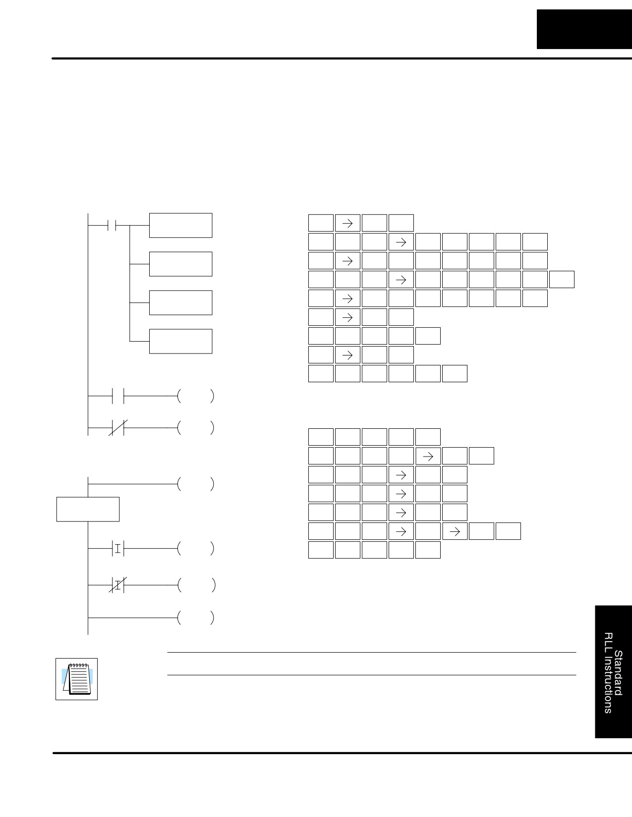
Standard RLL Instructions
5-81
Interrupt Instructions
In the following example, we do some initialization on the first scan, using the
Timed Interrupt
first-scan contact SP0. The interrupt feature is the HSIO Mode 40. Then we
Program Example
configure the HSIO timer as a 10 mS interrupt by writing K104 to the configuration
register for X0 (V7634). See Chapter 3, Mode 40 Operation for more details.
When X4 turns on, the interrupt will be enabled. When X4 turns off, the interrupt will
be disabled. Every 10 mS the CPU will jump to the interrupt label INT O 0. The
application ladder logic in the interrupt routine will be performed. If X3 is not on
Y0-Y7 will be reset to off and then the CPU will return to the main body of the
program.
DirectSOFT32
Handheld Programmer Keystrokes
X1
Load the constant value
LD
$
B
(K40) into the lower 16 bits
ENT
K40
STR
1
of the accumulator
L
D
K
E
A
SHFT
SHFT
ENT
ANDST
3
JMP
4
0
OUT
Copy the value in the lower
GX
V
H
G
D
D
SHFT
ENT
16 bits of the accumulator to
OUT
AND
7
6
3
3
V7633
V7633
L
D
K
B
A
E
SHFT
SHFT
ENT
ANDST
3
JMP
1
0
4
Load the constant value
GX
V
H
G
D
E
LD
SHFT
ENT
(K10) into the lower 16 bits
OUT
AND
7
6
3
4
K104
of the accumulator
$
E
ENT
STR
4
Copy the value in the lower
E
N
I
OUT
SHFT
ENT
16 bits of the accumulator to
4
TMR
8
V7634
V7634
SP
E
ENT
STRN
4
D
I
S
I
SHFT
ENT
3
8
RST
8
X4
ENI
S
S
S
X4
DISI
E
N
D
SHFT
ENT
4
TMR
3
S
I
N
T
A
S
SHFT
ENT
8
TMR
MLR
0
S
$
I
C
SHFT
ENT
STR
8
2
END
X
I
F
SHFT
ENT
SET
8
5
INT
O0
SP
I
D
SHFT
ENT
STRN
8
3
X
SHFT
I
A
H
ENT
X2
Y5
SET
8
0
7
SETI
I
R
T
SHFT
ENT
8
ORN
MLR
X3
Y0
Y7
RSTI
IRT
NOTE: Only one interrupt is available in the DL105 and it must be Int 0.
DL105 PLC User Manual, 2nd Edition, Rev. A
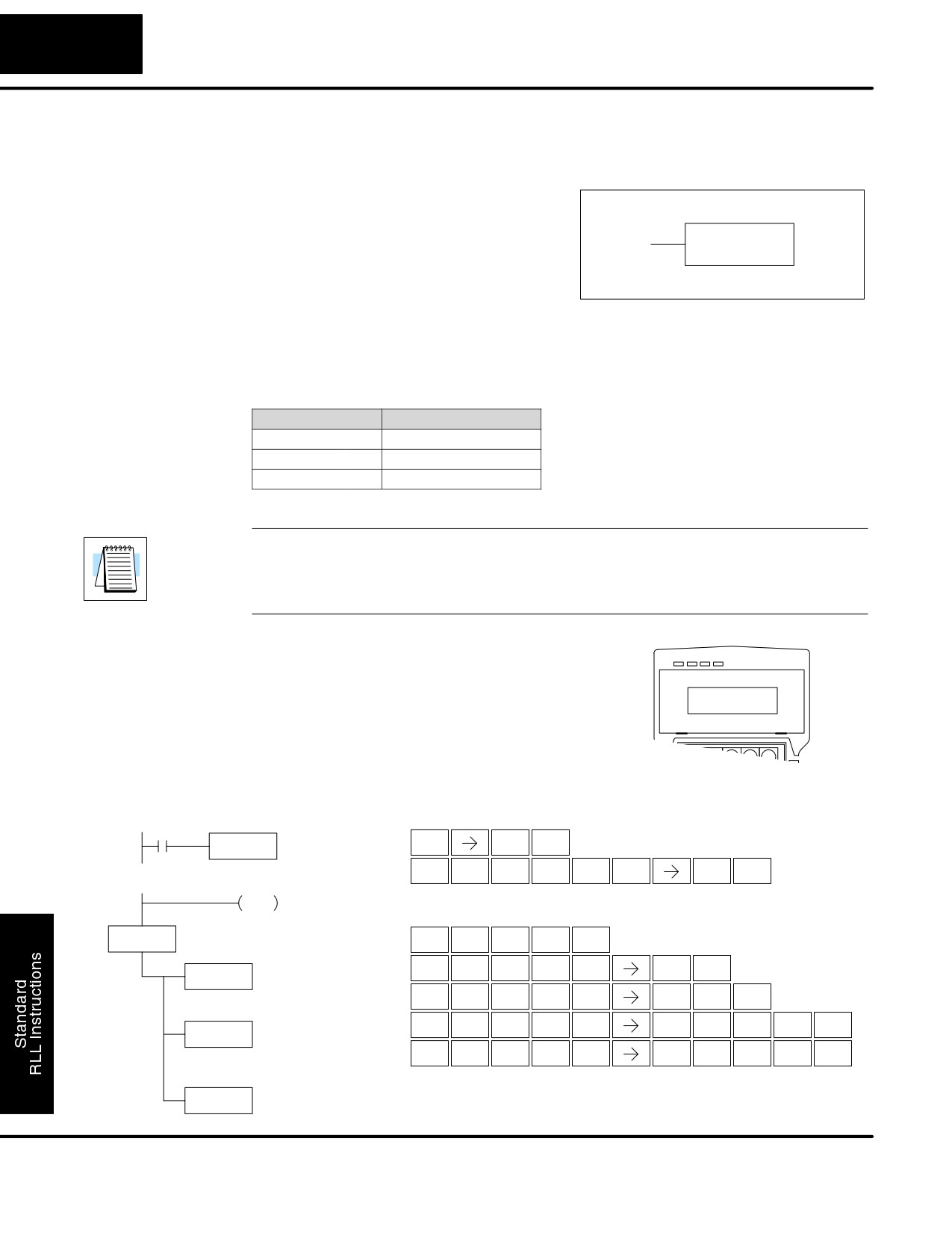
Standard RLL Instructions
5-82
Message Instructions
Message Instructions
Fault
The Fault instruction is used to display a
(FAULT)
message on the handheld programmer or
in the DirectSOFT32 status bar. The
FAULT
message has a maximum of 23 characters
A aaa
and can be either V memory data,
numerical constant data or ASCII text.
To display the value in a V memory location, specify the V memory location in the
instruction. To display the data in ACON (ASCII constant) or NCON (Numerical
constant) instructions, specify the constant (K) value for the corresponding data
label area.
Operand Data Type
DL130 Range
A
aaa
V memory
V
All (See page 4-28)
Constant
K
1-FFFF
NOTE: The FAULT instruction takes a considerable amount of time to execute. This
is because the FAULT parameters are stored in EEPROM. Be sure to consider the
instructions execution times (shown in Appendix C) if you are attempting to use the
FAULT instructions in applications that require faster than normal execution cycles.
Fault Example
In the following example when X1 is on,
the message SW 146 will display on the
handheld programmer. The NCONs use
SW 146
the HEX ASCII equivalent of the text to
be displayed. (The HEX ASCII for a blank
is 20, a 1 is 31, 4 is 34 ...)
DirectSOFT32
Handheld Programmer Keystrokes
S
S
X1
FAULT
$
B
ENT
K1
STR
1
F
A
U
L
T
B
S
SHFT
ENT
5
0
ISG
ANDST
MLR
1
S
S
END
S
DLBL
E
N
D
K1
SHFT
ENT
4
TMR
3
D
L
B
L
B
ACON
SHFT
ENT
3
ANDST
1
ANDST
1
A SW
A
C
O
N
S
W
SHFT
ENT
0
2
INST#
TMR
RST
ANDN
N
C
O
N
C
A
D
B
NCON
SHFT
ENT
TMR
2
INST#
TMR
2
0
3
1
K 2031
N
C
O
N
D
E
D
G
SHFT
ENT
TMR
2
INST#
TMR
3
4
3
6
NCON
K 3436
DL105 PLC User Manual, 2nd Edition, Rev. A
Standard RLL Instructions
5-83
Message Instructions
Data Label
The Data Label instruction marks the
(DLBL)
beginning of an ASCII / numeric data area.
DLBLs are programmed after the End
DLBL
K aaa
statement. A maximum of
32 DLBL
instructions can be used in a program.
Multiple NCONs and ACONs can be used
in a DLBL area.
Operand Data Type
DL130 Range
aaa
Constant
K
1-FFFF
ASCII Constant
The ASCII Constant instruction is used
(ACON)
with the DLBL instruction to store ASCII
text for use with other instructions. Two
ACON
ASCII characters can be stored in an
A aaa
ACON instruction. If only one character is
stored in a ACON a leading space will be
inserted.
Operand Data Type
DL130 Range
aaa
ASCII
A
0-9 A-Z
Numerical
The Numerical Constant instruction is
Constant
used with the DLBL instruction to store the
(NCON)
HEX ASCII equivalent of numerical data
NCON
for use with other instructions. Two digits
K aaa
can be stored in an NCON instruction.
Operand Data Type
DL130 Range
aaa
Constant
K
0-FFFF
DL105 PLC User Manual, 2nd Edition, Rev. A
Standard RLL Instructions
5-84
Message Instructions
In the following example, an ACON and two NCON instructions are used within a
Data Label
DLBL instruction to build a text message. See the FAULT instruction for information
Example
on displaying messages. The DV-1000 Manual also has information on displaying
messages.
DirectSOFT32
S
S
S
END
DLBL
K1
ACON
A SW
NCON
K 2031
NCON
K 3436
Handheld Programmer Keystrokes
S
S
E
N
D
SHFT
ENT
4
TMR
3
D
L
B
L
B
SHFT
ENT
3
ANDST
1
ANDST
1
A
C
O
N
S
W
SHFT
ENT
0
2
INST#
TMR
RST
ANDN
N
C
O
N
C
A
D
B
SHFT
ENT
TMR
2
INST#
TMR
2
0
3
1
N
C
O
N
D
E
D
G
SHFT
ENT
TMR
2
INST#
TMR
3
4
3
6
DL105 PLC User Manual, 2nd Edition, Rev. A
6
Drum Instruction
Programming
In This Chapter
Ċ Introduction
Ċ Step Transitions
Ċ Overview of Drum Operation
Ċ Drum Control Techniques
Ċ Drum Instruction
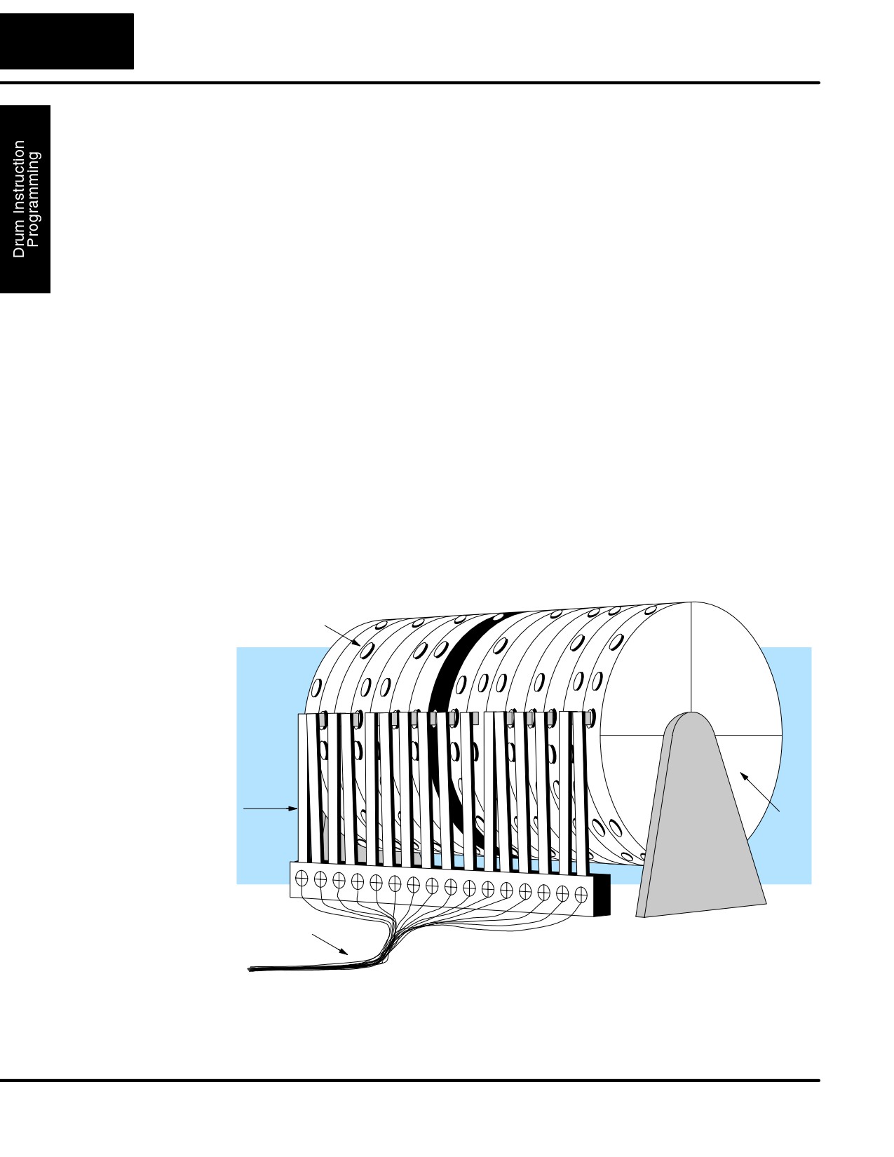
6-2
Drum Instruction Programming
Introduction
Purpose
The Event Drum (EDRUM) instruction in the F1-130 CPU electronically simulates
an electro-mechanical drum sequencer. The instruction offers enhancements to the
basic principle, which we describe first.
Drum instructions are best suited for repetitive processes that consist of a finite
Drum Terminology
number of steps. They can do the work of many rungs of ladder logic with elegant
simplicity. Therefore, drums can save a lot of programming and debugging time.
We introduce some terminology associated with the drum instruction by describing
the original mechanical drum shown below. The mechanical drum generally has
pegs on its curved surface. The pegs are populated in a particular pattern,
representing a set of desired actions for machine control. A motor or solenoid rotates
the drum a precise amount at specific times. During rotation, stationary wipers sense
the presence of pegs (present = on, absent = off). This interaction makes or breaks
electrical contact with the wipers, creating electrical outputs from the drum. The
outputs are wired to devices on a machine for On/Off control.
Drums usually have a finite number of positions within one rotation, called steps.
Each step represents some process step. At powerup, the drum resets to a
particular step. The drum rotates from one step to the next based on a timer, or on
some external event. During special conditions, a machine operator can manually
increment the drum step using a jog control on the drum’s drive mechanism. The
contact closure of each wiper generates a unique on/off pattern called a sequence,
designed for controlling a specific machine. Because the drum is circular, it
automatically repeats the sequence once per rotation. Applications vary greatly, and
a particular drum may rotate once per second, or as slowly as once per week.
Pegs
Wipers
Drum
Outputs
Electronic drums provide the benefits of mechanical drums and more. For example,
they have a preset feature that is impossible for mechanical drums: The preset
function lets you move from the present step directly to any other step on command!
DL105 PLC User Manual, 2nd Edition, Rev. A