DL105 Micro PLC. User Manual (2003) - page 4
3-50
High-speed Input and Pulse Output Features
Pulse Catch
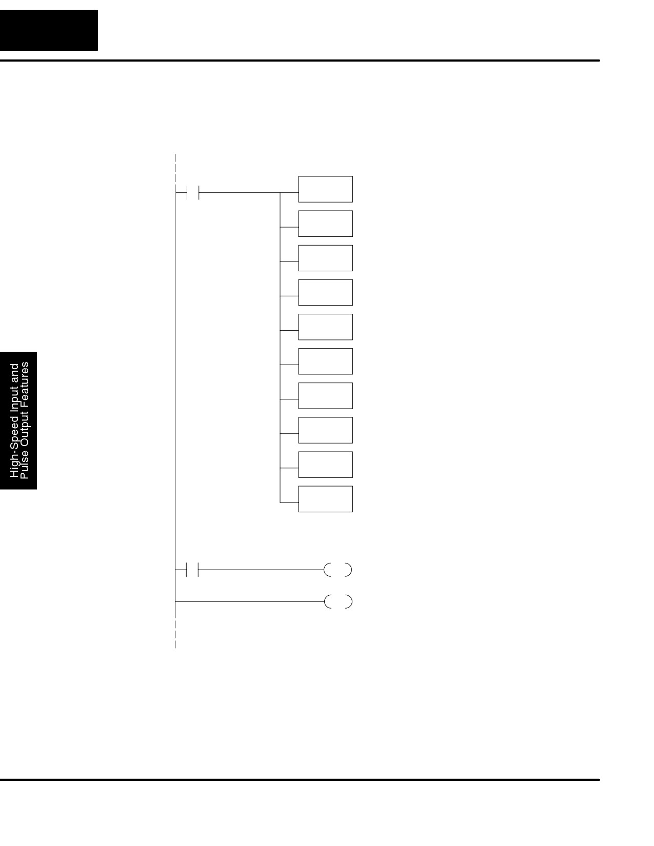
The following program selects Mode 50, then programs the pulse catch code for X0.
Program Example
Inputs X1, X2, and X3 are all configured as filtered inputs with 10, 30, and 50 mS time
constants respectively. The program is otherwise generic, and may be adapted to
your application.
DirectSOFT32
SP0
Load constant K50 into the accumulator. This
LD
selects Mode 50 as the HSIO mode.
K50
Mode 50
Output this constant to V7633, the location of the
OUT
HSIO Mode select register.
V7633
Load the constant K5 which is required to configure X0
Pulse Catch
LD
as the pulse catch input.
K5
Output this constant to V7634, configuring the pulse
OUT
catch option for X0.
V7634
Load the constant K1006 which is required to select
Filtered Inputs
LD
filtered inputs with a 10 mS filter time constant.
K1006
Output this constant to V7635, configuring X1.
OUT
V7635
Load the constant K3006 which is required to select
LD
filtered inputs with a 30 mS filter time constant.
K3006
Output this constant to V7636, configuring X2.
OUT
V7636
Load the constant K5006 which is required to select
LD
filtered inputs with a 50 mS filter time constant.
K5006
Output this constant to V7637, configuring X3.
OUT
V7637
Main Program
SP100
Y0
SET
Use the pulse catch input to set output Y0 on. This will
work even for a very short pulse on X0.
END
END coil marks the end of the main program..
DL105 PLC User Manual, 2nd Edition, Rev. A
3-51
High-Speed Input and Pulse Output Features
Mode 60: Discrete Inputs with Filter
Purpose
The last mode we will discuss for the HSIO circuit is Mode 60, Discrete Inputs with
Filter. The purpose of this mode is to allow the input circuit to reject narrow pulses
and accept wide ones, as viewed from the ladder program. This is useful in
especially noisy environments or other applications where pulse width is important.
In all other modes in this chapter, X0 to X3 usually support the mode functions as
special inputs. Only spare inputs operate as filtered inputs by default. Now in Mode
60, all four inputs X0 through X3 function only as discrete filtered inputs.
Functional Block
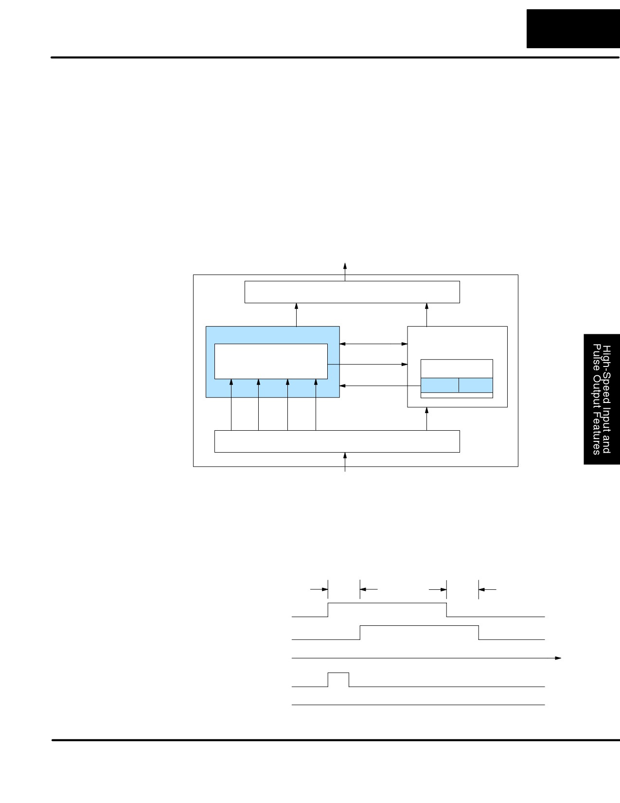
Refer to the block diagram below. When the lower byte of HSIO Mode register V7633
Diagram
contains a BCD “60”, the input filter in the HSIO circuit is enabled. Each input X0
through X3 has its own filter time constant. The filter circuit assigns the outputs of the
filters as logical references X0 through X3.
DL105
Output Circuit
PLC
Y0, Y1
Y2 - Y7
HSIO
CPU
I/O data
FILTERS
X0-X3
VĆmemory
Mode Select
V7633
xx60
X0
X1
X2
X3
X4- X11
Input Circuit
Input Filter
Signal pulses at inputs X0 - X3 are filtered by using a delay time. In the figure below,
the input pulse on the top line is longer than the filter time. The resultant logical input
Timing Parameters
to ladder is phase-shifted (delayed) by the filter time on both rising and falling edges.
In the bottom waveforms, the physical input pulse width is smaller than the filter time.
In this case, the logical input to the ladder program remains in the OFF state (input
pulse was filtered out).
Filter Time
Filter Time
Physical Input
X0
Logical Input
X0
Time
Physical Input
X0
Logical Input
X0
DL105 PLC User Manual, 2nd Edition, Rev. A
3-52
High-speed Input and Pulse Output Features
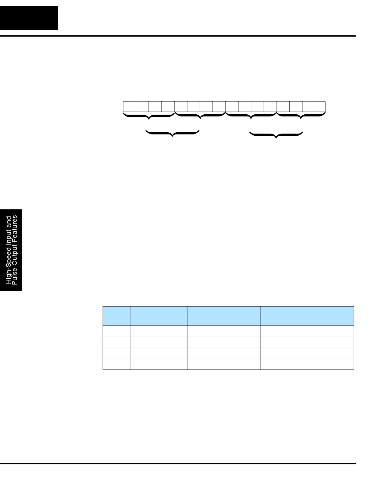
Recall that V7633 is the HSIO Mode Select register. Refer to the diagram below. Use
Setup for Mode 60
BCD 60 in the lower byte to select High-Speed Counter Mode. Use BCD 00 or 20 in
the upper byte as required. Combine the two bytes into a data word “xx60”, for writing
to V7633.
Memory Location V7633
Bits
15
14
13
12
11
10
9
8
7
6
5
4
3
2
1
0
0
0
1
0
0
0
0
0
0
1
1
0
0
0
0
0
2
0
6
0
Miscellaneous Setup (BCD)
HSIO Mode Setup (BCD)
00 = Power Up in Previous Mode
20 = Power Up in Run Mode Always
60 = Discrete Filtered Inputs
Choose the most convenient method of programming V7633 from the following:
S Include load and out instructions in your ladder program
S DirectSOFT32’s memory editor
S Use the Handheld Programmer D2-HPP
We recommend using the first method above so that the HSIO setup becomes an
integral part of your application program. An example program later in this section
shows how to to this.
X Input
The configurable discrete input options for Discrete Filtered Inputs Mode are listed
Configuration
in the table below. The filter time constant (delay) is programmable from 10 to 99 mS.
The code for this selection occupies the upper byte of the configuration register in
BCD. We combine this number with the required “06” in the lower byte to get “xx06”,
where xx = 10 to 99. Input X0, X1, X2, and X3 can only be filtered inputs. Each input
has its own configuration register and filter time constant.
Input
Configuration
Function
Hex Code
Register
Required
X0
V7634
Filtered Input
xx06 (xx = filter delay time)
X1
V7635
Filtered Input
xx06 (xx = filter delay time)
X2
V7636
Filtered Input
xx06 (xx = filter delay time)
X3
V7637
Filtered Input
xx06 (xx = filter delay time)
DL105 PLC User Manual, 2nd Edition, Rev. A
3-53
High-Speed Input and Pulse Output Features
Filtered Inputs
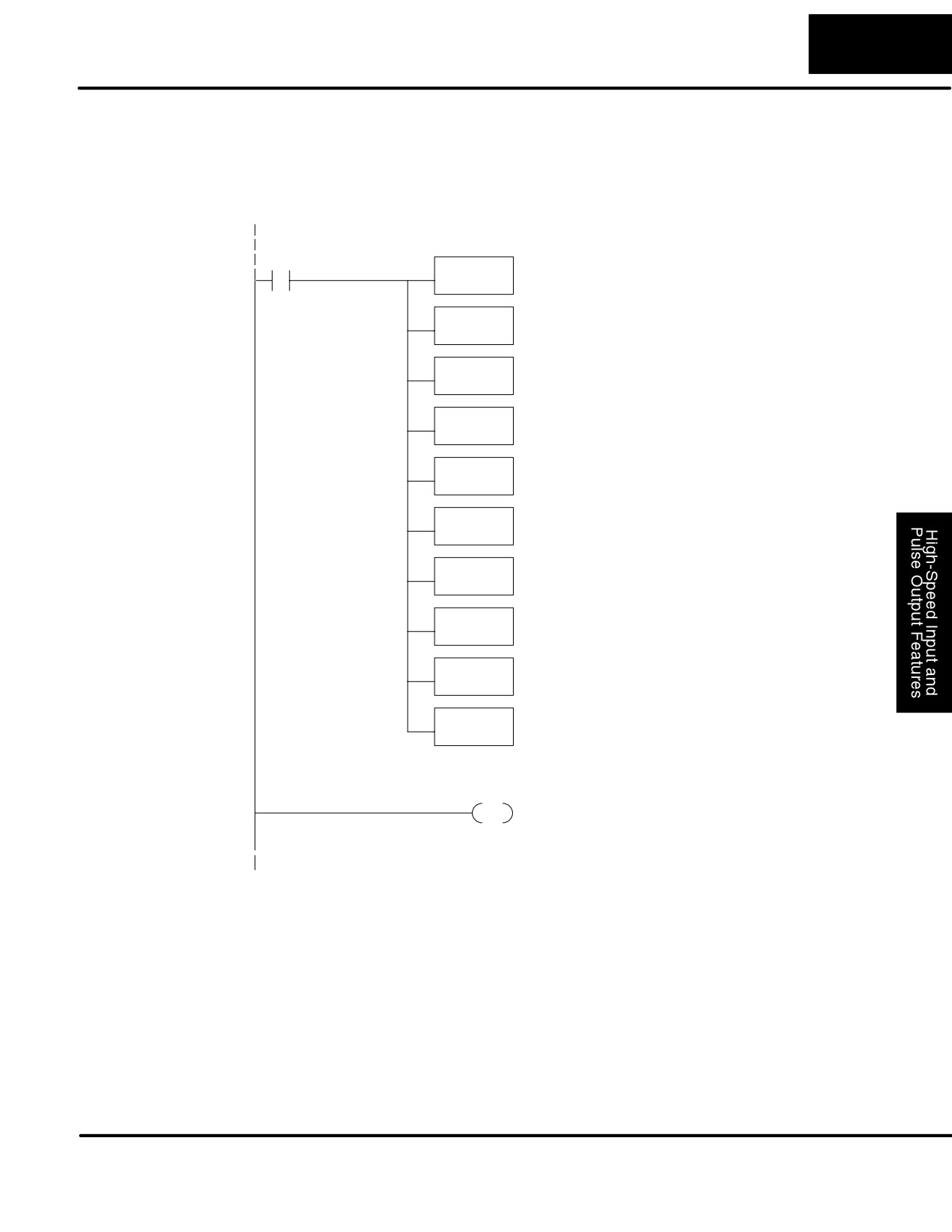
The following program selects Mode 60, then programs the filter delay time
Program Example
constants for inputs X0, X1, X2, and X3. Each filter time constant is different, for
illustration purposes. The program is otherwise generic, and may be adapted to your
application.
DirectSOFT32
SP0
Load constant K60 into the accumulator. This
LD
selects Mode 60 as the HSIO mode.
K60
Mode 60
Output the constant to V7633, the location of the
OUT
HSIO Mode select register.
V7633
Load the constant K1006 which is required to configure
Filtered Inputs
LD
filtered inputs with a time constant of 10 mS.
K1006
Output this constant to V7634, configuring X0.
OUT
V7634
Load the constant K2006 which is required to select
LD
filtered inputs with a 20 mS filter time constant.
K2006
Output this constant to V7635, configuring X1.
OUT
V7635
Load the constant K5006 which is required to select
LD
filtered inputs with a 50 mS filter time constant.
K5006
Output this constant to V7636, configuring X2.
OUT
V7636
Load the constant K9906 which is required to select
LD
filtered inputs with a 99 mS filter time constant.
K9906
Output this constant to V7637, configuring X3.
OUT
V7637
Main Program
Insert Main Program rungs here for your application.
END
END coil marks the end of the main program..
DL105 PLC User Manual, 2nd Edition, Rev. A
4
CPU Specifications
and Operation
In This Chapter
Ċ Introduction
Ċ CPU Specifications
Ċ CPU Hardware Setup
Ċ CPU Operation
Ċ Program Mode Operation
Ċ Run Mode Operation
Ċ I/O Response Time
Ċ CPU Scan Time Considerations
Ċ PLC Numbering Systems
Ċ Memory Map
Ċ DL105 System VĆMemory
Ċ X Input Bit Map
Ċ Y Output Bit Map
Ċ Control Relay Bit Map
Ċ Stage Control / Status Bit Map
Ċ Timer Status Bit Map
Ċ Counter Status Bit Map
4-2
CPU Specifications and Operation
Introduction
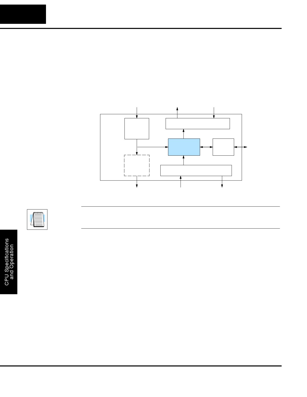
The Central Processing Unit (CPU) is the heart of the Micro PLC. Almost all PLC
operations are controlled by the CPU, so it is important that it is set up correctly. This
chapter provides the information needed to understand:
S Steps required to set up the CPU
S Operation of ladder program, organization of Variable Memory
Power Input
8 Discrete Outputs
Commons
DL105
PLC
Main
Output Circuit
Power
Supply
To Programming
Comm.
Device, or
CPU
Port
Operator
Interface
Auxiliary
+24VDC
Supply
Input Circuit
+24VDC Out
10 Discrete Inputs
Commons
(AC-powered versions only)
NOTE: The High-Speed I/O function (HSIO) consists of dedicated but configurable
hardware in the DL105. It is not considered part of the CPU, because it does not
execute the ladder program. For more on HSIO operation, see Chapter 3.
DL105
The DL105 Micro PLC which has 2.4K words of memory comprised of 2.0K of ladder
CPU Features
memory and 384 words of V-memory (data registers). Program storage is in the
FLASH memory which is a part of the CPU board in the PLC. In addition, there is
RAM with the CPU which will store system parameters, V-memory, and other data
which is not in the application program. The RAM is backed up by a
“super-capacitor”, storing the data for several days in the event of a power outage.
The capacitor automatically charges during powered operation of the PLC.
The DL105 supports fixed I/O which includes ten discrete input points and eight
output points. No provision for expansion beyond these eighteen I/O points are
available in the F1-130 model PLCs.
Over 90 different instructions are available for program development as well as
extensive internal diagnostics that can be monitored from the application program or
from an operator interface. Chapter 5 provides a detailed description of the
instructions.
The DL105 provides one built-in RS232C communication port, so you can easily
connect a handheld programmer or a personal computer without needing any
additional hardware.
DL105 PLC User Manual, 2nd Edition, Rev. A
4-3
CPU Specifications and Operation
CPU Specifications
Feature
DL105
Total Program memory (words)
2.4K
Ladder memory (words)
2048
Total V-memory (words) (See Appendix E)
384
User V-memory (words)
256
Non-volatile V Memory (words)
128
Contact execution (boolean)
3.3 mS
Typical scan (boolean)
4 - 6 mS
RLL Ladder style Programming
Yes
RLL and RLLPLUS Programming
Yes
Run Time Edits
Yes
Variable / fixed scan
Variable
Handheld programmer
Yes
DirectSOFT32 programming for Windows
Yes
Built-in communication ports (RS232C)
Yes
EEPROM or FLASH
Standard on CPU
Local Discrete I/O points available
18
Local Analog input / output channels maximum
None
High-Speed I/O (quad., pulse out, interrupt, pulse catch, etc.)
Yes
I/O Point Density
10 inputs, 8 outputs
Number of instructions available (see Chapter 5 for details)
91
Control relays
256
Special relays (system defined)
112
Stages in RLLPLUS
256
Timers
64
Counters
64
Immediate I/O
Yes
Interrupt input (external / timed)
Yes
Subroutines
No
For/Next Loops
No
Math
Integer
Drum Sequencer Instruction
Yes
Time of Day Clock/Calendar
No
Internal diagnostics
Yes
Password security
Yes
System error log
No
User error log
No
Battery backup
No (uses super-cap.)
DL105 PLC User Manual, 2nd Edition, Rev. A
4-4
CPU Specifications and Operation
CPU Hardware Setup
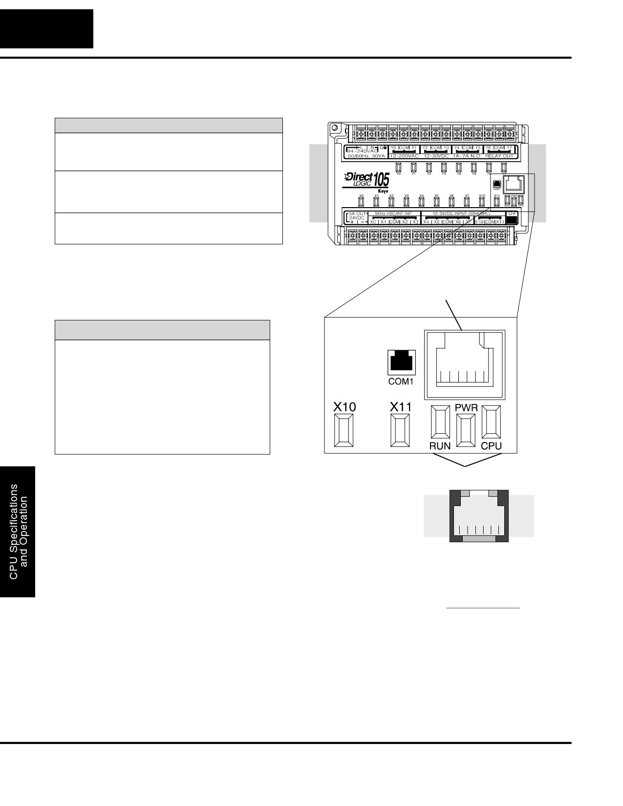
CPU Status Indicators
RUN ON CPU is in RUN mode
OFF CPU is in Program mode
CPU ON CPU internal diagnostics has
detected an error.
OFF CPU is OK.
PWR ON CPU power good
OFF CPU power failure
Communications
Port
Communication Port
Com 1 Connects to HPP, DirectSOFT32,
operator interfaces, etc.
6 5 43
2
1
6-pin, RS232C
9600 Baud
Odd parity
Station address fixed (1)
8 data bits
1 start, 1 stop bit
Asynchronous, Half-duplex, DTE
K sequence protocol
CPU Status Indicators
Communication
Cables are available that allow you to
Port Pinout
quickly and easily connect a Handheld
Diagrams
Programmer or a personal computer to
6543
2
1
the DL105 PLCs. However, if you need to
build your own cables, use the pinout
Phone Jack
diagrams shown. The DL105 PLCs
Connector
require an RJ-12 phone plug to fit the
built-in jacks.
Port Pinouts
The Micro PLC has one built-in RS232C
Pin Signal Definition
communication port. The port is generally
used for programming either with the
1
0 V
Handheld Programmer or DirectSOFT32,
2
5 V
and has a fixed station address of 1. The
3
RS232C Data in
baud rate is fixed at 9600 baud. This port
4
RS232C Data out
supports the K-sequence protocol, which
5
5 V
is a proprietary protocol.
6
0 V
NOTE: The 5V pins are rated at 200mA
maximum, primarilly for use with some
operator interface units.
DL105 PLC User Manual, 2nd Edition, Rev. A
4-5
CPU Specifications and Operation
Connecting the
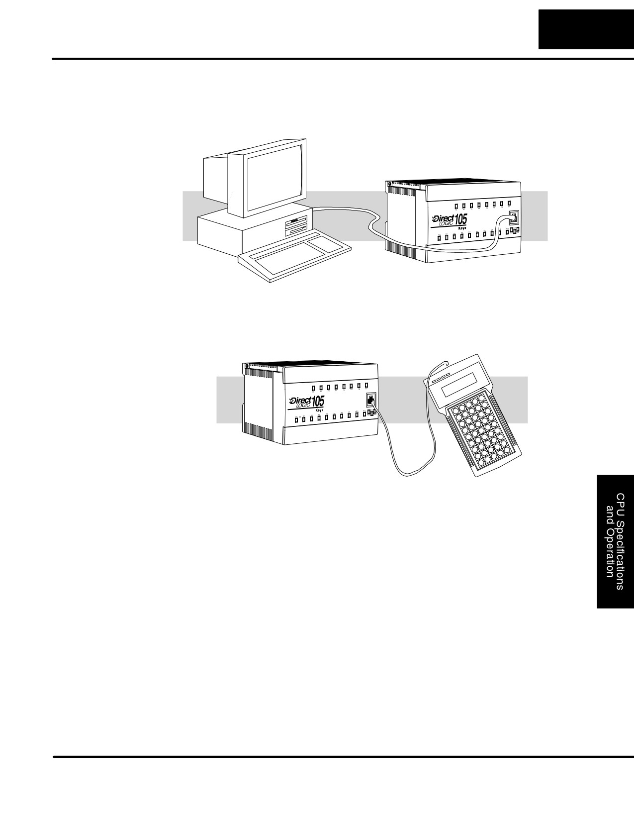
If you’re using a Personal Computer with the DirectSOFT32 programming package,
Programming
you can connect the computer to the DL105’s programming port. For an engineering
Devices
office environment (typical during program development), this is the preferred
method of programming.
Use cable part no.
D2-DSCBL
The Handheld programmer is connected to the CPU with a handheld programmer
cable. This device is ideal for maintaining existing installations or making small
program changes. The handheld programmer is shipped with a cable, which is
approximately 6.5 feet (200 cm) long.
For replacement
cable, use part no.
DV-1000CBL
CPU Setup
Even if you have years of experience using PLCs, there are a few things you need to
Information
do before you can start entering programs. This section includes some basic things,
such as changing the CPU mode, but it also includes some things that you may
never have to use. Here’s a brief list of the items that are discussed.
S Using Auxiliary Functions
S Selecting and Changing the CPU Modes
S Clearing the program (and other memory areas)
S How to initialize system memory
S Setting retentive memory ranges
The following paragraphs provide the setup information necessary to get the CPU
ready for programming. They include setup instructions for either type of
programming device you are using. The D2-HPP Handheld Programmer Manual
provides the Handheld keystrokes required to perform all of these operations. The
DirectSOFT32 Manual provides a description of the menus and keystrokes
required to perform the setup procedures via DirectSOFT32.
DL105 PLC User Manual, 2nd Edition, Rev. A
4-6
CPU Specifications and Operation
CPU Modes
There are two possible operating modes available with DL105 Micro PLCs.
S RUN — executes program and updates I/O points.
S PROGRAM — allows program changes. The CPU halts execution of the
ladder program and all output points are turned off.
Mode of Operation
The DL105 operates as follows when the power is connected.
at Power-up
1. The DL105 CPU will normally power-up in the mode that it was in just prior
to the power interruption. For example, if the CPU was in Program Mode
when the power was disconnected, the CPU will power-up in Program
Mode (see warning note below).
2. You can configure the DL105 to always power-up in the Run Mode. You can
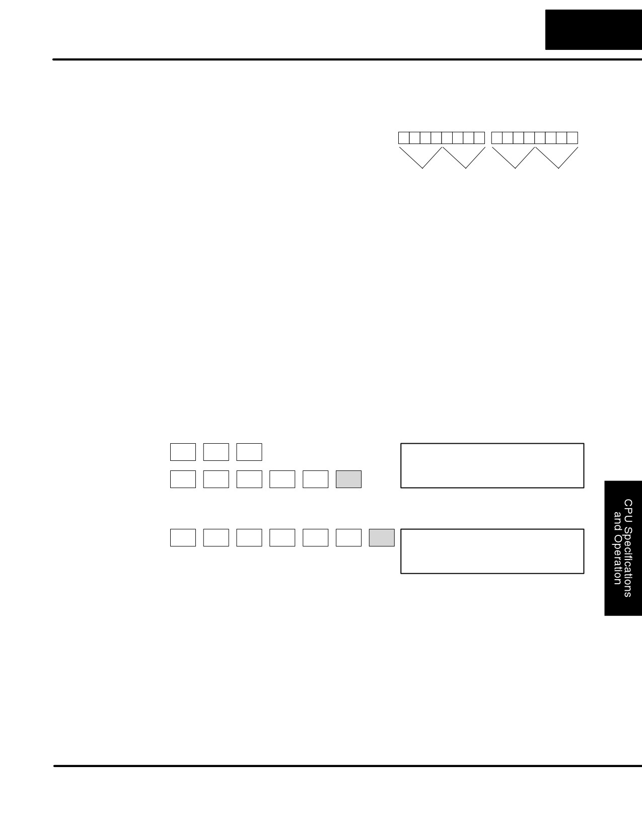
set bit 13 in V7633 (nonvolatile memory) to enable this feature; we’ll show
you how to set the bit later in this chapter.
WARNING: If bit 13 in memory location V7633 is not set, once the super capacitor
has discharged the system memory may not retain the previous mode of operation.
When this occurs, the PLC can power-up in either Run or Program Mode. There is no
way to determine which mode will be entered. Failure to adhere to this warning
greatly increases the risk of unexpected equipment startup.
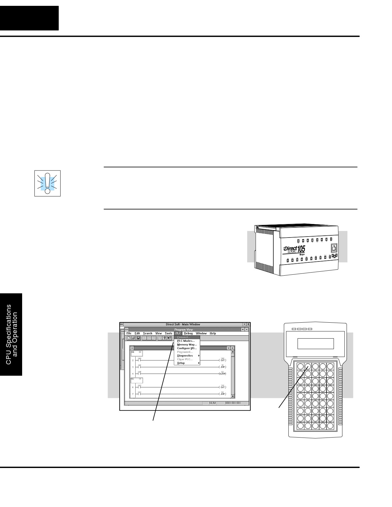
Changing Modes in The DL105 Micro PLC does not have an
the DL105 PLC
external switch to switch CPU operating
modes. You have to use a programming
device, such as the handheld programmer
or DirectSOFT32, to change the
operating mode.
You can use either DirectSOFT32 or the Handheld Programmer to change the CPU
mode of operation. With DirectSOFT32 you use a menu option in the PLC menu.
With the Handheld Programmer, you use the MODE key.
MODE
Key
Menu Options
DL105 PLC User Manual, 2nd Edition, Rev. A
4-7
CPU Specifications and Operation
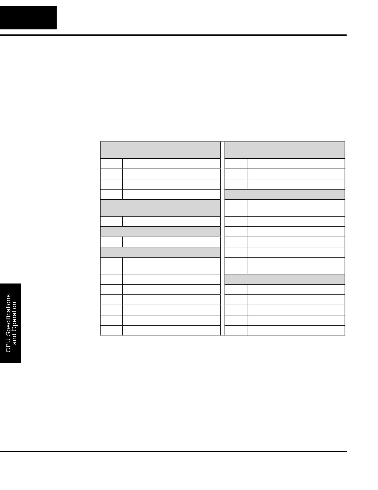
Setting Bits in
You can use the Handheld Programmer or
V7633 - 16 bits
V7633
DirectSOFT32 to set the proper bits in
CPU Setup
HSIO Mode Select
V7633.
Bit
15 14 13 12 11
10
9
8
7
6
5
4
3
2
1
0
Since you cannot access the bits
00 10 0000
01 100000
individually, you have to enter a constant
that will result in the appropriate bit being
set. The first two digits of the constant are
2
0
6
0
used to select the CPU options. The
second two digits are used with the
Codes:
Codes:
High-Speed I/O function to select various
00: Default
10: Up Counter
options. If you’re using High Speed I/O
20: Power-up in Run
20: Quadrature
functions, make sure you also enter the
30: Pulse output
appropriate code for the feature selected If
(High Speed)
you want the HSIO inputs and outputs to
40: Interrupt (High Speed)
default to regular I/O point operation, just
50: Pulse catch (High Speed)
enter 60 as the last two digits of the code.
60: Discrete Filtered
This configures all I/O points to operate
Input (default)
only as standard discrete I/O.
The diagram shows how the upper and
lower bytes of V7633 are used. For
example, if you entered 2060 into V7633,
the powerup-in-run option is selected, and
the discrete filtered inputs are selected.
The following keystrokes show how you can enter the codes into V7633 with the
D2-HPP Handheld Programmer.
Select V7633 for Monitoring
CLR
CLR
SHFT
V 7634 V7633
V
H
G
D
D
STAT
0001
0000
AND
7
6
3
3
Enter the Code
K
C
A
G
A
SHFT
ENT
JMP
2
0
6
0
V 7634 V7633
K2060
Since the changes take affect immediately, you may receive an error message. For
example, if you select Power-up in Run Mode and the CPU does not yet contain a
program, an error will occur.
DL105 PLC User Manual, 2nd Edition, Rev. A
4-8
CPU Specifications and Operation
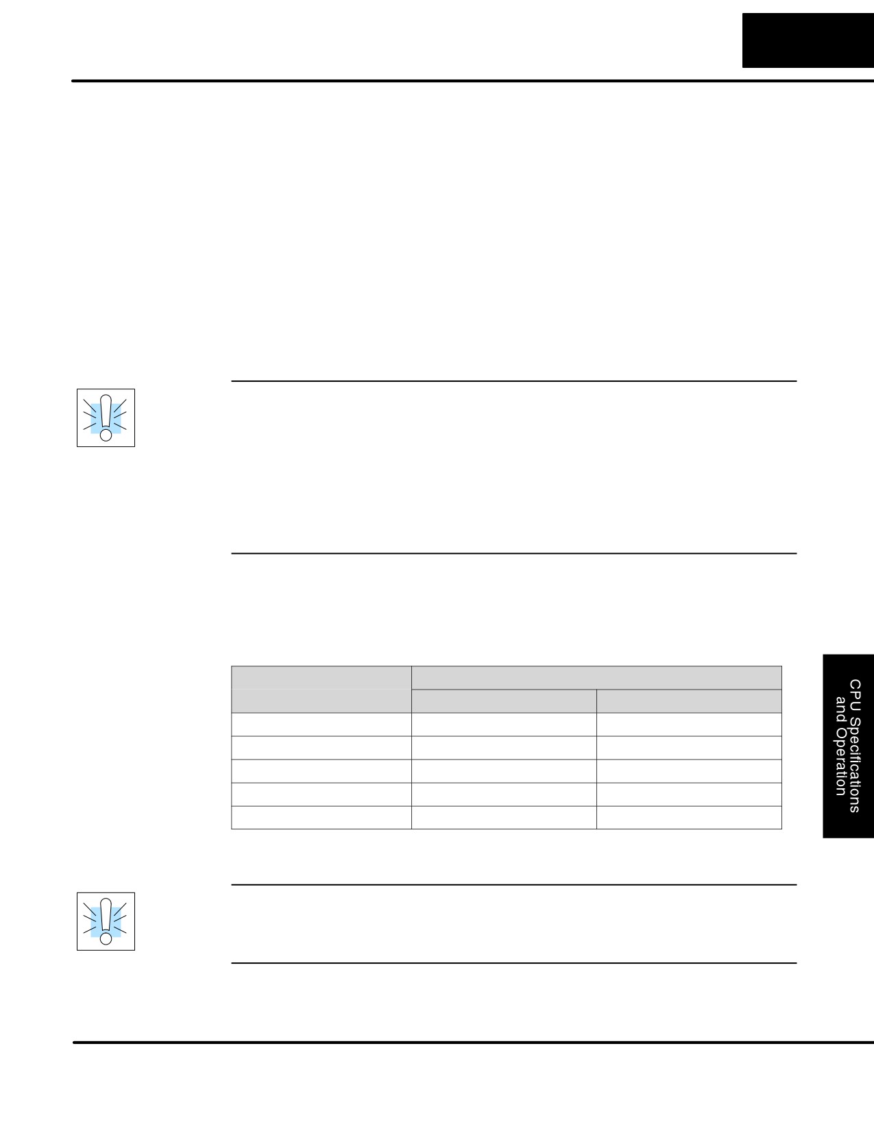
Many CPU setup tasks involve the use of Auxiliary (AUX) Functions. The AUX
Auxiliary Functions
Functions perform many different operations, ranging from clearing ladder memory,
displaying the scan time, copying programs to EEPROM in the handheld
programmer, etc. They are divided into categories that affect different system
parameters. Appendix A provides a description of the AUX functions.
You can access the AUX Functions from DirectSOFT32 or from the D2-HPP
Handheld Programmer. The manuals for those products provide step-by-step
procedures for accessing the AUX Functions. Some of these AUX Functions are
designed specifically for the Handheld Programmer setup, so they will not be
needed (or available) with the DirectSOFT32 package. The following table shows a
list of the Auxiliary functions for the Handheld Programmer.
AUX 2* — RLL Operations
AUX 6* — Handheld Programmer
Configuration
21
Check Program
61
Show Revision Numbers
22
Change Reference
62
Beeper On / Off
23
Clear Ladder Range
65
Run Self Diagnostics
24
Clear All Ladders
AUX 7* — EEPROM Operations
AUX 3* — V-Memory Operations
71
Copy CPU memory to HPP
EEPROM
31
Clear V Memory
72
Write HPP EEPROM to CPU
AUX 4* — I/O Configuration
73
Compare CPU to HPP EEPROM
41
Show I/O Configuration
74
Blank Check (HPP EEPROM)
AUX 5* — CPU Configuration
75
Erase HPP EEPROM
51
Modify Program Name
76
Show EEPROM Type (CPU and
HPP)
53
Display Scan Time
AUX 8* — Password Operations
54
Initialize Scratchpad
81
Modify Password
55
Set Watchdog Timer
82
Unlock CPU
57
Set Retentive Ranges
83
Lock CPU
58
Test Operations
5B
HSIO Configuration
DL105 PLC User Manual, 2nd Edition, Rev. A
4-9
CPU Specifications and Operation
Clearing an
Before you enter a new program, be sure to always clear ladder memory. You can
Existing Program
use AUX Function 24 to clear the complete program.
You can also use other AUX functions to clear other memory areas.
S AUX 23 — Clear Ladder Range
S AUX 24 — Clear all Ladders
S AUX 31 — Clear V Memory
Initializing System The DL105 Micro PLC maintain system parameters in a memory area often referred
Memory
to as the “scratchpad”. In some cases, you may make changes to the system setup
that will be stored in system memory. For example, if you specify a range of Control
Relays (CRs) as retentive, these changes are stored in system memory.
AUX 54 resets the system memory to the default values.
WARNING: You may never have to use this feature unless you want to clear any
setup information that is stored in system memory. Usually, you’ll only need to
initialize the system memory if you are changing programs and the old program
required a special system setup. You can usually load in new programs without ever
initializing system memory.
Remember, this AUX function will reset all system memory. If you have set special
parameters such as retentive ranges, etc. they will be erased when AUX 54 is used.
Make sure you that you have considered all ramifications of this operation before
you select it.
Setting Retentive The DL105 PLCs provide certain ranges of retentive memory by default. The default
ranges are suitable for many applications, but you can change them if your
Memory Ranges
application requires additional retentive ranges or no retentive ranges at all. (see
Appendix E) The default settings are:
DL105
Memory Area
Default Range
Available Range
Control Relays
C300 - C377
C0 - C377
V Memory
V2000 - V2377
V0 - V2377
Timers
None by default
T0 - T77
Counters
CT0 - CT77
CT0 - CT77
Stages
None by default
S0 - S377
You can use AUX 57 (see Appendix A) to set the retentive ranges. You can also use
DirectSOFT32 menus to select the retentive ranges.
WARNING: The DL105 PLCs do not have battery back-up. The super capacitor will
retain the values in the event of a power loss, but only for a short period of time,
depending on conditions. If the retentive ranges are important for your application,
make sure you program critical parameters into EEPROM locations.
DL105 PLC User Manual, 2nd Edition, Rev. A
4-10
CPU Specifications and Operation
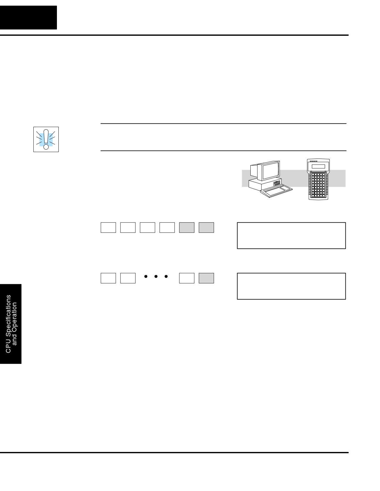
The DL105 PLCs allow you to use a password to help minimize the risk of
Using a Password
unauthorized program and/or data changes. Once you enter a password you can
“lock” the PLC against access. Once the CPU is locked you must enter the password
before you can use a programming device to change any system parameters.
You can select an 8-digit numeric password. The Micro PLCs are shipped from the
factory with a password of 00000000. All zeros removes the password protection. If
a password has been entered into the CPU you cannot just enter all zeros to remove
it. Once you enter the correct password, you can change the password to all zeros to
remove the password protection.
WARNING: Make sure you remember your password. If you forget your password
you will not be able to access the CPU. The Micro PLC must be returned to the
factory to have the password removed.
You can use the D2-HPP Handheld
Programmer or DirectSOFT32 to enter a
password. The following diagram shows how
you can enter a password with the Handheld
Programmer.
DirectSOFT32
D2-HPP
Select AUX 81
I
B
CLR
CLR
AUX
ENT
8
1
PASSWORD
00000000
Enter the new 8-digit password
X
X
X
ENT
PASSWORD
XXXXXXXX
Press CLR to clear the display
There are three ways to lock the CPU once the password has been entered.
1. If the CPU power is disconnected, the CPU will be automatically locked
against access.
2. If you enter the password with DirectSOFT32, the CPU will be
automatically locked against access when you exit DirectSOFT32.
3. Use AUX 83 to lock the CPU.
When you use DirectSOFT32, you will be prompted for a password if the CPU has
been locked. If you use the Handheld Programmer, you have to use AUX 82 to
unlock the CPU. Once you enter AUX 82, you will be prompted to enter the
password.
DL105 PLC User Manual, 2nd Edition, Rev. A
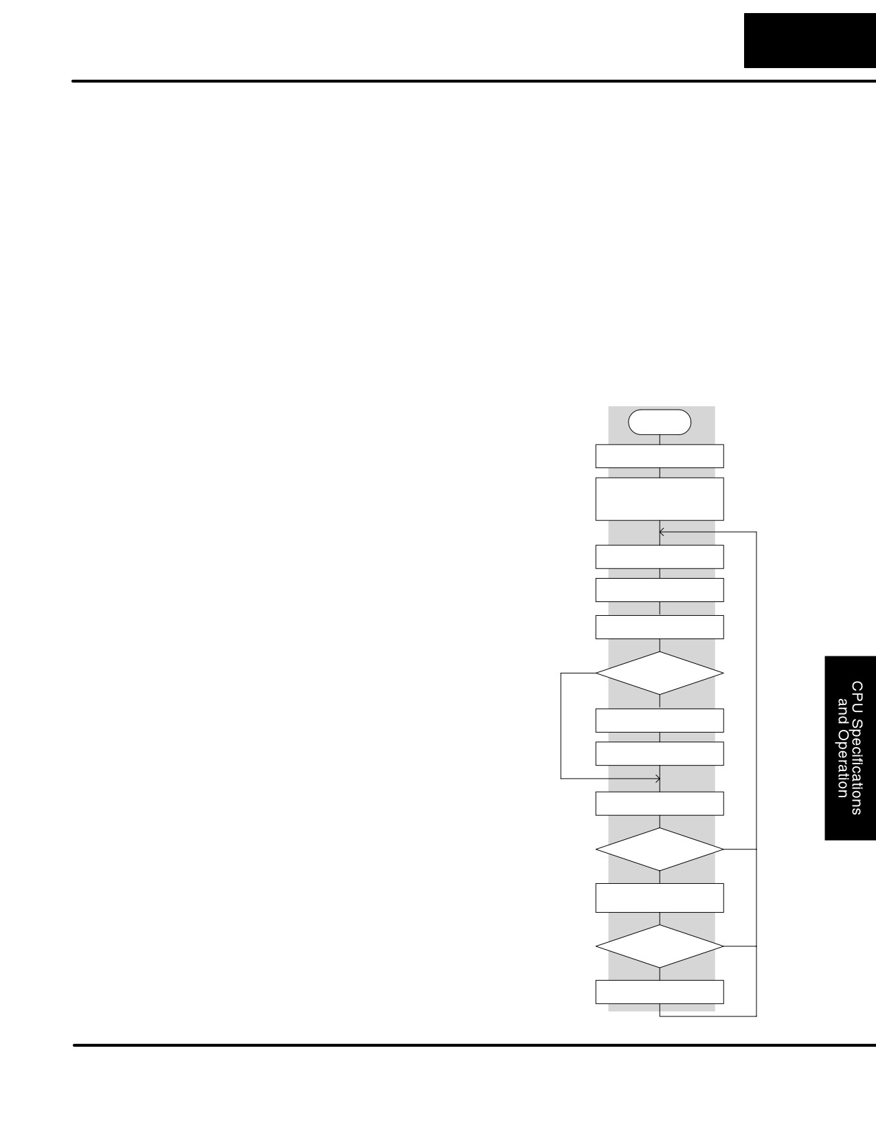
4-11
CPU Specifications and Operation
CPU Operation
Achieving the proper control for your equipment or process requires a good
understanding of how DL105 CPUs control all aspects of system operation. There
are four main areas to understand before you create your application program:
S CPU Operating System — the CPU manages all aspects of system
control. A quick overview of all the steps is provided in the next section.
S CPU Operating Modes — The two primary modes of operation are
Program Mode and Run Mode.
S CPU Timing — The two important areas we discuss are the I/O
response time and the CPU scan time.
S CPU Memory Map — DL105 CPUs offer a wide variety of resources,
such as timers, counters, inputs, etc. The memory map section shows
the organization and availability of these data types.
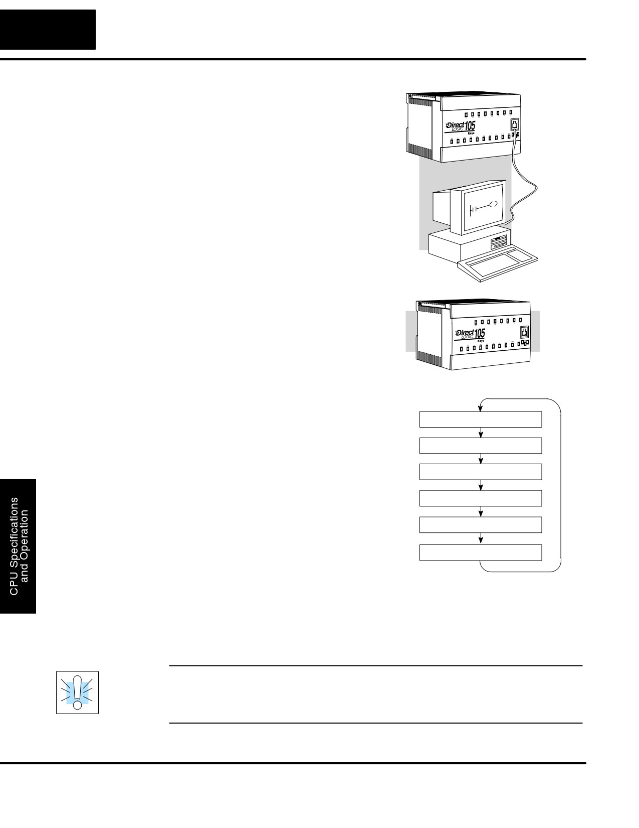
At powerup, the CPU initializes the
CPU Operating
Power up
System
internal electronic hardware. Memory
initialization starts with examining the
Initialize hardware
retentive memory settings. In general, the
contents of retentive memory is
Initialize various memory
preserved, and non-retentive memory is
based on retentive
configuration
initialized to zero
(unless otherwise
specified).
After the one-time powerup tasks, the
Update input
CPU begins the cyclical scan activity. The
flowchart to the right shows how the tasks
Service peripheral
differ, based on the CPU mode and the
existence of any errors. The “scan time” is
Update Special Relays
defined as the average time around the
task loop. Note that the CPU is always
PGM
Mode?
reading the inputs, even during program
mode. This allows programming tools to
RUN
monitor input status at any time.
Execute program
The outputs are only updated in Run
mode. In program mode, they are in the off
Update output
state.
Error detection has two levels. Non-fatal
errors are reported, but the CPU remains
Do diagnostics
in its current mode. If a fatal error occurs,
the CPU is forced into program mode and
OK
YES
OK?
the outputs go off.
NO
Report error, set flag
register, turn on LED
NO
Fatal error
YES
Force CPU into
PGM mode
DL105 PLC User Manual, 2nd Edition, Rev. A
4-12
CPU Specifications and Operation
Program Mode
In Program Mode, the CPU does not
execute the application program or update
the output points. The primary use for
Program Mode is to enter or change an
application program. You also use
Download
program mode to set up the CPU
Program
parameters, such as HSIO features,
retentive memory areas, etc.
You can use a programming device, such
as DirectSOFT32 or the D2-HPP
Handheld Programmer to place the CPU
in Program Mode.
Run Mode
In Run Mode, the CPU executes the
application program and updates the I/O
system. You can perform many operations
during Run Mode. Some of these include:
S
Monitor and change I/O point status
S
Update timer/counter preset values
Normal Run mode scan
S
Update Variable memory locations
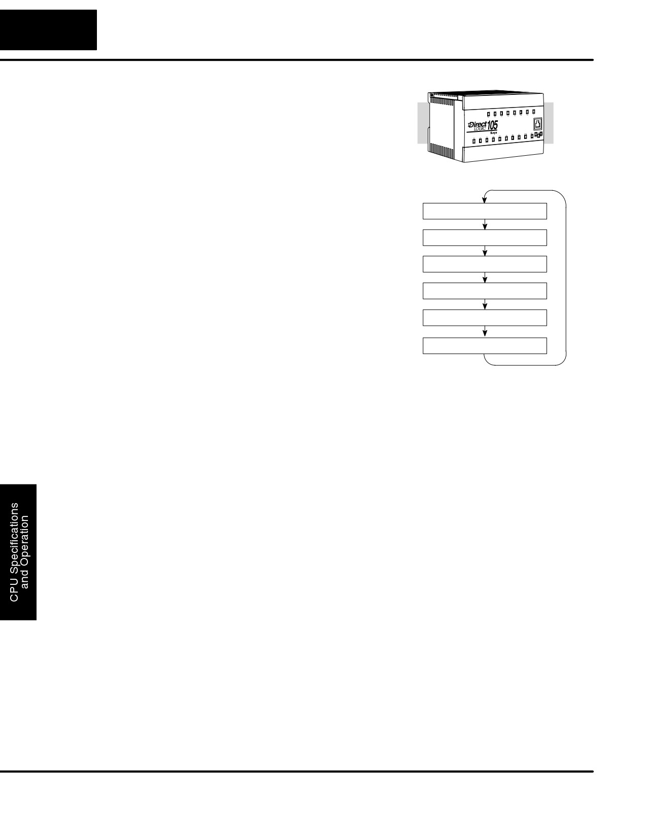
Run Mode operation can be divided into
Read Inputs
several key areas. For the vast majority of
applications, some of these execution
Service Peripherals
segments are more important than others.
For example, you need to understand how
Update Special Relays
the CPU updates the I/O points, handles
forcing operations, and solves the
Solve the Application Program
application program. The remaining
segments are not that important for most
Write Outputs
applications.
You can use DirectSOFT32 or the
Diagnostics
D2-HPP Handheld Programmer to place
the CPU in Run Mode.
You can also edit the program during Run Mode. The Run Mode Edits are not
“bumpless” to the outputs. Instead, the CPU maintains the outputs in their last state
while it accepts the new program information. If an error is found in the new program,
then the CPU will turn all the outputs off and enter the Program Mode. This feature is
discussed in more detail in Chapter 8.
WARNING: Only authorized personnel fully familiar with all aspects of the
application should make changes to the program. Changes during Run Mode
become effective immediately. Make sure you thoroughly consider the impact of any
changes to minimize the risk of personal injury or damage to equipment.
DL105 PLC User Manual, 2nd Edition, Rev. A
4-13
CPU Specifications and Operation
Read Inputs
The CPU reads the status of all inputs, then stores it in the image register. Input
image register locations are designated with an X followed by a memory location.
Image register data is used by the CPU when it solves the application program.
Of course, an input may change after the CPU has just read the inputs. Generally,
the CPU scan time is measured in milliseconds. If you have an application that
cannot wait until the next I/O update, you can use Immediate Instructions. These do
not use the status of the input image register to solve the application program. The
Immediate instructions immediately read the input status directly from the I/O
modules. However, this lengthens the program scan since the CPU has to read the
I/O point status again. A complete list of the Immediate instructions is included in
Chapter 5.
Service Peripherals
After the CPU reads the inputs from the input modules, it reads any attached
peripheral devices. This is primarily a communications service for any attached
and Force I/O
devices. For example, it would read a programming device to see if any input, output,
or other memory type status needs to be modified.
Forced I/O— temporarily changes the status of a discrete bit. For example, you may
want to force an input on, even though it is really off. This allows you to change the
point status that was stored in the image register. This value will be valid until the
image register location is written to during the next scan. This is primarily useful
during testing situations when you just need to force a bit on to trigger another event.
Forced Inputs — The CPU reads the status of X inputs during the Read Inputs
portion of the scan. When the CPU services the programming device, it logs any
request to force an X input on. If the input is used in the application program, the
ladder X contact is considered closed (on). Since an X input is a real-world input
point, the CPU will change the status when it reads the inputs on the next scan.
Forced Outputs— Outputs which are not used in the program can be forced on and
off for troubleshooting and maintenance purposes. You can temporarily allow the
forcing of any output by inserting an END coil instruction at the beginning of the
ladder program. Then you can use DirectSOFT32 or a HPP to force outputs on and
off.
The DL105 PLCs only retain the forced value for one scan. There is an exception to
this rule. For example, if the point address is greater than X11 or Y7 or it is not used in
the ladder program, then the point will maintain the forced status.
WARNING: Only authorized personnel fully familiar with all aspects of the
application should make changes to the program. Make sure you thoroughly
consider the impact of any changes to minimize the risk of personal injury or damage
to equipment.
Update Special
There are certain V-memory locations that contain Special Relays and other
Relays and Special
dedicated register information. This portion of the execution cycle makes sure these
Registers
locations get updated on every scan. Also, there are several different Special
Relays, such as diagnostic relays, etc., that are also updated during this segment.
DL105 PLC User Manual, 2nd Edition, Rev. A
4-14
CPU Specifications and Operation
Solve Application
The CPU evaluates each instruction in the
Program
application program during this segment
of the scan cycle. The instructions define
the relationship between the input
conditions and the desired output
response. The CPU uses the output
image register area to store the status of
Normal Run mode scan
the desired action for the outputs. Output
image register locations are designated
with a Y followed by a memory location.
Read Inputs
The actual outputs are updated during the
write outputs segment of the scan cycle.
Service Peripherals
There are immediate output instructions
available that will update the output points
Update Special Relays
immediately instead of waiting until the
write output segment. A complete list of
Solve the Application Program
the Immediate instructions is provided in
Chapter 5.
Write Outputs
The internal control relays (C), the stages
(S), and the variable memory (V) are also
Diagnostics
updated in this segment.
You may recall that you can force various types of points in the system. (This was
discussed earlier in this chapter.) If any I/O points or memory data have been forced,
the output image register also contains this information.
Write Outputs
Once the application program has solved the instruction logic and constructed the
output image register, the CPU writes the contents of the output image register to the
corresponding output points. Remember, the CPU also made sure that any forcing
operation changes were stored in the output image register, so the forced points get
updated with the status specified earlier.
Diagnostics
During this part of the scan, the CPU performs all system diagnostics and other tasks
such as calculating the scan time and resetting the watchdog timer. There are many
different error conditions that are automatically detected and reported by the DL105
PLCs. Appendix B contains a listing of the various error codes.
Probably one of the more important things that occurs during this segment is the
scan time calculation and watchdog timer control. The DL105 CPU has a “watchdog”
timer that stores the maximum time allowed for the CPU to complete the solve
application segment of the scan cycle. If this time is exceeded the CPU will enter the
Program Mode and turn off all outputs. The default value set from the factory is 200
ms. An error is automatically reported. For example, the Handheld Programmer
would display the following message “E003 S/W TIMEOUT” when the scan overrun
occurs.
You can use AUX 53 to view the minimum, maximum, and current scan time. Use
AUX 55 to increase or decrease the watchdog timer value.
DL105 PLC User Manual, 2nd Edition, Rev. A
4-15
CPU Specifications and Operation
I/O Response Time
Is Timing Important
I/O response time is the amount of time required for the control system to sense a
for Your
change in an input point and update a corresponding output point. In the majority of
Application?
applications, the CPU performs this task in such a short period of time that you may
never have to concern yourself with the aspects of system timing. However, some
applications do require extremely fast update times. In these cases, you may need to
know how to to determine the amount of time spent during the various segments of
operation.
There are four things that can affect the I/O response time.
S The point in the scan cycle when the field input changes states
S Input Off to On delay time
S CPU scan time
S Output Off to On delay time
The next paragraphs show how these items interact to affect the response time.
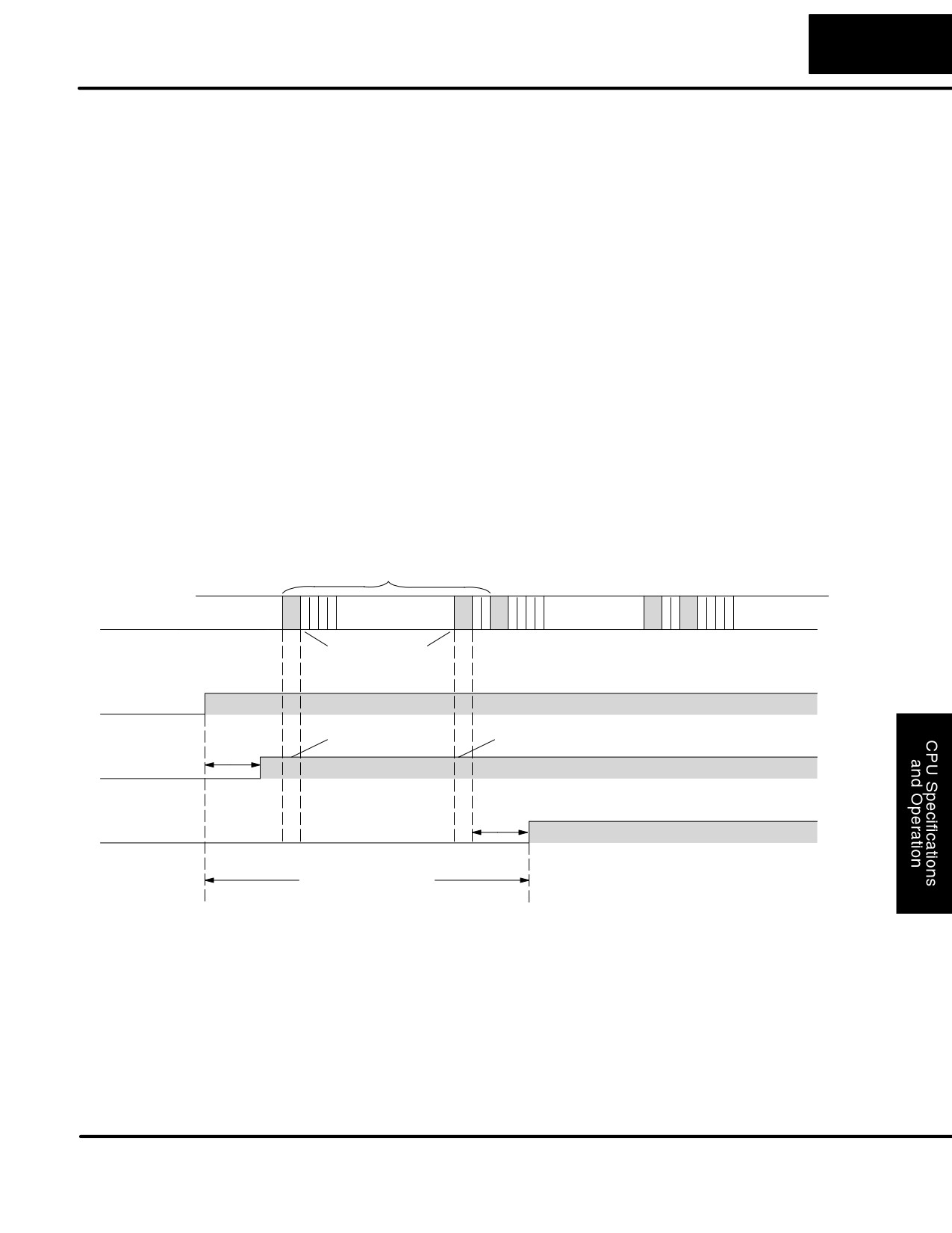
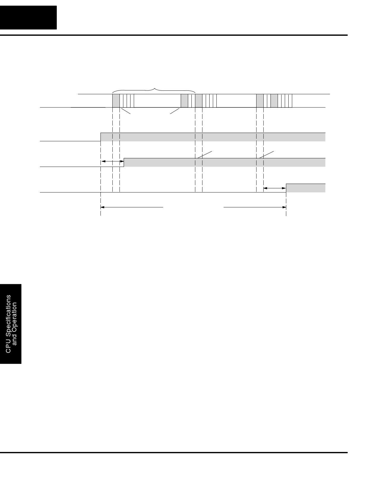
Normal Minimum
The I/O response time is shortest when the input changes just before the Read
I/O Response
Inputs portion of the execution cycle. In this case the input status is read, the
application program is solved, and the output point gets updated. The following
diagram shows an example of the timing for this situation.
Scan
Solve
Solve
Solve
Solve
Scan
Program
Program
Program
Program
Read
Write
Inputs
Outputs
Field Input
CPU Reads
CPU Writes
Inputs
Outputs
Input
Off/On Delay
Output
Off/On Delay
I/O Response Time
In this case, you can calculate the response time by simply adding the following
items:
Input Delay + Scan Time + Output Delay = Response Time
DL105 PLC User Manual, 2nd Edition, Rev. A
4-16
CPU Specifications and Operation
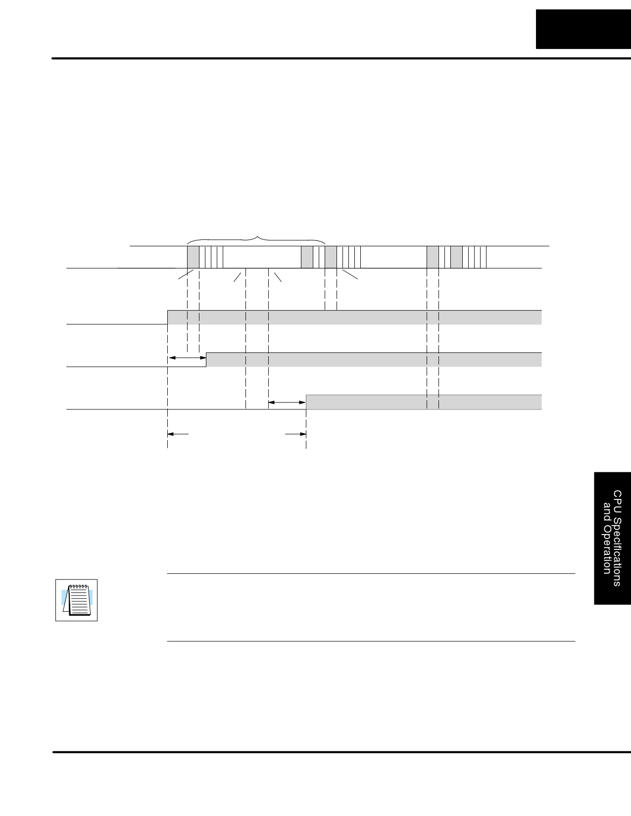
Normal Maximum
The I/O response time is longest when the input changes just after the Read Inputs
I/O Response
portion of the execution cycle. In this case the new input status does not get read until
the following scan. The following diagram shows an example of the timing for this
situation.
Scan
Solve
Solve
Solve
Solve
Scan
Program
Program
Program
Program
Read
Write
Inputs
Outputs
Field Input
CPU Reads
CPU Writes
Inputs
Outputs
Input
Off/On Delay
Output
Off/On Delay
I/O Response Time
In this case, you can calculate the response time by simply adding the following
items:
Input Delay +(2 x Scan Time) + Output Delay = Response Time
DL105 PLC User Manual, 2nd Edition, Rev. A
4-17
CPU Specifications and Operation
Improving
There are a few things you can do the help improve throughput.
Response Time
S You can choose instructions with faster execution times
S You can use immediate I/O instructions (which update the I/O points
during the program execution)
S You can use the HSIO Mode 50 Pulse Catch features designed to
operate in high-speed environments. See the Chapter 3 for details on
using this feature.
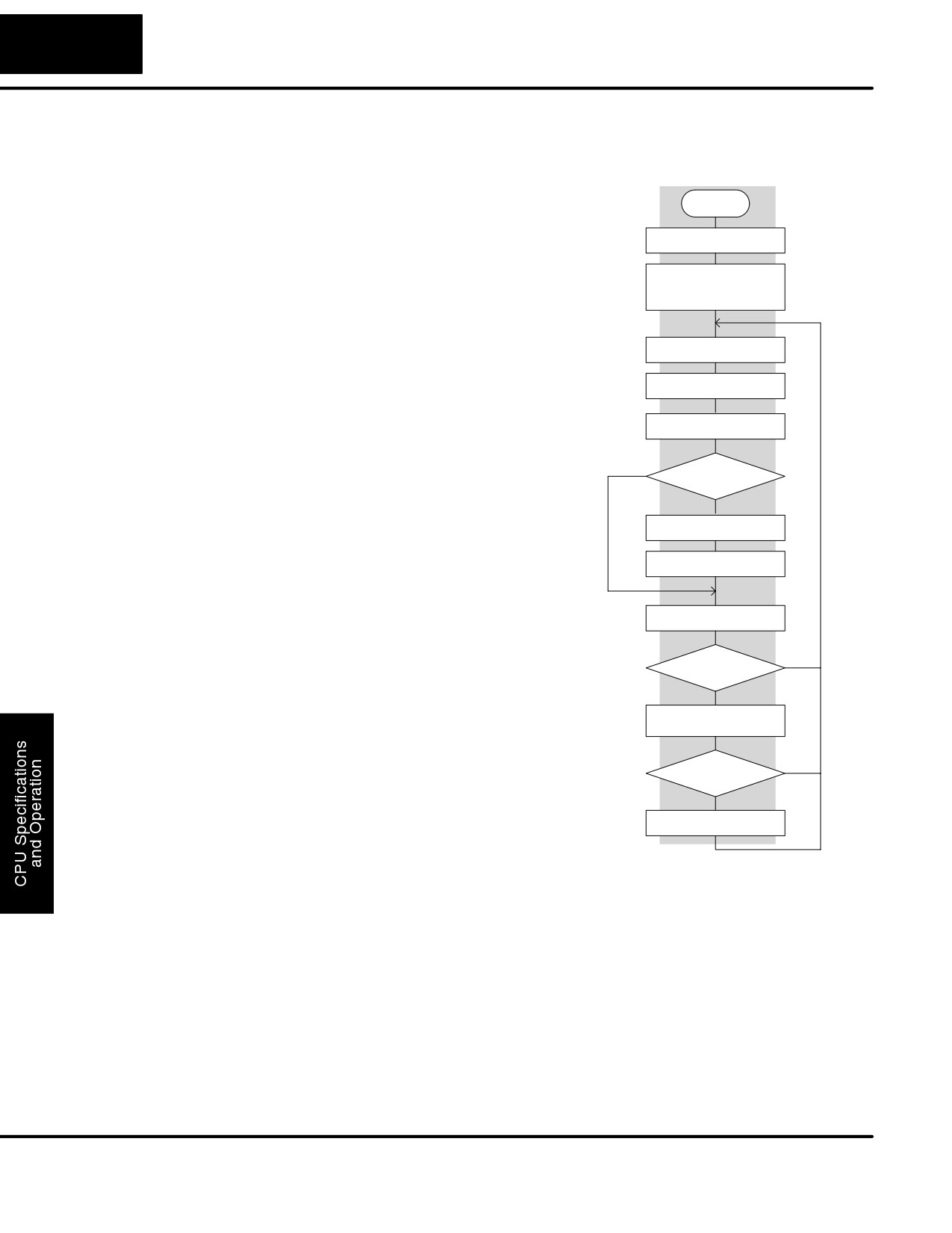
Of these three things the Immediate I/O instructions are probably the most important
and most useful. The following example shows how an immediate input instruction
and immediate output instruction would affect the response time.
Scan
Solve
Solve
Solve
Solve
Scan
Program
Program
Program
Program
Normal
Read
Write
Normal
Read
Input
Output
Write
Input
Immediate
Immediate
Outputs
Field Input
Input
Off/On Delay
Output
Off/On Delay
I/O Response Time
In this case, you can calculate the response time by simply adding the following
items.
Input Delay + Instruction Execution Time + Output Delay = Response Time
The instruction execution time would be calculated by adding the time for the
immediate input instruction, the immediate output instruction, and any other
instructions in between the two.
NOTE: Even though the immediate instruction reads the most current status from
I/O, it only uses the results to solve that one instruction. It does not use the new
status to update the image register. Therefore, any regular instructions that follow
will still use the image register values. Any immediate instructions that follow will
access the I/O again to update the status.
DL105 PLC User Manual, 2nd Edition, Rev. A
4-18
CPU Specifications and Operation
CPU Scan Time Considerations
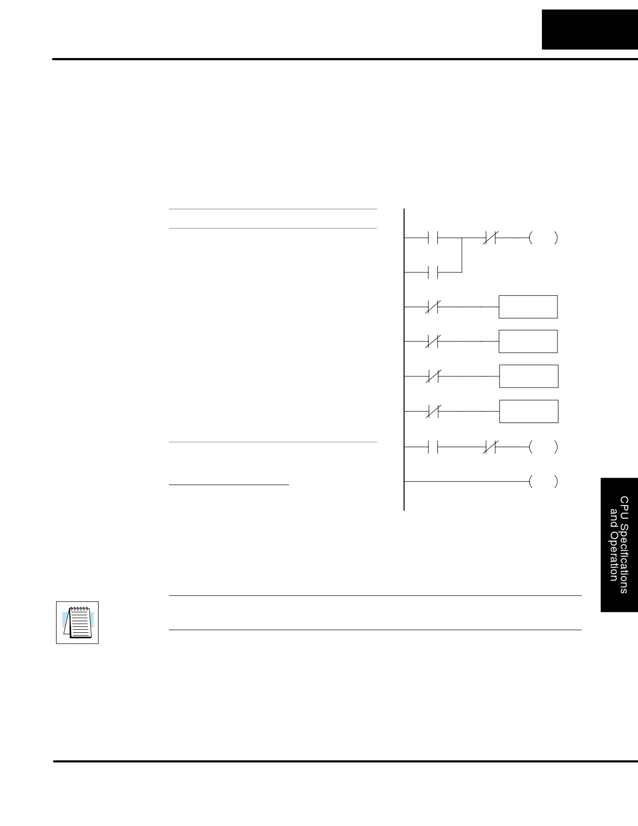
The scan time covers all the cyclical tasks
Power up
that are performed by the operating
system. You can use DirectSOFT32 or
Initialize hardware
the Handheld Programmer to display the
minimum, maximum, and current scan
Initialize various memory
times that have occurred since the
based on retentive
configuration
previous Program Mode to Run Mode
transition. This information can be very
important
when evaluating
the
Update input
performance of a system.
As we’ve shown previously there are
Service peripheral
several segments that make up the scan
cycle. Each of these segments requires a
Update Special Relays
certain amount of time to complete. Of all
the segments, the following are the most
PGM
Mode?
important.
S
Input Update
RUN
S
Peripheral Service
Execute program
S
Program Execution
Update output
S
Output Update
S
Timed Interrupt Execution
Do diagnostics
The only one you really have the most
control over is the amount of time it takes
OK
YES
to execute the application program. This is
OK?
because different instructions take
NO
different amounts of time to execute. So, if
Report error, set flag
you think you need a faster scan, then you
register, turn on LED
can try to choose faster instructions.
Your choice of I/O type and peripheral
NO
Fatal error
devices can also affect the scan time.
However, these things are usually dictated
YES
by the application.
Force CPU into
PGM mode
The following paragraphs provide some
general information on how much time
some of the segments can require.
Reading Inputs
The time required during each scan to read the input status is 40 mS. Don’t confuse
this with the I/O response time that was discussed earlier.
Writing Outputs
The time required to write the output status is 629 mS. Don’t confuse this with the I/O
response time that was discussed earlier.
DL105 PLC User Manual, 2nd Edition, Rev. A
4-19
CPU Specifications and Operation
Application
The CPU processes the program from address 0 to the END instruction. The CPU
executes the program left to right and top to bottom. As each rung is evaluated the
Program Execution
appropriate image register or memory location is updated. The time required to
solve the application program depends on the type and number of instructions used,
and the amount of execution overhead.
Just add the execution times for all the instructions in your program to determine to
total execution time. Appendix C provides a complete list of the instruction execution
times for the DL105 Micro PLC. For example, the execution time for running the
program shown below is calculated as follows:
Instruction
Time
X0
X1
Y0
STR X0
3.3 ms
OUT
OR C0
2.7 ms
ANDN X1
2.7 ms
C0
OUT Y0
3.4 ms
STRN C100
3.9 ms
C100
LD K10
62 ms
LD
K10
STRN C101
3.9 ms
OUT V2002
60 ms
C101
OUT V2002
STRN C102
3.9 ms
LD K50
62 ms
STRN C103
3.9 ms
C102
LD
OUT V2006
60 ms
K50
STR X5
3.3 ms
C103
ANDN X10
2.7 ms
OUT V2006
OUT Y3
3.4 ms
END
27 ms
X5
X10
Y3
OUT
TOTAL
308.1 ms
Overhead DL105
END
Minimum
0.86 mS
Maximum
3.85 ms
The program above takes only 308.1 ms to execute during each scan. The total scan
time is the sum of the program execution plus the overhead as shown above.
“Overhead” includes all other housekeeping and diagnostic tasks. The scan time will
vary slightly from one scan to the next, because of fluctuation in overhead tasks.
NOTE: You can move words to EEPROM from within the application program. This
can add up to 10ms per 32 word boundary.
Program Control Instructions — the DL105 PLCs have an interrupt routine
feature that changes the way a program executes. Since this instruction interrupts
normal program flow, it will have an effect on the program execution time. For
example, a timed interrupt routine with a 10 mS period interrupts the main program
execution (before the END statement) every 10 mS, so the CPU can execute the
interrupt routine. Chapter 5 provides detailed information on interrupts.
DL105 PLC User Manual, 2nd Edition, Rev. A
4-20
CPU Specifications and Operation
PLC Numbering Systems
If you are a new PLC user or are using
octal
binary
DirectLOGIC PLCs for the first time,
BCD
?
1482
please take a moment to study how our
?
3
0402
?
PLCs use numbers. You’ll find that each
?
PLC manufacturer has their own
-961428
ASCII
3A9 7
conventions on the use of numbers in their
hexadecimal
1001011011
PLCs. We want to take just a moment to
177
1011
familiarize you with how numbers are
?
decimal
used in DirectLOGIC PLCs. The
A
72B
information you learn here applies to all
-300124
?
our PLCs!
As any good computer does, PLCs store and manipulate numbers in binary form:
just ones and zeros. So why do we have to deal with numbers in so many different
forms? Numbers have meaning, and some representations are more convenient
than others for particular purposes. Sometimes we use numbers to represent a size
or amount of something. Other numbers refer to locations or addresses, or to time. In
science we attach engineering units to numbers to give a particular meaning.
PLCs offer a fixed amount of resources, depending on the model and configuration.
PLC Resources
We use the word “resources” to include variable memory (V-memory), I/O points,
timers, counters, etc. Most modular PLCs allow you to add I/O points in groups of
eight. In fact, all the resources of our PLCs are counted in octal. It’s easier for
computers to count in groups of eight than ten, because eight is an even power of 2.
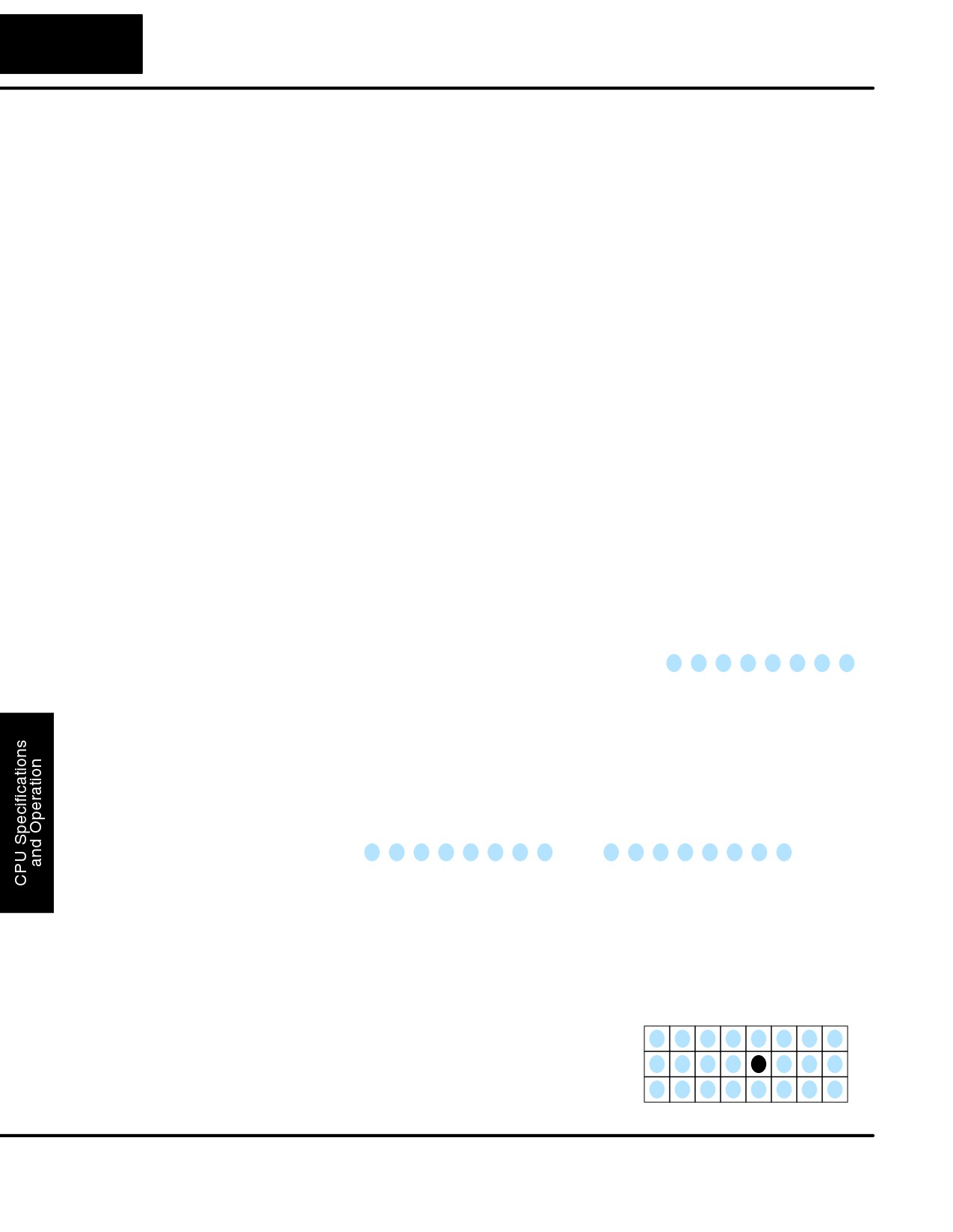
Octal means simply counting in groups of
Decimal
1
2
3
4
5
6
7
8
eight things at a time. In the figure to the
right, there are eight circles. The quantity
in decimal is “8”, but in octal it is “10” (8 and
Octal
1
2
3
4
5
6
7
10
9 are not valid in octal). In octal, “10”
means 1 group of 8 plus 0 (no individuals).
In the figure below, we have two groups of eight circles. Counting in octal we have
“20” items, meaning 2 groups of eight, plus 0 individuals Don’t say “twenty”, say
“two-zero octal”. This makes a clear distinction between number systems.
Decimal
1
2
3
4
5
6
7
8
9 10 11 12 13 14 15 16
Octal
1
2
3
4
5
6
7
10
11 12 13 14 15
16 17 20
After counting PLC resources, it’s time to access PLC resources (there’s a
difference). The CPU instruction set accesses resources of the PLC using octal
addresses. Octal addresses are the same as octal quantities, except they start
counting at zero. The number zero is significant to a computer, so we don’t skip it.
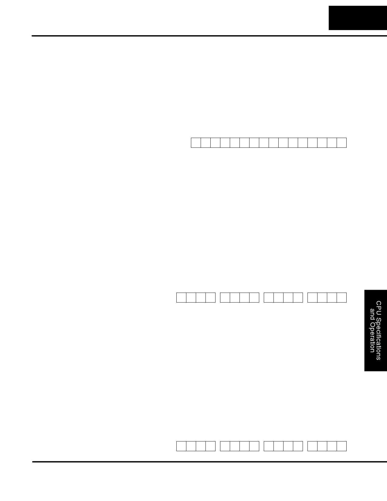
Our circles are in an array of square
X=
0
1
2
3
4
5
6
7
containers to the right. To access a
resource, our PLC instruction will address
X
its location using the octal references
1 X
shown. If these were counters, “CT14”
2 X
would access the black circle location.
DL105 PLC User Manual, 2nd Edition, Rev. A
4-21
CPU Specifications and Operation
V-Memory
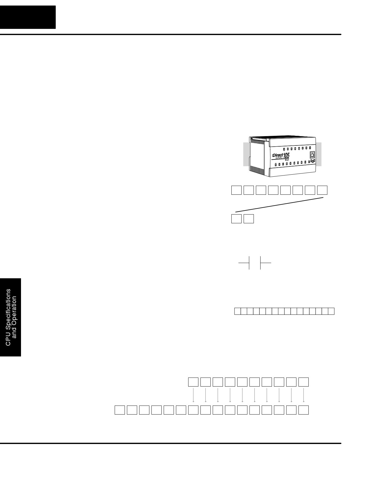
Variable memory (called “V-memory”) stores data for the ladder program and for
configuration settings
(see Appendix E). V-memory locations and V-memory
addresses are the same thing, and are numbered in octal. For example, V2073 is a
valid location, while V1983 is not valid (“9” and “8” are not valid octal digits).
Each V-memory location is one data word wide, meaning 16 bits. For configuration
registers, our manuals will show each bit of a V-memory word. The least significant
bit (LSB) will be on the right, and the most significant bit (MSB) on the left. We use the
word “significant”, referring to the relative binary weighting of the bits.
VĆmemory address
VĆmemory data
(octal)
(binary)
MSB
LSB
V2017
0
1
0
0
1
1
1
0
0
0
1
0
1
0
0
1
V-memory data is 16-bit binary, but we rarely program the data registers one bit at a
time. We use instructions or viewing tools that let us work with decimal, octal, and
hexadecimal numbers. All these are converted and stored as binary for us.
A frequently-asked question is “How do I tell if a number is octal, BCD, or hex”? The
answer is that we usually cannot tell just by looking at the data... but it does not really
matter. What matters is: the source or mechanism which writes data into a
V-memory location and the thing which later reads it must both use the same data
type (i.e., octal, hex, binary, or whatever). The V-memory location is just a storage
box... that’s all. It does not convert or move the data on its own.
Since humans naturally count in decimal (10 fingers, 10 toes), we prefer to enter and
Binary-Coded
view PLC data in decimal as well. However, computers are more efficient in using
Decimal Numbers
pure binary numbers. A compromise solution between the two is Binary-Coded
Decimal (BCD) representation. A BCD digit ranges from 0 to 9, and is stored as four
binary bits (a nibble). This permits each V-memory location to store four BCD digits,
with a range of decimal numbers from 0000 to 9999.
BCD number
4
9
3
6
VĆmemory storage
0
1
0
0
1
0
0
1
0
0
1
1
0
1
1
0
In a pure binary sense, a 16-bit word can represent numbers from 0 to 65535. In
storing BCD numbers, the range is reduced to only 0 to 9999. Many math
instructions use Binary-Coded Decimal (BCD) data, and DirectSOFT32 and the
handheld programmer allow us to enter and view data in BCD.
Hexadecimal
Hexadecimal numbers are similar to BCD numbers, except they utilize all possible
Numbers
binary values in each 4-bit digit. They are base-16 numbers so we need 16 different
digits. To extend our decimal digits 0 through 9, we use A through F as shown.
Decimal
0 1
2
3
4
5
6
7
8
9 10 11 12 13 14 15
Hexadecimal
0 1
2
3
4
5
6
7
8
9
A B C D E F
A 4-digit hexadecimal number can represent all 65536 values in a V-memory word.
The range is from 0000 to FFFF (hex). PLCs often need this full range for sensor
data, etc. Hexadecimal is just a convenient way for humans to view full binary data.
Hexadecimal number
A
7
F
4
VĆmemory storage
1
0
1
0
0
1
1
1
1
1
1
1
0
1
0
0
DL105 PLC User Manual, 2nd Edition, Rev. A
4-22
CPU Specifications and Operation
Memory Map
With any PLC system, you generally have many different types of information to
process. This includes input device status, output device status, various timing
elements, parts counts, etc. It is important to understand how the system represents
and stores the various types of data. For example, you need to know how the system
identifies input points, output points, data words, etc. The following paragraphs
discuss the various memory types used in DL105 Micro PLCs. A memory map
overview for the CPU follows the memory descriptions.
Octal Numbering
All memory locations and resources are
System
numbered in Octal (base 8). For example,
the diagram shows how the octal
numbering system works for the discrete
input points. Notice the octal system does
not contain any numbers with the digits 8
or 9.
X0
X1
X2
X3
X4
X5
X6
X7
X10
X11
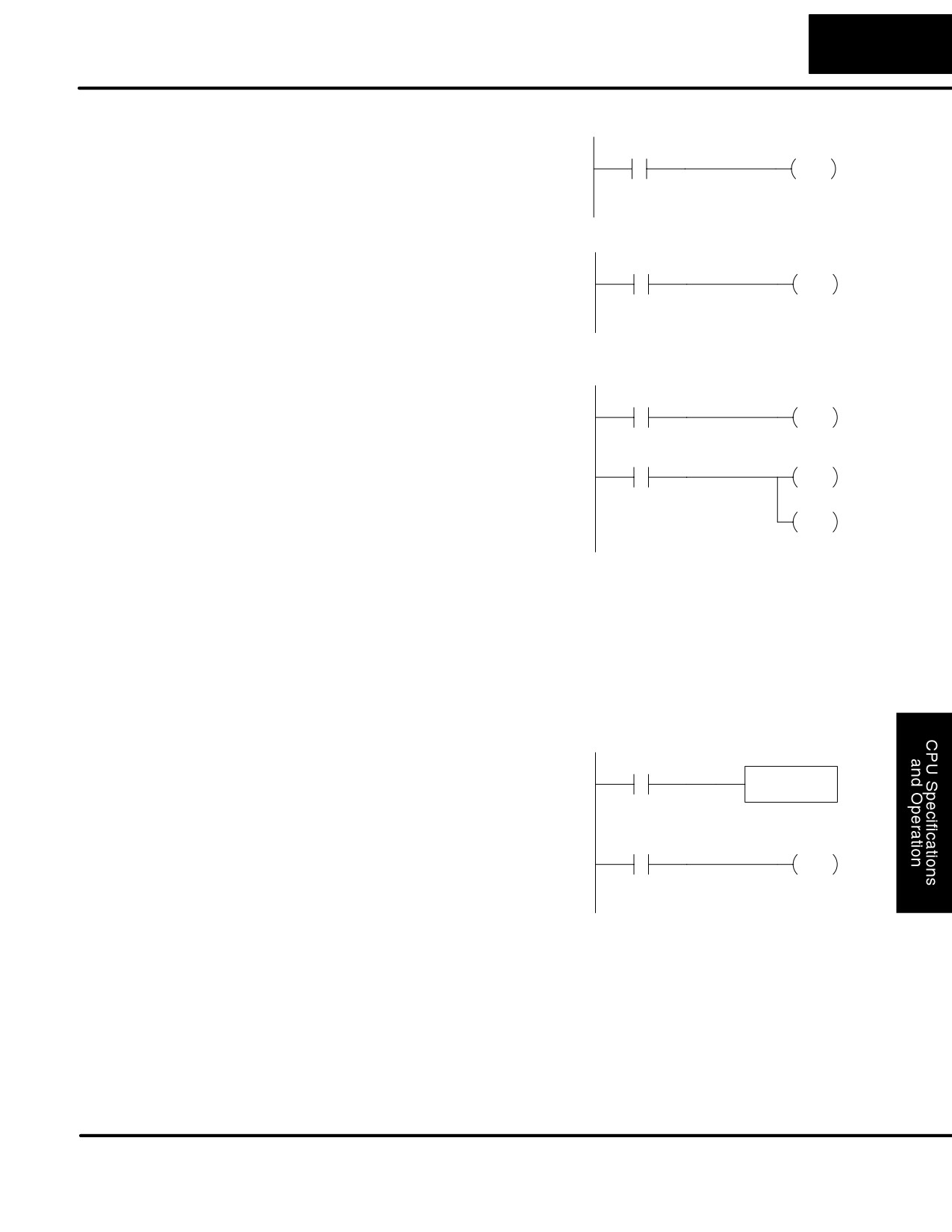
Discrete and Word
As you examine the different memory
Discrete - On or Off, 1 bit
Locations
types, you’ll notice two types of memory
X0
in the DL105, discrete and word memory.
Discrete memory is one bit that can be
either a 1 or a 0. Word memory is referred
to as V memory (variable) and is a 16-bit
location normally used to manipulate
data/numbers, store data/numbers, etc.
Some information is automatically stored
Word Locations - 16 bits
in V memory. For example, the timer
01 01 000000100101
current values are stored in V memory.
V Memory
The discrete memory area is for inputs, outputs, control relays, special relays,
Locations for
stages, timer status bits and counter status bits. However, you can also access the
Discrete Memory
bit data types as a V-memory word. Each V-memory location contains
16
Areas
consecutive discrete locations. For example, the following diagram shows how the X
input points are mapped into V-memory locations.
10 Discrete (X) Input Points
X11
X10
X7
X6
X5
X4
X3
X2
X1
X0
Bit #
15
14
13
12
11
10
9
8
7
6
5
4
3
2
1
0
V40400
These discrete memory areas and their corresponding V memory ranges are listed
in the memory area table for DL105 Micro PLCs on the following pages.
DL105 PLC User Manual, 2nd Edition, Rev. A
4-23
CPU Specifications and Operation
Input Points
The discrete input points are noted by an
(X Data Type)
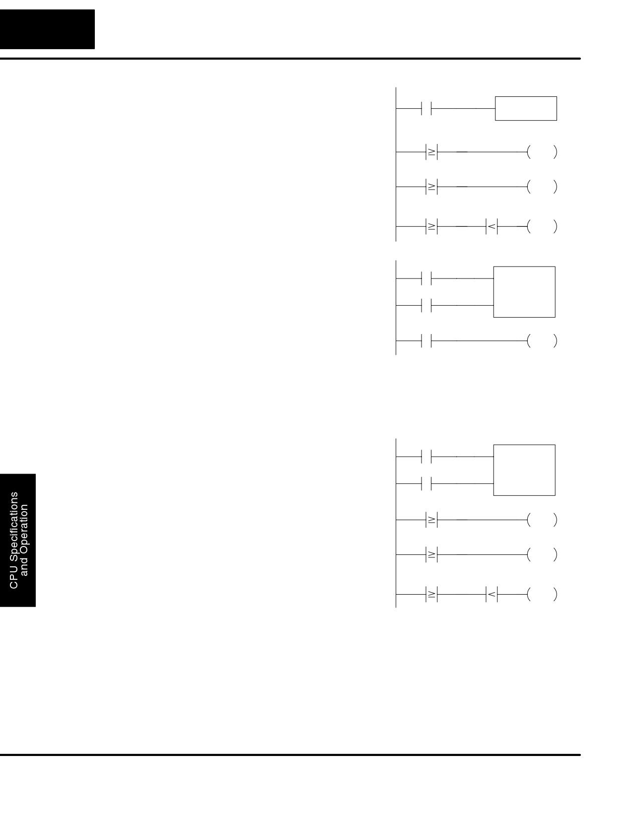
X data type. There are 10 discrete input
X0
Y0
OUT
points available with DL105 CPUs. In this
example, the output point Y0 will be
turned on when input X0 energizes.
Output Points
The discrete output points are noted by a
(Y Data Type)
Y data type. There are 128 discrete
X1
Y1
OUT
output points available with DL105
CPUs. In this example, output point Y1
will be turned on when input X1
energizes.
Control Relays
Control relays are discrete bits normally
(C Data Type)
used to control the user program. The
X10
C5
OUT
control relays do not represent a real
world device, that is, they cannot be
physically tied to switches, output coils,
C5
Y10
etc. They are internal to the CPU.
OUT
Because of this, control relays can be
Y20
programmed as discrete inputs or
OUT
discrete outputs. These locations are
used in programming the discrete
memory locations
(C) or the
corresponding word location which
contains
16 consecutive discrete
locations.
In this example, memory location C5 will
energize when input X10 turns on. The
second rung shows a simple example of
how to use a control relay as an input.
Timers and
Timer status bits reflect the relationship
Timer Status Bits
between the current value and the preset
X0
TMR
T1
(T Data type)
value of a specified timer. The timer
K30
status bit will be on when the current
value is equal or greater than the preset
value of a corresponding timer.
T1
Y12
When input X0 turns on, timer T1 will
OUT
start. When the timer reaches the preset
of
3 seconds (K of 30) timer status
contact T1 turns on. When T1 turns on,
output Y12 turns on. Turning off X0
resets the timer.
DL105 PLC User Manual, 2nd Edition, Rev. A
4-24
CPU Specifications and Operation
Timer Current
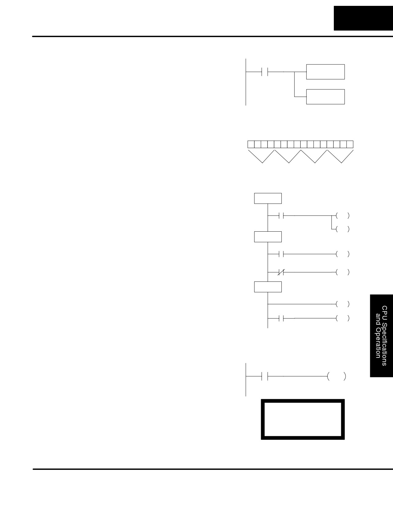
As mentioned earlier, some information
X0
Values
is automatically stored in V memory. This
TMR
T1
(V Data Type)
is true for the current values associated
K1000
with timers. For example, V0 holds the
current value for Timer 0, V1 holds the
V1
K30
Y2
current value for Timer 1, etc.
OUT
The primary reason for this is
V1
K50
Y3
programming flexibility. The example
OUT
shows how you can use relational
contacts to monitor several time intervals
V1
K75
V1
K100
Y4
from a single timer.
OUT
Counters and
Counter status bits that reflect the
X0
CNT
CT3
Counter Status
relationship between the current value
K10
Bits
and the preset value of a specified
X1
(CT Data type)
counter. The counter status bit will be on
when the current value is equal to or
greater than the preset value of a
CT3
Y2
corresponding counter.
OUT
Each time contact X0 transitions from off to on, the counter increments by one. (If X1
comes on, the counter is reset to zero.) When the counter reaches the preset of 10
counts (K of 10) counter status contact CT3 turns on. When CT3 turns on, output
Y12 turns on.
Counter Current
Just like the timers, the counter current
X0
CNT
CT3
Values
values are also automatically stored in V
K10
(V Data Type)
memory. For example, V1000 holds the
X1
current value for Counter CT0, V1001
holds the current value for Counter CT1,
etc.
V1003
K1
Y2
The primary reason for this is
OUT
programming flexibility. The example
shows how you can use relational
V1003
K3
Y3
OUT
contacts to monitor the counter values.
V1003
K5
V1003
K8
Y4
OUT
DL105 PLC User Manual, 2nd Edition, Rev. A
4-25
CPU Specifications and Operation
Word Memory
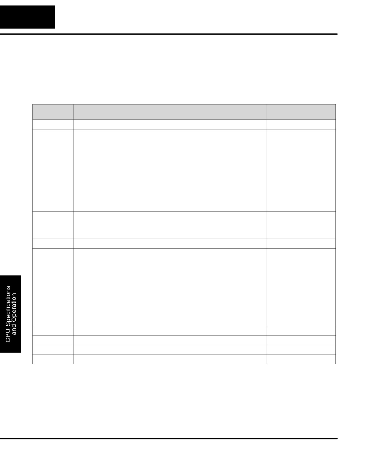
Word memory is referred to as V memory
(V Data Type)
(variable) and is a
16-bit location
X0
LD
normally
used
to
manipulate
K1345
data/numbers, store data/numbers, etc.
(see Appendix E).
OUT V2000
Some information is automatically stored
in V memory. For example, the timer
current values are stored in V memory.
The example shows how a four-digit
BCD constant is loaded into the
Word Locations - 16 bits
accumulator and then stored in a
V-memory location.
00 01 00110100010
1
1
3
4
5
Stages
Ladder Representation
(S Data type)
Stages are used in RLLPLUS Stage
ISG
programs to create a structured
S0000
Wait forStart
program, similar to a flowchart. Each
Start
S1
program stage denotes a program
JMP
segment. When the program segment,
X0
S500
or stage, is active, the logic within that
JMP
SG
segment is executed. If the stage is off, or
Check for a Part
S0001
inactive, the logic is not executed and the
Part
Present
S2
CPU skips to the next active stage. (See
JMP
Chapter 7 for a more detailed description
X1
Part
of RLLPLUS Stage programming.)
Present
S6
JMP
Each stage also has a discrete status bit
X1
that can be used as an input to indicate
SG
S0002
Clamp the part
whether the stage is active or inactive. If
the stage is active, then the status bit is
Clamp
SET
on. If the stage is inactive, then the status
S400
Part
Locked
S3
bit is off. This status bit can also be turned
JMP
on or off by other instructions, such as the
X2
SET or RESET instructions. This allows
you to easily control stages throughout
the program.
Special Relays
Special relays are discrete memory
(SP Data Type)
locations with pre-defined functionality.
SP5
C10
There are many different types of special
OUT
relays. For example, some aid in
program development, others provide
system operating status information, etc.
Appendix D provides a complete listing of
SP4: 1 second clock
the special relays.
SP5: 100 ms clock
In this example, control relay C10 will
SP6: 50 ms clock
energize for 50 ms and de-energize for
50 ms because SP5 is a pre-defined
relay that will be on for 50 ms and off for
50 ms.
DL105 PLC User Manual, 2nd Edition, Rev. A
4-26
CPU Specifications and Operation
DL105 System V-memory
System Parameters
The DL105 PLCs reserve several V-memory locations for storing system
and Default Data
parameters or certain types of system data. These memory locations store things
Locations
like the error codes, High-Speed I/O data, and other
types of system setup
(V Data Type)
information.
System
Description of Contents
Default Values / Ranges
V-memory
V2320-V2377
The default location for multiple preset values for the High-Speed Counter
N/A
V7620-V7627
Locations for DV-1000 operator interface parameters
V7620
Sets the V-memory location that contains the value.
V0 - V2377
V7621
Sets the V-memory location that contains the message.
V0 - V2377
V7622
Sets the total number (1 - 16) of V-memory locations to be displayed.
1 - 16
V7623
Sets the V-memory location that contains the numbers to be displayed.
V0 - V2377
V7624
Sets the V-memory location that contains the character code to be displayed.
V0 - V2377
V7625
Contains the function number that can be assigned to each key.
V-memory location for X,
Y, or C points used.
V7626
Powerup operational mode.
0, 1, 2, 12, 3
V7627
Change preset value.
0000 to 9999
V7630
Starting location for the multi-step presets for channel 1. The default value is
Default: V2320
2320, which indicates the first value should be obtained from V2320. Since
Range: V0 - V2320
there are 24 presets available, the default range is V2320 - V2377. You can
change the starting point if necessary.
V7631-V7632
Not used
N/A
V7633
Sets the desired function code for the high speed counter, interrupt, pulse
Default: 0060
catch, pulse train, and input filter. Location is also used for setting the
Lower Byte Range:
power-up in Run Mode option.
Range:
10 - Counter
20 - Quadrature
30 - Pulse Out
40 - Interrupt
50 - Pulse Catch
60 - Filtered
discrete In.
Upper Byte Range:
Bits 8 - 12, 14,15: Unused
Bit 13: Power-up in Run
V7634
X0 Setup Register for High-Speed I/O functions
Default: 1006
V7635
X1 Setup Register for High-Speed I/O functions
Default: 1006
V7636
X2 Setup Register for High-Speed I/O functions
Default: 1006
V7637
X3 Setup Register for High-Speed I/O functions
Default: 1006
DL105 PLC User Manual, 2nd Edition, Rev. A
4-27
CPU Specifications and Operation
System
Description of Contents
Default Values / Ranges
V-memory
V7640-V7647
Not used
N/A
V7751
Fault Message Error Code — stores the 4-digit code used with the FAULT
N/A
instruction when the instruction is executed.
V7752-V7754
Not used
N/A
V7755
Error code — stores the fatal error code.
V7756
Error code — stores the major error code.
V7757
Error code — stores the minor error code.
V7760-V7762
Not used
V7763
Program address where syntax error exists
N/A
V7764
Syntax error code
N/A
V7765
Scan — stores the total number of scan cycles that have occurred since the
N/A
last Program Mode to Run Mode transition.
V7666-V7774
Not used
N/A
V7775
Scan — stores the current scan time (milliseconds).
N/A
V7776
Scan — stores the minimum scan time that has occurred since the last
N/A
Program Mode to Run Mode transition (milliseconds).
V7777
Scan — stores the maximum scan time that has occurred since the last
N/A
Program Mode to Run Mode transition (milliseconds).
DL105 PLC User Manual, 2nd Edition, Rev. A
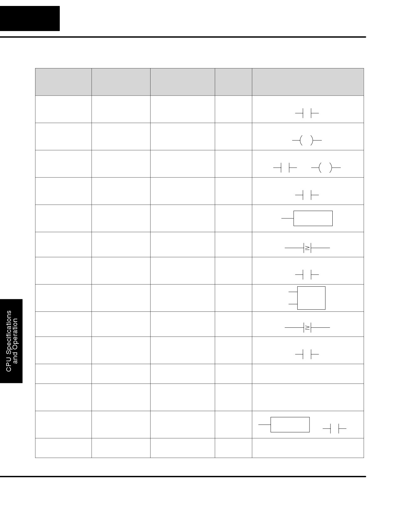
4-28
CPU Specifications and Operation
DL105 Memory
Map
Memory Type
Discrete Memory
Word Memory
Qty.
Symbol
Reference
Reference
Decimal
(octal)
(octal)
Input Points
X0 - X177
V40400 - V40407
128
X0
(See note 1)
Output Points
Y0 - Y177
V40500 - V40507
128
Y0
(See note 1)
Control Relays
C0 - C377
V40600 - V40617
256
C0
C0
Special Relays
SP0 - SP117
V41200 - V41204
112
SP0
SP540 - SP577
V41226 - V41227
Timers
T0 - T77
64
TMR
T0
K100
Timer Current
None
V0 - V77
64
V0
K100
Values
Timer Status Bits
T0 - T77
V41100 - V41103
64
T0
Counters
CT0 - CT77
64
CNT CT0
K10
Counter
None
V1000 - V1077
64
V1000
K100
Current Values
Counter Status
CT0 - CT77
V41140 - V41143
64
CT0
Bits
Data Words
None
V2000 - V2377
256
None specific, used with many
(See Appendix E)
instructions
Data Words
None
V4000 - V4177
128
None specific, used with many
Non-volatile
instructions
(See Appendix E)
Stages
S0 - S377
V41000 - V41017
256
S0
SG
S 001
System
None
V7620 - V7647
48
None specific, used for various
parameters
V7750-V7777
purposes
1 - The DL105 systems are limited to 10 discrete inputs and 8 discrete outputs with the present available hardware, but 128 point addresses exist.
DL105 PLC User Manual, 2nd Edition, Rev. A
4-29
CPU Specifications and Operation
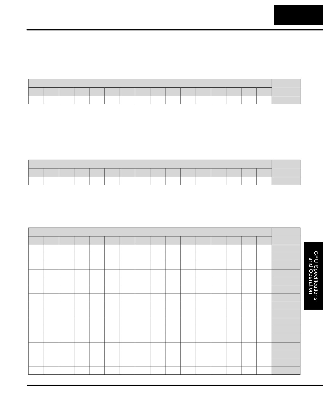
X Input Bit Map
This table provides a listing of individual Input points associated with each V-memory address bit for the
DL105’s ten physical inputs. Actual available references are X0 to X177 (V40400 - V40407).
MSB
DL105 Input (X) Points
LSB
Address
17
16
15
14
13
12
11
10
7
6
5
4
3
2
1
0
–
-
-
-
-
-
011
010
007
006
005
004
003
002
001
000
V40400
Y Output Bit Map
This table provides a listing of individual output points associated with each V-memory address bit for the
DL105’s eight physical outputs. Actual available references are Y0 to Y177 (V40500 - V40507).
MSB
DL105 Output (Y) Points
LSB
Address
17
16
15
14
13
12
11
10
7
6
5
4
3
2
1
0
–
-
-
-
-
-
-
-
007
006
005
004
003
002
001
000
V40500
Control Relay Bit Map
This table provides a listing of the individual control relays associated with each V-memory address bit.
MSB
DL105 Control Relays (C)
LSB
Address
17
16
15
14
13
12
11
10
7
6
5
4
3
2
1
0
017
016
015
014
013
012
011
010
007
006
005
004
003
002
001
000
V40600
037
036
035
034
033
032
031
030
027
026
025
024
023
022
021
020
V40601
057
056
055
054
053
052
051
050
047
046
045
044
043
042
041
040
V40602
077
076
075
074
073
072
071
070
067
066
065
064
063
062
061
060
V40603
117
116
115
114
113
112
111
110
107
106
105
104
103
102
101
100
V40604
137
136
135
134
133
132
131
130
127
126
125
124
123
122
121
120
V40605
157
156
155
154
153
152
151
150
147
146
145
144
143
142
141
140
V40606
177
176
175
174
173
172
171
170
167
166
165
164
163
162
161
160
V40607
217
216
215
214
213
212
211
210
207
206
205
204
203
202
201
200
V40610
237
236
235
234
233
232
231
230
227
226
225
224
223
222
221
220
V40611
257
256
255
254
253
252
251
250
247
246
245
244
243
242
241
240
V40612
277
276
275
274
273
272
271
270
267
266
265
264
263
262
261
260
V40613
317
316
315
314
313
312
311
310
307
306
305
304
303
302
301
300
V40614
337
336
335
334
333
332
331
330
327
326
325
324
323
322
321
320
V40615
357
356
355
354
353
352
351
350
347
346
345
344
343
342
341
340
V40616
377
376
375
374
373
372
371
370
367
366
365
364
363
362
361
360
V40617
DL105 PLC User Manual, 2nd Edition, Rev. A
4-30
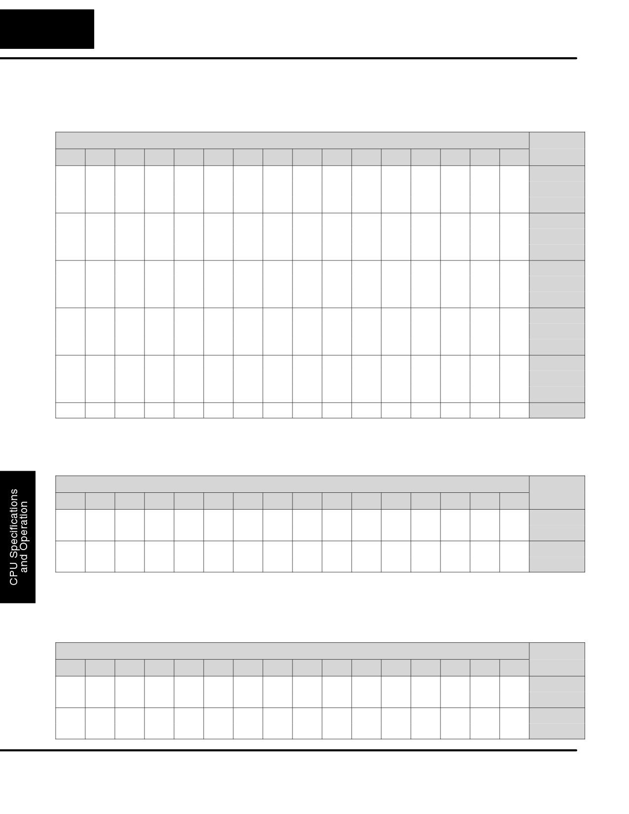
CPU Specifications and Operation
Stage Control / Status Bit Map
This table provides a listing of individual Staget control bits associated with each V-memory address bit.
MSB
DL105 Stage (S) Control Bits
LSB
Address
17
16
15
14
13
12
11
10
7
6
5
4
3
2
1
0
017
016
015
014
013
012
011
010
007
006
005
004
003
002
001
000
V41000
037
036
035
034
033
032
031
030
027
026
025
024
023
022
021
020
V41001
057
056
055
054
053
052
051
050
047
046
045
044
043
042
041
040
V41002
077
076
075
074
073
072
071
070
067
066
065
064
063
062
061
060
V41003
117
116
115
114
113
112
111
110
107
106
105
104
103
102
101
100
V41004
137
136
135
134
133
132
131
130
127
126
125
124
123
122
121
120
V41005
157
156
155
154
153
152
151
150
147
146
145
144
143
142
141
140
V41006
177
176
175
174
173
172
171
170
167
166
165
164
163
162
161
160
V41007
217
216
215
214
213
212
211
210
207
206
205
204
203
202
201
200
V41010
237
236
235
234
233
232
231
230
227
226
225
224
223
222
221
220
V41011
257
256
255
254
253
252
251
250
247
246
245
244
243
242
241
240
V41012
277
276
275
274
273
272
271
270
267
266
265
264
263
262
261
260
V41013
317
316
315
314
313
312
311
310
307
306
305
304
303
302
301
300
V41014
337
336
335
334
333
332
331
330
327
326
325
324
323
322
321
320
V41015
357
356
355
354
353
352
351
350
347
346
345
344
343
342
341
340
V41016
377
376
375
374
373
372
371
370
367
366
365
364
363
362
361
360
V41017
Timer Status Bit Map
This table provides a listing of individual timer contacts associated with each V-memory address bit.
MSB
DL105 Timer (T) Contacts
LSB
Address
17
16
15
14
13
12
11
10
7
6
5
4
3
2
1
0
017
016
015
014
013
012
011
010
007
006
005
004
003
002
001
000
V41100
037
036
035
034
033
032
031
030
027
026
025
024
023
022
021
020
V41101
057
056
055
054
053
052
051
050
047
046
045
044
043
042
041
040
V41102
077
076
075
074
073
072
071
070
067
066
065
064
063
062
061
060
V41103
Counter Status Bit Map
This table provides a listing of individual counter contacts associated with each V-memory address bit.
MSB
DL105 Counter (CT) Contacts
LSB
Address
17
16
15
14
13
12
11
10
7
6
5
4
3
2
1
0
017
016
015
014
013
012
011
010
007
006
005
004
003
002
001
000
V41140
037
036
035
034
033
032
031
030
027
026
025
024
023
022
021
020
V41141
057
056
055
054
053
052
051
050
047
046
045
044
043
042
041
040
V41142
077
076
075
074
073
072
071
070
067
066
065
064
063
062
061
060
V41143
DL105 PLC User Manual, 2nd Edition, Rev. A
5
Standard RLL
Instructions
In This Chapter
Ċ Boolean Instructions
Ċ Comparative Boolean
Ċ Immediate Instructions
Ċ Timer, Counter and Shift Register Instructions
Ċ Accumulator / Stack Load and Output Data Instructions
Ċ Logical Instructions (Accumulator)
Ċ Math Instructions
Ċ Bit Operation Instructions (Accumulator)
Ċ Number Conversion Instructions (Accumulator)
Ċ Table Instructions
Ċ CPU Control Instructions
Ċ Program Control Instructions
Ċ Interrupt Instructions
Ċ Message Instructions
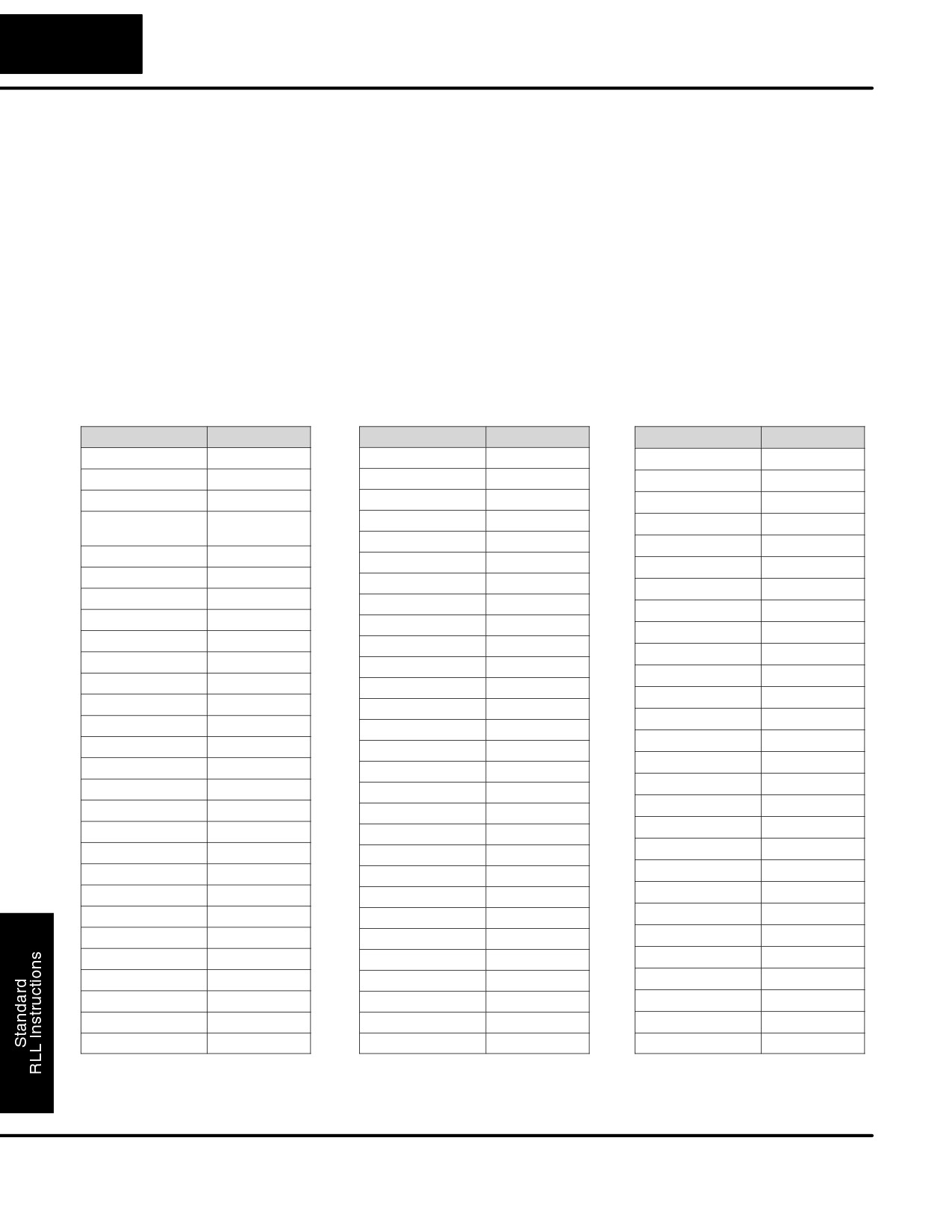
Standard RLL Instructions
5-2
Introduction
DL105 Micro PLCs offer a wide variety of instructions to perform many different
types of operations. This chapter shows you how to use each standard Relay Ladder
Logic (RLL) instruction. In addition to these instructions, you may also need to refer
to the Drum instruction in Chapter 6, or the Stage programming instructions in
Chapter 7.
There are two ways to quickly find the instruction you need.
S
If you know the instruction category (Boolean, Comparative Boolean,
etc.) just use the title at the top of the page to find the pages that
discuss the instructions in that category.
S
If you know the individual instruction name, use the following table to
find the page(s) that discusses the instruction.
Instruction
Page
Instruction
Page
Instruction
Page
ACON
5-83
INV
5-72
PAUSE
5-15
ADD
5-59
IRT
5-79
PD
5-14
ADDD
5-11
ISG
7-20
POP
5-49
AND
5-10,
5-21,
JMP
7-20
RST
5-14
5-51
LD
5-44
RSTI
5-25
AND STR
5-11
LDA
5-47
SET
5-14
ANDD
5-52
LDD
5-45
SETI
5-25
ANDE
5-18
LDF
5-46
SG
7-19
ANDI
5-23
LDLBL
5-74
SGCNT
5-34
ANDN
5-10, 5-21
MLR
5-77
SHFL
5-66
ANDNE
5-18
MLS
5-77
SHFR
5-67
ANDNI
5-23
MOV
5-73
SR
5-38
BCD
5-71
MOVMC
5-74
STOP
5-76
BIN
5-70
MUL
5-63
STR
5-8, 5-19
CMP
5-57
NCON
5-83
STRE
5-16
CMPD
5-58
NOP
5-76
STRI
5-22
CNT
5-32
OR
5-9, 5-20, 5-53
STRN
5-8, 5-19
DECB
5-65
OR OUT
5-13
STRNE
5-16
DECO
5-69
OR OUTI
5-24
STRNI
5-22
DISI
5-79
OR STR
5-11
SUB
5-61
DIV
5-64
ORD
5-54
DLBL
5-83
ORE
5-17
SUBD
5-62
EDRUM
6-2, 6-12
ORI
5-22
TMR
5-27
ENCO
5-68
ORN
5-9, 5-20
TMRF
5-27
END
5-76
ORNE
5-17
TMRA
5-29
ENI
5-79
ORNI
5-22
TMRAF
5-29
FAULT
5-82
OUT
5-13, 5-48
UDC
5-36
INCB
5-65
OUTD
5-48
XOR
5-55
INT
5-79
OUTF
5-49
XORD
5-56
DL105 PLC User Manual, 2nd Edition, Rev. A
Standard RLL Instructions
5-3
Boolean Instructions
Using Boolean Instructions
Do you ever wonder why so many PLC manufacturers always quote the scan time
for a
1K boolean program? Simple. Most all programs utilize many boolean
instructions. These are typically very simple instructions designed to join input and
output contacts in various series and parallel combinations. Since the
DirectSOFT32 software allows you to use graphic symbols to build the program,
you don’t absolutely have to know the mnemonics of the instructions. However, it
may helpful at some point, especially if you ever have to troubleshoot the program
with a Handheld Programmer.The following paragraphs show how these
instructions are used to build simple ladder programs.
All DL105 programs require an END statement as the last instruction. This tells the
END Statement
CPU that this is the end of the program. Normally, any instructions placed after the
END statement will not be executed. There are exceptions to this such as interrupt
routines, etc. Chapter 5 discusses the instruction set in detail.
X0
Y0
OUT
All programs must have
and END statement
END
You use a contact to start rungs that contain both contacts and coils. The boolean
Simple Rungs
instruction that does this is called a Store or, STR instruction. The output point is
represented by the Output or, OUT instruction. The following example shows how to
enter a single contact and a single output coil.
DirectSOFT32 Example
Handheld Mnemonics
STR X0
X0
Y0
OUT Y0
OUT
END
END
Normally Closed Normally closed contacts are also very common. This is accomplished with the
Contact
Store Not or, STRN instruction. The following example shows a simple rung with a
normally closed contact.
DirectSOFT32 Example
Handheld Mnemonics
X0
Y0
STRN X0
OUT Y0
OUT
END
END
DL105 PLC User Manual, 2nd Edition, Rev. A
Standard RLL Instructions
5-4
Boolean Instructions
Use the AND instruction to join two or more contacts in series. The following
Contacts in Series
example shows two contacts in series and a single output coil. The instructions used
would be STR X0, AND X1, followed by OUT Y0.
DirectSOFT32 Example
Handheld Mnemonics
STR X0
X0
X1
Y0
AND X1
OUT
OUT Y0
END
END
Sometimes it is necessary to use midline outputs to get additional outputs that are
Midline Outputs
conditional on other contacts. The following example shows how you can use the
AND instruction to continue a rung with more conditional outputs.
DirectSOFT32 Example
Handheld Mnemonics
STR X0
X0
X1
Y0
AND X1
OUT
OUT Y0
AND X2
X2
Y1
OUT Y1
AND X3
OUT
OUT Y2
END
X3
Y2
OUT
END
Parallel Elements
You also have to join contacts in parallel. The OR instruction allows you to do this.
The following example shows two contacts in parallel and a single output coil. The
instructions would be STR X0, OR X1, followed by OUT Y0.
DirectSOFT32 Example
Handheld Mnemonics
X0
Y0
STR X0
OUT
OR X1
OUT Y0
X1
END
END
DL105 PLC User Manual, 2nd Edition, Rev. A
Standard RLL Instructions
5-5
Boolean Instructions
Joining Series
Quite often it is necessary to join several groups of series elements in parallel. The
Branches in
Or Store (ORSTR) instruction allows this operation. The following example shows a
Parallel
simple network consisting of series elements joined in parallel.
DirectSOFT32 Example
Handheld Mnemonics
X0
X1
Y0
STR X0
OUT
AND X1
STR X2
X2
X3
AND X3
ORSTR
OUT Y0
END
END
Joining Parallel
You can also join one or more parallel branches in series. The And Store (ANDSTR)
Branches in Series
instruction allows this operation. The following example shows a simple network
with contact branches in series with parallel contacts.
DirectSOFT32 Example
Handheld Mnemonics
X0
X1
Y0
STR X0
STR X1
OUT
OR X2
ANDSTR
X2
OUT Y0
END
END
Combination
You can combine the various types of series and parallel branches to solve most any
Networks
application problem. The following example shows a simple combination network.
X0
X2
X5
Y0
OUT
X1
X3
X4
X6
END
Comparative
Some PLC manufacturers make it really difficult to do a simple comparison of two
Boolean
numbers. Some of them require you to move the data all over the place before you
can actually perform the comparison. The DL105 Micro PLCs provide Comparative
Boolean instructions that allow you to quickly and easily solve this problem. The
Comparative Boolean provides evaluation of two 4-digit values using boolean
contacts. The valid evaluations are: equal to, not equal to, equal to or greater than,
and less than.
In the following example when the value
V1400
K1234
Y3
in V-memory location V1400 is equal to
OUT
the constant value
1234, Y3 will
energize.
DL105 PLC User Manual, 2nd Edition, Rev. A
Standard RLL Instructions
5-6
Boolean Instructions
There are limits to how many elements you can include in a rung. This is because the
Boolean Stack
DL105 PLCs use an 8-level boolean stack to evaluate the various logic elements.
The boolean stack is a temporary storage area that solves the logic for the rung.
Each time the program encounters a STR instruction, the instruction is placed on the
top of the stack. Any other STR instructions already on the boolean stack are pushed
down a level. The ANDSTR, and ORSTR instructions combine levels of the boolean
stack when they are encountered. An error will occur during program compilation if
the CPU encounters a rung that uses more than the eight levels of the boolean stack.
The following example shows how the boolean stack is used to solve boolean logic.
X0
X1
ORSTR
AND
X4
Y0
STR
STR
OUT
Output
X2
AND
X3
ANDSTR
STR
X5
OR
STR X0
STR X1
STR X2
AND X3
1
STR X0
1
STR X1
1
STR X2
1
X2 AND X3
2
2
STR X0
2
STR X1
2
STR X1
3
3
3
STR X0
3
STR X0
4
4
4
4
5
5
5
5
6
6
6
6
7
7
7
7
8
8
8
8
ORSTR
AND X4
ORNOT X5
1
X1 OR (X2 AND X3)
1
X4 AND [X1 OR (X2 AND X3)]
1
NOT X5 OR X4 AND [X1 OR (X2 AND X3)]
2
STR X0
2
STR X0
2
STR X0
3
3
3
S
S
S
S
S
S
8
8
8
ANDSTR
1
X0 AND (NOT X5 OR X4) AND [X1 OR (X2 AND X3)]
2
3
S
S
8
DL105 PLC User Manual, 2nd Edition, Rev. A