DL105 Micro PLC. User Manual (2003) - page 5
Standard RLL Instructions
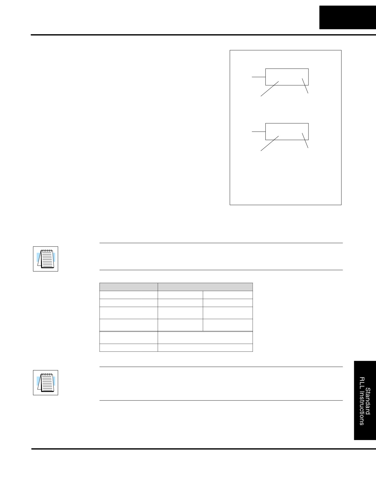
5-7
Boolean Instructions
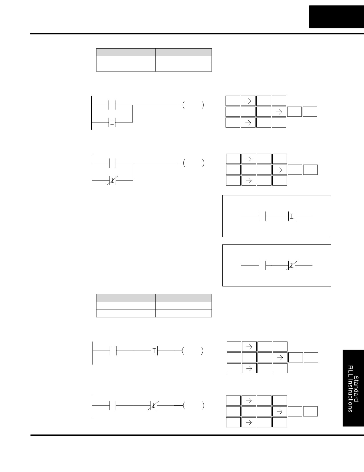
The DL105 Micro PLCs usually can complete an operation cycle in a matter of
Immediate Boolean
milliseconds. However, in some applications you may not be able to wait a few
milliseconds until the next I/O update occurs. The DL105 PLCs offer Immediate
input and outputs which are special boolean instructions that allow reading directly
from inputs and writing directly to outputs during the program execution portion of
the CPU cycle. You may recall that this is normally done during the input or output
update portion of the CPU cycle. The immediate instructions take longer to execute
because the program execution is interrupted while the CPU reads or writes the I/O
point. This function is not normally done until the read inputs or the write outputs
portion of the CPU cycle.
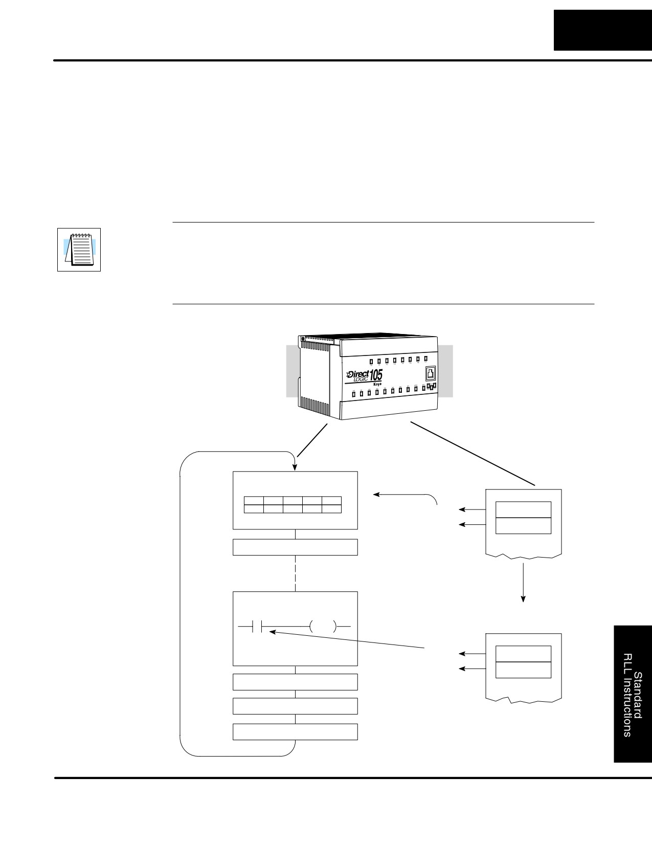
NOTE: Even though the immediate input instruction reads the most current status
from the input point, it only uses the results to solve that one instruction. It does not
use the new status to update the image register. Therefore, any regular instructions
that follow will still use the image register values. Any immediate instructions that
follow will access the I/O again to update the status. The immediate output
instruction will write the status to the I/O and update the image register.
CPU Scan
The CPU reads the inputs from the local
base and stores the status in an input
Read Inputs
image register.
X11
X2
X1
X0
OFF
ON
OFF
OFF
OFF
X0
Input Image Register
OFF
X1
Read Inputs from Specialty I/O
Solve the Application Program
Immediate instruction does not use the
input image register, but instead reads
X0
Y0
the status from the module immediately.
I
I/O Point X0 Changes
ON
X0
OFF
X1
Write Outputs
Write Outputs to Specialty I/O
Diagnostics
DL105 PLC User Manual, 2nd Edition, Rev. A
Standard RLL Instructions
5-8
Boolean Instructions
Boolean Instructions
Store
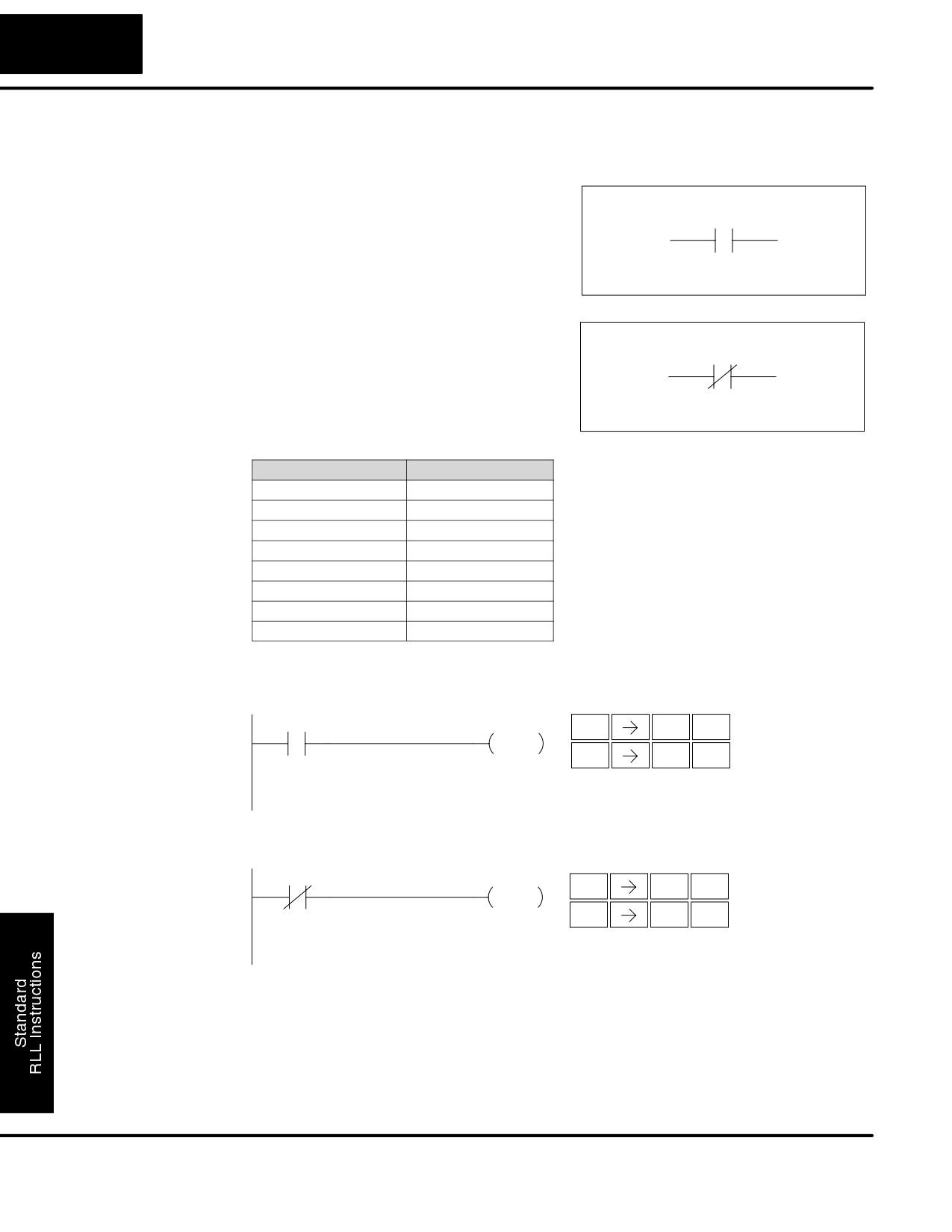
The Store instruction begins a new rung
(STR)
or an additional branch in a rung with a
Aaaa
normally open contact. Status of the
contact will be the same state as the
associated image register point or
memory location.
Store Not
The Store Not instruction begins a new
(STRN)
rung or an additional branch in a rung
Aaaa
with a normally closed contact. Status of
the contact will be opposite the state of
the associated image register point or
memory location.
Operand Data Type
DL130 Range
A
aaa
Inputs
X
0-11
Outputs
Y
0-7
Control Relays
C
0-377
Stage
S
0-377
Timer
T
0-77
Counter
CT
0-77
Special Relay
SP
0-117, 540-577
In the following Store example, when input X1 is on, output Y2 will energize.
DirectSOFT
Handheld Programmer Keystrokes
X1
Y2
$
B
ENT
STR
1
OUT
GX
C
ENT
OUT
2
In the following Store Not example, when input X1 is off output Y2 will energize.
DirectSOFT
Handheld Programmer Keystrokes
X1
Y2
SP
B
ENT
STRN
1
OUT
GX
C
ENT
OUT
2
DL105 PLC User Manual, 2nd Edition, Rev. A
Standard RLL Instructions
5-9
Boolean Instructions
Or
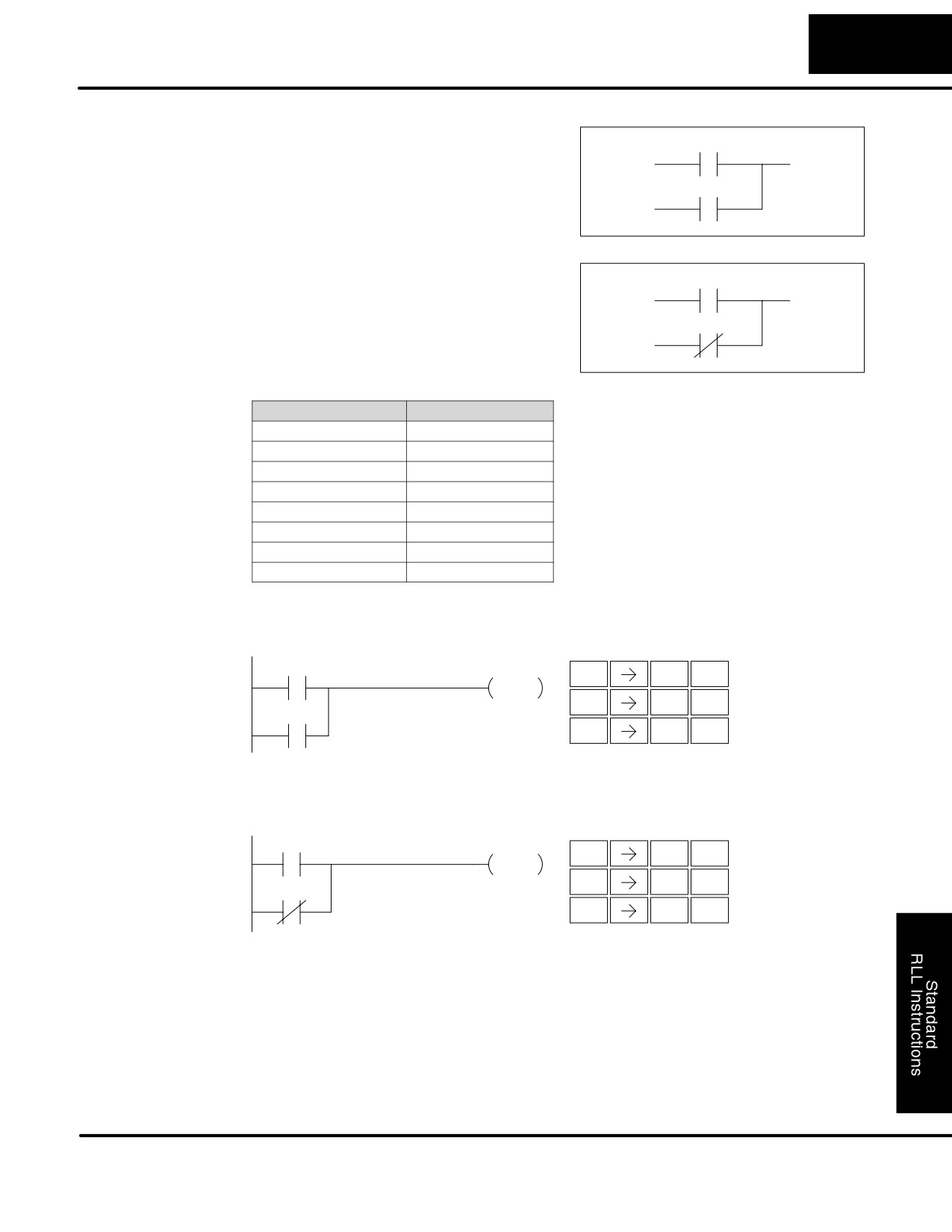
The Or instruction logically ors a normally
(OR)
open contact in parallel with another
contact in a rung. The status of the
Aaaa
contact will be the same state as the
associated image register point or
memory location.
Or Not
The Or Not instruction logically ors a
(ORN)
normally closed contact in parallel with
another contact in a rung. The status of
Aaaa
the contact will be opposite the state of
the associated image register point or
memory location.
Operand Data Type
DL130 Range
A
aaa
Inputs
X
0-11
Outputs
Y
0-7
Control Relays
C
0-377
Stage
S
0-377
Timer
T
0-77
Counter
CT
0-77
Special Relay
SP
0-117, 540-577
In the following Or example, when input X1 or X2 is on, output Y5 will energize.
DirectSOFT
Handheld Programmer Keystrokes
X1
Y5
$
B
ENT
STR
1
OUT
Q
C
ENT
OR
2
X2
GX
F
ENT
OUT
5
In the following Or Not example, when input X1 is on or X2 is off, output Y5 will
energize.
DirectSOFT
Handheld Programmer Keystrokes
X1
Y5
$
B
ENT
STR
1
OUT
R
C
ENT
ORN
2
X2
GX
F
ENT
OUT
5
DL105 PLC User Manual, 2nd Edition, Rev. A
Standard RLL Instructions
5-10
Boolean Instructions
And
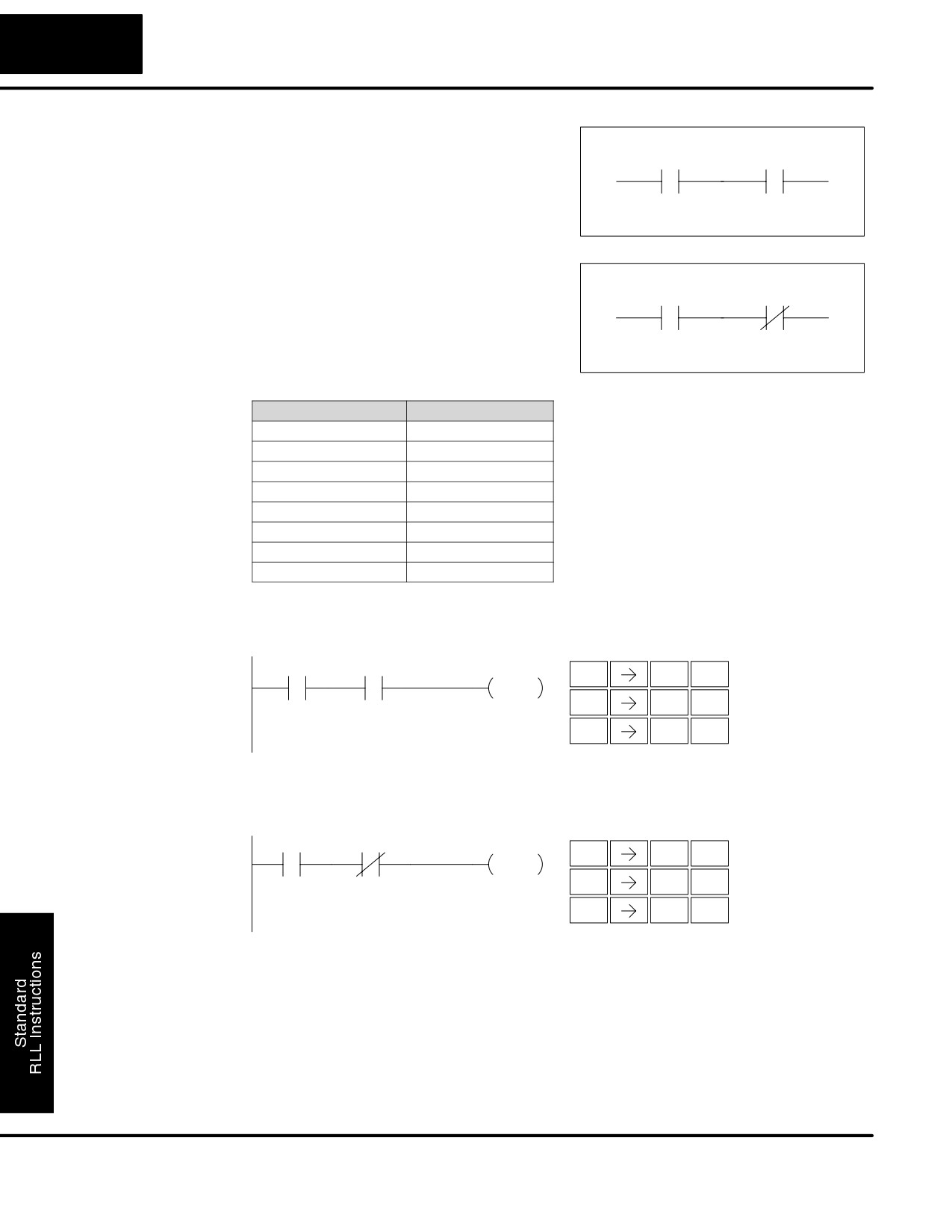
The And instruction logically ands a
(AND)
normally open contact in series with
Aaaa
another contact in a rung. The status of
the contact will be the same state as the
associated image register point or
memory location.
And Not
The And Not instruction logically ands a
(ANDN)
normally closed contact in series with
Aaaa
another contact in a rung. The status of
the contact will be opposite the state of
the associated image register point or
memory location.
Operand Data Type
DL130 Range
A
aaa
Inputs
X
0-11
Outputs
Y
0-7
Control Relays
C
0-377
Stage
S
0-377
Timer
T
0-77
Counter
CT
0-77
Special Relay
SP
0-117, 540-577
In the following And example, when input X1 and X2 are on output Y5 will energize.
DirectSOFT
Handheld Programmer Keystrokes
X1
X2
Y5
$
B
ENT
STR
1
OUT
V
C
ENT
AND
2
GX
F
ENT
OUT
5
In the following And Not example, when input X1 is on and X2 is off output Y5 will
energize.
DirectSOFT
Handheld Programmer Keystrokes
X1
X2
Y5
$
B
ENT
STR
1
OUT
W
C
ENT
ANDN
2
GX
F
ENT
OUT
5
DL105 PLC User Manual, 2nd Edition, Rev. A
Standard RLL Instructions
5-11
Boolean Instructions
And Store
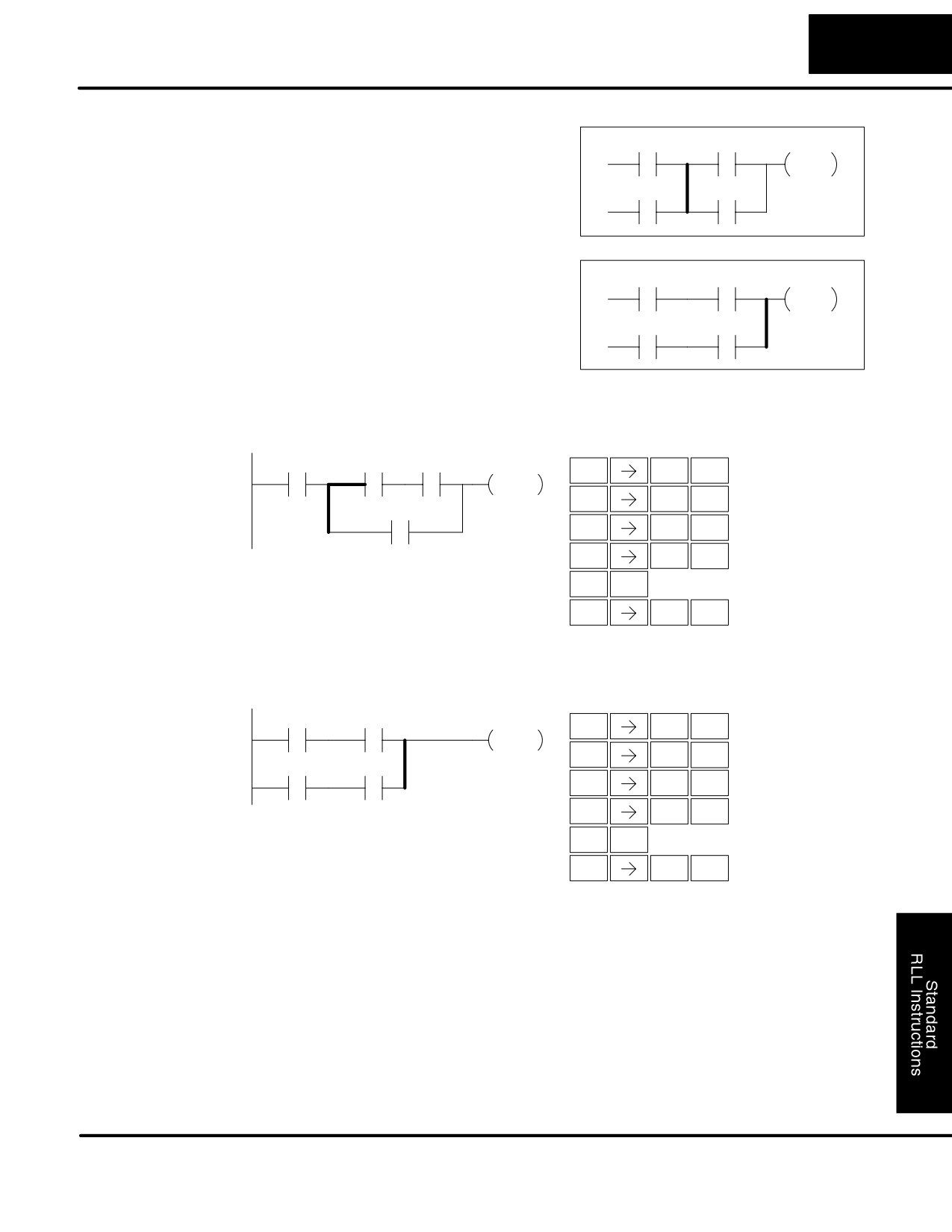
The And Store instruction logically ands
(AND STR)
two branches of a rung in series. Both
OUT
branches must begin with the Store
À
Á
instruction.
Or Store
The Or Store instruction logically ors two
À
(OR STR)
branches of a rung in parallel. Both
OUT
branches must begin with the Store
instruction.
Á
In the following And Store example, the branch consisting of contacts X2, X3, and X4
have been anded with the branch consisting of contact X1.
DirectSOFT
Handheld Programmer Keystrokes
X1
X2
X3
Y5
$
B
ENT
STR
1
OUT
$
C
ENT
STR
2
X4
V
D
ENT
AND
3
Q
E
ENT
OR
4
L
ENT
ANDST
GX
F
ENT
OUT
5
In the following Or Store example, the branch consisting of X1 and X2 have been
ored with the branch consisting of X3 and X4.
DirectSOFT
Handheld Programmer Keystrokes
X1
X2
Y5
$
B
ENT
STR
1
OUT
V
C
ENT
AND
2
X3
X4
$
D
ENT
STR
3
V
E
ENT
AND
4
M
ENT
ORST
GX
F
ENT
OUT
5
DL105 PLC User Manual, 2nd Edition, Rev. A
Standard RLL Instructions
5-12
Boolean Instructions
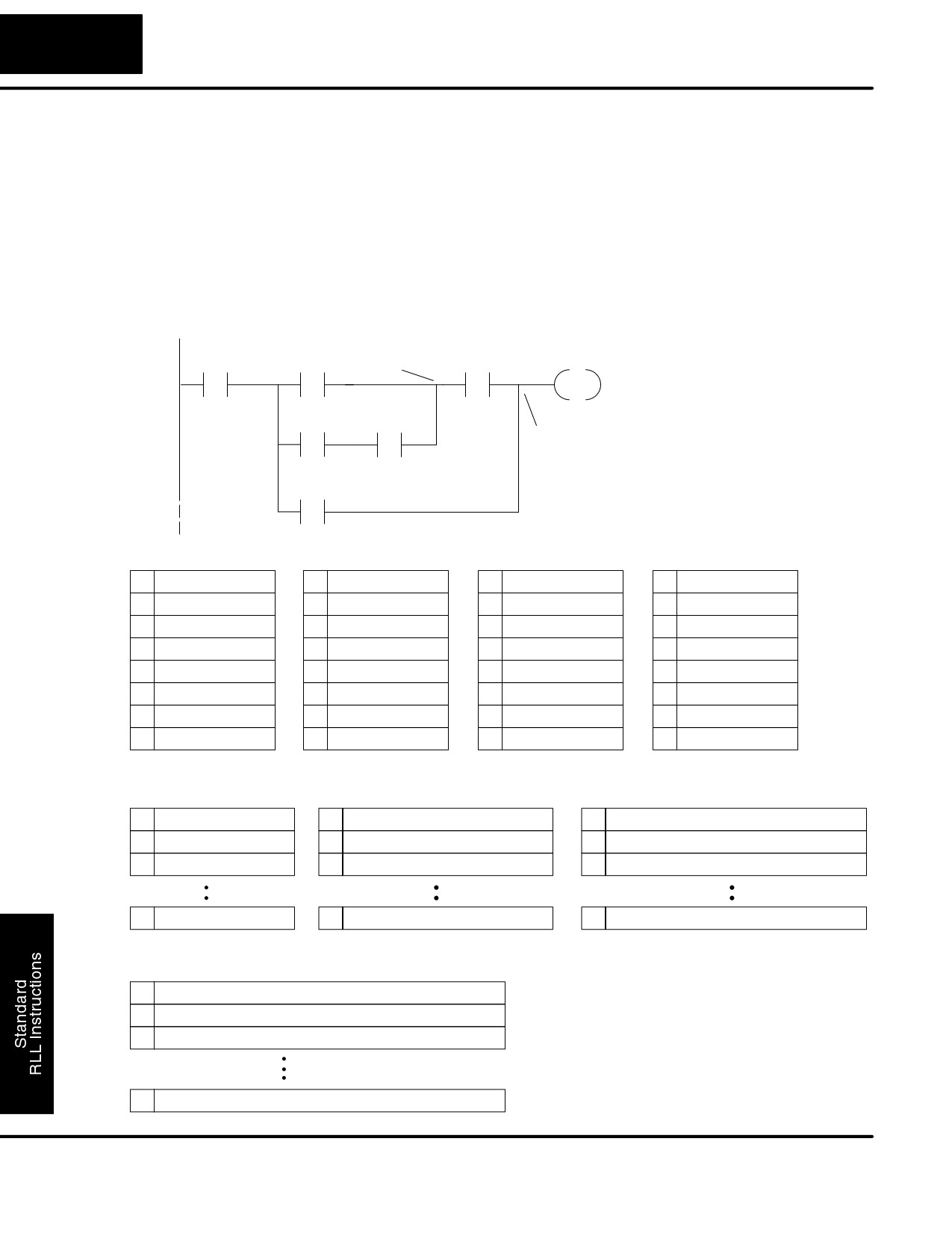
There are limits to what you can enter with boolean instructions. This is because the
DL105 internal CPU uses an 8-level stack to evaluate the various logic elements.
The stack is a temporary storage area that helps solve the logic for the rung. Each
time you enter a STR instruction, the instruction is placed on the top of the stack. Any
other instructions on the stack are pushed down a level. The And Store and Or Store
instructions combine levels of the stack when they are encountered. Since the stack
is only eight levels, an error will occur if the CPU encounters a rung that uses more
than the eight levels of the stack.
The following example shows how the stack is used to solve boolean logic.
X0
X1
ORST
AND
X4
Y5
STR
STR
OUT
Output
X2
AND
X3
ANDST
STR
X5
OR
STR X0
STR X1
STR X2
AND X3
1
STR X0
1
STR X1
1
STR X2
1
X2 AND X3
2
2
STR X0
2
STR X1
2
STR X1
3
3
3
STR X0
3
STR X0
4
4
4
4
5
5
5
5
6
6
6
6
7
7
7
7
8
8
8
8
ORST
AND X4
OR X5
1
X1 OR (X2 AND X3)
1
X4 AND [X1 OR (X2 AND X3)]
1
X5 OR [X4 AND [X1 OR (X2 AND X3)]]
2
STR X0
2
STR X0
2
STR X0
3
3
3
8
8
8
ANDST
1
X0 AND [(X5 OR [X4) AND [X1 OR (X2 AND X3)]]]
2
3
8
DL105 PLC User Manual, 2nd Edition, Rev. A
Standard RLL Instructions
5-13
Boolean Instructions
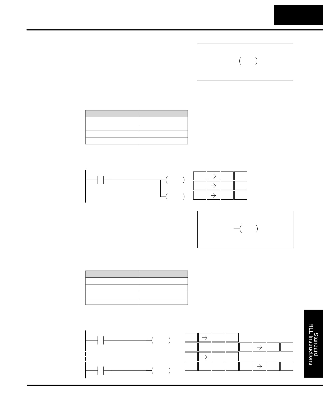
Out
The Out instruction reflects the status of
(OUT)
the rung (on/off) and outputs the discrete
Aaaa
(on/off) state to the specified image
OUT
register point or memory location.
Multiple Out instructions referencing the same discrete location should not be used
since only the last Out instruction in the program will control the physical output
point. Instead, use the next instruction, the Or Out.
Operand Data Type
DL130 Range
A
aaa
Inputs
X
0-11
Outputs
Y
0-7
Control Relays
C
0-377
In the following Out example, when input X1 is on, output Y2 and Y5 will energize.
DirectSOFT
Handheld Programmer Keystrokes
X1
Y2
$
B
ENT
STR
1
OUT
GX
C
ENT
OUT
2
Y5
GX
F
OUT
OUT
5
ENT
Or Out
The Or Out instruction allows more than
(OR OUT)
one rung of discrete logic to control a
A aaa
single output. Multiple Or Out
OR OUT
instructions referencing the same output
coil may be used, since all contacts
controlling the output are logically ORed
together. If the status of any rung is on,
the output will also be on.
Operand Data Type
DL130 Range
A
aaa
Inputs
X
0-177
Outputs
Y
0-177
Control Relays
C
0-377
In the following example, when X1 or X4 is on, Y2 will energize.
DirectSOFT
Handheld Programmer Keystrokes
X1
Y2
$
B
ENT
OR OUT
STR
1
O
D
F
C
ENT
ENT
ENT
INST#
3
5
2
$
E
ENT
STR
4
X4
Y2
O
D
F
C
ENT
ENT
ENT
INST#
3
5
2
OR OUT
DL105 PLC User Manual, 2nd Edition, Rev. A
Standard RLL Instructions
5-14
Boolean Instructions
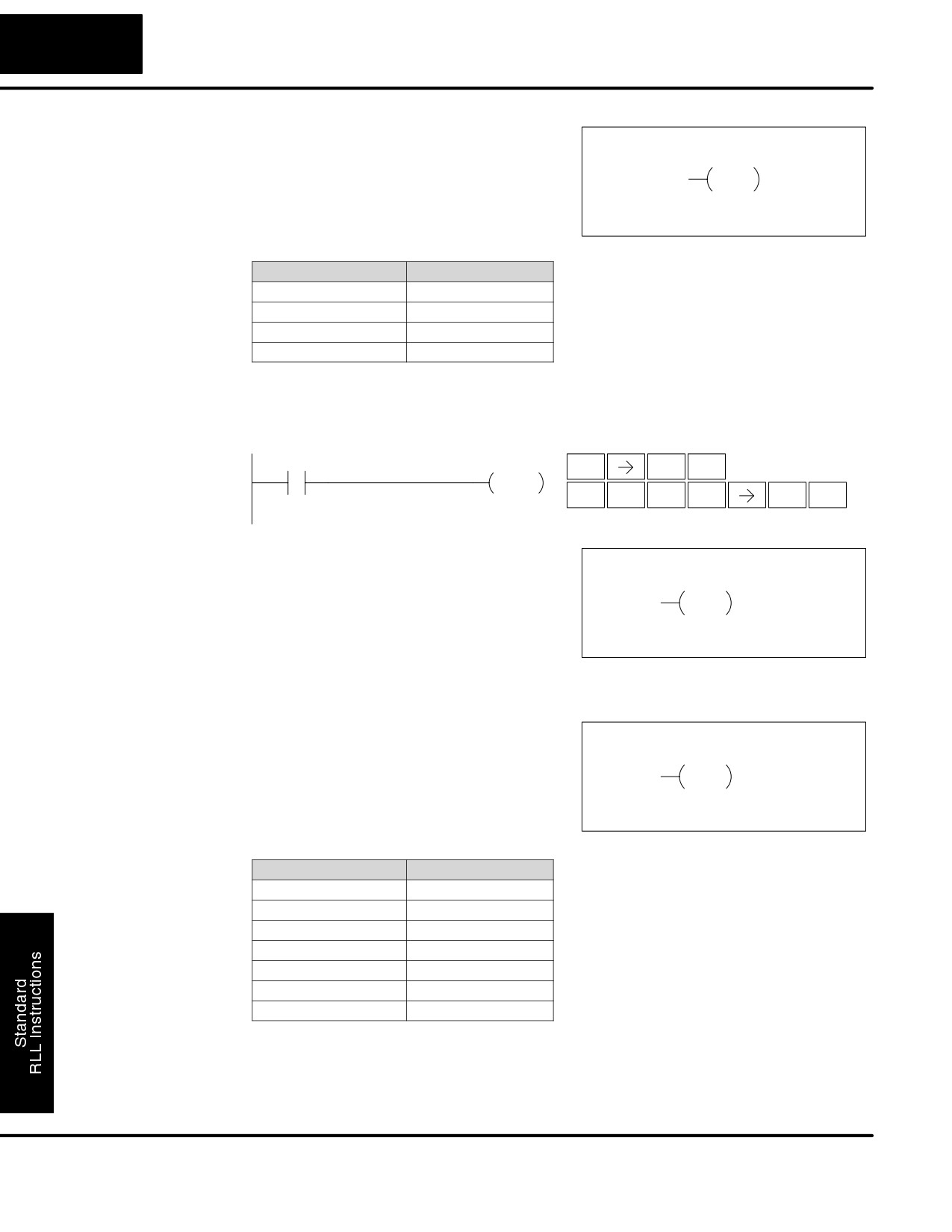
Positive
The Positive Differential instruction is
Differential
typically known as a one shot. When the
A aaa
(PD)
input logic produces an off to on
PD
transition, the output will energize for one
CPU scan.
Operand Data Type
DL130 Range
A
aaa
Inputs
X
0-11
Outputs
Y
0-7
Control Relays
C
0-377
In the following example, every time X1 makes an off to on transition, C0 will
energize for one scan.
DirectSOFT
Handheld Programmer Keystrokes
X1
C0
$
B
ENT
STR
1
PD
P
D
A
SHFT
SHFT
ENT
CV
3
0
Set
Optional
The Set instruction sets or turns on an
memory range
(SET)
image register point/memory location or
A aaa
aaa
a consecutive range of image register
SET
points/memory locations. Once the
point/location is set it will remain on until it
is reset using the Reset instruction. It is
not necessary for the input controlling the
Set instruction to remain on.
Reset
The Reset instruction resets or turns off
Optional
memory range
(RST)
an image register point/memory location
A aaa
aaa
or a range of image registers
RST
points/memory locations. Once the
point/location is reset it is not necessary
for the input to remain on.
Operand Data Type
DL105 Range
A
aaa
Inputs
X
0-11
Outputs
Y
0-7
Control Relays
C
0-377
Stage
S
0-377
Timer
T
0-77
Counter
CT
0-77
DL105 PLC User Manual, 2nd Edition, Rev. A
Standard RLL Instructions
5-15
Boolean Instructions
Set, Reset Instr.
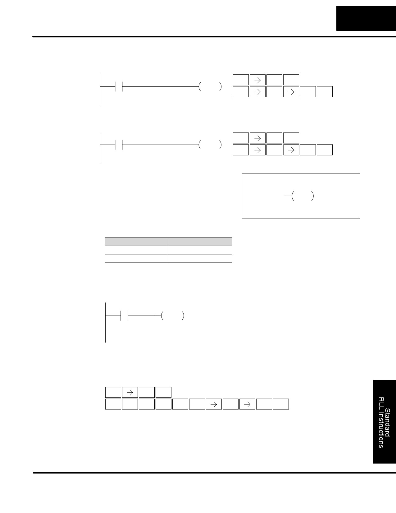
In the following example when X1 is on, Y2 through Y5 will energize.
Continued
DirectSOFT
Handheld Programmer Keystrokes
X1
$
B
Y2
Y5
ENT
STR
1
SET
X
C
F
ENT
SET
2
5
In the following example when X1 is on, Y2 through Y5 will be reset or de-energized.
DirectSOFT
Handheld Programmer Keystrokes
X1
$
B
Y2
Y5
ENT
STR
1
RST
S
C
F
ENT
RST
2
5
Pause
The Pause instruction disables the
(PAUSE)
output update on a range of outputs. The
Y aaa aaa
ladder program will continue to run and
PAUSE
update the image register. However, the
outputs in the range specified in the
Pause instruction will be turned off at the
output points.
Operand Data Type
DL130 Range
aaa
Outputs
Y
0-7
In the following example, when X1 is ON, Y5-Y7 will be turned OFF. The execution of
the ladder program will not be affected.
DirectSOFT
X1
Y5
Y7
PAUSE
Since the D2-HPP Handheld Programmer does not have a specific Pause key, you
can use the corresponding instruction number for entry (#960), or type each letter of
the command.
Handheld Programmer Keystrokes
$
B
ENT
STR
1
O
J
G
A
ENT
ENT
F
H
ENT
INST#
9
6
0
5
7
In some cases, you may want certain output points in the specified pause range to
operate normally. In that case, use Aux 58 to over-ride the Pause instruction.
DL105 PLC User Manual, 2nd Edition, Rev. A
Standard RLL Instructions
5-16
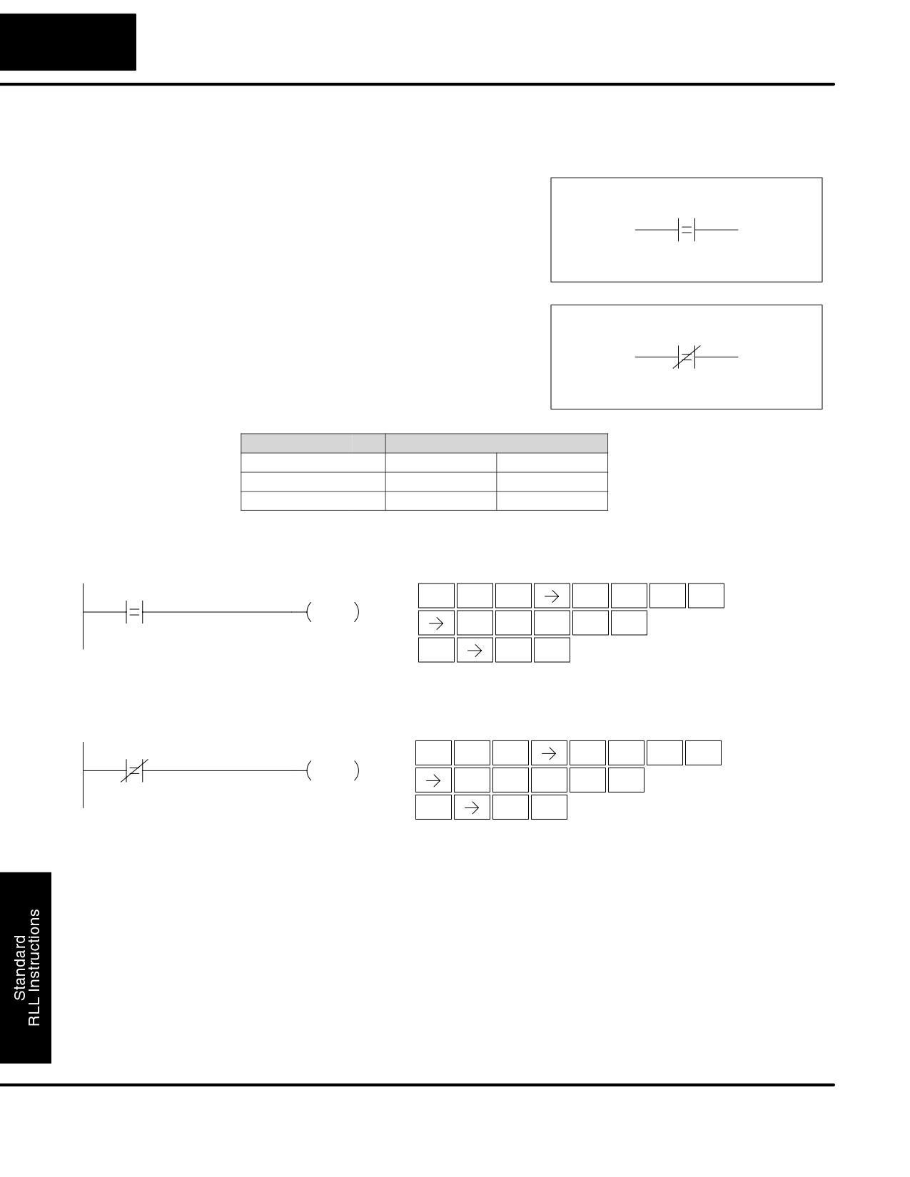
Comparative Boolean Instructions
Comparative Boolean
Store If Equal
The Store If Equal instruction begins a
(STRE)
new rung or additional branch in a rung
V aaa
B bbb
with a normally open comparative
contact. The contact will be on when
Vaaa =Bbbb .
Store If Not Equal
The Store If Not Equal instruction begins
(STRNE)
a new rung or additional branch in a rung
V aaa
B bbb
with a normally closed comparative
contact. The contact will be on when
Vaaa Bbbb.
Operand Data Type
DL130 Range
B
aaa
bbb
V memory
V
All (See page 4-28)
All (See page 4-28)
Constant
K
--
0-FFFF
In the following example, when the value in V memory location V2000 = 4933 , Y3 will
energize.
DirectSOFT32
Handheld Programmer Keystrokes
V2000
K4933
Y3
$
SHFT
E
C
A
A
A
STR
4
2
0
0
0
OUT
E
J
D
D
ENT
4
9
3
3
GX
D
ENT
OUT
3
In the following example, when the value in V memory location V2000
5060, Y3
will energize.
DirectSOFT32
Handheld Programmer Keystrokes
SP
E
C
A
A
A
V2000
K5060
Y3
SHFT
STRN
4
2
0
0
0
OUT
F
A
G
A
ENT
5
0
6
0
GX
D
ENT
OUT
3
DL105 PLC User Manual, 2nd Edition, Rev. A
Standard RLL Instructions
5-17
Comparative Boolean Instructions
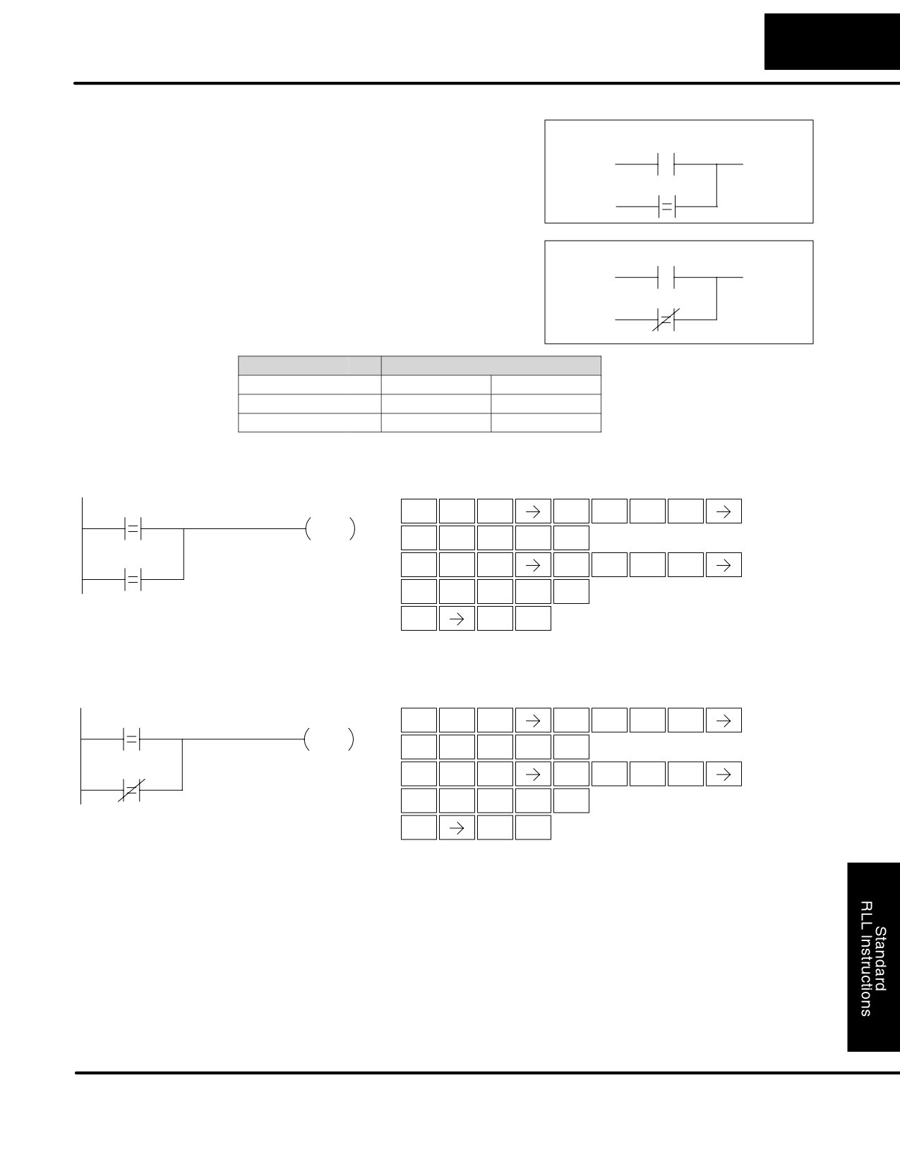
Or If Equal
The Or If Equal instruction connects a
(ORE)
normally open comparative contact in
parallel with another contact. The
contact will be on when Vaaa = Bbbb.
V aaa
B bbb
Or If Not Equal
The Or If Not Equal instruction connects
(ORNE)
a normally closed comparative contact in
parallel with another contact. The
contact will be on when Vaaa Bbbb.
V aaa
B bbb
Operand Data Type
DL130 Range
B
aaa
bbb
V memory
V
All (See page 4-28)
All (See page 4-28)
Constant
K
--
0-FFFF
In the following example, when the value in V memory location V2000 = 4500 or
V2002 = 2345 , Y3 will energize.
DirectSOFT32
Handheld Programmer Keystrokes
$
E
C
A
A
A
V2000
K4500
Y3
SHFT
STR
4
2
0
0
0
OUT
E
F
A
A
ENT
4
5
0
0
V2002
K2345
Q
E
C
A
A
C
SHFT
OR
4
2
0
0
2
C
D
E
F
ENT
2
3
4
5
GX
D
ENT
OUT
3
In the following example, when the value in V memory location V2000 = 3916 or
V2002
2500, Y3 will energize.
DirectSOFT32
Handheld Programmer Keystrokes
$
E
C
A
A
A
V2000
K3916
Y3
SHFT
STR
4
2
0
0
0
OUT
D
J
B
G
ENT
3
9
1
6
R
E
C
A
A
C
V2002
K2500
SHFT
ORN
4
2
0
0
2
C
F
A
A
ENT
2
5
0
0
GX
D
ENT
OUT
3
DL105 PLC User Manual, 2nd Edition, Rev. A
Standard RLL Instructions
5-18
Comparative Boolean Instructions
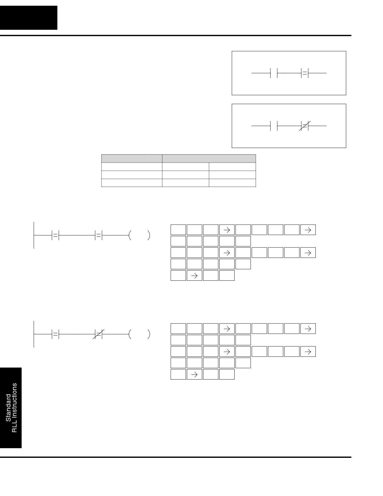
And If Equal
The And If Equal instruction connects a
(ANDE)
normally open comparative contact in
V aaa
B bbb
series with another contact. The contact
will be on when Vaaa = Bbbb.
And If Not Equal
The And If Not Equal instruction connects
(ANDNE)
a normally closed comparative contact in
V aaa
B bbb
series with another contact. The contact
will be on when Vaaa Bbbb
Operand Data Type
DL130 Range
A/B
aaa
bbb
V memory
V
All (See page 4-28)
All (See page 4-28)
Constant
K
--
0-FFFF
In the following example, when the value in V memory location V2000 = 5000 and
V2002 = 2345, Y3 will energize.
DirectSOFT32
Handheld Programmer Keystrokes
V2000
K5000
V2002
K2345
Y3
$
E
C
A
A
A
SHFT
STR
4
2
0
0
0
OUT
F
A
A
A
ENT
5
0
0
0
V
E
C
A
A
C
SHFT
AND
4
2
0
0
2
C
D
E
F
ENT
2
3
4
5
GX
D
ENT
OUT
3
In the following example, when the value in V memory location V2000 = 2550 and
V2002
2500, Y3 will energize.
DirectSOFT32
Handheld Programmer Keystrokes
V2000
K2550
V2002
K2500
Y3
$
E
C
A
A
A
SHFT
STR
4
2
0
0
0
OUT
C
F
F
A
ENT
2
5
5
0
W
E
C
A
A
C
SHFT
ANDN
4
2
0
0
2
C
F
A
A
ENT
2
5
0
0
GX
D
ENT
OUT
3
DL105 PLC User Manual, 2nd Edition, Rev. A
Standard RLL Instructions
5-19
Comparative Boolean Instructions
Store
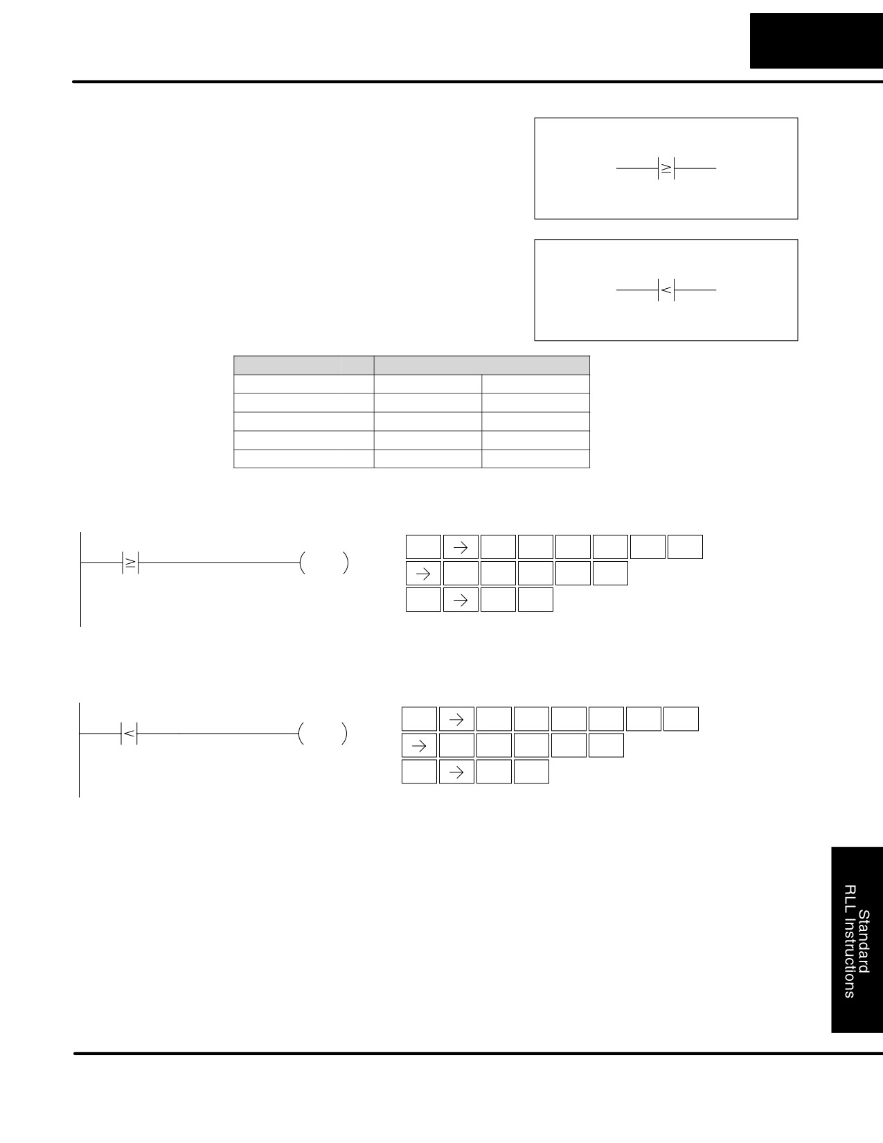
The Comparative Store instruction
(STR)
begins a new rung or additional branch in
A aaa B bbb
a rung with a normally open comparative
contact. The contact will be on when
Aaaa Bbbb.
Store Not
The Comparative Store Not instruction
(STRN)
begins a new rung or additional branch in
A aaa B bbb
a rung with a normally closed
comparative contact. The contact will be
on when Aaaa < Bbbb.
Operand Data Type
DL130 Range
A/B
aaa
bbb
V memory
V
All (See page 4-28)
All (See page 4-28)
Constant
K
--
0-FFFF
Timer
T
0-77
Counter
CT
0-77
In the following example, when the value in V memory location V2000
1000, Y3
will energize.
DirectSOFT32
Handheld Programmer Keystrokes
$
V
C
A
A
A
V2000
K1000
Y3
SHFT
STR
AND
2
0
0
0
OUT
B
A
A
A
ENT
1
0
0
0
GX
D
ENT
OUT
3
In the following example, when the value in V memory location V2000 < 4050, Y3 will
energize.
DirectSOFT32
Handheld Programmer Keystrokes
V2000
K4050
Y3
SP
V
C
A
A
A
SHFT
STRN
AND
2
0
0
0
OUT
E
A
F
A
ENT
4
0
5
0
GX
D
ENT
OUT
3
DL105 PLC User Manual, 2nd Edition, Rev. A
Standard RLL Instructions
5-20
Comparative Boolean Instructions
Or
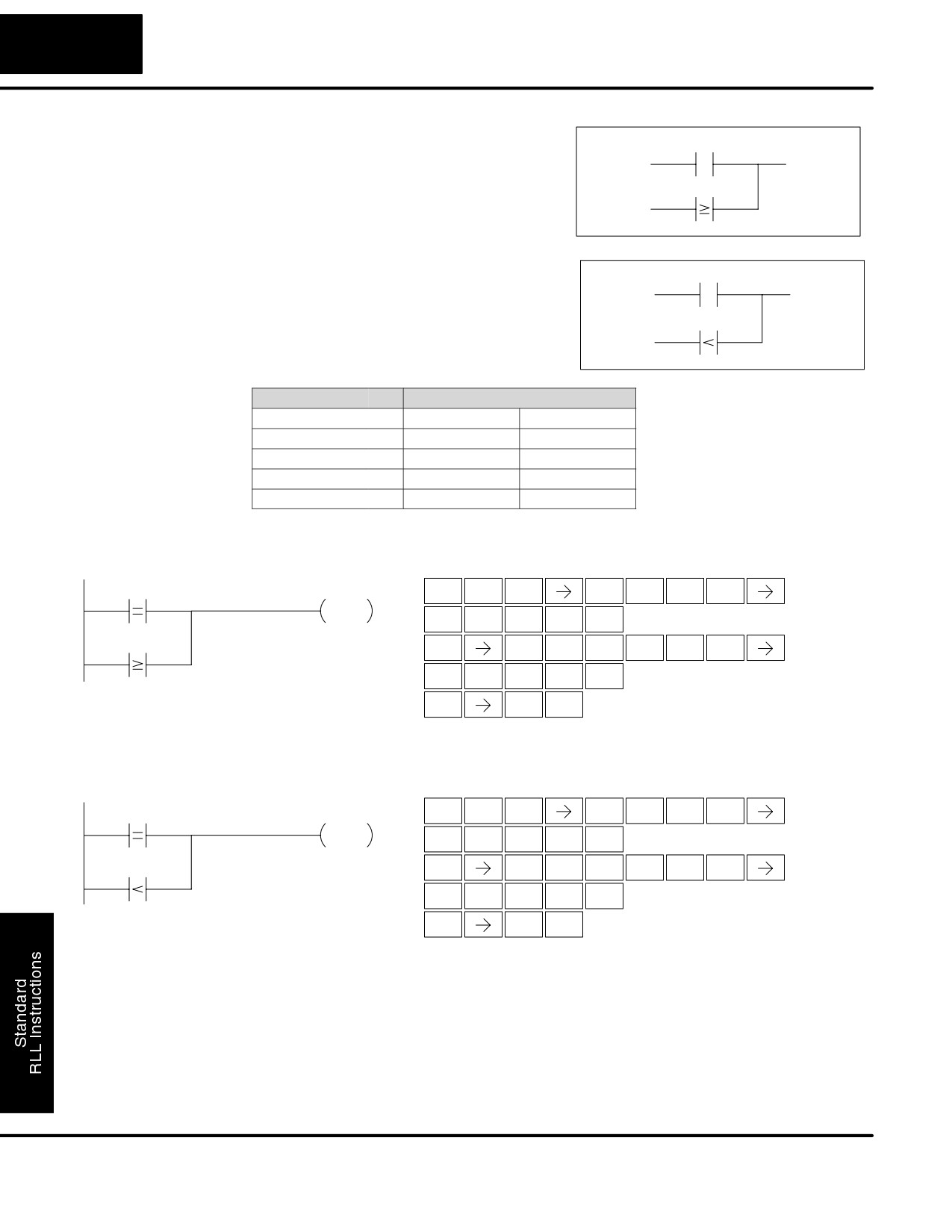
The Comparative Or instruction
(OR)
connects a normally open comparative
contact in parallel with another contact.
The contact will be on when Aaaa
A aaa B bbb
Bbbb.
Or Not
The Comparative Or Not instruction
(ORN)
connects a normally open comparative
contact in parallel with another contact.
A aaa B bbb
The contact will be on when Aaaa < Bbbb.
Operand Data Type
DL130 Range
A/B
aaa
bbb
V memory
V
All (See page 4-28)
All (See page 4-28)
Constant
K
--
0-FFFF
Timer
T
0-77
Counter
CT
0-77
In the following example, when the value in V memory location V2000 = 6045 or
V2002
2345, Y3 will energize.
DirectSOFT32
Handheld Programmer Keystrokes
$
E
C
A
A
A
V2000
K6045
Y3
SHFT
STR
4
2
0
0
0
OUT
G
A
E
F
ENT
6
0
4
5
Q
V
C
A
A
C
V2002
K2345
SHFT
OR
AND
2
0
0
2
C
D
E
F
ENT
2
3
4
5
GX
D
ENT
OUT
3
In the following example when the value in V memory location V2000 = 1000 or
V2002 < 2500, Y3 will energize.
DirectSOFT32
Handheld Programmer Keystrokes
$
E
C
A
A
A
SHFT
V2000
K1000
Y3
STR
4
2
0
0
0
OUT
B
A
A
A
ENT
1
0
0
0
R
V
C
A
A
C
SHFT
V2002
K2500
ORN
AND
2
0
0
2
C
F
A
A
ENT
2
5
0
0
GX
D
ENT
OUT
3
DL105 PLC User Manual, 2nd Edition, Rev. A
Standard RLL Instructions
5-21
Comparative Boolean Instructions
And
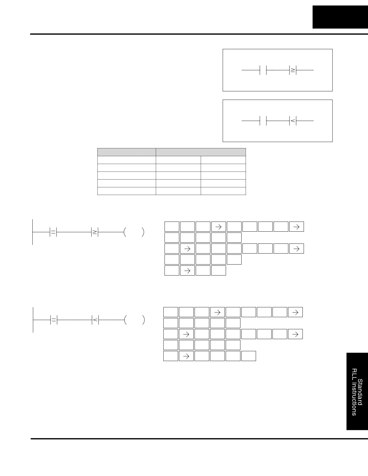
The Comparative And instruction
(AND)
connects a normally open comparative
A aaa B bbb
contact in series with another contact.
The contact will be on when Aaaa
Bbbb.
And Not
The Comparative And Not instruction
(ANDN)
connects a normally open comparative
A aaa B bbb
contact in parallel with another contact.
The contact will be on when Aaaa <
Bbbb.
Operand Data Type
DL130 Range
A/B
aaa
bbb
V memory
V
All (See page 4-28)
All (See page 4-28)
Constant
K
--
0-FFFF
Timer
T
0-77
Counter
CT
0-77
In the following example, when the value in V memory location V2000 = 5000, and
V2002
2345, Y3 will energize.
DirectSOFT32
Handheld Programmer Keystrokes
V2000
K5000
V2002
K2345
Y3
$
E
C
A
A
A
SHFT
STR
4
2
0
0
0
OUT
F
A
A
A
ENT
5
0
0
0
V
V
C
A
A
C
SHFT
AND
AND
2
0
0
2
C
D
E
F
ENT
2
3
4
5
GX
D
ENT
OUT
3
In the following example, when the value in V memory location V2000 = 7000 and
V2002 < 2500, Y3 will energize.
DirectSOFT32
Handheld Programmer Keystrokes
$
E
C
A
A
A
V2000
K7000
V2002
K2500
Y3
SHFT
STR
4
2
0
0
0
OUT
H
A
A
A
ENT
7
0
0
0
W
SHFT
V
C
A
A
C
ANDN
AND
2
0
0
2
C
F
A
A
ENT
2
5
0
0
GX
Y
D
SHFT
ENT
OUT
AND
3
DL105 PLC User Manual, 2nd Edition, Rev. A
Standard RLL Instructions
5-22
Immediate Instructions
Immediate Instructions
Store
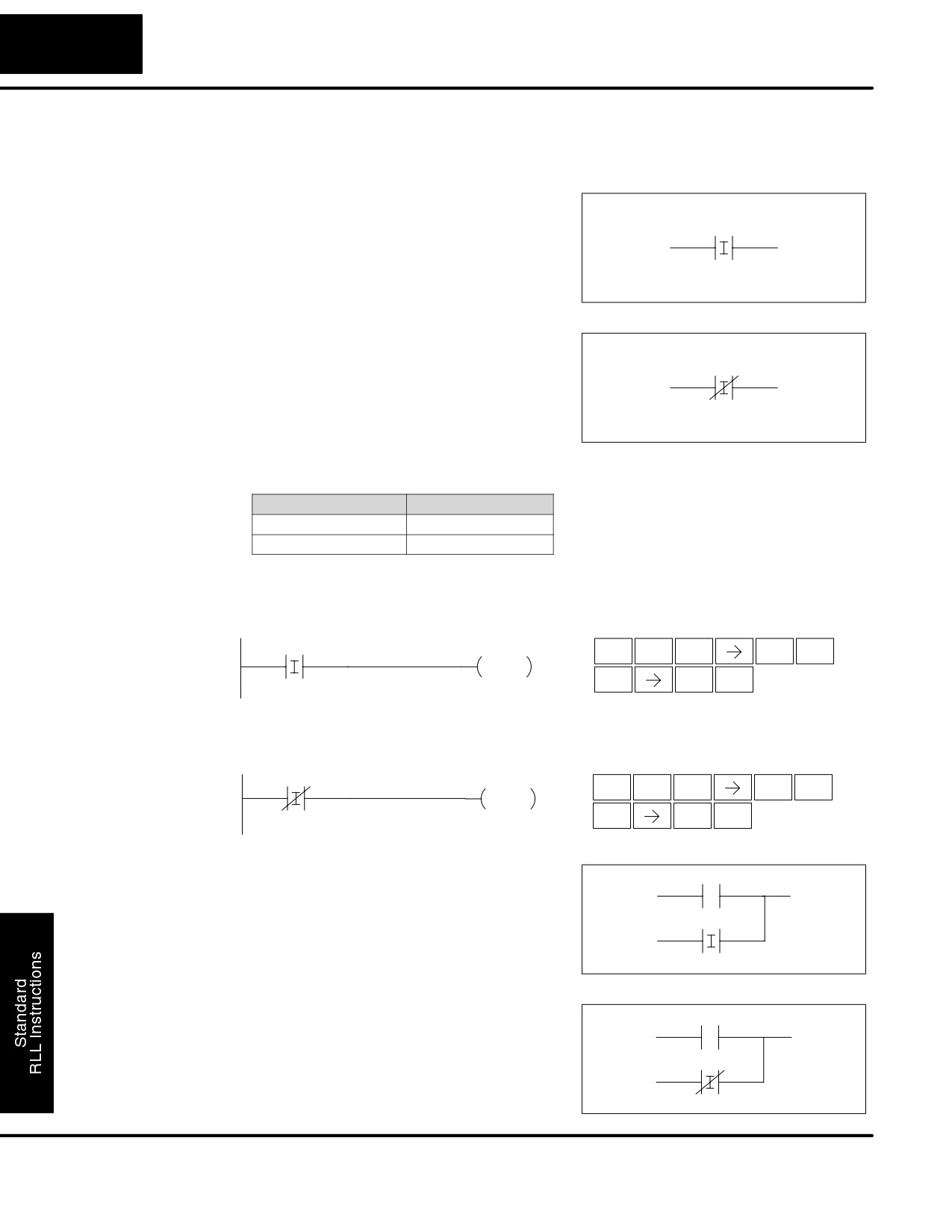
The Store Immediate instruction begins a
Immediate
new rung or additional branch in a rung.
X aaa
(STRI)
The status of the contact will be the same
as the status of the associated input point
at the time the instruction is executed. The
image register is not updated.
Store Not
The Store Not Immediate instruction
Immediate
begins a new rung or additional branch in
X aaa
(STRNI)
a rung. The status of the contact will be
opposite the status of the associated input
point at the time the instruction is
executed. The image register is not
updated.
Operand Data Type
DL130 Range
aaa
Inputs
X
0-11
In the following example, when X1 is on, Y2 will energize.
DirectSOFT32
Handheld Programmer Keystrokes
Y2
$
I
B
X1
SHFT
ENT
STR
8
1
OUT
GX
C
ENT
OUT
2
In the following example when X1 is off, Y2 will energize.
DirectSOFT32
Handheld Programmer Keystrokes
X1
Y2
SP
I
B
SHFT
ENT
STRN
8
1
OUT
GX
C
ENT
OUT
2
Or Immediate
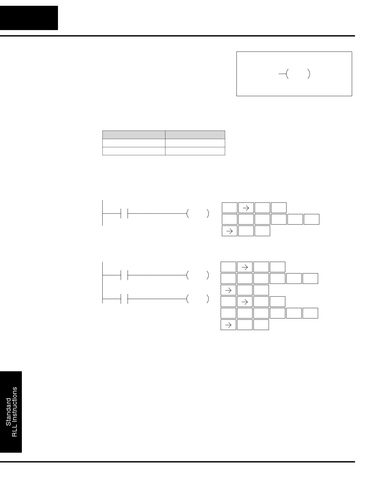
The Or Immediate connects two contacts
(ORI)
in parallel. The status of the contact will be
the same as the status of the associated
X aaa
input point at the time the instruction is
executed. The image register is not
updated.
Or Not Immediate
The Or Not Immediate connects two
(ORNI)
contacts in parallel. The status of the
contact will be opposite the status of the
X aaa
associated input point at the time the
instruction is executed. The image
register is not updated.
DL105 PLC User Manual, 2nd Edition, Rev. A
Standard RLL Instructions
5-23
Immediate Instructions
OR Immediate
Operand Data Type
DL130 Range
Instructions Cont’d
aaa
Inputs
X
0-177
In the following example, when X1 or X2 is on, Y5 will energize.
DirectSOFT32
Handheld Programmer Keystrokes
X1
Y5
$
B
ENT
STR
1
OUT
Q
I
C
SHFT
ENT
OR
8
2
X2
GX
F
ENT
OUT
5
In the following example, when X1 is on or X2 is off, Y5 will energize.
Handheld Programmer Keystrokes
DirectSOFT32
X1
Y5
$
B
ENT
STR
1
OUT
R
SHFT
I
C
ENT
ORN
8
2
X2
GX
F
ENT
OUT
5
And Immediate
The And Immediate connects two
(ANDI)
contacts in series. The status of the
X aaa
contact will be the same as the status of
the associated input point at the time the
instruction is executed. The image
register is not updated.
And Not Immediate The And Not Immediate connects two
(ANDNI)
contacts in series. The status of the
X aaa
contact will be opposite the status of the
associated input point at the time the
instruction is executed. The image
register is not updated.
Operand Data Type
DL130 Range
aaa
Inputs
X
0-11
In the following example, when X1 and X2 are on, Y5 will energize.
DirectSOFT
Handheld Programmer Keystrokes
X1
X2
Y5
$
B
ENT
STR
1
OUT
V
I
C
SHFT
ENT
AND
8
2
GX
F
ENT
OUT
5
In the following example, when X1 is on and X2 are off, Y5 will energize.
DirectSOFT
Handheld Programmer Keystrokes
X1
X2
Y5
$
B
ENT
STR
1
OUT
W
I
C
SHFT
ENT
ANDN
8
2
GX
F
ENT
OUT
5
DL105 PLC User Manual, 2nd Edition, Rev. A
Standard RLL Instructions
5-24
Immediate Instructions
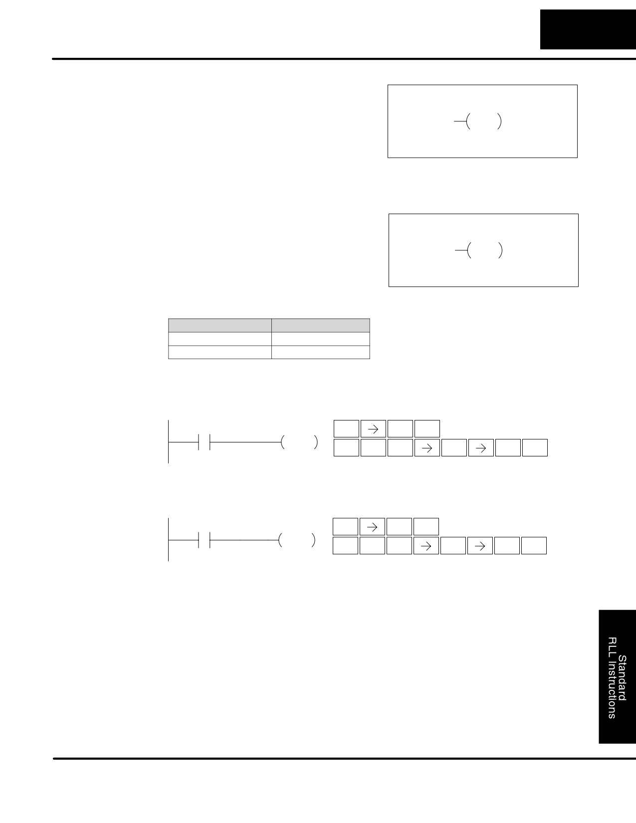
Or Out Immediate The Or Out Immediate instruction has
(OROUTI)
been designed to use more than 1 rung of
Y aaa
discrete logic to control a single output.
OROUTI
Multiple Or Out Immediate instructions
referencing the same output coil may be
used, since all contacts controlling the
output are ored together. If the status of
any rung is on at the time the instruction is
executed, the output will also be on.
Operand Data Type
DL130 Range
aaa
Outputs
Y
0-177
In the following example, when X1 is on, output point Y2 on the output module will
turn on. For instruction entry on the Handheld Programmer, you can use the
instruction number (#350) as shown, or type each letter of the command.
DirectSOFT32
Handheld Programmer Keystrokes
X1
Y2
$
B
ENT
STR
1
OUTI
O
D
F
A
ENT
ENT
INST#
3
5
0
C
ENT
2
In the following example, when X1 or X4 is on, Y2 will energize.
DirectSOFT32
Handheld Programmer Keystrokes
$
B
X1
Y2
ENT
STR
1
OR OUTI
O
D
F
A
ENT
ENT
INST#
3
5
0
C
Y2
ENT
X4
2
OR OUTI
$
E
ENT
STR
4
O
D
F
A
ENT
ENT
INST#
3
5
0
C
ENT
2
DL105 PLC User Manual, 2nd Edition, Rev. A
Standard RLL Instructions
5-25
Immediate Instructions
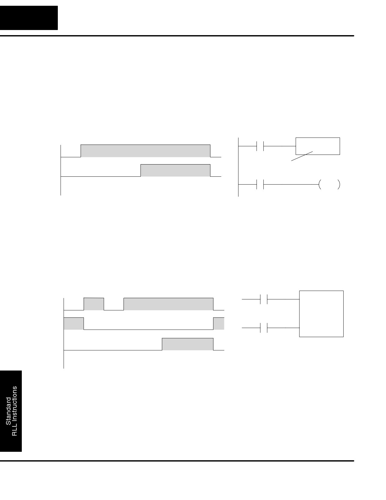
Set Immediate
The Set Immediate instruction
(SETI)
immediately sets, or turns on an output or
Y aaa
aaa
a range of outputs in the image register
SETI
and the corresponding output point(s) at
the time the instruction is executed. Once
the outputs are set it is not necessary for
the input to remain on. The Reset
Immediate instruction can be used to
reset the outputs.
Reset
The Reset Immediate instruction
Immediate
immediately resets, or turns off an output
Y aaa
aaa
(RSTI)
or a range of outputs in the image register
RSTI
and the output point(s) at the time the
instruction is executed. Once the outputs
are reset it is not necessary for the input to
remain on.
Operand Data Type
DL130 Range
aaa
Outputs
Y
0-177
In the following example, when X1 is on, Y2 through Y5 will be set on in the image
register and on the corresponding output points.
DirectSOFT32
Handheld Programmer Keystrokes
$
B
X1
Y2
Y5
ENT
STR
1
SETI
X
SHFT
I
C
F
ENT
SET
8
2
5
In the following example, when X1 is on, Y5 through Y22 will be reset (off) in the
image register and on the corresponding output module(s).
DirectSOFT32
Handheld Programmer Keystrokes
$
B
ENT
X1
Y2
Y5
STR
1
RSTI
S
I
C
F
SHFT
ENT
RST
8
2
5
DL105 PLC User Manual, 2nd Edition, Rev. A
Standard RLL Instructions
5-26
Timer, Counter, and Shift Register Instructions
Timer, Counter and Shift Register Instructions
Timers are used to time an event for a desired length of time. The single input timer
Using Timers
will time as long as the input is on. When the input changes from on to off the timer
current value is reset to 0. There is a tenth of a second and a hundredth of a second
timer available with a maximum time of 999.9 and 99.99 seconds respectively. There
is a discrete bit associated with each timer to indicate that the current value is equal
to or greater than the preset value. The timing diagram below shows the relationship
between the timer input, associated discrete bit, current value, and timer preset.
Seconds
0
1
2
3
4
5
6
7
8
X1
TMR
T1
X1
K30
Timer preset
T1
T1
Y0
OUT
Current
0
10
20
30
40
50
60
0
Value
1/10 Seconds
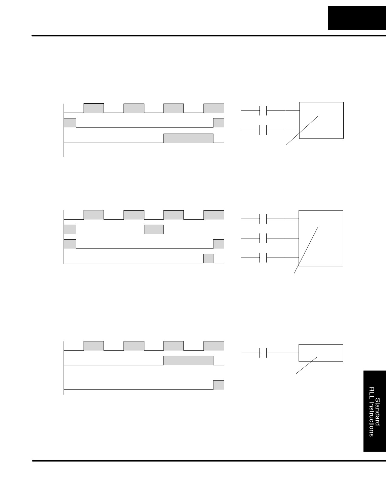
There are those applications that need an accumulating timer, meaning it has the
ability to time, stop, and then resume from where it previously stopped. The
accumulating timer works similarly to the regular timer, but two inputs are required.
The start/stop input starts and stops the timer. When the timer stops, the elapsed
time is maintained. When the timer starts again, the timing continues from the
elapsed time. When the reset input is turned on, the elapsed time is cleared and the
timer will start at 0 when it is restarted. There is a tenth of a second and a hundredth
of a second timer available with a maximum time of 9999999.9 and 999999.99
seconds respectively. The timing diagram below shows the relationship between the
timer input, timer reset, associated discrete bit, current value, and timer preset.
Seconds
X1
0
1
2
3
4
5
6
7
8
TMRA
T0
K30
X1
Start/Stop
X2
X2
Reset Input
T0
Current
0
10
10
20
30
40
50
0
Value
1/10 Seconds
DL105 PLC User Manual, 2nd Edition, Rev. A
Standard RLL Instructions
5-27
Timer, Counter, and Shift Register Instructions
Timer (TMR) and
The Timer instruction is a 0.1 second single
Timer Fast (TMRF)
input timer that times to a maximum of
999.9 seconds. The Timer Fast instruction
TMR
T aaa
is a 0.01 second single input timer that
B bbb
times up to a maximum of 99.99 seconds.
These timers will be enabled if the input
logic is true (on) and will be reset to 0 if the
Preset
Timer #
input logic is false (off).
Instruction Specifications
Timer Reference (Taaa): Specifies the
TMRF
T aaa
timer number.
B bbb
Preset Value (Bbbb): Constant value (K)
or a V memory location.
Current Value: Timer current values are
Preset
Timer #
accessed by referencing the associated V
or T memory location*. For example, the
timer current value for T3 physically
resides in V-memory location V3.
Discrete Status Bit: The discrete status
bit is referenced by the associated T
memory location. Operating as a “timer
done bit”, it will be on if the current value is
The timer discrete status bit and the
equal to or greater than the preset value.
current value are not specified in the timer
For example, the discrete status bit for
instruction.
Timer 2 is TA2.
NOTE: Timer preset constants (K) may
be changed by using a handheld
programmer, even when the CPU is in Run Mode. Therefore, a V-memory preset is
required only if the ladder program must change the preset.
Operand Data Type
DL130 Range
A/B
aaa
bbb
Timers
T
0-77
--
V memory for preset
2000-2377
V
--
values
4000-4177
Constants
K
--
0-9999
(preset only)
Timer discrete status
T/V
0-77 or V41100-41103
bits
Timer current values
V /T*
0-77
NOTE: * With the HPP, both the Timer discrete status bits and current value are
accessed with the same data reference. DirectSOFT32 uses separate references,
such as “T2” for discrete status bit for Timer T2, and “TA2” for the current value of
Timer T2.
You can perform functions when the timer reaches the specified preset using the
discrete status bit. Or, use comparative contacts to perform functions at different
time intervals, based on one timer. The examples on the following page show these
two methods of programming timers.
DL105 PLC User Manual, 2nd Edition, Rev. A
Standard RLL Instructions
5-28
Timer, Counter, and Shift Register Instructions
Timer Example
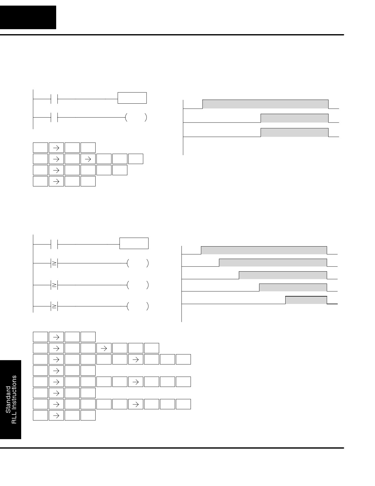
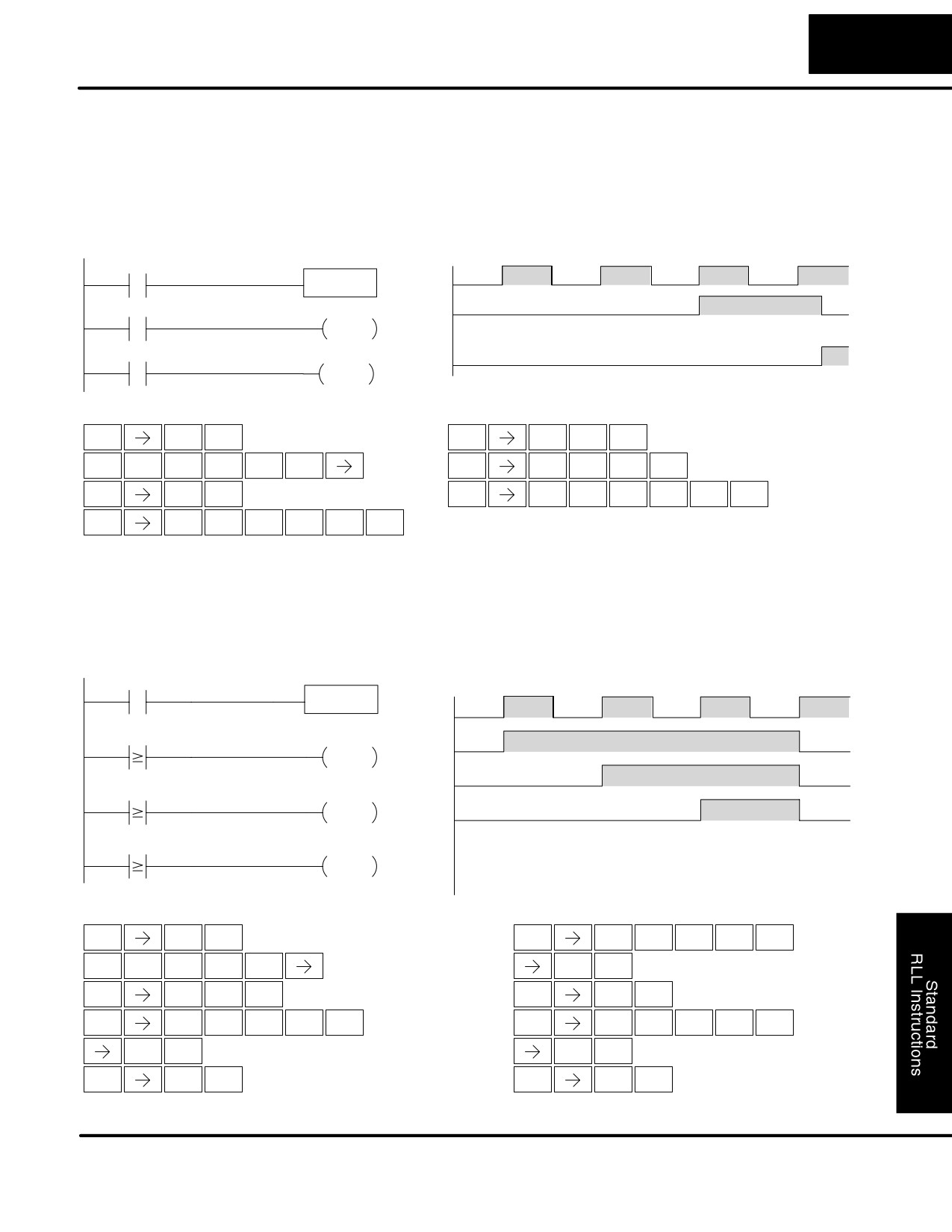
In the following example, a single input timer is used with a preset of 3 seconds. The
Using Discrete
timer discrete status bit (T2) will turn on when the timer has timed for 3 seconds. The
Status Bits
timer is reset when X1 turns off, turning the discrete status bit off and resetting the
timer current value to 0.
DirectSOFT
Timing Diagram
X1
Seconds
TMR
T2
0
1
2
3
4
5
6
7
8
K30
X1
T2
Y0
OUT
T2
Y0
Handheld Programmer Keystrokes
Current
$
B
0
10
20
30
40
50
60
0
ENT
Value
STR
1
1/10 Seconds
N
C
D
A
ENT
TMR
2
3
0
$
T
C
SHFT
ENT
STR
MLR
2
GX
A
ENT
OUT
0
Timer Example
In the following example, a single input timer is used with a preset of 4.5 seconds.
Using Comparative
Comparative contacts are used to energize Y3, Y4, and Y5 at one second intervals
Contacts
respectively. When X1 is turned off the timer will be reset to 0 and the comparative
contacts will turn off Y3, Y4, and Y5.
DirectSOFT
Timing Diagram
X1
Seconds
TMR
T20
0
1
2
3
4
5
6
7
8
K45
X1
TA20
K10
Y3
OUT
Y3
TA20
K20
Y4
Y4
OUT
Y5
TA20
K30
Y5
T2
OUT
Current
0
10
20
30
40
50
60
0
Value
1/10 Seconds
Handheld Programmer Keystrokes
$
B
ENT
STR
1
N
C
A
E
F
ENT
TMR
2
0
4
5
$
T
C
A
B
A
SHFT
ENT
STR
MLR
2
0
1
0
GX
D
ENT
OUT
3
$
T
C
A
C
A
SHFT
ENT
STR
MLR
2
0
2
0
GX
E
ENT
OUT
4
$
T
C
A
D
A
SHFT
ENT
STR
MLR
2
0
3
0
GX
F
ENT
OUT
5
DL105 PLC User Manual, 2nd Edition, Rev. A
Standard RLL Instructions
5-29
Timer, Counter, and Shift Register Instructions
Accumulating
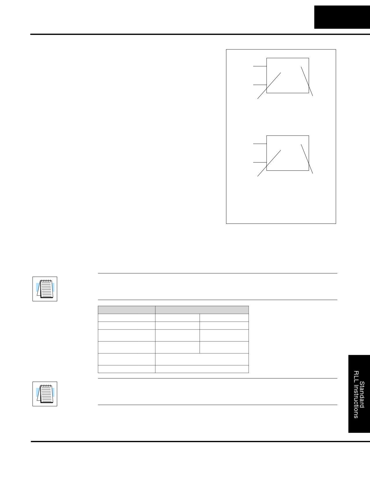
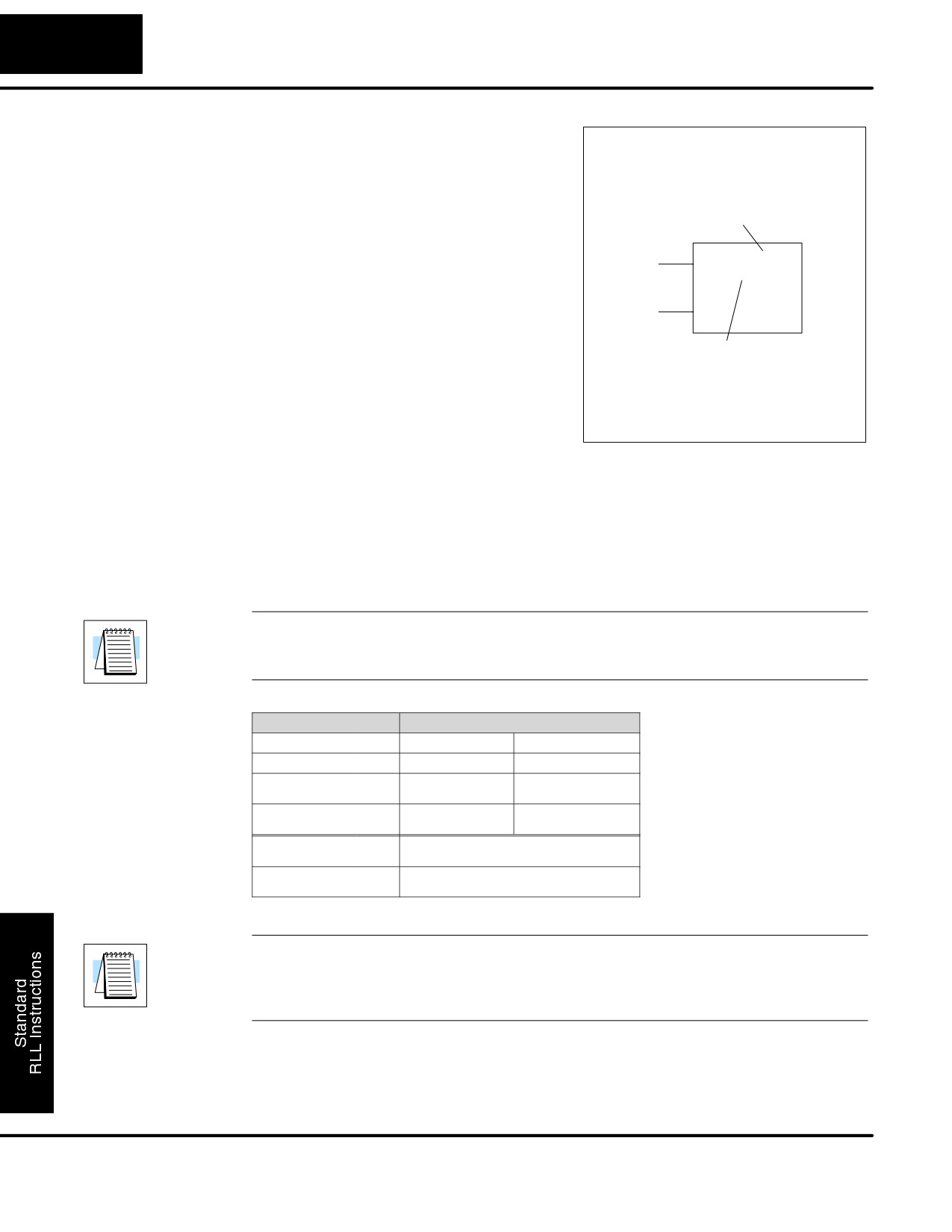
The Accumulating Timer is a 0.1 second
Timer (TMRA)
two input timer that will time to a maximum
Enable
TMRA
T aaa
of
9999999.9. The Accumulating Fast
B bbb
Timer is a 0.01 second two-input timer that
Accumulating Fast
Reset
Timer (TMRAF)
will time to a maximum of 999999.99.
Each one uses two timer registers in
V-memory. These timers have two inputs,
Preset
Timer #
an enable and a reset. The timer starts
timing when the enable is on and stops
when the enable is off (without resetting
the count). The reset will reset the timer
when on and allow the timer to time when
off.
Enable
TMRAF
T aaa
Instruction Specifications
B bbb
Timer Reference (Taaa): Specifies the
Reset
timer number.
Preset Value (Bbbb): Constant value (K)
or a V memory location.
Preset
Timer #
Current Value: Timer current values are
accessed by referencing the associated V
or T memory location*. For example, the
timer current value for T3 resides in
V-memory location V3.
Discrete Status Bit: The discrete status
bit is accessed by referencing the
The timer discrete status bit and the
associated T memory location. Operating
current value are not specified in the
as a “timer done bit”, it will be on if the
timer instruction.
current value is equal to or greater than
the preset value. For example the discrete
status bit for timer 2 would be T2.
NOTE: The accumulating type timer uses two consecutive V-memory locations
for the 8-digit value, and therefore two consecutive timer locations. For example, if
TMR 1 is used, the next available timer number is TMR 3.
Operand Data Type
DL130 Range
A/B
aaa
bbb
Timers
T
0-77
--
V memory for preset
2000-2376
V
--
values
4000-4176
Constants
K
--
0-99999999
(preset only)
Timer discrete status
T/V
0-77 or V41100-41103
bits
Timer current values
V /T*
0-77
NOTE: * With the HPP, both the Timer discrete status bits and current value are
accessed with the same data reference. DirectSOFT32 uses separate references, such
as T2 for discrete status bit for Timer T2, and TA2 for the current value of Timer T2.
The following examples show two methods of programming timers. One performs
functions when the timer reaches the preset value using the discrete status bit, or
use comparative contacts to perform functions at different time intervals.
DL105 PLC User Manual, 2nd Edition, Rev. A
Standard RLL Instructions
5-30
Timer, Counter, and Shift Register Instructions
Accumulating
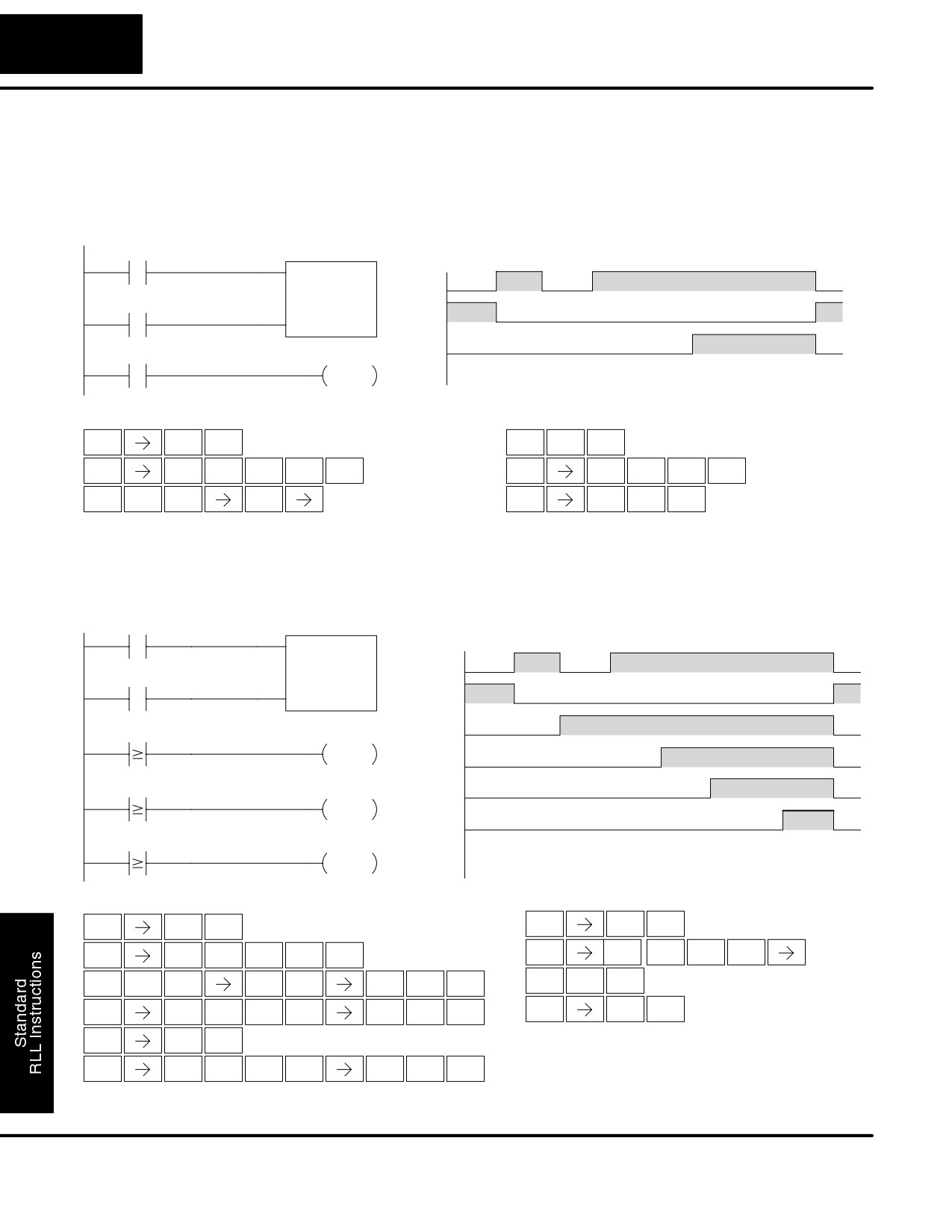
In the following example, a two input timer (accumulating timer) is used with a preset
Timer Example
of 3 seconds. The timer discrete status bit (T6) will turn on when the timer has timed
using Discrete
for 3 seconds. Notice in this example that the timer times for 1 second , stops for one
Status Bits
second, then resumes timing. The timer will reset when C10 turns on, turning the
discrete status bit off and resetting the timer current value to 0.
DirectSOFT
Timing Diagram
Seconds
X1
0
1
2
3
4
5
6
7
8
TMRA
T6
X1
K30
C10
C10
T6
Y7
T6
Current
0
10
10
20
30
40
50
0
OUT
Value
1/10 Seconds
Handheld Programmer Keystrokes
Handheld Programmer Keystrokes (cont)
$
B
D
A
ENT
ENT
STR
1
3
0
$
C
B
A
$
T
G
SHFT
ENT
SHFT
ENT
STR
2
1
0
STR
MLR
6
N
A
G
GX
B
A
SHFT
ENT
TMR
0
6
OUT
1
0
Accumulator Timer
In the following example, a single input timer is used with a preset of 4.5 seconds.
Example Using
Comparative contacts are used to energized Y3, Y4, and Y5 at one second intervals
Comparative
respectively. The comparative contacts will turn off when the timer is reset.
Contacts
DirectSOFT
Timing Diagram
X1
Seconds
TMRA
T20
0
1
2
3
4
5
6
7
8
K45
X1
C10
C10
TA20
K10
Y3
Y3
OUT
Y4
TA20
K20
Y4
Y5
OUT
T20
TA20
K30
Y5
Current
0
10
10
20
30
40
50
0
OUT
Value
1/10 Seconds
Handheld Programmer Keystrokes
Handheld Programmer Keystrokes (cont)
$
B
GX
E
ENT
ENT
OUT
4
STR
1
$
C
B
A
$
SHFT
T
C
A
STR
SHFT
2
1
0
ENT
STR
MLR
2
0
N
A
C
A
E
F
D
A
ENT
SHFT
ENT
3
0
TMR
0
2
0
4
5
$
T
C
A
B
A
GX
F
ENT
SHFT
ENT
OUT
5
STR
MLR
2
0
1
0
GX
D
ENT
OUT
3
$
T
C
A
C
A
SHFT
ENT
STR
MLR
2
0
2
0
DL105 PLC User Manual, 2nd Edition, Rev. A
Standard RLL Instructions
5-31
Timer, Counter, and Shift Register Instructions
Counters are used to count events . The counters available are up counters,
Using Counters
up/down counters, and stage counters (used with RLLPLUS programming).
The up counter has two inputs, a count input and a reset input. The maximum count
value is 9999. The timing diagram below shows the relationship between the counter
input, counter reset, associated discrete bit, current value, and counter preset.
X1
CNT
CT1
X1
Up
K3
X2
X2
Reset
CT1
Current
1
2
3
4
0
Counter preset
Value
Counts
The up down counter has three inputs, a count up input, count down input and reset
input. The maximum count value is 99999999. The timing diagram below shows the
relationship between the counter input, counter reset, associated discrete bit,
current value, and counter preset.
X1
UDC
CT2
X1
K3
Up
X2
X2
Down
X3
X3
CT2
Reset
Current
1
2
1
2
3
0
Value
Counts
Counter preset
The stage counter has a count input and is reset by the RST instruction. This
instruction is useful when programming using the RLLPLUS structured programming.
The maximum count value is 9999. The timing diagram below shows the relationship
between the counter input, associated discrete bit, current value, counter preset and
reset instruction.
X1
X1
SGCNT
CT2
K3
Up
CT2
Current
1
2
3
4
0
Value
Counts
Counter preset
RST
CT2
DL105 PLC User Manual, 2nd Edition, Rev. A
Standard RLL Instructions
5-32
Timer, Counter, and Shift Register Instructions
Counter
The Counter is a two input counter that
(CNT)
increments when the count input logic
transitions from off to on. When the counter
reset input is on the counter resets to 0.
When the current value equals the preset
Counter #
value, the counter status bit comes on and
the counter continues to count up to a
Count
CNT
CT aaa
maximum count of 9999. The maximum
B bbb
value will be held until the counter is reset.
Reset
Instruction Specifications
Counter Reference (CTaaa): Specifies
the counter number.
Preset
Preset Value (Bbbb): Constant value (K)
or a V memory location.
Current Values: Counter current values
are accessed by referencing the
associated V or CT memory locations*.
The counter discrete status bit and the
The V-memory location is the counter
current value are not specified in the
location + 1000. For example, the counter
counter instruction.
current value for CT3 resides in V memory
location V1003.
Discrete Status Bit: The discrete status bit is accessed by referencing the
associated CT memory location. It will be on if the value is equal to or greater than the
preset value. For example the discrete status bit for counter 2 would be CT2.
NOTE: Counter preset constants (K) may be changed by using a programming
device, even when the CPU is in Run Mode. Therefore, a V-memory preset is
required only if the ladder program must change the preset.
Operand Data Type
DL130 Range
A/B
aaa
bbb
Counters
CT
0-77
--
V memory
2000-2377
V
--
(preset only)
4000-4177
Constants
K
--
0-9999
(preset only)
Counter discrete
CT/V
0-77 or V41140-41143
status bits
Counter current
V/CT*
1000-1077
values
NOTE: * With the HPP, both the Counter discrete status bits and current value are
accessed with the same data reference. DirectSOFT32 uses separate references,
such as “CT2” for discrete status bit for Counter CT2, and “CTA2” for the current
value of Counter CT2.
DL105 PLC User Manual, 2nd Edition, Rev. A
Standard RLL Instructions
5-33
Timer, Counter, and Shift Register Instructions
Counter Example
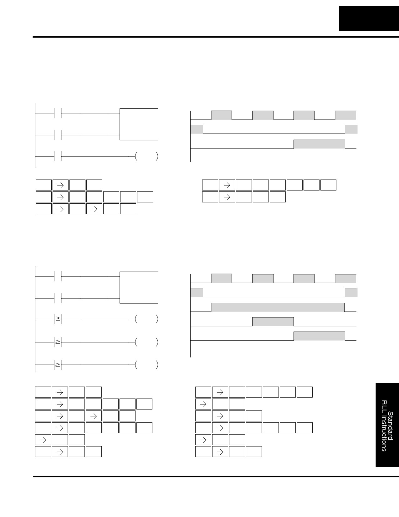
In the following example, when X1 makes an off to on transition, counter CT2 will
Using Discrete
increment by one. When the current value reaches the preset value of 3, the counter
Status Bits
status bit CT2 will turn on and energize Y7. When the reset C10 turns on, the counter
status bit will turn off and the current value will be 0. The current value for counter
CT2 will be held in V memory location V1002.
DirectSOFT
Counting diagram
X1
CNT
CT2
X1
K3
C10
C10
CT2
Y7
Y7
OUT
Current
1
2
3
4
0
Value
Handheld Programmer Keystrokes
Handheld Programmer Keystrokes (cont)
$
B
$
C
T
C
ENT
SHFT
SHFT
ENT
STR
1
STR
2
MLR
2
$
C
B
A
GX
B
A
SHFT
ENT
ENT
STR
2
1
0
OUT
1
0
GY
C
D
ENT
CNT
2
3
Counter Example
In the following example, when X1 makes an off to on transition, counter CT2 will
Using Comparative
increment by one. Comparative contacts are used to energize Y3, Y4, and Y5 at
Contacts
different counts. When the reset C10 turns on, the counter status bit will turn off and
the counter current value will be 0, and the comparative contacts will turn off.
DirectSOFT
Counting diagram
X1
CNT
CT2
X1
K3
C10
C10
CTA2
K1
Y3
Y3
OUT
Y4
CTA2
K2
Y4
Y5
OUT
Current
1
2
3
4
0
Value
CTA2
K3
Y5
OUT
Handheld Programmer Keystrokes
Handheld Programmer Keystrokes (cont)
$
B
$
C
T
C
ENT
SHFT
SHFT
STR
1
STR
2
MLR
2
$
SHFT
C
B
A
ENT
C
ENT
STR
2
1
0
2
GY
C
D
GX
E
ENT
ENT
CNT
2
3
OUT
4
$
C
T
C
$
C
T
C
SHFT
SHFT
SHFT
SHFT
STR
2
MLR
2
STR
2
MLR
2
B
D
ENT
ENT
1
3
GX
D
GX
F
ENT
ENT
OUT
3
OUT
5
DL105 PLC User Manual, 2nd Edition, Rev. A
Standard RLL Instructions
5-34
Timer, Counter, and Shift Register Instructions
Stage Counter
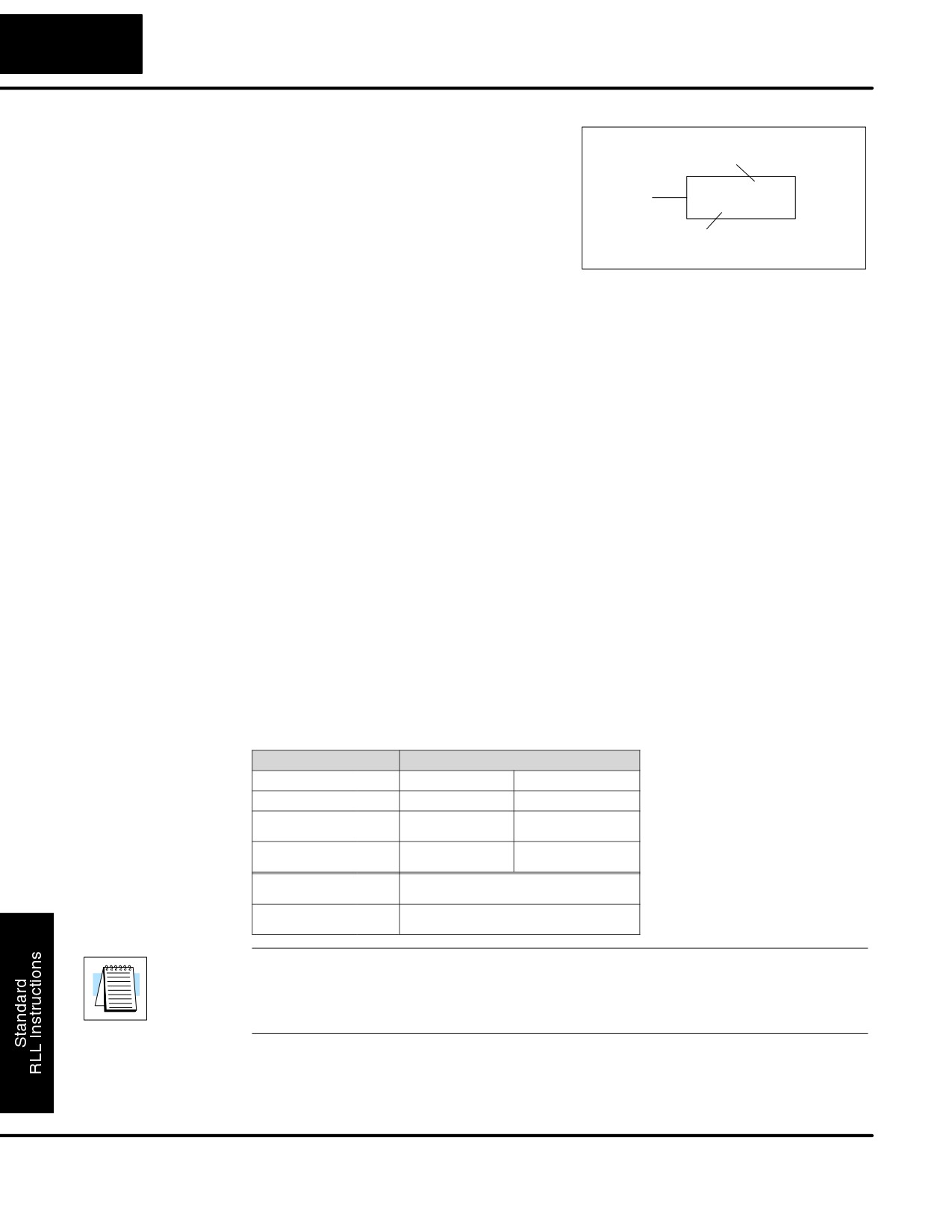
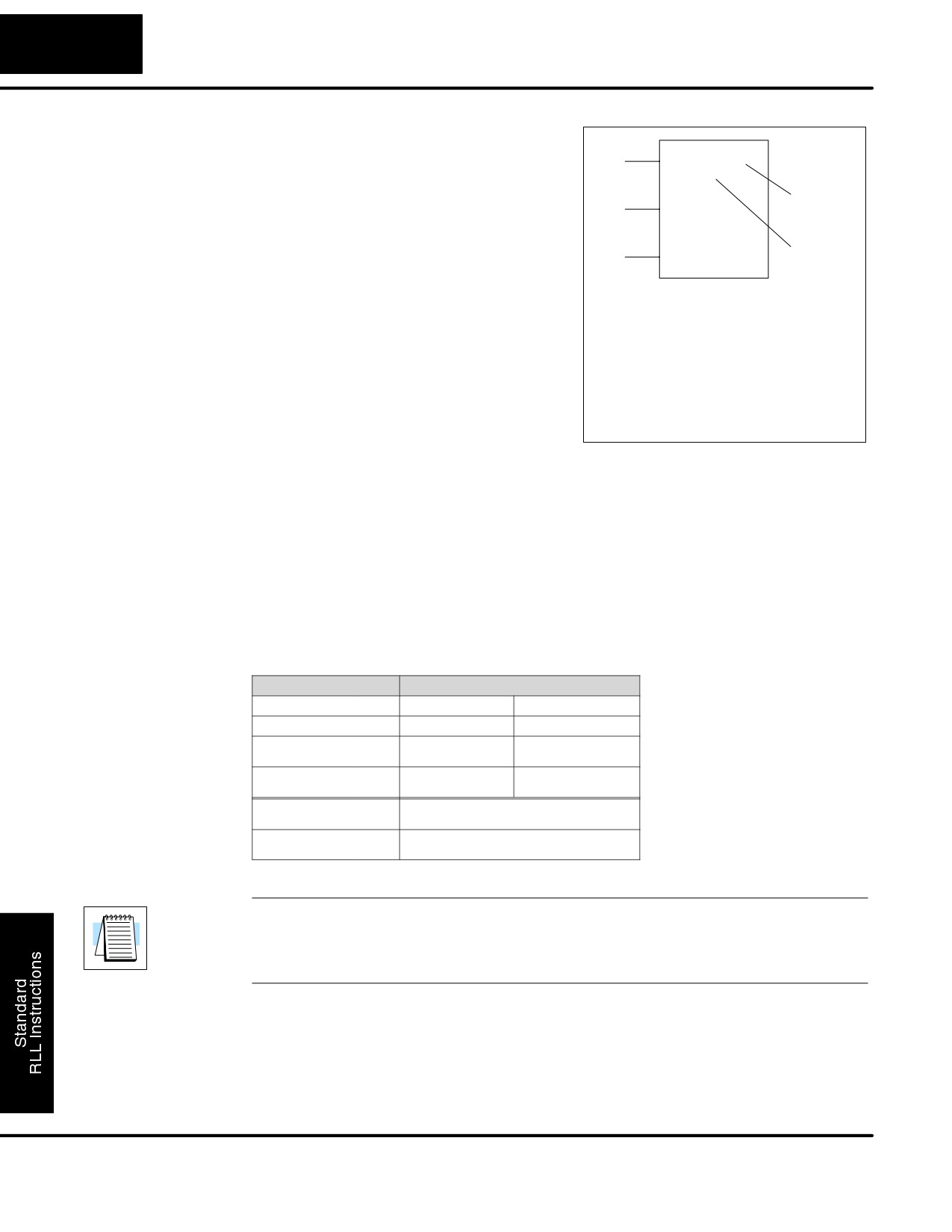
The Stage Counter is a single input counter
(SGCNT)
that increments when the input logic
Counter #
transitions from off to on. This counter
differs from other counters since it will hold
SGCNT
CT aaa
B bbb
its current value until reset using the RST
instruction. The Stage Counter is designed
Preset
for use in RLLPLUS programs but can be
used in relay ladder logic programs. When
the current value equals the preset value,
The counter discrete status bit and the
the counter status bit turns on and the
current value are not specified in the
counter instruction.
counter continues to count up to a
maximum count of 9999. The maximum
value will be held until the counter is reset.
Instruction Specifications
Counter Reference (CTaaa): Specifies
the counter number.
Preset Value (Bbbb): Constant value (K)
or a V memory location.
Current Values: Counter current values
are accessed by referencing the
associated V or CT memory locations*.
The V-memory location is the counter
location + 1000. For example, the counter
current value for CT3 resides in V memory
location V1003.
Discrete Status Bit: The discrete status
bit is accessed by referencing the
associated CT memory location. It will be
on if the value is equal to or greater than the
preset value. For example the discrete
status bit for counter 2 would be CT2.
Operand Data Type
DL130 Range
A/B
aaa
bbb
Counters
CT
0-77
--
V memory
V
--
2000-2377
(preset only)
Constants
K
--
0-9999
(preset only)
Counter discrete
CT/V
0-77 or V41140-41143
status bits
Counter current
V/CT*
1000-1077
values
NOTE: * With the HPP, both the Counter discrete status bits and current value are
accessed with the same data reference. DirectSOFT32 uses separate references,
such as “CT2” for discrete status bit for Counter CT2, and “CTA2” for the current
value of Counter CT2.
DL105 PLC User Manual, 2nd Edition, Rev. A
Standard RLL Instructions
5-35
Timer, Counter, and Shift Register Instructions
Stage Counter
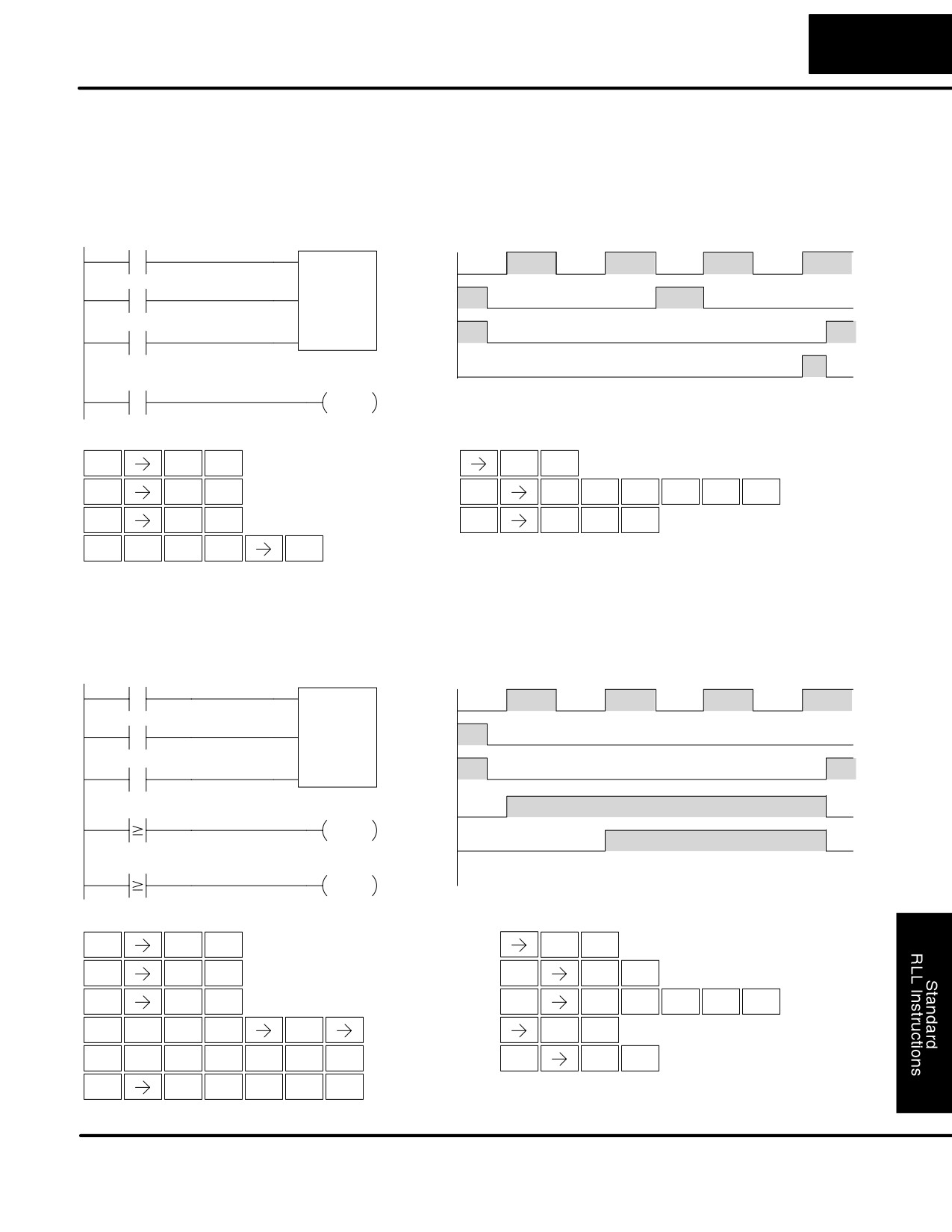
In the following example, when X1 makes an off to on transition, stage counter CT7
Example Using
will increment by one. When the current value reaches 3, the counter status bit CT7
Discrete Status
will turn on and energize Y7. The counter status bit CT7 will remain on until the
Bits
counter is reset using the RST instruction. When the counter is reset, the counter
status bit will turn off and the counter current value will be 0. The current value for
counter CT7 will be held in V memory location V1007.
DirectSOFT
Counting diagram
X1
SGCNT CT7
X1
K3
CT7
Y7
Y10
OUT
Current
1
2
3
4
0
Value
C5
CT7
RST
RST
CT7
Handheld Programmer Keystrokes
Handheld Programmer Keystrokes (cont)
$
B
GX
B
A
ENT
ENT
STR
1
OUT
1
0
S
G
GY
$
C
F
SHFT
SHFT
SHFT
SHFT
ENT
RST
6
CNT
STR
2
5
H
D
S
C
T
H
ENT
SHFT
SHFT
ENT
7
3
RST
2
MLR
7
$
C
T
H
SHFT
SHFT
ENT
STR
2
MLR
7
Stage Counter
In the following example, when X1 makes an off to on transition, counter CT2 will
Example Using
increment by one. Comparative contacts are used to energize Y3, Y4, and Y5 at
Comparative
different counts. Although this is not shown in the example, when the counter is reset
Contacts
using the Reset instruction, the counter status bit will turn off and the current value
will be 0. The current value for counter CT2 will be held in V memory location V1002.
DirectSOFT
Counting diagram
X1
SGCNT CT2
K10
X1
CT2
K1
Y3
Y3
OUT
Y4
CT2
K2
Y4
OUT
Y5
Current
1
2
3
4
0
CT2
K3
Y5
Value
OUT
Handheld Programmer Keystrokes
Handheld Programmer Keystrokes (cont)
$
B
$
C
T
C
ENT
SHFT
SHFT
STR
1
STR
2
MLR
2
SHFT
S
G
SHFT
GY
C
ENT
RST
6
CNT
2
C
B
A
GX
E
ENT
ENT
2
1
0
OUT
4
$
C
T
C
$
C
T
C
SHFT
SHFT
SHFT
SHFT
STR
2
MLR
2
STR
2
MLR
2
B
D
ENT
ENT
1
3
GX
D
ENT
GX
F
ENT
OUT
3
OUT
5
DL105 PLC User Manual, 2nd Edition, Rev. A
Standard RLL Instructions
5-36
Timer, Counter, and Shift Register Instructions
Up Down Counter
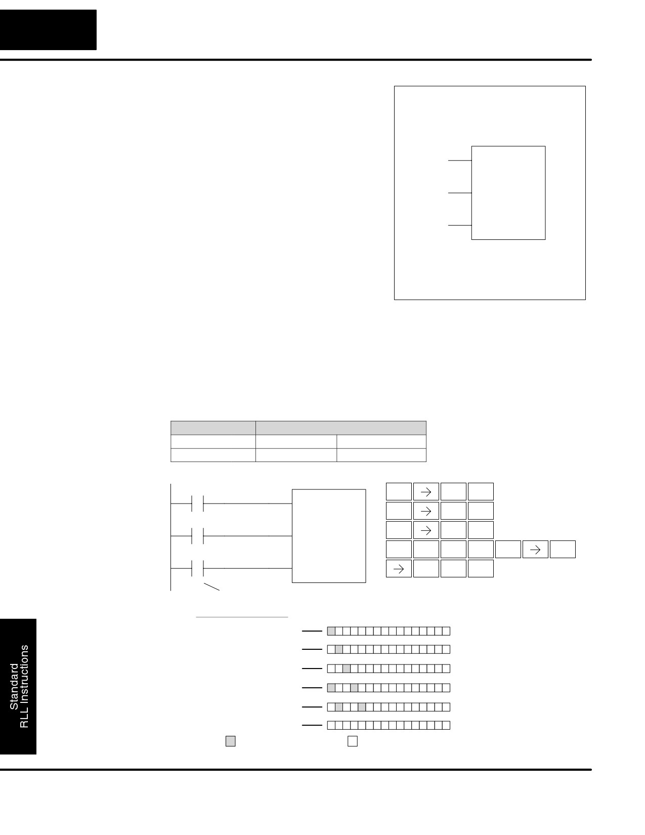
This Up/Down Counter counts up on each
(UDC)
off to on transition of the Up input and
Up
UDC
CT aaa
B bbb
counts down on each off to on transition of
the Down input. The counter is reset to 0
Down
Counter #
when the Reset input is on. The count
range is 0-99999999. The count input not
being used must be off in order for the
Reset
Preset
active count input to function.
Instruction Specification
Caution: The UDC uses two
Counter Reference (CTaaa): Specifies
V memory locations for the 8 digit
the counter number.
current value. This means that the
Preset Value (Bbbb): Constant value (K)
UDC uses two consecutive
or two consecutive V memory locations.
counter locations. If UDC CT1 is
Current Values: Current count is a double
used in the program, the next
word value accessed by referencing the
available counter is CT3.
associated V or CT memory locations*.
The V-memory location is the counter
The counter discrete status bit and the
location + 1000. For example, the counter
current value are not specified in the
counter instruction.
current value for CT5 resides in V memory
location V1005 and V1006.
Discrete Status Bit: The discrete status
bit is accessed by referencing the
associated CT memory location.
Operating as a “counter done bit” it will be
on if the value is equal to or greater than the
preset value. For example the discrete
status bit for counter 2 would be CT2.
Operand Data Type
DL130 Range
A/B
aaa
bbb
Counters
CT
0-77
--
V memory
2000-2377
V
--
(preset only)
4000-4177
Constants
K
--
0-99999999
(preset only)
Counter discrete
CT/V
0-77 or V41140-41143
status bits
Counter current
V/CT*
1000-1077
values
NOTE: * With the HPP, both the Counter discrete status bits and current value are
accessed with the same data reference. DirectSOFT32 uses separate references,
such as “CT2” for discrete status bit for Counter CT2, and “CTA2” for the current
value of Counter CT2.
DL105 PLC User Manual, 2nd Edition, Rev. A
Standard RLL Instructions
5-37
Timer, Counter, and Shift Register Instructions
Up / Down Counter
In the following example if X2 and X3 are off ,when X1 toggles from off to on the
Example Using
counter will increment by one. If X1 and X3 are off the counter will decrement by one
Discrete Status
when X2 toggles from off to on. When the count value reaches the preset value of 3,
Bits
the counter status bit will turn on. When the reset X3 turns on, the counter status bit
will turn off and the current value will be 0.
DirectSOFT32
Counting Diagram
X1
UDC
CT2
K3
X1
X2
X2
X3
X3
CT2
CT2
Y7
Current
1
2
1
2
3
0
OUT
Value
Handheld Programmer Keystrokes
Handheld Programmer Keystrokes (cont)
$
B
D
ENT
ENT
STR
1
3
$
C
$
C
T
C
ENT
SHFT
SHFT
ENT
STR
2
STR
2
MLR
2
$
D
GX
B
A
ENT
ENT
STR
3
OUT
1
0
U
D
C
C
SHFT
ISG
3
2
2
Up / Down Counter
In the following example, when X1 makes an off to on transition, counter CT2 will
Example Using
increment by one. Comparative contacts are used to energize Y3 and Y4 at different
Comparative
counts. When the reset (X3) turns on, the counter status bit will turn off, the current
Contacts
value will be 0, and the comparative contacts will turn off.
DirectSOFT32
Counting Diagram
X1
UDC
CT2
V2000
X1
X2
X2
X3
X3
CTA2
K1
Y3
Y3
OUT
Y4
CTA2
K2
Y4
Current
1
2
3
4
0
Value
OUT
Handheld Programmer Keystrokes
Handheld Programmer Keystrokes (cont)
$
B
B
ENT
ENT
STR
1
1
$
C
GX
D
ENT
ENT
STR
2
OUT
3
$
D
$
C
T
C
ENT
SHFT
SHFT
STR
3
STR
2
MLR
2
U
D
C
C
C
SHFT
ENT
ISG
3
2
2
2
V
C
A
A
A
GX
E
SHFT
ENT
ENT
AND
2
0
0
0
OUT
4
$
C
T
C
SHFT
SHFT
STR
2
MLR
2
DL105 PLC User Manual, 2nd Edition, Rev. A
Standard RLL Instructions
5-38
Timer, Counter, and Shift Register Instructions
Shift Register
The Shift Register instruction shifts data
(SR)
through a predefined number of control
relays. The control ranges in the shift
register block must start at the beginning
of an 8 bit boundary use 8-bit blocks.
DATA
SR
The Shift Register has three contacts.
S Data — determines the value (1 or
From A aaa
0) that will enter the register
CLOCK
S Clock — shifts the bits one position
To B
bbb
on each low to high transition
RESET
S Reset —resets the Shift Register to
all zeros.
With each off to on transition of the clock input, the bits which make up the shift
register block are shifted by one bit position and the status of the data input is placed
into the starting bit position in the shift register. The direction of the shift depends on
the entry in the From and To fields. From C0 to C17 would define a block of sixteen
bits to be shifted from left to right. From C17 to C0 would define a block of sixteen
bits, to be shifted from right to left. The maximum size of the shift register block
depends on the number of available control relays. The minimum block size is 8
control relays.
Operand Data Type
DL130 Range
A/B
aaa
bbb
Control Relay
C
0-377
0-377
DirectSOFT32
Handheld Programmer Keystrokes
$
B
X1
ENT
Data Input
SR
STR
1
$
C
ENT
STR
2
From
C0
X2
$
D
Clock Input
ENT
STR
3
S
R
A
To
C17
SHFT
SHFT
SHFT
RST
ORN
0
X3
Reset Input
B
H
ENT
1
7
Inputs on Successive Scans
Shift Register Bits
Data
Clock
Reset
C0
C17
1
0-1-0
0
0
0-1-0
0
0
0-1-0
0
1
0-1-0
0
0
0-1-0
0
0
0
1
- indicates on
- indicates off
DL105 PLC User Manual, 2nd Edition, Rev. A
Standard RLL Instructions
5-39
Accumulator / Stack Load and Output Data Instructions
Accumulator / Stack Load and Output Data Instructions
Using the
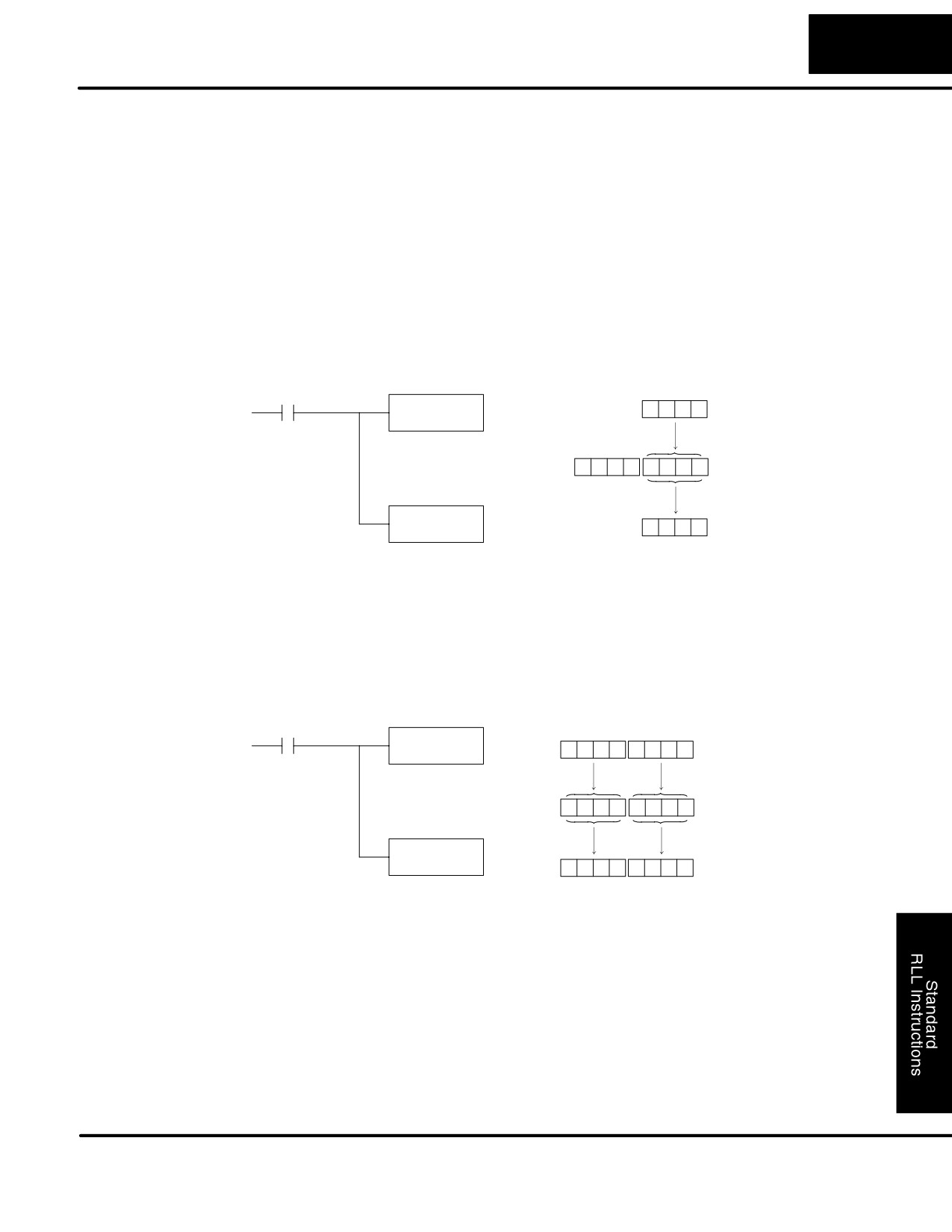
The accumulator in the DL105 internal CPUs is a 32 bit register which is used as a
Accumulator
temporary storage location for data that is being copied or manipulated in some
manor. For example, you have to use the accumulator to perform math operations
such as add, subtract, multiply, etc. Since there are 32 bits, you can use up to an
8-digit BCD number. The accumulator is reset to 0 at the end of every CPU scan.
Copying Data to
The Load and Out instructions and their variations are used to copy data from a
the Accumulator
V-memory location to the accumulator, or, to copy data from the accumulator to V
memory. The following example copies data from V-memory location V2000 to
V-memory location V2010.
V2000
X1
LD
8
9
3
5
V2000
Unused accumulator bits
Copy data from V2000 to the
are set to zero
lower 16 bits of the accumu-
lator
0
0
0
0
8
9
3
5
Acc.
OUT
V2010
8
9
3
5
Copy data from the lower 16 bits
V2010
of the accumulator to V2010
Since the accumulator is 32 bits and V memory locations are 16 bits the Load Double
and Out Double (or variations thereof) use two consecutive V-memory locations or 8
digit BCD constants to copy data either to the accumulator from a V-memory
address or from a V-memory address to the accumulator. For example if you wanted
to copy data from V2000 and V2001 to V2010 and V2011 the most efficient way to
perform this function would be as follows:
X1
V2001
V2000
LDD
V2000
6
7
3
9
5
0
2
6
Copy data from V2000 and
V2001 to the accumulator
6
7
3
9
5
0
2
6
Acc.
OUTD
V2010
6
7
3
9
5
0
2
6
Copy data from the accumulator to
V2011
V2010
V2010 and V2011
DL105 PLC User Manual, 2nd Edition, Rev. A
Standard RLL Instructions
5-40
Accumulator / Stack Load and Output Data Instructions
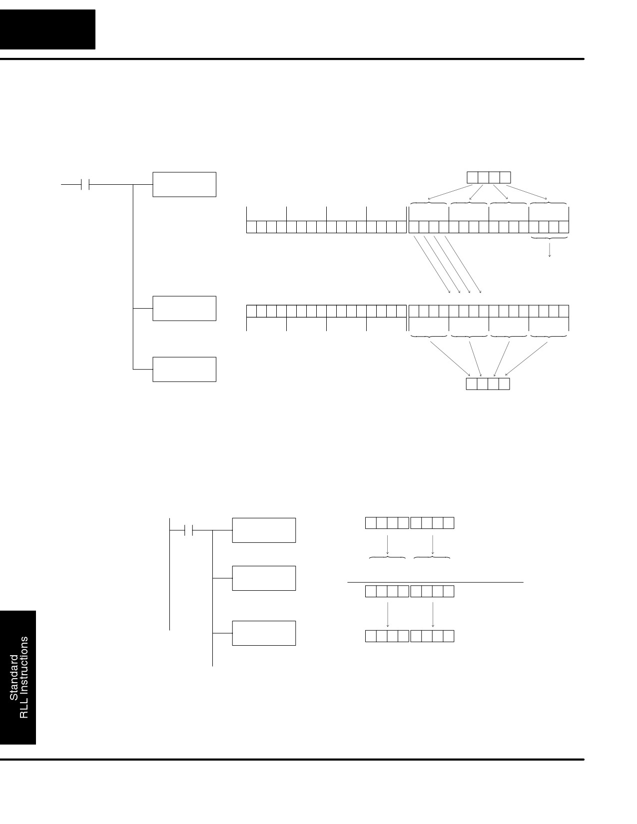
Instructions that manipulate data also use the accumulator. The result of the
Changing the
manipulated data resides in the accumulator. The data that was being manipulated
Accumulator Data
is cleared from the accumulator. The following example loads the constant value
4935 into the accumulator, shifts the data right 4 bits, and outputs the result to
V2010.
X1
Constant
4
9
3
5
LD
K4935
Load the value 4935 into the
accumulator
31 30 29 28
27 26 25 24
23 22 21 20
19 18 17 16
15 14 13 12
11 10
9
8
7
6
5
4
3
2
1
0
Acc.
0
0
0
0
0
0
0
0
0
0
0
0
0
0
0
0
0
1
0
0
1
0
0
1
0
0
1
1
0
1
0
1
The upper 16 bits of the accumulator
will be set to 0
S
S
S
S
Shifted out of
accumulator
SHFR
31 30 29 28 27 26 25 24 23 22 21 20 19 18 17 16
15 14 13 12 11 10
9
8
7
6
5
4
3
2
1
0
K4
Acc.
0
0
0
0
0
0
0
0
0
0
0
0
0
0
0
0
0
0
0
0
0
1
0
0
1
0
0
1
0
0
1
1
Shift the data in the accumulator
4 bits (K4) to the right
OUT
V2010
0
4
9
3
Output the lower 16 bits of the ac-
cumulator to V2010
V2010
Some of the data manipulation instructions use 32 bits. They use two consecutive V
memory locations or an 8 digit BCD constant to manipulate data in the accumulator.
In the following example, when X1 is on, the value in V2000 and V2001 will be loaded
into the accumulator using the Load Double instruction. The value in the
accumulator is added with the value in V2006 and V2007 using the Add Double
instruction. The value in the accumulator is copied to V2010 and V2011 using the
Out Double instruction.
V2001
V2000
X1
6
7
3
9
5
0
2
6
LDD
V2000
Load the value in V2000 and
V2001 into the accumulator
6
7
3
9
5
0
2
6
(Accumulator)
ADDD
+
2
0
0
0
4
0
4
6
(V2006 and V2007)
V2006
Acc.
8
7
3
9
9
0
7
2
Add the value in the
accumulator with the value
in V2006 and V2007
OUTD
V2010
8
7
3
9
9
0
7
2
Copy the value in the
V2011
V2010
accumulator to V2010 and
V2011
DL105 PLC User Manual, 2nd Edition, Rev. A
Standard RLL Instructions
5-41
Accumulator / Stack Load and Output Data Instructions
Using the
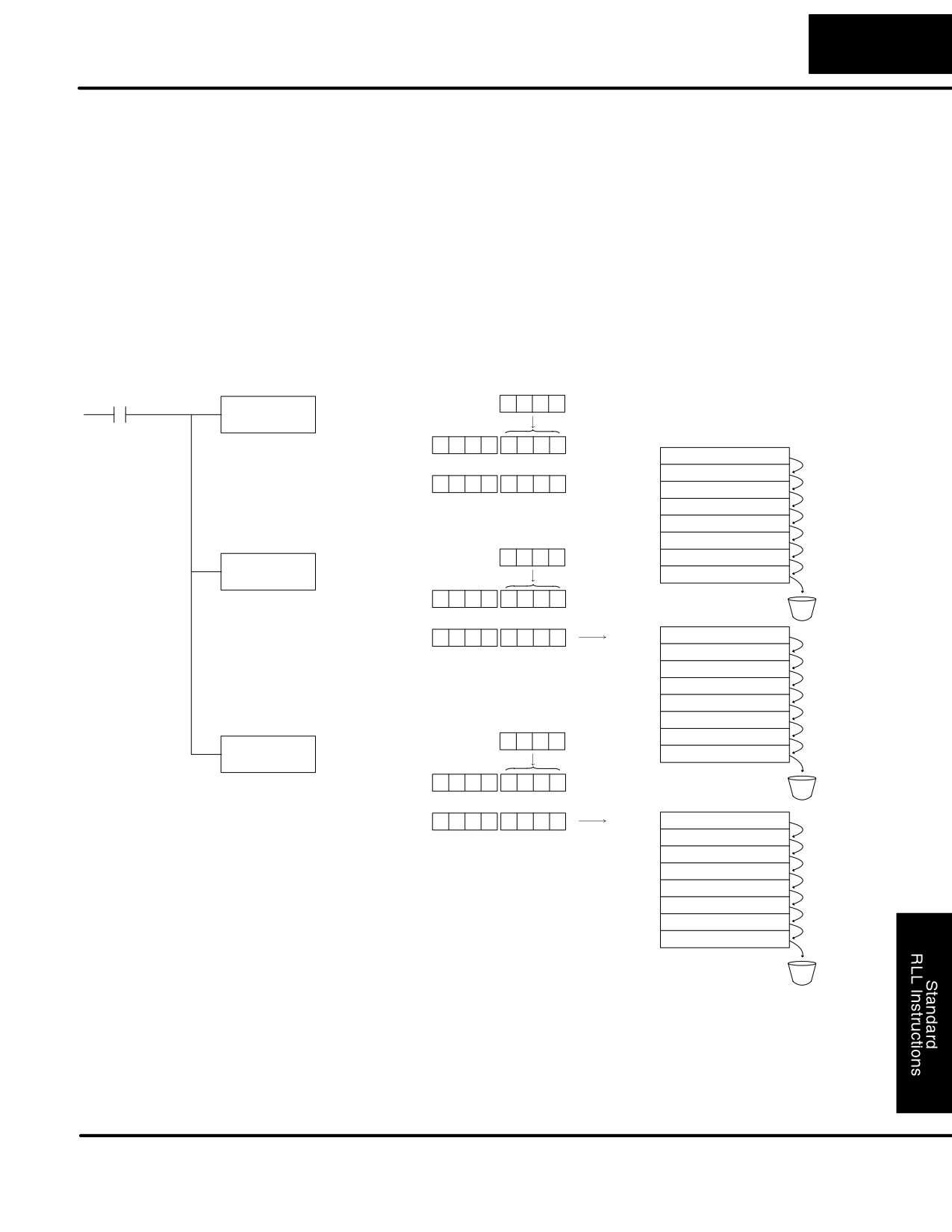
The accumulator stack is used for instructions that require more than one parameter
to execute a function or for user defined functionality. The accumulator stack is used
Accumulator Stack
when more than one Load instruction is executed without the use of an Out
instruction. The first load instruction in the scan places a value into the accumulator.
Every Load instruction thereafter without the use of an Out instruction places a value
into the accumulator and the value that was in the accumulator is placed onto the
accumulator stack. The Out instruction nullifies the previous load instruction and
does not place the value that was in the accumulator onto the accumulator stack
when the next load instruction is executed. Every time a value is placed onto the
accumulator stack the other values in the stack are pushed down one location. The
accumulator is eight levels deep (eight 32 bit registers). If there is a value in the
eighth location when a new value is placed onto the stack, the value in the eighth
location is pushed off the stack and cannot be recovered.
X1
Constant
3
2
4
5
LD
K3245
Current Acc. value
Accumulator Stack
Load the value 3245 into the accumu-
Acc.
0
0
0
0
3
2
4
5
lator
Level 1
X
X
X
X
X
X
X
X
Previous Acc. value
Level 2
X
X X X X X X
X
Acc.
X
X
X
X
X
X
X
X
Level 3
X
X X X X X X
X
Level 4
X
X X X X X X
X
Level 5
X
X X X X X X
X
Level 6
X
X X X X X X
X
Constant
5
1
5
1
Level 7
X
X
X
X
X
X
X
X
LD
Level 8
X
X
X
X
X
X
X
X
K5151
Current Acc. value
Acc.
0
0
0
0
5
1
5
1
Load the value 5151 into the accumu-
lator, pushing the value 3245 onto the
Bucket
Previous Acc. value
Accumulator Stack
stack
Acc.
0
0
0
0
3
2
4
5
Level 1
0
0
0
0
3
2
4
5
Level 2
X
X X X X X X
X
Level 3
X
X X X X X X
X
Level 4
X
X X X X X X
X
Level 5
X
X X X X X X
X
Level 6
X
X X X X X X
X
Level 7
X
X X X X X X
X
Constant
6
3
6
3
LD
Level 8
X
X X X X X X
X
K6363
Current Acc. value
Acc.
0
0
0
0
6
3
6
3
Load the value 6363 into the accumu-
Bucket
lator, pushing the value 5151 to the 1st
Previous Acc. value
Accumulator Stack
stack location and the value 3245 to
the 2nd stack location
Acc.
0
0
0
0
5
1
5
1
Level 1
0
0
0
0
5
1
5
1
Level 2
0
0
0
0
3
2
4
5
Level 3
X
X X X X X X
X
Level 4
X
X X X X X X
X
Level 5
X
X X X X X X
X
Level 6
X
X X X X X X
X
Level 7
X
X X X X X X
X
Level 8
X
X X X X X X
X
Bucket
The POP instruction rotates values upward through the stack into the accumulator.
When a POP is executed the value which was in the accumulator is cleared and the
value that was on top of the stack is in the accumulator. The values in the stack are
shifted up one position in the stack.
DL105 PLC User Manual, 2nd Edition, Rev. A
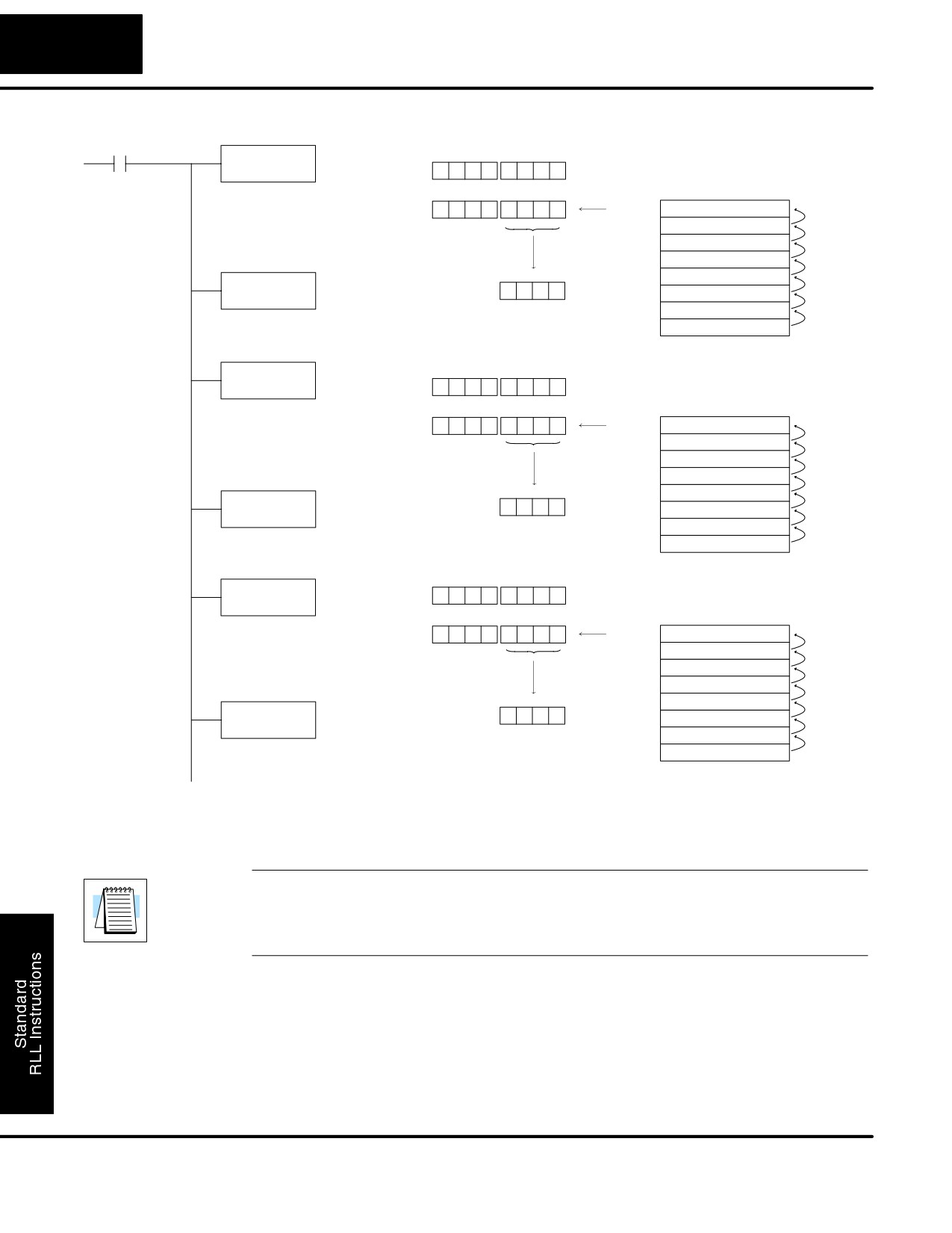
Standard RLL Instructions
5-42
Accumulator / Stack Load and Output Data Instructions
X1
Previous Acc. value
POP
Acc.
X
X
X
X
X
X
X
X
Current Acc. value
Accumulator Stack
POP the 1st value on the stack into the
accumulator and move stack values
Acc.
0
0
0
0
4
5
4
5
Level 1
0
0
0
0
3
7
9
2
up one location
Level 2
0
0
0
0
7
9
3
0
Level 3
X
X X X X X X
X
Level 4
X
X X X X X X
X
Level 5
X
X X X X X X
X
OUT
V2000
4
5
4
5
Level 6
X
X X X X X X
X
V2000
Level 7
X
X X X X X X
X
Copy data from the accumulator to
Level 8
X
X X X X X X
X
V2000
Previous Acc. value
POP
Acc.
0
0
0
0
4
5
4
5
Current Acc. value
Accumulator Stack
POP the 1st value on the stack into the
accumulator and move stack values
Acc.
0
0
0
0
3
7
9
2
Level 1
0
0
0
0
7
9
3
0
up one location
Level 2
X
X X X X X X
X
Level 3
X
X X X X X X
X
Level 4
X
X X X X X X
X
Level 5
X
X X X X X X
X
OUT
V2001
3
7
9
2
Level 6
X
X X X X X X
X
V2001
Level 7
X
X X X X X X
X
Copy data from the accumulator to
Level 8
X
X X X X X X
X
V2001.
Previous Acc. value
POP
Acc.
0
0
0
0
3
7
9
2
Current Acc. value
Accumulator Stack
POP the 1st value on the stack into the
Acc.
X
X
X
X
7
9
3
0
Level 1
X
X X X X X X
X
accumulator and move stack values
up one location
Level 2
X
X X X X X X
X
Level 3
X
X X X X X X
X
Level 4
X
X X X X X X
X
Level 5
X
X X X X X X
X
OUT
V2002
7
9
3
0
Level 6
X
X X X X X X
X
V2002
Level 7
X
X X X X X X
X
Copy data from the accumulator to
Level 8
X
X X X X X X
X
V2002
Using Pointers
Many of the DL105 series instructions will allow V-memory pointers as a operand
(commonly known as indirect addressing). Pointers allow instructions to obtain data
from V-memory locations referenced by the pointer value.
NOTE: DL105 V-memory addressing is in octal. However, the pointers reference a
V-memory location with values viewed as HEX. Use the Load Address (LDA)
instruction to move an address into the pointer location. This instruction performs the
Octal to Hexadecimal conversion automatically.
In the following simple example we are using a pointer operand in a Load instruction.
V-memory location 2000 is being used as the pointer location. V2000 contains the
value 440 which the CPU views as the Hex equivalent of the Octal address
V-memory location V2100. The CPU will copy the data from V2100 which in this
example contains the value 2635 into the lower word of the accumulator.
DL105 PLC User Manual, 2nd Edition, Rev. A
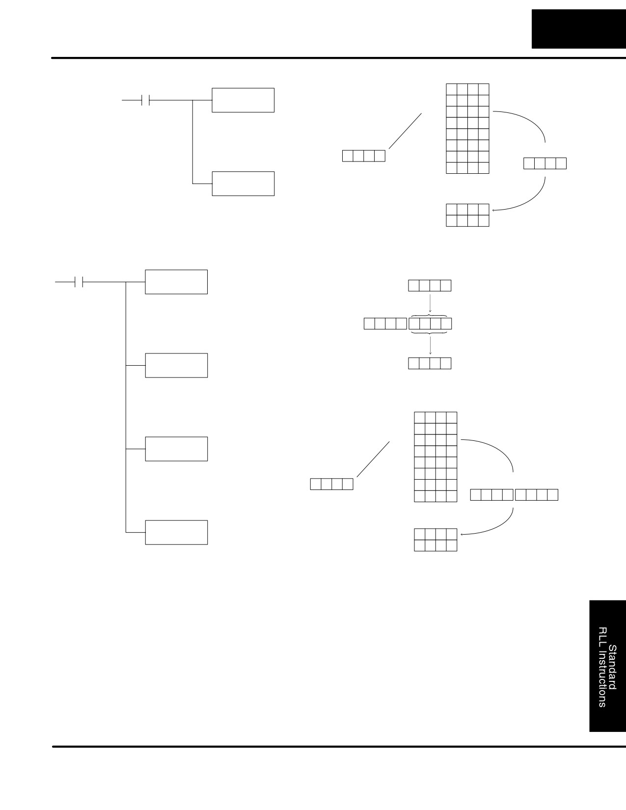
Standard RLL Instructions
5-43
Accumulator / Stack Load and Output Data Instructions
X1
V2076
X
X
X
X
LD
V2077
X
X
X
X
P2000
V2100
2
6
3
5
V1400 (P1400) contains the value 440
V2101
X
X
X
X
HEX. 440 HEX. = 2100 Octal which
contains the value 2635.
V2102
X
X
X
X
V2000
V2103
X
X
X
X
Accumulator
0
4
4
0
V2104
X
X
X
X
2
6
3
5
V2105
X
X
X
X
OUT
V2200
S
S
Copy the data from the lower 16 bits of
the accumulator to V2200.
V2200
2
6
3
5
V2201
X
X
X
X
The following example is identical to the one above with one exception. The LDA
(Load Address) instruction automatically converts the Octal address to Hex.
X1
Load the lower 16 bits of the
LDA
accumulator with Hexadecimal
O 2100
equivalent to Octal 2100 (440)
2
1
0
0
2100 Octal is converted to Hexadecimal
Unused accumulator bits
440 and loaded into the accumulator
are set to zero
Acc.
0
0
0
0
0
4
4
0
OUT
Copy the data from the lower 16 bits of
the accumulator to V2000
0
4
4
0
V 2000
V2000
S
S
V2076
X
X
X
X
V2077
X
X
X
X
V2100
2
6
3
5
LD
V2000 (P2000) contains the value 440
Hex. 440 Hex. = 2100 Octal which
X
X
X
X
P 2000
V2101
contains the value 2635
V2102
X
X
X
X
V2100
V2103
X
X
X
X
Accumulator
0
4
4
0
V2104
X
X
X
X
V2105
X
X
X
X
0
0
0
0
2
6
3
5
S
S
OUT
Copy the data from the lower 16 bits of
the accumulator to V2200
V 2200
V2200
2
6
3
5
V2201
X
X
X
X
DL105 PLC User Manual, 2nd Edition, Rev. A
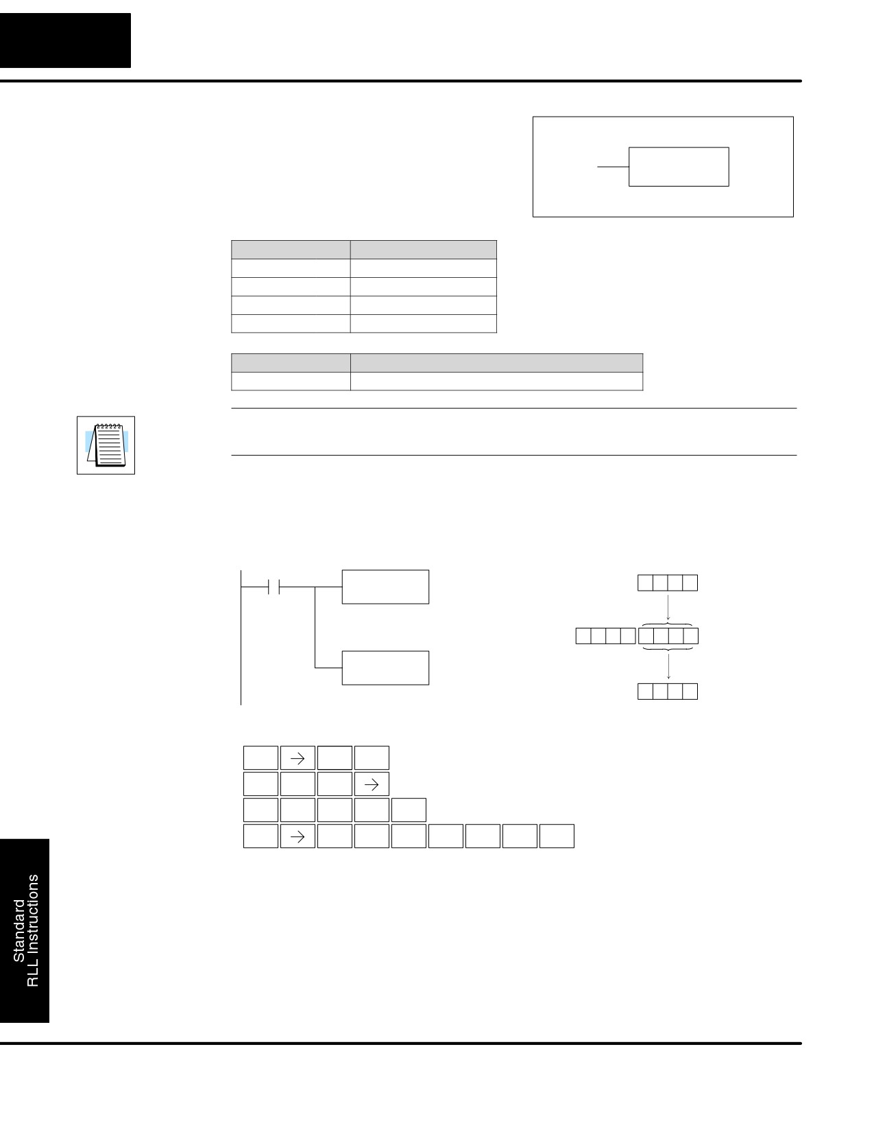
Standard RLL Instructions
5-44
Accumulator / Stack Load and Output Data Instructions
Load
The Load instruction is a 16 bit instruction
(LD)
that loads the value (Aaaa), which is either
a V memory location or a 4 digit constant,
LD
into the lower 16 bits of the accumulator.
A aaa
The upper 16 bits of the accumulator are
set to 0.
Operand Data Type
DL130 Range
A
aaa
V memory
V
All (See page 4-28)
Pointer
P
All V mem. (See page 4-28)
Constant
K
0-FFFF
Discrete Bit Flags
Description
SP76
on when the value loaded into the accumulator by any instruction is zero.
NOTE: Two consecutive Load instructions will place the value of the first load
instruction onto the accumulator stack.
In the following example, when X1 is on, the value in V2000 will be loaded into the
accumulator and output to V2010.
DirectSOFT32
V2000
X1
LD
8
9
3
5
V2000
Load the value in V2000 into
The unused accumulator
the lower 16 bits of the
bits are set to zero
accumulator
0
0
0
0
8
9
3
5
Acc.
OUT
V2010
Copy the value in the lower
8
9
3
5
16 bits of the accumulator to
V2010
V2010
Handheld Programmer Keystrokes
$
B
X
STR
1
SET
L
D
SHFT
ANDST
3
C
A
A
A
ENT
2
0
0
0
GX
V
C
A
B
A
SHFT
ENT
OUT
AND
2
0
1
0
DL105 PLC User Manual, 2nd Edition, Rev. A
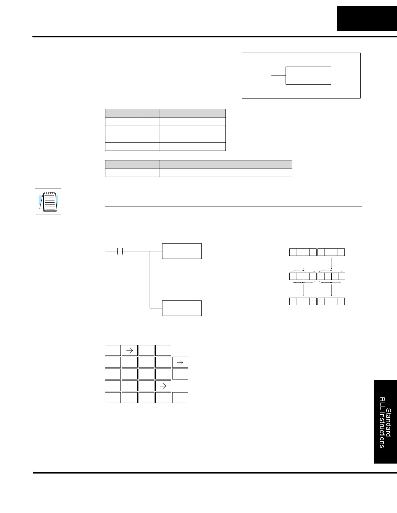
Standard RLL Instructions
5-45
Accumulator / Stack Load and Output Data Instructions
Load Double
The Load Double instruction is a 32 bit
(LDD )
instruction that loads the value (Aaaa),
which is either two consecutive V memory
LDD
locations or an 8 digit constant value, into
A aaa
the accumulator.
Operand Data Type
DL230 Range
A
aaa
V memory
V
All (See page 4-28)
Pointer
P
All V mem. (See page 4-28)
Constant
K
0-FFFFFFFF
Discrete Bit Flags
Description
SP76
on when the value loaded into the accumulator by any instruction is zero.
NOTE: Two consecutive Load instructions will place the value of the first load
instruction onto the accumulator stack.
In the following example, when X1 is on, the 32 bit value in V2000 and V2001 will be
loaded into the accumulator and output to V2010 and V2011.
DirectSOFT32
X1
V2001
V2000
LDD
V2000
6
7
3
9
5
0
2
6
Load the value in V2000 and
V2001 into the 32 bit
accumulator
Acc.
6
7
3
9
5
0
2
6
6
7
3
9
5
0
2
6
OUTD
V2010
V2011
V2010
Copy the value in the 32 bit
accumulator to V2010 and
V2011
Handheld Programmer Keystrokes
$
B
ENT
STR
1
L
D
D
SHFT
ANDST
3
3
C
A
A
A
ENT
2
0
0
0
GX
D
SHFT
OUT
3
C
A
B
A
ENT
2
0
1
0
DL105 PLC User Manual, 2nd Edition, Rev. A
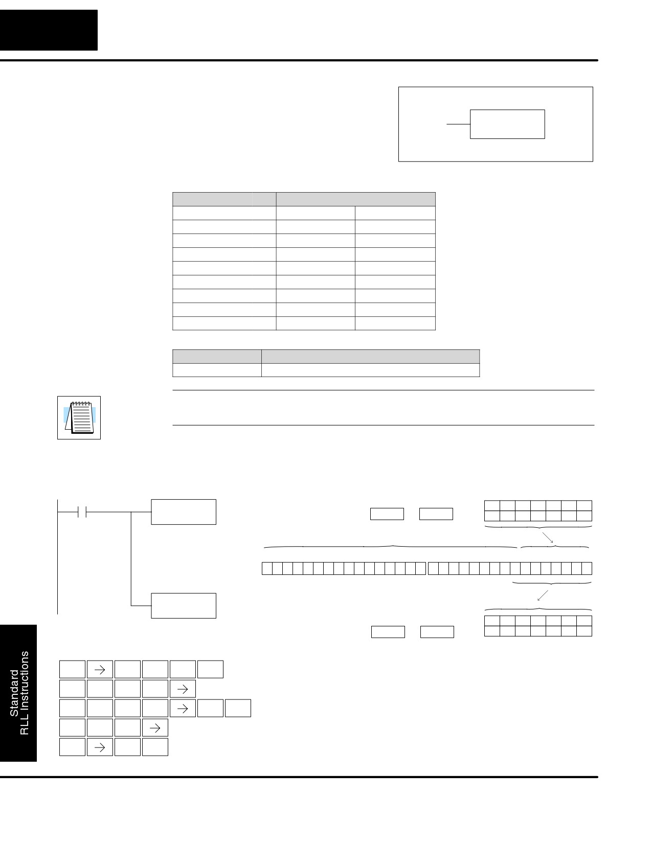
Standard RLL Instructions
5-46
Accumulator / Stack Load and Output Data Instructions
Load
The Load Formatted instruction loads
Formatted
1-32 consecutive bits from discrete
(LDF)
memory locations into the accumulator.
LDF
A aaa
The instruction requires a starting location
K bbb
(Aaaa) and the number of bits (Kbbb) to be
loaded. Unused accumulator bit locations
are set to zero.
Operand Data Type
DL130 Range
A
aaa
bbb
Inputs
X
0-11
--
Outputs
Y
0-7
--
Control Relays
C
0-377
--
Stage Bits
S
0-377
--
Timer Bits
T
0-77
--
Counter Bits
CT
0-77
--
Special Relays
SP
0-117 540-577
--
Constant
K
--
1-32
Discrete Bit Flags
Description
SP76
on when the value loaded into the accumulator by any instruction is zero.
NOTE: Two consecutive Load instructions will place the value of the first load
instruction onto the accumulator stack.
In the following example, when C0 is on, the binary pattern of C10-C16 (7 bits) will
be loaded into the accumulator using the Load Formatted instruction. The lower 7
bits of the accumulator are output to Y0-Y6 using the Out Formatted instruction.
DirectSOFT32
C0
Location
Constant
LDF
C10
C16
C15
C14
C13
C12
C11
C10
K7
C10
K7
OFF
OFF
OFF
ON
ON
ON
OFF
Load the status of 7
consecutive bits (C10-C16)
The unused accumulator bits are set to zero
into the accumulator
31 30 29 28 27 26 25 24 23 22 21 20 19 18 17 16
15 14 13 12 11 10
9
8
7
6
5
4
3
2
1
0
Acc.
0
0
0
0
0
0
0
0
0
0
0
0
0
0
0
0
0
0
0
0
0
0
0
0
0
0
0
0
1
1
1
0
OUTF
Y0
K7
Location
Constant
Y6
Y5
Y4
Y3
Y2
Y1
Y0
Copy the value from the
specified number of bits in
Y0
K7
OFF
OFF
OFF
ON
ON
ON
OFF
the accumulator to Y0 - Y6
Handheld Programmer Keystrokes
$
C
A
SHFT
ENT
STR
2
0
L
D
F
SHFT
ANDST
3
5
C
B
A
H
SHFT
ENT
2
1
0
7
GX
F
SHFT
OUT
5
A
H
ENT
0
7
DL105 PLC User Manual, 2nd Edition, Rev. A