DL105 Micro PLC. User Manual (2003) - page 3
3-10
High-speed Input and Pulse Output Features
Calculating Your
The preset values occupy two data words each. They can range in value from 0000
Preset Values
0000 to 9999 9999, just like the high-speed counter value. All twenty-four values are
absolute values, meaning that each one is an offset from the counter zero value.
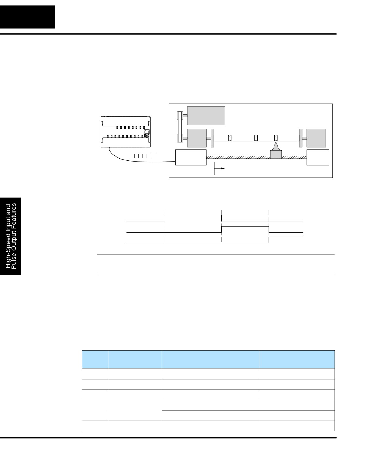
The preset values must be individually derived for each application. In the industrial
lathe diagram below, the PLC monitors the position of the lead screw by counting
pulses. At points A, B, and C along the linear travel, the cutter head pushes into the
work material and cuts a groove.
PLC
Industrial Lathe
A
B C
Counter
Motor
Device
X0, counter clock
Start
The timing diagram below shows the duration of each equal relay contact closure.
Each contact remains on until the next one closes. All go off when the counter resets.
Equal Relays
A
B
C
SP540
SP541
SP542
NOTE: Each successive preset must have a greater value than the previous preset
value. In the industrial lathe example, B>A and C>B.
X Input
The configurable discrete input options for High-Speed Counter Mode are listed in
Configuration
the table below. Input X0 is dedicated for the counter clock input. Inputs X1 and X3
can only be filtered inputs. The section on Mode 60 operation at the end of this
chapter describes programming the filter time constants. Input X2 can be configured
as the counter reset, with or without the interrupt option. The interrupt option allows
the reset input (X2) to cause an interrupt like presets do, but there is no SP relay
contact closure (instead, X2 will be on during the interrupt routine, for 1 scan). Or
finally, X2 may be left simply as a filtered input like X1 and X3.
Input
Configuration
Function
Hex Code
Register
Required
X0
V7634
Counter Clock
0001
X1
V7635
Filtered Input
xx06 (xx = filter time)
X2
V7636
Counter Reset (no interrupt)
0007
Counter Reset (with interrupt)
0107
FIltered Input
xx06 (xx = filter time)
X3
V7637
FIltered Input
xx06 (xx = filter time)
DL105 PLC User Manual, 2nd Edition, Rev. A
3-11
High-Speed Input and Pulse Output Features
Writing Your
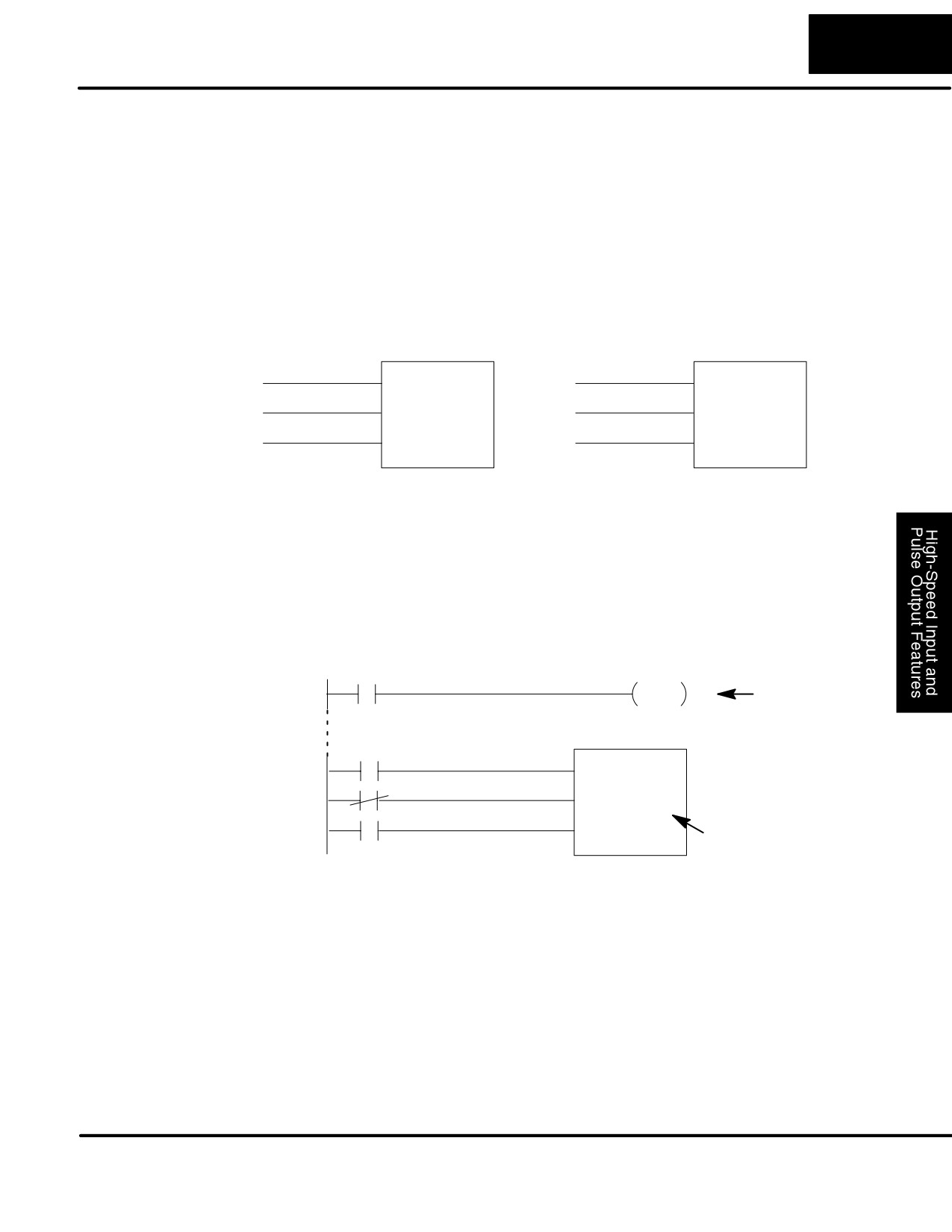
You may recall that the counter instruction is a standard instruction in the DL105
Control Program
instruction set. Refer to the figure below. The mnemonic for the counter is UDC
(up-down counter).The DL105 can have up to 64 counters, labeled CT0 through
CT77. The high speed counter in the HSIO circuit is accessed in ladder logic by using
UDC CT76. It uses counter registers CT76 and CT77 exclusively when the HSIO
mode 10 is active (otherwise, CT76 and CT77 are available for standard counter
use). The HSIO counter needs two registers because it is a double-word counter. It
has three inputs as shown. The first input (Enable) allows counting when active. The
middle input (Preload) allows you to change the current count. The bottom signal is
the reset. The preload input must be off while the counter is counting.
Standard Counter Function
HSIO Counter Function
UP Count
UDC CTxx
Enable Input
UDC CT76
DOWN Count
Preload Input
Kxxxxxxxx
Kxxxxxxxx
Reset Input
Reset Input
D Counts UP and DOWN
D Counts UP only
D Preload counter by write to value
D Can use Preload input to change count
D Reset input is internal only
D Reset may be internal or external
The next figure shows how the HSIO counter will appear in a ladder program. Note
that the Enable Interrupt (ENI) command must execute before the counter value
reaches the first preset value. We do this at powerup by using the first scan relay.
When using the counter but not the presets and interrupt, we can omit the ENI.
DirectSOFT32
SP0
ENI
Required
Enable Input
UDC CT76
Preload Input
Kxxxxxxxx
Reset Input
Preset Range:
1-99999999
When the enable input is energized, the high-speed counter will respond to pulses
on X0 and increment the counter at CT76 - CT77. The reset input contact behaves in
a logical OR fashion with the physical reset input X2 (when selected). So,the high
speed counter can receive a reset form either the contact(s) on the reset rung in the
ladder, OR the external reset X2 if you have configured X2 as an external reset.
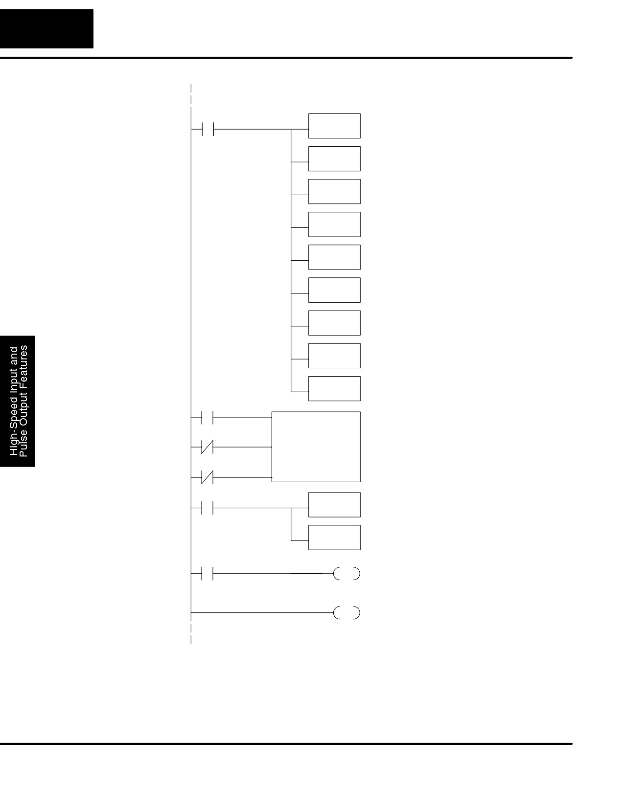
Program Example: The following example is the simplest way to use the high-speed counter, which
Counter Without
does not use the presets and special relays in the interrupt routine. The program
Preset
configures the HSIO circuit for Mode 10 operation, so X0 is automatically the counter
clock input. It uses the Compare-double (CMPD) instruction to cause action at
certain count values. Note that this allows you to have more than 24 “presets”.Then it
configures X2 to be the external reset of the counter.
DL105 PLC User Manual, 2nd Edition, Rev. A
3-12
High-speed Input and Pulse Output Features
Program
DirectSOFT32
Example Cont’d
First Scan Only
SP0
Load constant K10 into the accumulator. This
LD
selects Mode 10 as the HSIO mode.
K10
Mode 10
Output the constant K10 to V7633, the
OUT
location of HSIO Mode select register.
V7633
Load the constant required to configure X0 as
LD
the counter clock.
K1
Output the constant K1 to V7634, the location of
OUT
the setup parameter for X0.
V7634
Load the constant required to configure X2 as
Configure
LD
an external reset without interrupt.
Inputs
K7
Output the constant K7 to V7636, the location of
OUT
the setup parameter for X2.
V7636
Load the constant required to configure inputs
LD
as filtered inputs.
K1006
Output the constant K1006 to V7635, the location
OUT
of setup parameter for X1.
V7635
Output the constant K1006 to V7637, the location
OUT
of setup parameter for X3.
V7637
SP1
UDC
CT76
CT76 is the HSIO counter. The first rung’s SP1
always enables the counter. The preload contact in
SP1
the middle is always off. The third rung’s Reset
Kxxxxxxxx
input is always off, because we will use the
external reset.
SP1
SP1
Load the current count of the HSIO counter in
LDD
V1076 and V1077 into the accumulator
V1076
Use the Compare-double instruction to compare
CMPD
the double word in the accumulator to the constant
K309482
K309482
SP62
Y0
OUT
The execution of the above CMPD instruction turns
on special relay contact SP62 if the current count
is greater than the comparison number (K309482).
END
END coil marks the end of the main program.
The compare double instruction above uses the current count of the HSIO counter to
turn on Y0. This technique can make more than 24 comparisons, but it is scan-time
dependent. However, use the 24 built-in presets with the interrupt routine if your
application needs a very fast response time, as shown in the next example.
DL105 PLC User Manual, 2nd Edition, Rev. A
3-13
High-Speed Input and Pulse Output Features
Counter With
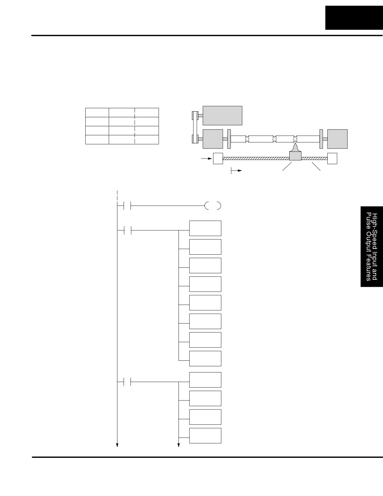
The following example shows how to program the HSIO circuit to trigger on three
Presets
preset values. You may recall the industrial lathe example from the beginning of this
chapter. This example program shows how to control the lathe cutter head to make
Program Example
three grooves in the work-piece at precise positions. When the lead screw turns, the
counter device generates pulses which the DL105 can count. The three preset
variables A, B, and C represent the positions (number of pulses) corresponding to
each of the three grooves.
Preset Data
A
V2320
0000
1500
Industrial Lathe
B
V2322
0000
3780
C
V2324
0000
4850
A
B C
V2326
0000
FFFF
I/O
X4 - Cutter head extended
Counter
Assignments
X5 - Cutter head retracted
Device
Y0 - Lead screw motor
Start
Y1 - Cutter head solenoid
Cutter head
Lead screw
DirectSOFT32
SP0
Enable Interrupts before reaching a preset
ENI
generates an interrupt. Special Relay SP0 is on
during the first CPU scan.
SP0
Load constant K10 into the accumulator. This
LD
selects Mode 10 as the HSIO mode.
K10
Output this address to V7633, the location of
OUT
V7633
HSIO Mode select register.
Load the constant required to configure X0 as
LD
the counter clock.
K1
Output the constant K1 to V7634, the location of
OUT
the setup parameter for X0.
V7634
Load the constant required to configure X2 as
LD
Select Mode 10
an external reset with interrupt.
K107
Output the constant to V7636, the location of the
OUT
setup parameter for X2.
V7636
Load the octal address O2320 into the
LDA
accumulator. This instruction automatically
O2320
converts the address into hex.
OUT
Output this address to V7630, the location of
V7630
the pointer to the Preset Table.
SP0
Load the preset A value into the accumulator.
LDD
K1500
Load Presets
Output the accumulator contents to the memory
OUTD
location for preset 1.
V2320
Load the preset B value into the accumulator.
LDD
K3780
Output the accumulator contents to the memory
OUTD
V2322
location for preset 2.
DL105 PLC User Manual, 2nd Edition, Rev. A
3-14
High-speed Input and Pulse Output Features
Load the preset C value into the accumulator.
LDD
K4850
Output the accumulator contents to the memory
OUTD
location for preset 3.
V2324
Load the constant Kffff into the accumulator. This
LDD
value represents the end of the preset list.
Kffff
Output the accumulator contents to the memory
OUTD
V2326
location for preset 4 (end of preset marker).
SP1
UDC
CT76
CT76 is the HSIO counter. The first rung’s SP1
always enables the counter. The preload contact in
SP1
the middle is off (unused in this example).
Kxxxxxxxx
SP1
The third rung’s Reset input is normally off,
because we will use the external reset. You can
SP0
optionally reset the counter value on each powerup
using the SP0 contact.
X4
Y1
RST
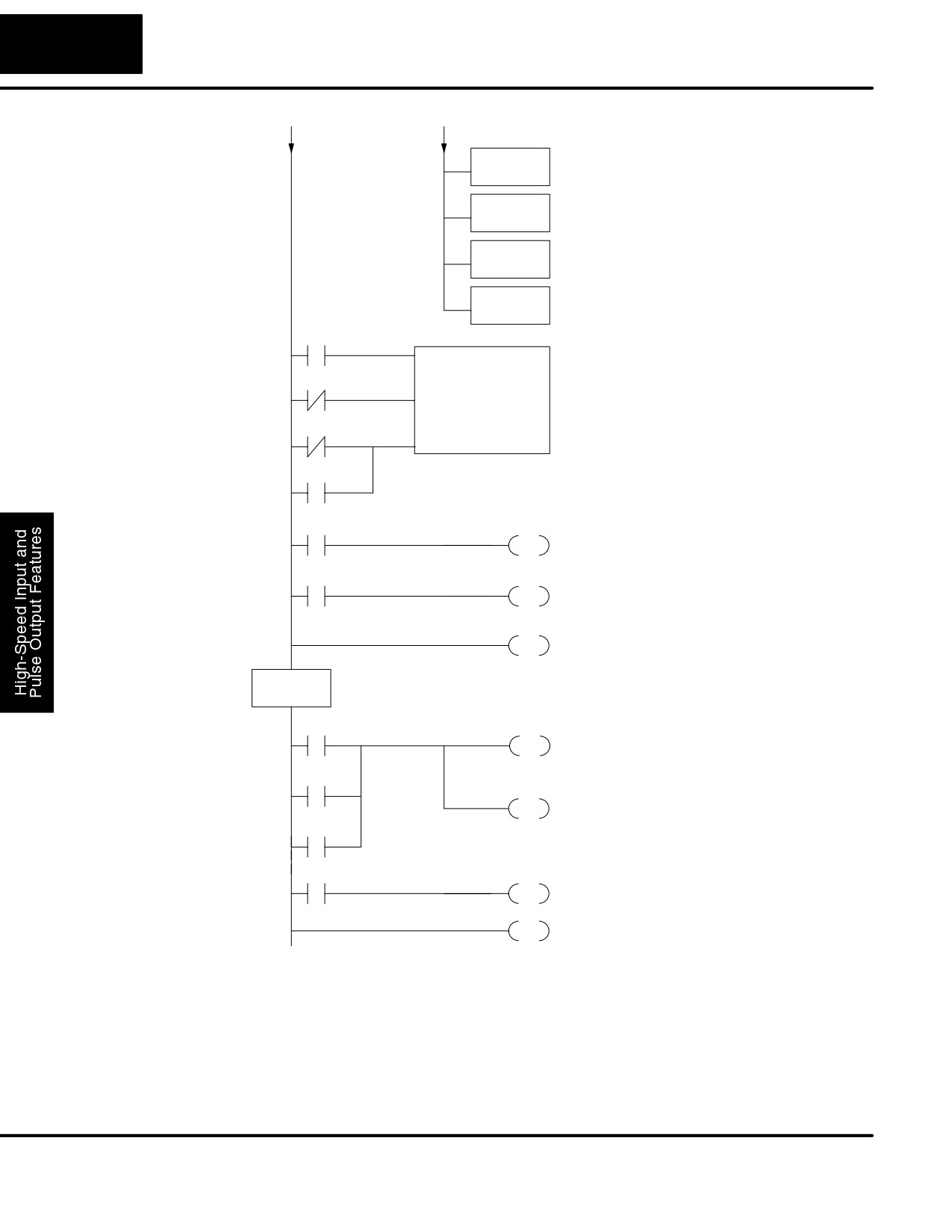
Input X4 energizes when the groove has finished
cutting. So, we retract the cutter head.
X5
Y0
SET
Turn lead screw on again, after cutter head has
retracted.
END
END coil marks the end of the main program.
The INT label marks the beginning of the interrupt
INT
O0
service routine program.
SP540
Preset 1
Y0
Inside the interrupt service routine, we turn OFF the
RST
lead screw motor immediately.
SP541
These special “equal” relays turn on individually as
Preset 2
Y1
the corresponding preset is reached. In this
SET
application, each results in the cutting of a groove
SP542
(Y1), so they are logically ORed together.
Preset 3
X2
C10
SET
Input X2 will be energized inside the interrupt
routine if X2 external interrupt was the source.
IRT
Return from the interrupt service routine.
Some applications will require a different type of action at each preset. It is possible
for the interrupt routine to distinguish one preset event from another, by turning on a
unique output for each equal relay contact SPxxx. We can determine the source of
the interrupt by examining the equal relay contacts individually, as well as X2. The X2
contact will be on (inside the interrupt routine only) if the interrupt was caused by the
external reset, X2 input.
DL105 PLC User Manual, 2nd Edition, Rev. A
3-15
High-Speed Input and Pulse Output Features
Counter With
The following example shows how you can preload the current count with another
Preload
value. When the preload command input (X4 in this example) is energized, we
disable the counter from counting with C0. Then we write the value K3000 to the
Program Example
count register (V1076-V1077). By pulsing C1 on, we preload the current count of the
counter with K3000. When the preload command (X4) is turned off, the counter
resumes counting any pulses, but now starting from K3000.
DirectSOFT32
SP0
Load constant K10 into the accumulator. This
LD
selects Mode 10 as the HSIO mode.
K10
Output this address to V7633, the location of
Select Mode 10
OUT
HSIO Mode select register.
V7633
Load the constant required to configure X0 as
LD
the counter clock.
K1
Output the constant K1 to V7634, the location of
OUT
the setup parameter for X0.
V7634
Load the constant required to configure X2 as
LD
an external reset with interrupt.
K107
Output the constant to V7636, the location of the
OUT
setup parameter for X2.
V7636
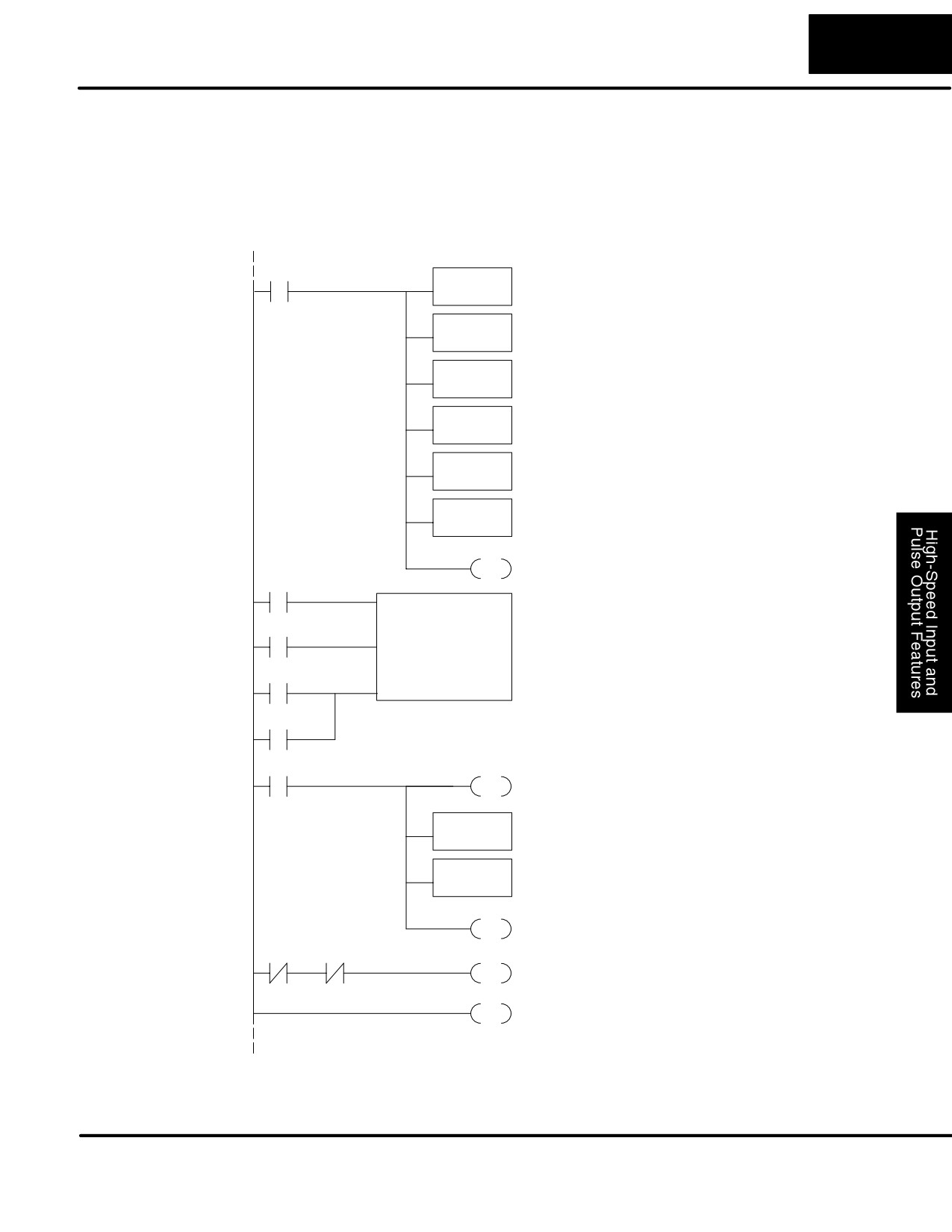
C0
SET
Set C0 on at powerup to enable counting.
C0
UDC
CT76
CT76 is the HSIO counter. The first rung’s C0
contact enables the counter. The preload contact
C1
in the middle is off until the logic near the end of
K99999999
this program turns it on.
C2
The third rung’s Reset input is normally off,
because we will use the external reset. You can
SP0
optionally reset the counter value on each powerup
using the SP0 contact.
X4
C0
When the preload request is made, the user turns
on X4. First we disable counting by resetting C0,
RST
the counter’s enable input.
Load the BCD value K3000 into the
LDD
accumulator.
K3000
Output the constant to V1076/V1077, the location
OUTD
of the accumulated count for CT76.
V1076
C1
Generate a preload counter input pulse, which
PD
causes the counter to preload from V1076-V1077.
C0
C1
C0
Enable the counter by setting C0, when the
SET
preolad pulse on C1 has occurred (C1 is off).
END
END coil marks the end of the main program.
DL105 PLC User Manual, 2nd Edition, Rev. A
3-16
High-speed Input and Pulse Output Features
Troubleshooting
If you’re having trouble with Mode 10 operation, please study the following
Guide for Mode 10
symptoms and possible causes. The most common problems are listed below.
Symptom: The counter does not count.
Possible causes:
1. Field sensor and wiring - Verify that the encoder, proximity switch,or
counter actually turns on and illuminates the status LED for X0. The
problem could be due to sinking-sourcing wiring problem, etc. Remember
to check the signal ground connection. Also verify that the pulse on-time is
long enough for the PLC to recognize it.
2. Configuration - make sure all of the configuration parameters are correct.
V7633 must be set to 10, and V7634 must be set to 1 to enable the HSIO
counter mode.
3. Stuck in reset - check the input status of the reset input, X2. If X2 is on, the
counter will not count because it is being held in reset.
4. Ladder program - make sure you are using counter CT76 in your
program. The top input is the enable signal for the counter. It must be on
before the counter will count. The middle input is the preload input and must
be off for the counter to count. The bottom input is the counter reset, and
must be off during counting.
Symptom: The counter counts but the presets do not function.
Possible causes:
1. Configuration - Ensure the preset values are correct. The presets are
32-bit BCD values having a range of 0 to 99999999. Make sure you write all
32 bits to the reserved locations by using the LDD and OUTD instructions.
Use only even-numbered addresses, from V2320 to V2376. If using less
than 24 presets, be sure to place “0000FFFF” in the location after the last
preset used.
2. Interrupt routine - Only use Interrupt #0. Make sure the interrupt has been
enabled by executing an ENI instruction prior to needing the interrupt. The
interrupt routine must be placed after the main program, using the INT label
and ending with an interrupt return IRT.
3. Special relays - Check the special relay numbers in your program. Use
SP540 for Preset 1, SP541 for Preset 2, etc. Remember that only one
special equal relay contact is on at a time. When the counter value reaches
the next preset, the SP contact which is on now goes off and the next one
turns on.
Symptom: The counter counts up but will not reset.
Possible causes:
1. Check the LED status indicator for X2 to make sure it is active when you
want a reset. Or, if you are using an internal reset, use the status mode of
DirectSOFT32 to monitor the reset input to the counter.
DL105 PLC User Manual, 2nd Edition, Rev. A
3-17
High-Speed Input and Pulse Output Features
Mode 20: Quadrature Counter
Purpose
The counter in the HSIO circuit can count two quadrature signal pulses instead of a
single pulse train (mode 10 operation). Quadrature signals are commonly generated
from incremental encoders, which may be rotary or linear. The quadrature counter
has a range from 0 to 99999999, and can count at up to a 5 kHz rate, using CT76 and
CT77. Unlike Mode 10 operation, the quadrature counter can count UP or DOWN,
but does not feature automated preset values or “interrupt on external reset”
capability. However, you have the standard ladder instruction preset of CT76.
Functional Block
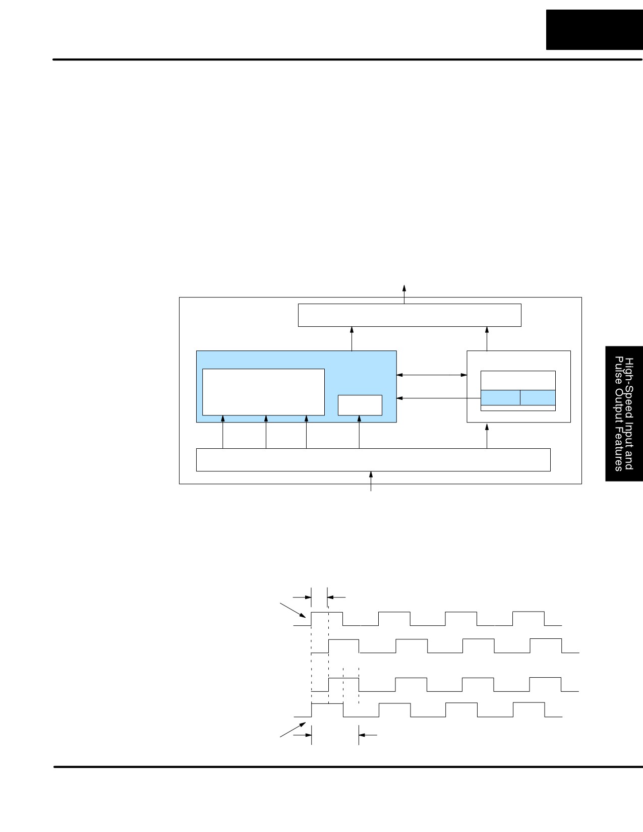
The diagram below shows HSIO functionality in Mode 20. When the lower byte of
Diagram
HSIO Mode register V7633 contains a BCD “20”, the quadrature counter in the HSIO
circuit is enabled. Input X0 is dedicated to the Phase A quadrature signal, and input
X1 receives Phase B signal. X2 is dedicated to reset the counter to zero value when
energized. X3 can only be a regular filtered input in Mode 20.
DL105
Output Circuit
PLC
Y0, Y1
Y2 - Y7
HSIO
CPU
I/O data
COUNTER
VĆmemory
Mode Select
Phase
Phase
V7633
xx20
FILTER
A
B Reset
X0
X1
X2
X3
X4- X11
Input Circuit
Quadrature
Quadrature encoder signals contain position and direction information, while their
Encoder Signals
frequency represents speed of motion. Phase A and B signals shown below are
phase-shifted 90 degrees, thus the quadrature name. When the rising edge of
Phase A precedes Phase B’s leading edge (indicates clockwise motion by
convention), the HSIO counter counts UP. If Phase B’s rising edge precedes Phase
A’s rising edge (indicates counter-clockwise motion), the counter counts DOWN.
90° phase shift
Leading Edge Signal
Clockwise sequence
Phase A
Phase B
Counterclockwise sequence
Phase A
Phase B
one cycle
Leading Edge Signal
DL105 PLC User Manual, 2nd Edition, Rev. A
3-18
High-speed Input and Pulse Output Features
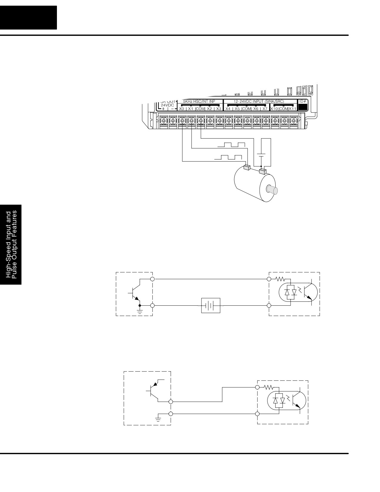
A general wiring diagram for encoders to the DL105 in HSIO Mode 20 is shown
Wiring Diagram
below. Encoders with sinking outputs (NPN open collector) are probably the best
choice for interfacing. If the encoder sources to the inputs, it must output 12 to 24
VDC. Note that encoders with 5V sourcing outputs will not work with DL105 inputs.
Signal Common
Phase B
+
DC Supply
Phase A
-
Encoder Input Wiring
Encoder
Interfacing to
The DL105’s DC inputs are flexible in that they detect current flow in either direction,
Encoder Outputs
so they can be wired to an encoder with either sourcing or sinking outputs. In the
following circuit, an encoder has open-collector NPN transistor outputs. It sinks
current from the PLC input point, which sources current. The power supply can be
the +24VDC auxiliary supply or another supply (+12VDC or +24VDC), as long as the
input specifications are met.
Encoder Output,
(one phase)
Phase A or B Input
Output
Input
(sinking)
(sourcing)
12Ć24 VDC Supply
Ground
-
+
Common
In the next circuit, an encoder has open-emitter PNP transistor outputs. It sources
current to the PLC input point, which sinks the current back to ground. Since the
encoder sources current, no additional power supply is required. However, note that
the encoder output must be 12 to 24 volts (5V encoder outputs will not work).
Encoder Output,
(one phase)
Phase A or B Input
+12 to 24VDC
Input
(sinking)
Output (sourcing)
Ground
Common
DL105 PLC User Manual, 2nd Edition, Rev. A
3-19
High-Speed Input and Pulse Output Features
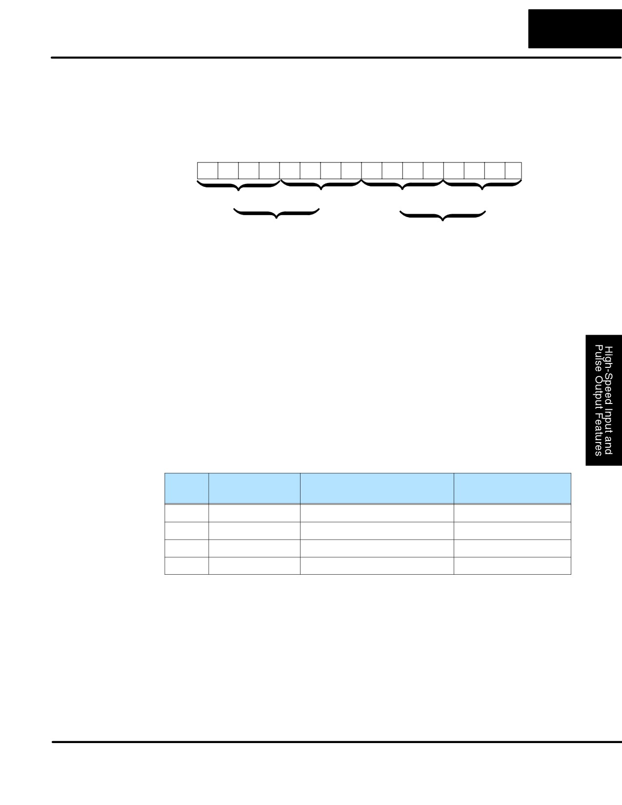
Recall that V7633 is the HSIO Mode Select register. Refer to the diagram below. Use
Setup for Mode 20
BCD 20 in the lower byte to select High-Speed Counter Mode. Use BCD 00 or 20 in
the upper byte as required. Combine the two bytes into a data word “xx20”, for writing
to V7633.
Memory Location V7633
Bits
15
14
13
12
11
10
9
8
7
6
5
4
3
2
1
0
0
0
1
0
0
0
0
0
0
0
1
0
0
0
0
0
2
0
2
0
Miscellaneous Setup (BCD)
HSIO Mode Setup (BCD)
00 = Power Up in Previous Mode
20 = Power Up in Run Mode Always
20 = Quadrature Counter
Choose the most convenient method of programming V7633 from the following:
S Include load and out instructions in your ladder program
S DirectSOFT32’s memory editor
S Use the Handheld Programmer D2-HPP
We recommend using the first method above so that the HSIO setup becomes an
integral part of your application program. An example program later in this section
shows how to to this.
X Input
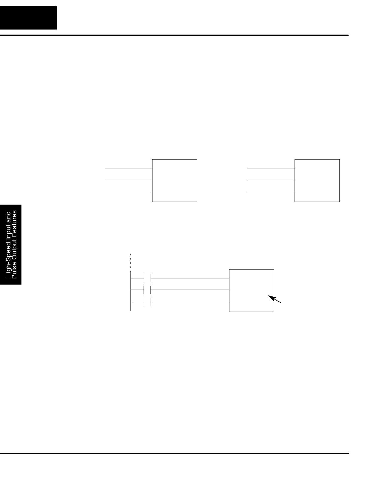
The configurable discrete input options for High-Speed Counter Mode are listed in
Configuration
the table below. Input X0 is dedicated for Phase A, and input X1 is for Phase B. Input
X2 is the reset input to the quadrature counter, but it does not cause an interrupt.
Input X3 can only be a filtered input. The section on Mode 60 operation at the end of
this chapter describes programming the filter time constants.
Input
Configuration
Function
Hex Code
Register
Required
X0
V7634
Phase A
0012
X1
V7635
Phase B
0000
X2
V7636
Counter Reset (no interrupt)
0007
X3
V7637
Filtered Input
xx06 (xx = filter time)
DL105 PLC User Manual, 2nd Edition, Rev. A
3-20
High-speed Input and Pulse Output Features
Writing Your
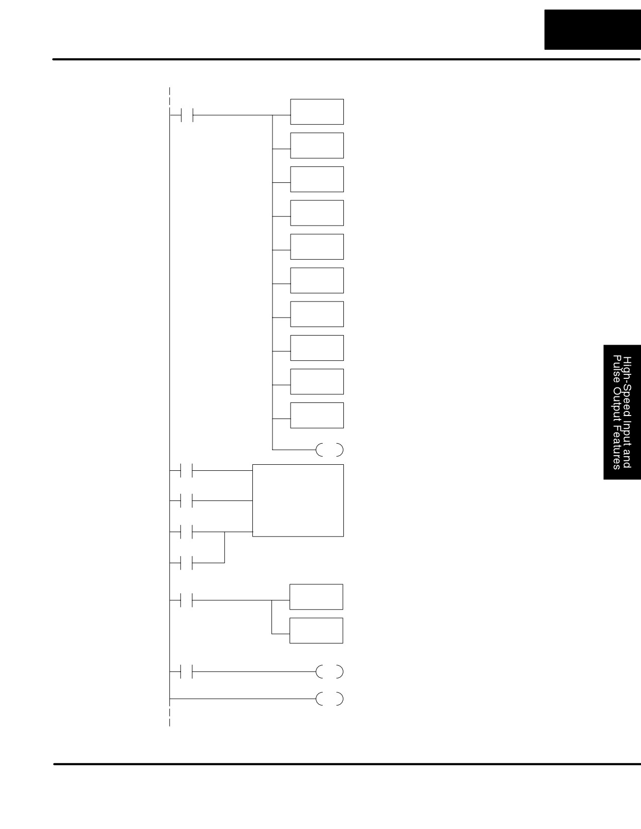
You may recall that the Up-Down counter instruction is standard in the DL105
Control Program
instruction set. Refer to the figure below. The mnemonic for the counter is UDC
(up-down counter).The DL105 can have up to 64 counters, labeled CT0 through
CT77. The quadrature counter in the HSIO circuit is accessed in ladder logic by
using UDC CT76. It uses counter registers CT76 and CT77 exclusively when the
HSIO mode 20 is active (otherwise, CT76 and CT77 are available for standard
counter use). The HSIO counter needs two registers because it is a double-word
counter. It also has three inputs as shown, but they are redefined. The first input is
the enable signal, the middle is a preload (write), and the bottom is the reset. The
enable input must be on before the counter will count. The preload input allows you
to write a new value to the current count. The enable input must be off during a
preload.
Standard Counter Function
HSIO Counter Function
UP Count
UDC CTxx
Enable Input
UDC CT76
DOWN Count
Preload Input
Kxxxxxxxx
Kxxxxxxxx
Reset Input
Reset Input
D Counts UP and DOWN
D Counts UP and DOWN (from X0, X1)
D Preload counter by write to value
D Can use Preload input to change count
D Reset input is internal only
D Reset may be internal or external
The next figure shows the how the HSIO quadrature counter will appear in a ladder
program.
Enable Input
UDC CT76
Preload Input
Kxxxxxxxx
Reset Input
Preset Range:
-8,388,608 to
+8,388,607
When the enable input is energized, the counter will respond to quadrature pulses
on X0 and X1, incrementing or decrementing the counter at CT76 - CT77. The reset
input contact behaves in a logical OR fashion with the physical reset input X2. This
means the quadrature counter can receive a reset from either the contact(s) on the
reset rung in the ladder, OR the external reset X2.
Quadrature
Since presets are not available in quadrature counting, this mode is best suited for
simple counting and measuring. The example program on the following page shows
Counter w/Preload
how to configure the quadrature counter. The program configures the HSIO circuit
Program Example
for Mode 20 operation, so X0 is Phase A and X1 is Phase B clock inputs.
DL105 PLC User Manual, 2nd Edition, Rev. A
3-21
High-Speed Input and Pulse Output Features
Program
DirectSOFT32
Example Cont’d
SP0
Load constant K20 into the accumulator. This selects
LD
Mode 20 as the HSIO mode.
K20
Output this address to V7633, the location of the HSIO
Select Mode 20
OUT
Mode select register.
V7633
Load the constant required to configure X0 as Phase A
LD
input.
K12
Output the constant to V7634, the location of the setup
OUT
register for X0.
V7634
Load the constant required to configure X1 as Phase B
LD
input.
K0
Output the constant to V7635, the location of the setup
OUT
register for X1.
V7635
Load the constant required to configure X2 as an external
LD
reset.
K7
Output the constant to V7636, the location of the setup
OUT
register for X2.
V7636
Load the constant required to configure X3 as a filtered
LD
discrete input with a 10 mS time constant.
K1006
Output the constant to V7637, the location of the setup
OUT
register for X3.
V7637
C0
SET
Set C0 on at powerup to enable counting.
C0
UDC
CT76
CT76 is the HSIO quadrature counter. The first rung’s SP1
always enables the counter. The preload contact in the
C1
middle is controlled by the logic below this counter
Kxxxxxxxx
instruction.
C2
The third rung’s Reset input is normally off,
because we will use the external reset. You can
SP0
optionally reset the counter value on each powerup
using the SP0 contact.
SP1
Load the current value of the counter into the accumulator
LDD
on each scan.
V1076
Compare the value in the accumulator with the constant
Select Mode 20
CMPD
K44292. If they are equal, the SP61 contact will be
K44292
turned on.
SP61
Y0
Set Y1 to ON when the counter reaches our
SET
comparison value.
END
END coil marks the end of the main program..
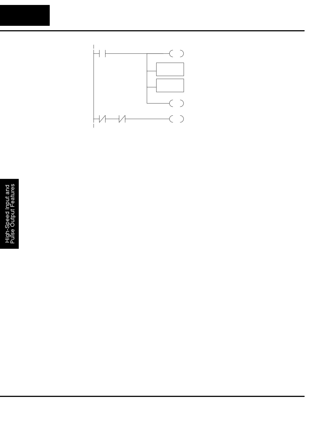
To preload the counter, just add the following example rungs to the program above.
DL105 PLC User Manual, 2nd Edition, Rev. A
3-22
High-speed Input and Pulse Output Features
Counter Preload
X4
C0
When the preload request is made, the user turns
Program Example
RSTon X4. First we disable counting by resetting C0,
the counter’s enable input.
Load the BCD value K3000 into the
LDD
Preload counter
accumulator.
K3000
Output the constant to V1076/V1077, the location
OUTD
V1076
of the accumulated pulse count.
C1
PDcauses the counter to preload from V1076-ich
V1077.
C0
C1
C0
Enable the counter by setting C0, when the
SET
preolad pulse on C1 has occurred (C1 is off).
Troubleshooting
If you’re having trouble with Mode 20 operation, please study the following
Guide for Mode 20
symptoms and possible causes. The most common problems are listed below.
Symptom: The counter does not count.
Possible causes:
1. Field sensor and wiring - Verify that the encoder or other field device
inputs actually turn on and illuminates the status LEDs for X0 and X1. A
standard incremental encoder will visibly, alternately turn on the LEDs for
X0 and X1 when rotating slowly (1 RPM). Or, the problem could be due to a
sinking-sourcing wiring problem, etc. Remember to check the signal
ground connection. Also verify that the pulse on-time, duty cycle, voltage
level, and frequency are within the input specifications.
2. Configuration - make sure all of the configuration parameters are correct.
V7633 must be set to 20, and V7634 must be set to “0012” to enable the
Phase A input, and V7635 must be set to “0000” to enable the Phase B
input.
3. Stuck in reset - check the input status of the reset input, X2. If X2 is on, the
counter will not count because it is being held in reset.
4. Ladder program - make sure you are using counter CT76 in your
program. The top input is the enable signal for the counter. It must be on
before the counter will count. The middle input is the preload input and must
be off for the counter to count. The bottom input is the counter reset, and
must be off during counting.
Symptom: The counter counts in the wrong direction (up instead of down, and visa-versa).
Possible causes:
1. Channel A and B assignment - It’s possible that Channel A and B
assignments of the encoder wires is backwards from the desired
rotation/counting orientation. Just swap the X0 and X1 inputs, and the
counting direction will be reversed.
Symptom: The counter counts up and down but will not reset.
Possible causes:
1. Check the LED status indicator for X2 to make sure it is active when you
want a reset. Also verify the configuration register V7636 for X2 is set to 7.
Or, if you are using an internal reset, use the status mode of DirectSOFT32
to monitor the reset input to the counter.
DL105 PLC User Manual, 2nd Edition, Rev. A
3-23
High-Speed Input and Pulse Output Features
Mode 30: Pulse Output
Purpose
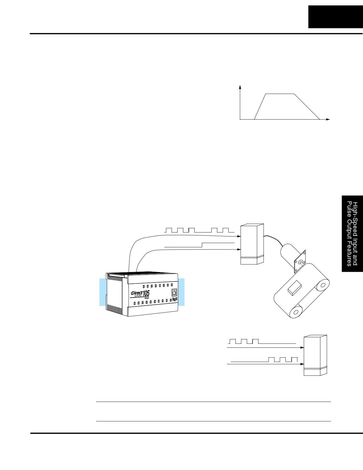
The HSIO circuit in Mode 30 generates
Trapezoidal Profile
output pulse trains suitable for open-loop
Velocity
control of a single-axis motion positioning
system. It generates pulse
(stepper
increment) and direction signals which
Accel
Decel
you can connect to motor drive systems
and perform various types of motion
control. Using Mode 30 Pulse Output, you
Time
can select from three profile types:
S Trapezoidal - Accel Slope to Target Velocity to Decel Slope
S Registration - Velocity to Position Control on Interrupt (also used for
home search moves)
S Velocity Control - Speed and Direction only
The HSIO circuit becomes a high-speed pulse generator (up to 7 kHz) in Mode 30.
By programming acceleration and deceleration values, position and velocity target
values, the HSIO function automatically calculates the entire motion profile. The
figure below shows the DL105 generating pulse and direction signals to the drive
amplifier of a stepper positioning system. The pulses accomplish the profile
independently and without interruption to ladder program execution in the CPU.
Pulse
Stepper
Motor
Direction
DL105 Micro PLC
Drive
Amplifier
In the figure above, the DL105 generates
CCW Pulse
pulse and direction signals. Each pulse
represents the smallest increment of
motion to the positioning system (such as
CW Pulse
one step or micro-step to a stepper
system). Alternatively, the HSIO Pulse
Output Mode may be configured to deliver
counter clock-wise (CCW) and clock-wise
Drive
(CW) pulse signals as shown to the right.
Amplifier
NOTE: The pulse output is designed for open loop stepper motor systems. This, plus
its minimum velocity of 40 pps make it unsuitable for servo motor control.
DL105 PLC User Manual, 2nd Edition, Rev. A
3-24
High-speed Input and Pulse Output Features
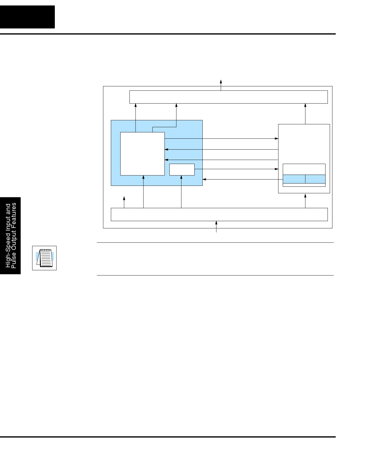
Functional Block The diagram below shows HSIO functionality in Mode 30. When the lower byte of
Diagram
HSIO Mode register V7633 contains a BCD “30”, the pulse output capability in the
HSIO circuit is enabled. The pulse outputs use Y0 and Y1 terminals on the output
connector. Remember that the outputs can only be DC type to operate.
DL105
Output Circuit
PLC
Y0
Y1
(Pulse / CW)
(Direction / CCW)
Y2 - Y7
HSIO
X0 Profile Complete
CPU
PULSE GEN.
Y0 Start Profile
Y1 Preload Position Value
X1, X3 Filtered Inputs
Interrupt
FILTER
VĆmemory
Mode Select
V7633
xx30
not used
X0
X2
X1, X3
X4- X11
Input Circuit
IMPORTANT NOTE: In Pulse Output Mode, X0, Y0, and Y1 references are
redefined or are used differently in two ways. Physical references refer to terminal
screws, while logical references refer to I/O references in the ladder program.
Please read the items below to understand this very crucial point.
Notice the I/O point assignment and usage in the above diagram:
S Physical input X0 is not used, so the terminal screw will not be wired.
However, the HSIO function uses logical reference X0 for “Profile
Complete” contact, which is available for ladder program use.
S X1 and X3 can only be filtered inputs in Pulse Output Mode, and they
are available as input contacts to the ladder program.
S X2 behaves as an external interrupt to the pulse generator for
registration profiles. In other profile modes, it can be used as a filtered
input just like X1 and X3 (registration mode configuration shown above).
S References “Y0” and “Y1” are used in two different ways. At the output
connector, Y0 and Y1 terminals deliver the pulses to the motion system.
The ladder program uses logical references Y0 and Y1 to initiate “Start
Profile” and “Load Position Value” HSIO functions in Mode 30.
Hopefully, the above discussion will explain why some I/O reference names have
dual meanings in Pulse Output Mode. Please read the remainder of this section
with care, to avoid confusion about which actual I/O function is being discussed.
DL105 PLC User Manual, 2nd Edition, Rev. A
3-25
High-Speed Input and Pulse Output Features
Wiring Diagram
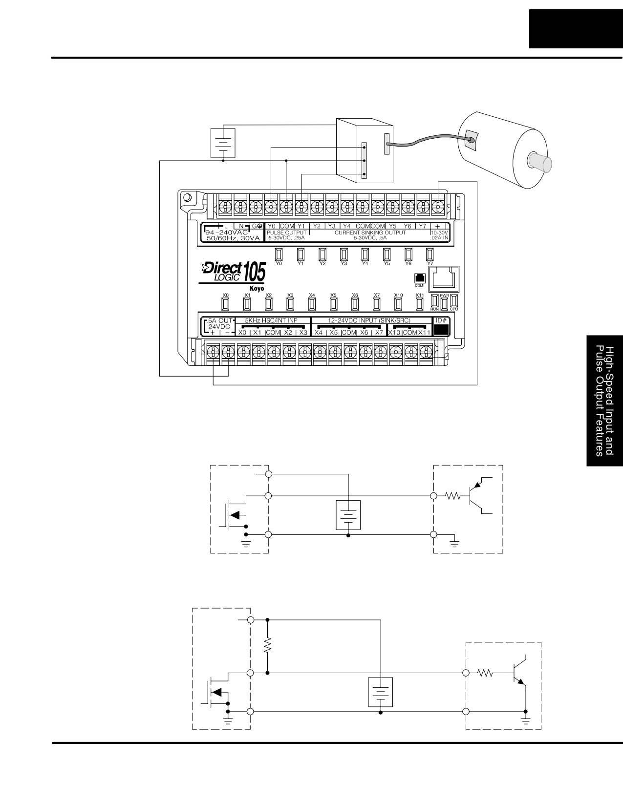
The generalized wiring diagram below shows pulse outputs Y0 and Y1 connected to
the drive amplifier inputs of a motion control system.
Pulse Output Wiring
Power Input
Amplifier
Motor
+
Pulse
-
Signal Common
Direction
Interfacing to
The pulse signals from Y0 and Y1 outputs will typically go to drive input circuits as
Drive Inputs
shown above. Remember that the DL105’s DC outputs are sinking-only. It will be
helpful to locate equivalent circuit schematics of the drive amplifier. The following
diagram shows how to interface to a sourcing drive input circuit.
Y0, Y1 Pulse Output
Drive Input
Power
+DC pwr
+V
Output
Input
(sinking)
+
(sourcing)
Common
-
Ground
The following circuit shows how to interface to a sinking drive input using a pullup
resistor. Please refer to Chapter 2 to learn how to calculate and install Rpullup.
Y0, Y1 Pulse Output
Power
+DC pwr
Drive Input
R
pullup
(sourcing)
(sinking)
Output
Input
R input
+
(sinking)
Supply
Common
-
Ground
DL105 PLC User Manual, 2nd Edition, Rev. A
3-26
High-speed Input and Pulse Output Features
Motion Profile
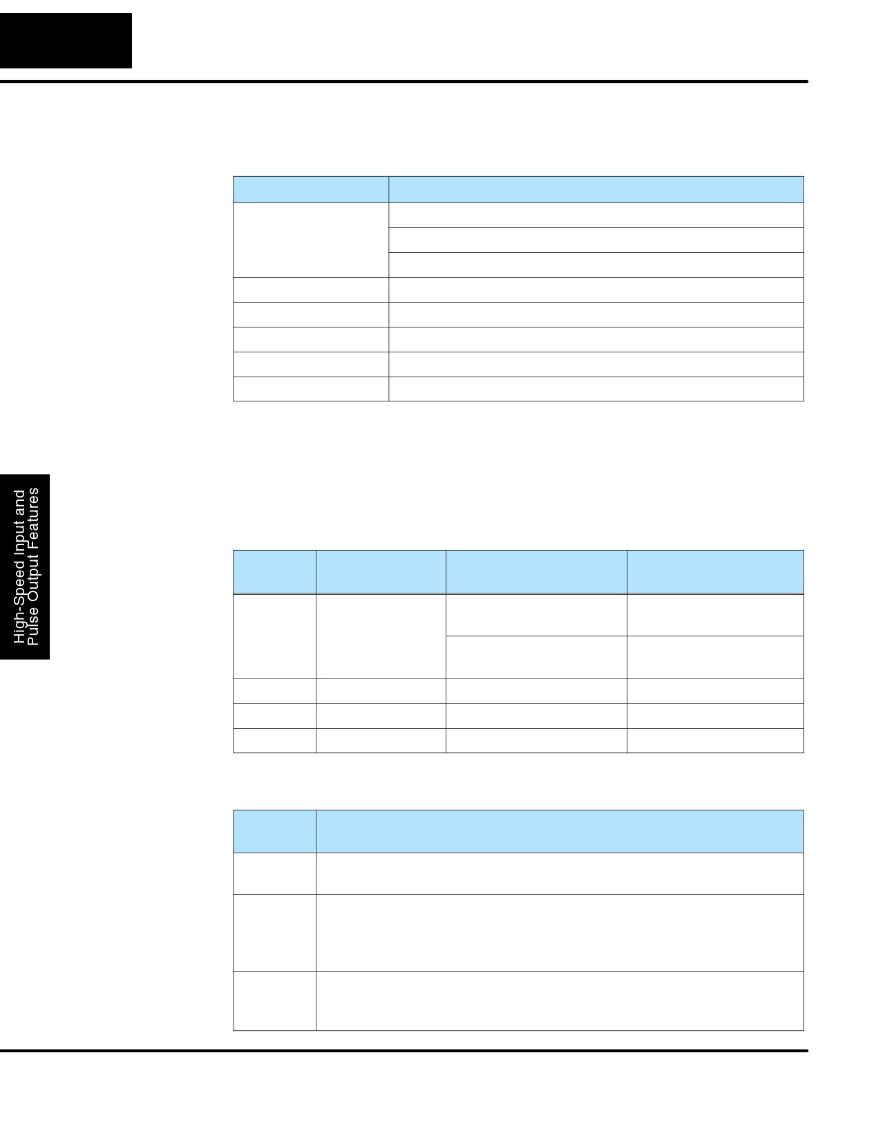
The motion control profiles generated in Pulse Output Mode have the following
Specifications
specifications:
Parameter
Specification
Profiles
Trapezoidal - Accel Slope / Target Velocity / Decel Slope
Registration - Velocity to Position Control on Interrupt
Velocity Control - Speed and Direction only
Position Range
-88388608 to 88388607
Positioning
Absolute / relative command
Velocity Range
40 Hz to 7 kHz
V-memory registers
V2320 to V2325 (Profile Parameter Table)
Current Position
CT76 and CT77 (V1076 and V1077)
Physical I/O
The configurable discrete I/O options for Pulse Output Mode are listed in the table
Configuration
below. Physical input X0 is not available, because the CPU uses logical X0 contact to
sense “profile complete”. Therefore, V7634 is put to another use: selecting
pulse/direction or CCW/CW modes for the pulse outputs. Inputs X1 and X3 can only
be filtered inputs. Input X2 is dedicated as the external interrupt for use in registration
mode.
Physical
Configuration
Function
Hex Code
Input
Register
Required
–
V7634
Y0 = Pulse
0103
Y1 = Direction
Y0 = CW Pulse
0003
Y1 = CCW Pulse
X1
V7635
Filtered Input
xx06 (xx = filter time)
X2
V7636
External Interrupt
1006
X3
V7637
Filtered Input
xx06 (xx = filter time)
Logical I/O
The following logical I/O references define functions that allow the HSIO
to
Functions
communicate with the ladder program.
Logical
Function
I/O
X0
Profile Complete - the HSIO turns on X0 to the CPU when the
profile completes. Goes back off when Start Profile (Y0) turns on.
Y0
Start Profile - the ladder program turns on Y0 to start motion. If
turned off before the move completes, motion stops. Turning it on
again will start another profile, unless the current position equals
the target position.
Y1
Preload Position Value - if motion is stopped and Start Profile is off,
you can load a new value in CT76/CT77, and turn on Y1. At that
transition, the value in CT76/CT77 becomes the current position.
DL105 PLC User Manual, 2nd Edition, Rev. A
3-27
High-Speed Input and Pulse Output Features
Setup for Mode 30
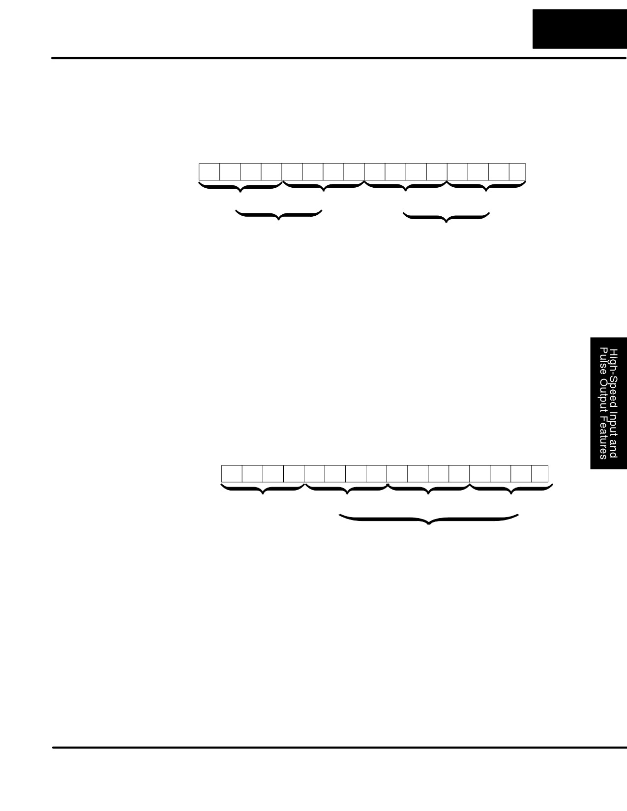
Recall that V7633 is the HSIO Mode Select register. Refer to the diagram below. Use
BCD 30 in the lower byte to select Pulse Output Mode. Use BCD 00 or 20 in the upper
byte as required. Combine the two bytes into a data word “xx30”, for writing to
V7633.
Memory Location V7633
Bits
15
14
13
12
11
10
9
8
7
6
5
4
3
2
1
0
0
0
1
0
0
0
0
0
0
0
1
1
0
0
0
0
2
0
3
0
Miscellaneous Setup (BCD)
HSIO Mode Setup (BCD)
00 = Power Up in Previous Mode
20 = Power Up in Run Mode Always
30 = Pulse Output
Choose the most convenient method of programming V7633 from the following:
S Include load and out instructions in your ladder program
S DirectSOFT32’s memory editor
S Use the Handheld Programmer D2-HPP
We recommend using the first method above so that the HSIO setup becomes an
integral part of your application program. An example program later in this section
shows how to to this.
Profile / Velocity
The first location in the Profile Parameter Table stores two key pieces of information.
Select Register
The upper four bits (12-15) select the type of profile required. The lower 12 bits
(0-11) select the Target Velocity.
Memory Location V2320 (default)
Bits
15
14
13
12
11
10
9
8
7
6
5
4
3
2
1
0
0
0
0
0
0
1
1
1
0
0
0
0
0
0
0
0
0
7
0
0
Profile Select (BCD)
Target Velocity Value
0 = Trapezoidal Profile, Absolute Position
Range = 4 to 700, representing
8 = Trapezoidal Profile, Relative Position
40 Hz to 7 kHz pulse rate
9 = Registration Profile, Relative Position
2 = Velocity Profile
The ladder program must program this location before initiating any of the three
profiles. The LD and OUT instruction will write all 16 bits, so be sure to fully specify
the full four-digit BCD value for the Position / Velocity Select Register each time.
The absolute and relative selection determines how the HSIO circuit will interpret
your specified target position. Absolute position targets are referenced to zero.
Relative position targets are referenced to the current position (previous target
position). You may choose whichever reference method that is most convenient for
your application.
DL105 PLC User Manual, 2nd Edition, Rev. A
3-28
High-speed Input and Pulse Output Features
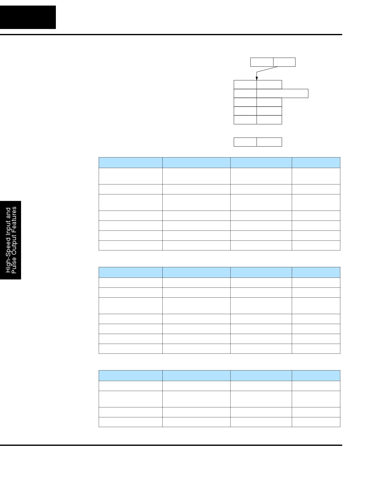
Profile
V7630 is a pointer location which points to
Profile Table Pointer
Parameter Table
the beginning of the Profile Parameter
V7630
2320
Table. The default starting location for the
profile parameter table is V2320.
Profile Parameter Table
However, you may change this by
V2320
xxxx
programming a different value in V7630.
V2321
xxxx
xxxx
Remember to use the LDA (load address)
V2323
xxxx
instruction, converting octal into hex.
V2324
xxxx
The HSIO uses the next V-memory
register past the bottom of the profile
V2325
xxxx
parameter table to indicate profile errors.
Pulse Output Error Code
See the error table at the end of this
section for error code definitions.
V2326
00xx
Trapezoidal Profile
V-Memory
Function
Range
Units
V2320, bits 12-15
Trapezoidal Profile
0=absolute,
-
8=relative
V2320, bits 0-11
Target Velocity Value
4 to 700
x 10 pps
V2321/ 2322
Target Position Value
-88388608 to
Pulses
88388607
V2323
Starting Velocity
4 to 100
x 10 pps
V2324
Acceleration Time
1 to 100
x 100 mS
V2325
Deceleration Time
1 to 100
x 100 mS
V2326
Error Code
(see end of section)
-
Registration Profile
V-Memory
Function
Range
Units
V2320, bits 12-15
Registration Profile
9=relative
-
V2320, bits 0-11
Target Velocity Value
4 to 700
x 10 pps
V2321/ 2322
Target Position Value
-88388608 to
Pulses
88388607
V2323
Starting Velocity
4 to 100
x 10 pps
V2324
Acceleration Time
1 to 100
x 100 mS
V2325
Deceleration Time
1 to 100
x 100 mS
V2326
Error Code
(see end of section)
-
Velocity Profile
V-Memory
Function
Range
Units
V2320
Velocity Profile
2000 only
-
V2321/ 2322
Direction Select
80000000=CCW,
Pulses
0=CW
V2323
Velocity
4 to 700
x 10 pps
V2326
Error Code
(see end of section)
-
DL105 PLC User Manual, 2nd Edition, Rev. A
3-29
High-Speed Input and Pulse Output Features
Choosing the
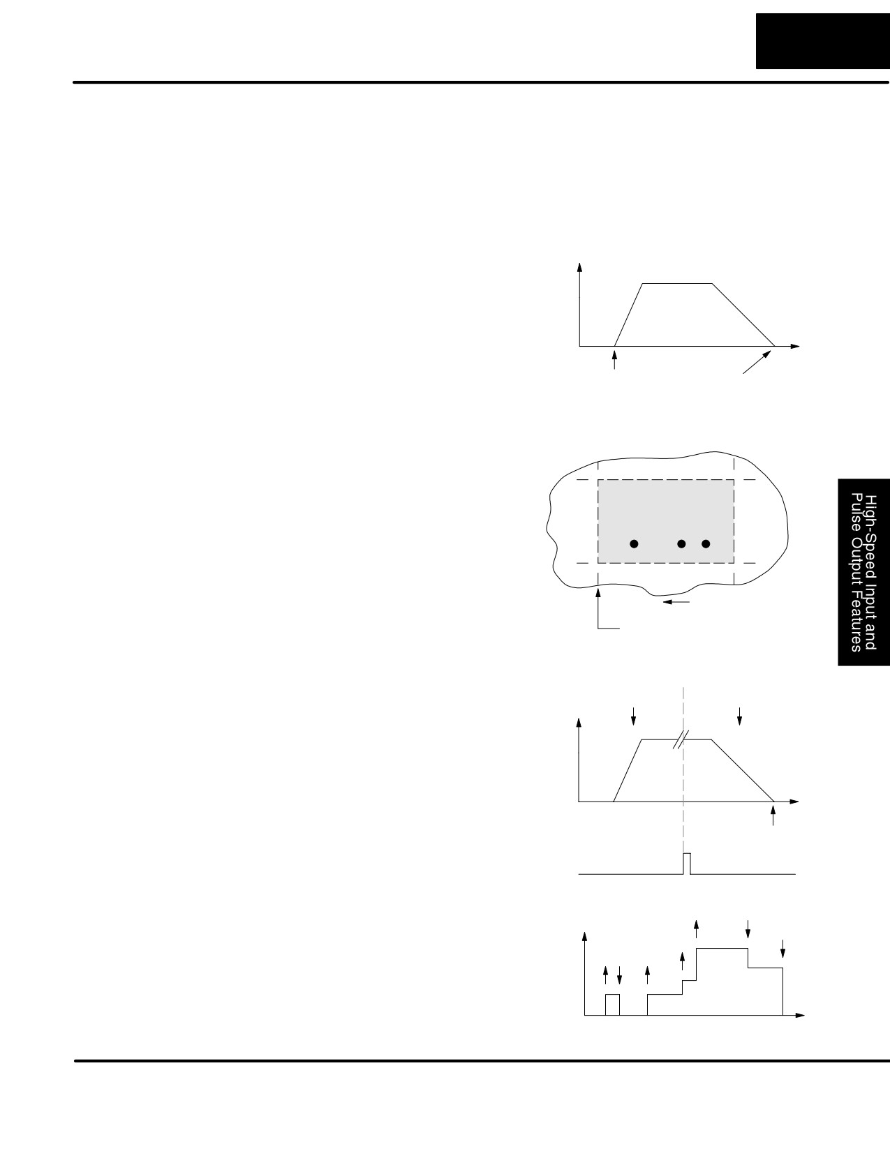
Pulse Output Mode generates three types of motion profiles. Most applications use
Profile Type
one type for most moves. However, each move can be different if required.
S Trapezoidal - Accel Slope to Target Velocity to Decel Slope
S Registration - Velocity to Position Control on Interrupt
S Velocity Control - Speed and Direction only
Trapezoidal
The trapezoidal profile is the most
Trapezoidal Profile
Profile Defined
common positioning profile. It moves the
Velocity
load to a pre-defined target position by
Fixed Velocity
creating a move profile. The acceleration
slope is applied at the starting position.
Accel
Decel
The deceleration slope is applied
backwards from the target position. The
remainder of the move in the middle is
Time
spent traveling at a defined velocity.
Start position Target position
Trapezoidal profiles are best for simple point-to-point moves, when the distance
between the starting and ending positions of the move is known in advance.
Registration and
Registration profiles solve a class of
Home Search
motion control problems. In some
Profiles Defined
applications, product material in work
moves past a work tool such as a drill
Scrap
Finished part area
station. Shown to the right, registration
Area
marks on the scrap area of the work-piece
allow a machine tool to register its position
relative to the rectangle, to drill properly.
Home search moves allow open-loop
direction of motion
motion systems to re-calibrate (preload)
Registration marks
the current position value at powerup.
Registration profiles are a combination of
Registration Profile
velocity and position control modes. The
Velocity
Position
move begins by accelerating to a
Control
Control
Velocity
programmed velocity. The velocity is
sustained and the move is of indefinite
duration. When an external interrupt
signal occurs
(due to registration
Accel
Decel
sensing), the profile switches from velocity
to position control. The move ends by
continuing motion a pre-defined distance
past the interrupt point (such as a drill hole
Target position
location). The deceleration ramp is
Interrupt
applied in advance of the target position.
Velocity Profile
The velocity profile controls only the
Velocity Profile
Velocity
Defined
direction and speed of motion. There is no
target position specified, so the move can
be of indefinite length. Only the first
velocity value needs to be defined. The
remaining velocity values can be created
while motion in in progress. Arrows in the
profile shown indicate velocity changes.
Time
DL105 PLC User Manual, 2nd Edition, Rev. A
3-30
High-speed Input and Pulse Output Features
Trapezoidal Profile Operation
The trapezoidal profile is best suited for simple point-to-point moves, when the target
Trapezoidal Profile
position is known in advance. Starting velocities must be within the rage of 40 pps to
Applications
1 kpps. The remainder of the profile parameters are in the profile parameter table.
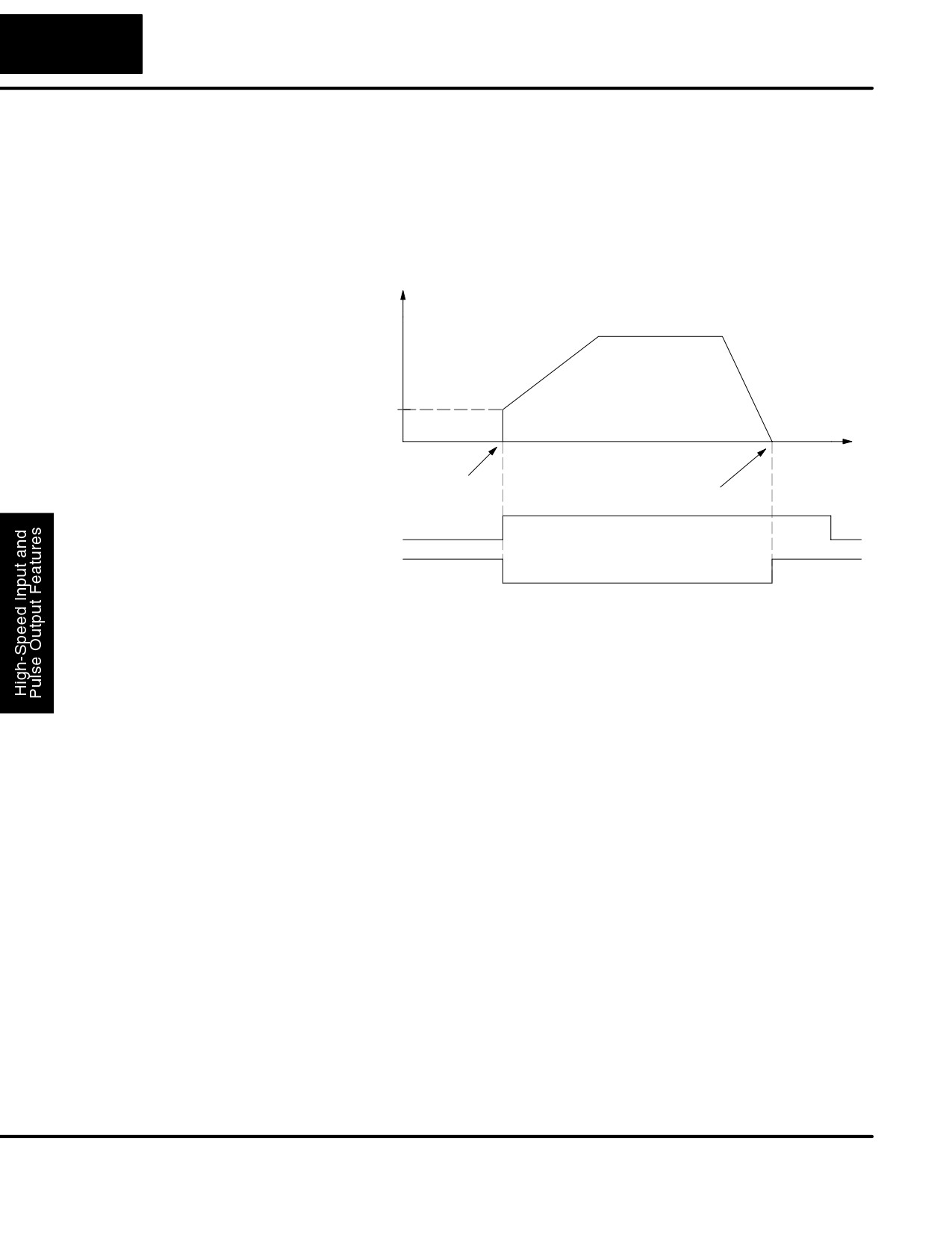
Trapezoidal Profile
Velocity
Target Velocity
Accel
Decel
Starting
Velocity
Time
Start position
Target position
Start
Y0
Profile
Complete
X0
The time line of signal traces below the profile indicates the order of events.
The HSIO uses logical output Y0 as the Start input to the HSIO, which starts the
profile. Immediately the HSIO turns off the Profile Complete signal (logical X0), so
the ladder program can monitor the progress of the move. Typically a ladder
program will monitor this bit so it knows when to initiate the next profile move.
If you are familiar with motion control, you’ll notice that we do not have to specify the
direction of the move. The HSIO function examines the target position relative to the
current position, and automatically outputs the correct direction information to the
motor drive.
Notice that the motion accelerates immediately to the starting velocity. This segment
is useful in stepper systems so we can jump past low speed areas when low-torque
problems or a resonant point in the motor might cause a stall. (When a stepper motor
stalls, we have lost the position of the load in open-loop positioning systems).
However, is is preferable not to make the starting velocity too large, because the
stepper motor will also “slip” some pulses due to the inertia of the system.
When you need to change the current position value, use logical Y1 output coil to
load a new value into the HSIO counter. If the ladder program loads a new value in
CT76/CT77 (V1076/V1077), then energizing Y1 will copy that value into the HSIO
circuit counter. This must occur before the profile begins, because the HSIO ignores
Y1 during motion.
DL105 PLC User Manual, 2nd Edition, Rev. A
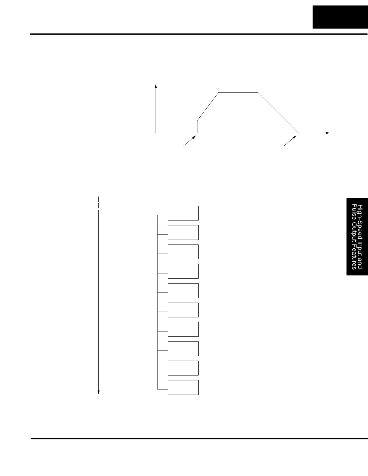
3-31
High-Speed Input and Pulse Output Features
Trapezoidal Profile
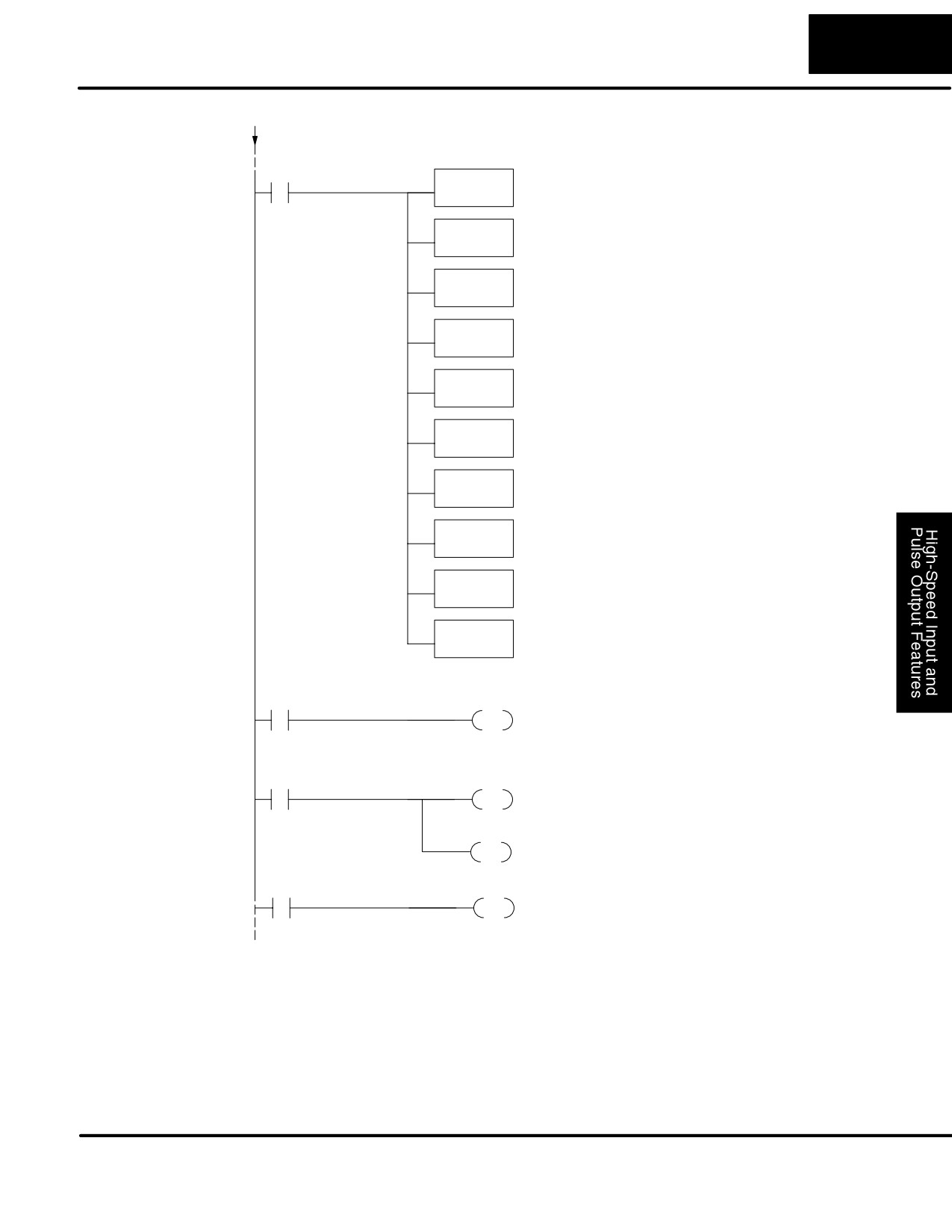
The trapezoidal profile we want to perform is drawn and labeled in the following
Program Example
figure. It consists of a non-zero starting velocity, and moderate target velocity.
Trapezoidal Profile
Velocity
Target Velocity = 1 kHz
Accel = 2 sec
Decel = 4 sec
Starting
Velocity = 40
Time
Start position
Target position = 5000
The following program will realize the profile drawn above, when executed. The
beginning of the program contains all the necessary setup parameters for Pulse
Output Mode 30. We only have to do this once in the program, so we use first-scan
contact SP0 to trigger the setup.
DirectSOFT32
SP0
Load constant K30 into the accumulator. This selects
LD
Mode 30 as the HSIO mode.
K30
Mode 30
Output the constant to V7633, the location of the HSIO
OUT
Mode select register.
V7633
Load the octal address of the beginning of the Profile
Locate Parameter
LDA
Parameter Table. The LDA instruction converts this to a
O2320
Table (optional)
hex number in the accumulator.
Output this address to V7630, the location of the pointer
OUT
to the Profile Parameter Table.
V7630
Load the constant K103 which is required to select
Select Pulse /
LD
pulse and direction for physical Y0 and Y1 functions,
K103
respectively (use K3 if your application needs CCW
Direction
and CW).
OUT
Output this constant to V7634, configuring the pulse
V7634
output type.
Filtered Inputs
LD
Load the constant K1006 which is required to select
filtered inputs with a 10 mS filter time constant.
K1006
OUT
Output this constant to V7635, configuring X1.
V7635
OUT
Output this constant to V7636, configuring X2.
V7636
OUT
Output this constant to V7637, configuring X3.
V7637
DL105 PLC User Manual, 2nd Edition, Rev. A
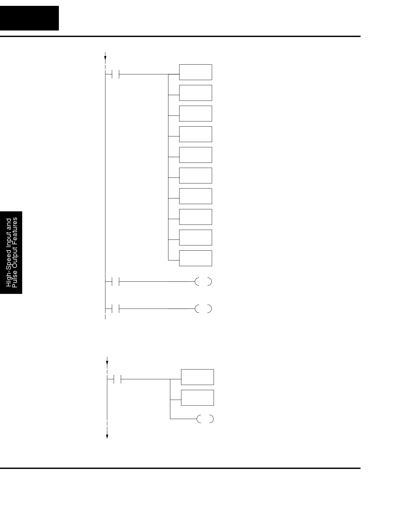
3-32
High-speed Input and Pulse Output Features
Program
Example Cont’d
SP0
Load the constant K100 which is required to select
LD
Trapzoidal Profile, absolute positioning, and a target
K100
velocity of 1 kHz.
Profile / Target
Output this constant to V2320, the location of the Profile
OUT
Select / Starting Velocity setup register.
Velocity
V2320
Load the constant K5000 which selects a target
Target Position
LDD
position of 5000 pulses. Don’t forget to use double
K5000
word size (8-digit BCD position value).
Output this constant to V2321 and V2322, the location of
OUTD
the Target Position double-word register.
V2321
Load the constant K4 which is required to select a
Starting Velocity
LD
starting velocity of 40 Hz (4 x 10 pps).
K4
Output this constant to V2323, the location of the starting
OUT
velocity parameter register.
V2323
Load the constant K20 which is required to select an
Acceleration
LD
acceleration time of 2 seconds (20 x 100 mS).
K20
Output this constant to V2324, the location of the
OUT
acceleration parameter register.
V2324
Load the constant K40 which is required to select a
Deceleration
LD
deceleration time of 4 seconds (40 x 100 mS).
K40
Output this constant to V2325, the location of the
OUT
deceleration parameter register.
V2325
Start Profile
X3
Y0
We use a spare filtered input to allow the operator
OUT
to start the profile. When the operator turns X3 ON,
then OFF, logical output Y0 starts the profile.
Profile Complete
X0
Y2
X0 is the logical output of the HSIO to indicate the
OUT
move is complete. We use Y2 to energize an
annunciator that the profile has finished.
Preload
At any time you can write (preload) a new position into the current position value.
Position Value
This often done after a home search (see the registration example programs).
SP0
Load the constant K1000 as the new current position
LDD
value.
K1000
Profile / Target
Output this constant to V1076/V1077 (CTA76/CTA77). the
OUTD
location of the current position value.
Velocity
V1076
Y1
PD Turn on Y1 for 1 scan. The off-to-on transition
causes the HSIO to preload the current position
with the value in
DL105 PLC User Manual, 2nd Edition, Rev. A
3-33
High-Speed Input and Pulse Output Features
Registration Profile Operation
Registration
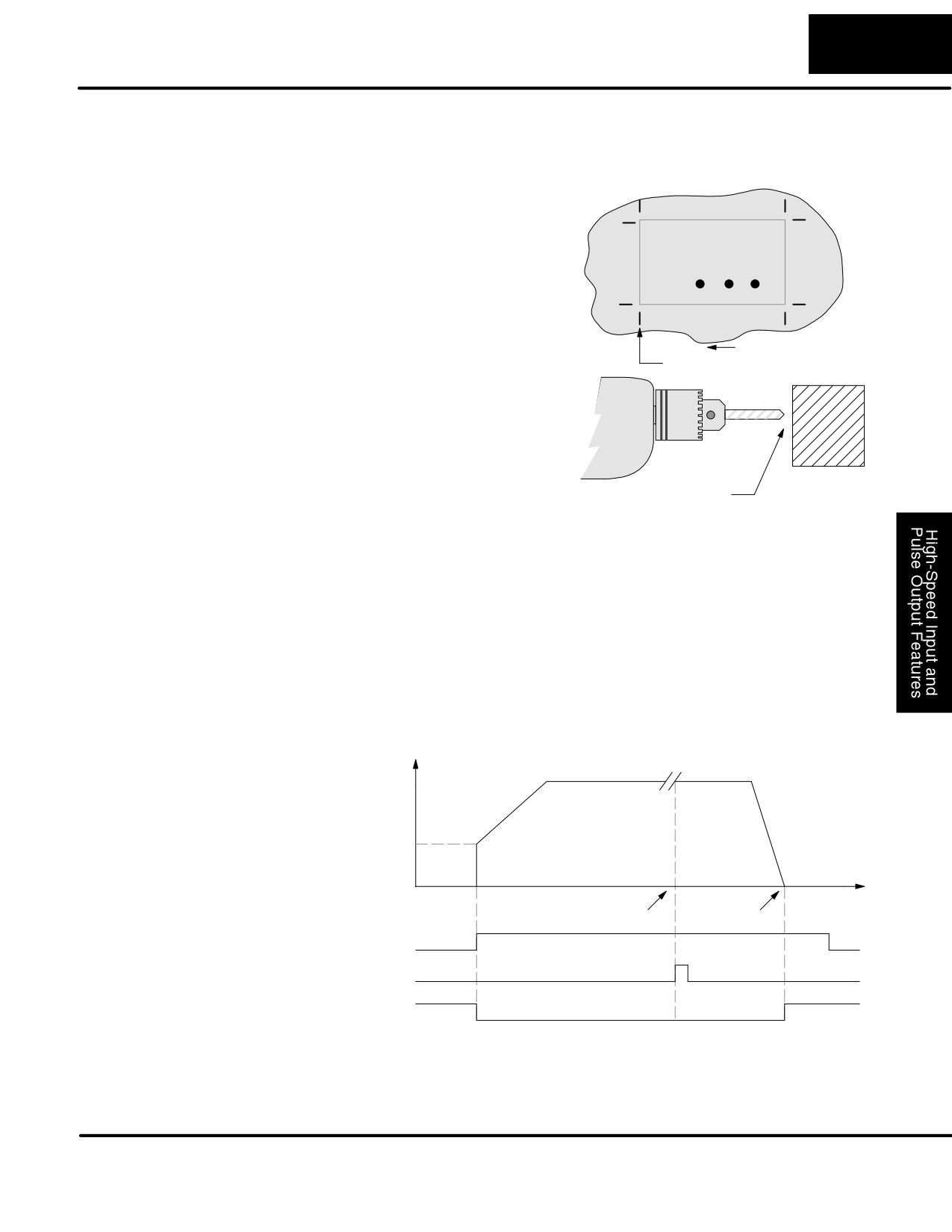
1. In a typical application shown to the
Applications
right, product material in work moves past
a work tool such as a drill. Registration
Scrap
marks on the scrap area of the work-piece
Finished part area
Area
allow a machine tool to register its position
relative to the rectangle, to drill properly.
2. In other examples of registration, the
work piece is stationary and the tool
direction of motion
moves. A drill bit may approach the
Registration marks
surface of a part in work, preparing to drill
a hole of precise depth. However, the drill
bit length gradually decreases due to tool
wear. A method to overcome this is to
detect the moment of contact with the part
surface on each drill, moving the bit into
the part a constant distance after contact.
Detect contact
3. The home search move allows a motion system to calibrate its position on
startup. In this case, the positioning system makes an indefinite move and waits for
the load to pass by a home limit switch. This creates an interrupt at the moment when
the load is in a known position. We then stop motion and preload the position value
with a number which equates to the physical “home position”.
The registration profile begins with only velocity control. When an interrupt pulse
occurs on physical input X2, the starting position is declared to be the present count
(current load position). The velocity control switches to position control, moving the
load to the target position. Note that the minimum starting velocity is 40 pps. This
instantaneous velocity accommodates stepper motors that can stall at low speeds.
Registration Profile
Velocity
Target Velocity
Accel
Decel
Starting
Velocity
Start
Target
Time
position
position
Start
Y0
External Interrupt X2
Profile Complete X0
The time line of signal traces below the profile indicates the order of events. The
CPU uses logical output Y0 to start the profile. Immediately the HSIO turns off the
Profile Complete signal (logical X0), so the ladder program can monitor the move’s
completion by sensing the signal’s on state.
DL105 PLC User Manual, 2nd Edition, Rev. A
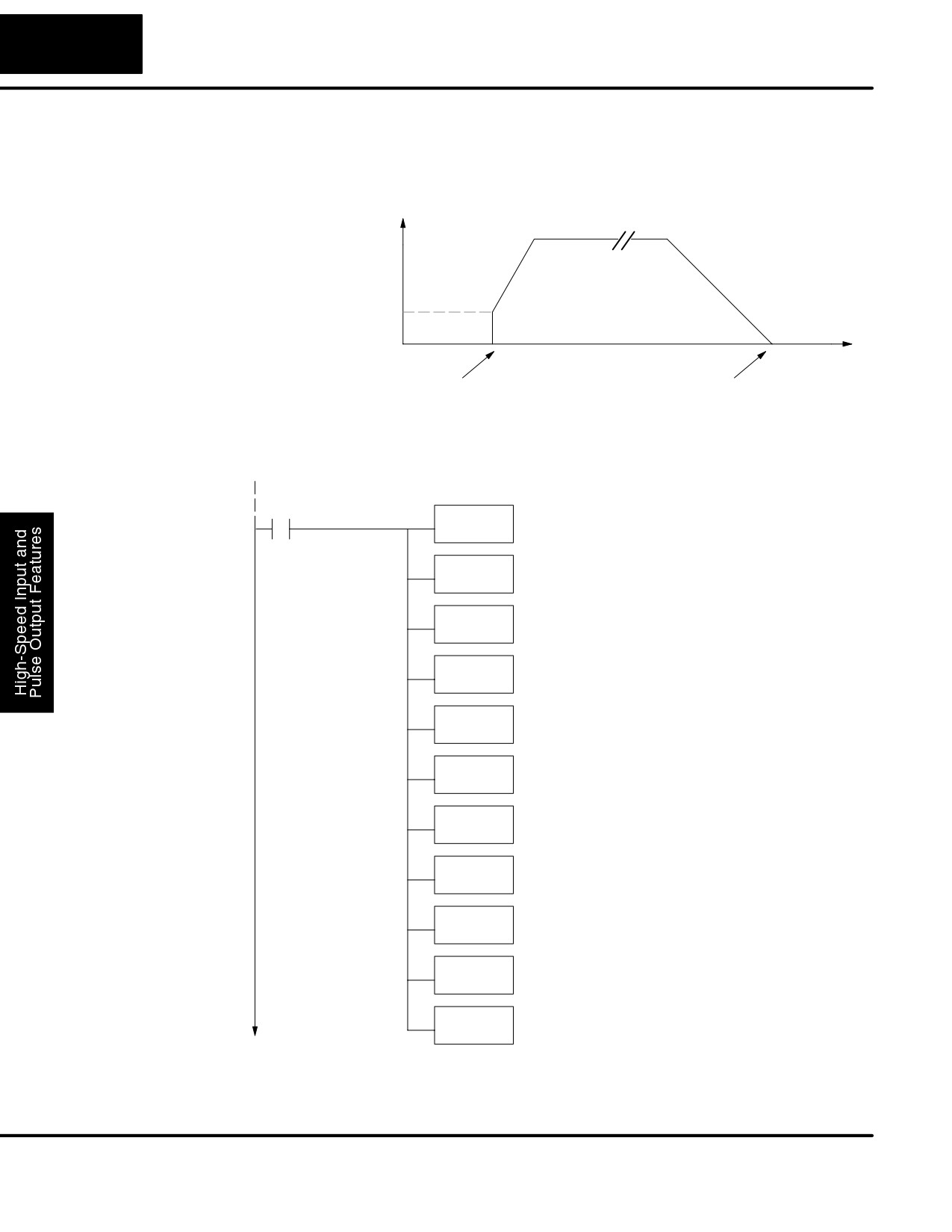
3-34
High-speed Input and Pulse Output Features
Registration Profile
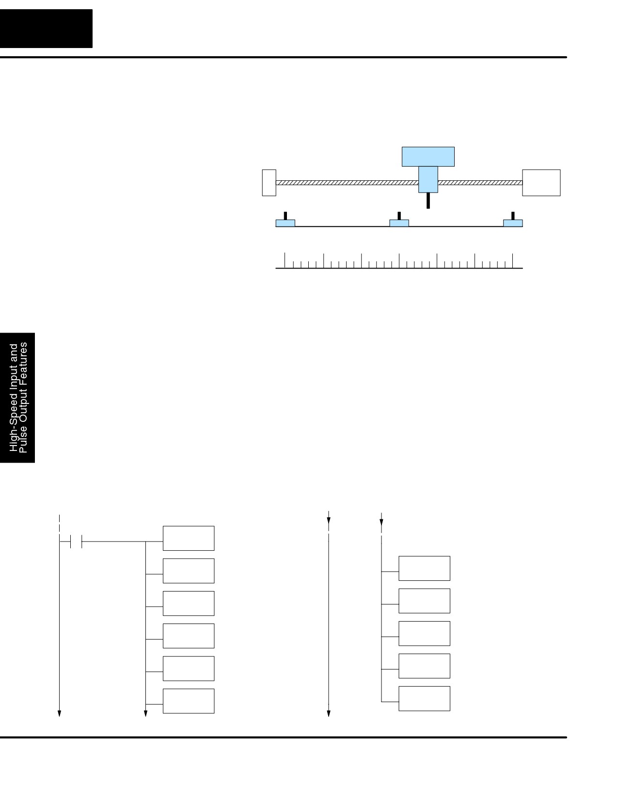
The registration profile we want to perform is drawn and labeled in the following
Program Example
figure. It consists of a non-zero starting velocity, and moderate target velocity.
Registration Profile
Velocity
Target Velocity = 1 kHz
Accel = 2 sec
Decel = 4 sec
Starting
Velocity = 40
Time
Start position
Target position = 5000
The following program will realize the profile drawn above, when executed. The first
program rung contains all the necessary setup parameters. We only have to do this
once in the program, so we use first-scan contact SP0 to trigger the setup.
DirectSOFT32
SP0
Load constant K30 into the accumulator. This selects
LD
Mode 30 as the HSIO mode.
K30
Mode 30
Output this constant to V7633, the location of the HSIO
OUT
Mode select register.
V7633
Load the octal address of the beginning of the Profile
Locate Parameter
LDA
Parameter Table. The LDA instruction converts this to a
Table (optional)
O2320
hex number in the accumulator.
Output this address to V7630, the location of the pointer
OUT
to the Profile Parameter Table.
V7630
Load the constant K103 which is required to select
Select Pulse /
LD
pulse and direction for physical Y0 and Y1 functions,
K103
Direction
respectively (your application may use CCW and CW).
Output this constant to V7634, configuring the pulse
OUT
output type.
V7634
Load the constant K2006 which is required to select
Filtered Inputs
LD
filtered inputs with a 20 mS filter time constant.
K2006
Output this constant to V7635, configuring X1.
OUT
V7635
Output this constant to V7637, configuring X3.
OUT
V7637
Load the constant K1006 which is required to select the
LD
external interrupt.
K1006
Output this constant to V7636, configuring X2, the
OUT
registration interrupt input.
V7636
DL105 PLC User Manual, 2nd Edition, Rev. A
3-35
High-Speed Input and Pulse Output Features
Program
Example Cont’d
SP0
Load the constant K9100 which is required to select
LD
Registration Profile, relative positioning, and a target
K9100
velocity of 1 kHz (9xxx times 10 pps).
Profile / Target
Output this constant to V2320, the location of the Profile
OUT
Select / Starting Velocity setup register.
Velocity
V2320
Load the constant K5000 which selects a target
Target Position
LDD
position of 5000 pulses. Don’t forget to use double
K5000
word size (8-digit BCD position value).
Output this constant to V2321 and V2322, the location of
OUTD
the Target Position double-word register.
V2321
Load the constant K4 which is required to select a
Starting Velocity
LD
starting velocity of 40 Hz (4 x 10 pps).
K4
Output this constant to V2323, the location of the starting
OUT
velocity parameter register.
V2323
Load the constant K20 which is required to select an
Acceleration
LD
acceleration time of 2 seconds (20 x 100 mS).
K20
Output this constant to V2324, the location of the
OUT
acceleration parameter register.
V2324
Load the constant K40 which is required to select a
Deceleration
LD
deceleration time of 4 seconds (40 x 100 mS).
K40
Output this constant to V2325, the location of the
OUT
deceleration parameter register.
V2325
Start Profile
X3
Y0
SET
We use a spare filtered input to allow the operator
to start the profile. X3 is a momentary Start switch.
When the operator turns X3 ON, logical output Y0
Profile Complete
starts the profile.
X0
Y2
OUT
X0 is the logical output of the HSIO to indicate the
move is complete. We use Y2 to energize an
annunciator that the profile has finished. This won’t
C0
occur until after the interrupt from X2 has occurred
PD
and the profile is complete.
C0
Y0
RST
The profile will begin when the start input (X3) is given. Then the motion begins an
indefinite move, which lasts until an external interrupt on X2 occurs. Then the motion
continues on for 5000 more pulses before stopping.
DL105 PLC User Manual, 2nd Edition, Rev. A
3-36
High-speed Input and Pulse Output Features
One of the more challenging aspects of motion control is the establishment of actual
Home Search
position at powerup. This is especially true for open-loop systems which do not have
Program Example
a position feedback device. However, a simple limit switch located at an exact
location on the positioning mechanism can provide “position feedback” at one point.
For most stepper control systems, this method is a good and economical solution.
Load
Positioning System
Motor
Limit Switches
CCW limit (X1)
Home limit (X2)
CW limit (X3)
Motion
Numbering System
-3000
-2000
-1000
0
1000
2000
3000
In the drawing above, the load moves left or right depending on the CCW/CW
direction of motor rotation. The PLC ladder program senses the CCW and CW limit
switches to stop the motor, before the load moves out-of-bounds and damages the
machine. The home limit switch is used at powerup to establish the actual position.
The numbering system is arbitrary, depending on a machine’s engineering units.
At powerup, we do not know whether the load is located to the left or to the right of the
home limit switch. Therefore, we will initiate a home search profile, using the
registration mode. The home limit switch is wired to X2, causing the interrupt. We
choose an arbitrary initial search direction, moving in the CW (left-to-right) direction.
S If the home limit switch closes first, then we stop and initialize the
position (this value is typically “0”, but it may be different if preferred).
S However, if the CW limit switch closes first, we must reverse the motor
and move until the home limit switch closes, stopping just past it.
In the latter case, we repeat the first move, because we always need to make the
final approach to the home limit switch from the same direction, so that the final
physical position is the same in either case!
DirectSOFT32
SP0
Selects Mode 30 as
LD
the HSIO mode.
K30
Filtered Inputs
The constant K2006
Mode 30
LD
OUT
selects a 20 mS filter
K2006
V7633
time constant.
Output this constant to
Locate
Configure the address
OUT
LDA
V7635, configuring X1.
Parameter
O2320
of the parameter table.
V7635
Table (optional)
Output this constant to
OUT
OUT
V7637, configuring X3.
V7630
V7637
The constant K1006
Select Pulse /
Configure the Y0 and Y1
LD
LD
selects a 10 mS filter
pulse outputs for pulse
Direction
K1006
K103
time constant.
and direction, respectively.
Output this constant to
OUT
OUT
V7636, configuring X2, the
V7636
V7634
registration interrupt input.
DL105 PLC User Manual, 2nd Edition, Rev. A
3-37
High-Speed Input and Pulse Output Features
Profile / Target Velocity
C1
SP0
Add a timer to
Select Registration Profile,
TMR
LD
create a slight
relative positioning, and a
T0
K9100
delay before
target velocity of 1000 pps
K5
reversing motor.
(9xxx times 10 pps).
OUT
T0
C2
V2320
SET
CCW delay done.
Starting Velocity
The constant K4 selects a
LD
Y0
starting velocity of 40 Hz
K4
(4 x 10 pps).
SET Start profile again.
CCW past home
OUT
C2
C3
X2
C3
V2323
SET
CCW past home
The constant K20 selects
Acceleration
LD
an acceleration time of 2
Load a small
K20
LDD
seconds (20 x 100 mS).
positive position
K50
count (go CW).
OUT
V2324
OUTD
V2321
Deceleration
We’ll choose the same for
OUT
the deceleration value.
Home Limit found, CW search direction
V2325
C3
X2
Y0
X10
C10
Start the home search
RST
Turn off Start Profile.
SET
when X10 turns on.
C4
Search in CW direction
SETGo CW back to
home.
C10
C0
The constant K50 selects
C4
LDD
TMR
Add a timer to
a target position of 50
create a slight
K50
pulses (CW direction).
T1
delay before
K5
reversing motor.
Target Position
OUTD
V2321
T1
C5
Turn on Start Profile,
SET CW delay done.
Y0
searching for either the
home limit or the CW limit
SET
Y0
(depends on our starting
position).
SET Start profile again.
C0
Set C0 to indicate the CW
SET
Home Limit found, CW search direction
home search has begun.
CW Limit found
C0
C1 C3
X2
Y0
C0
C1
X3
Y0
RST Turn off Start Profile.
RST
Turn off Start Profile.
C5
Load the constant
LDD
The constant -K200
K0 for our initialized
K0
LDD
selects a target
position.
K80000200
position of -200
pulses, which is in
OUTD
Output this constant
the CCW direction.
V1076
to C1076/V1077.
OUTD
V2321
C1
The CW limit has
SET
been reached.
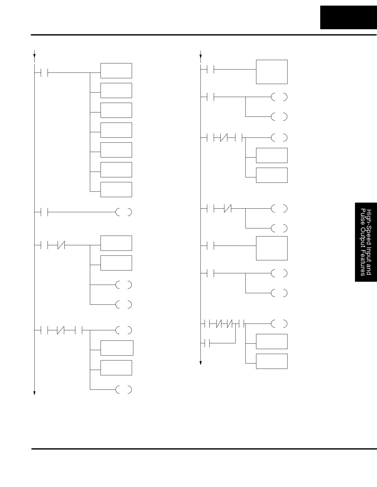
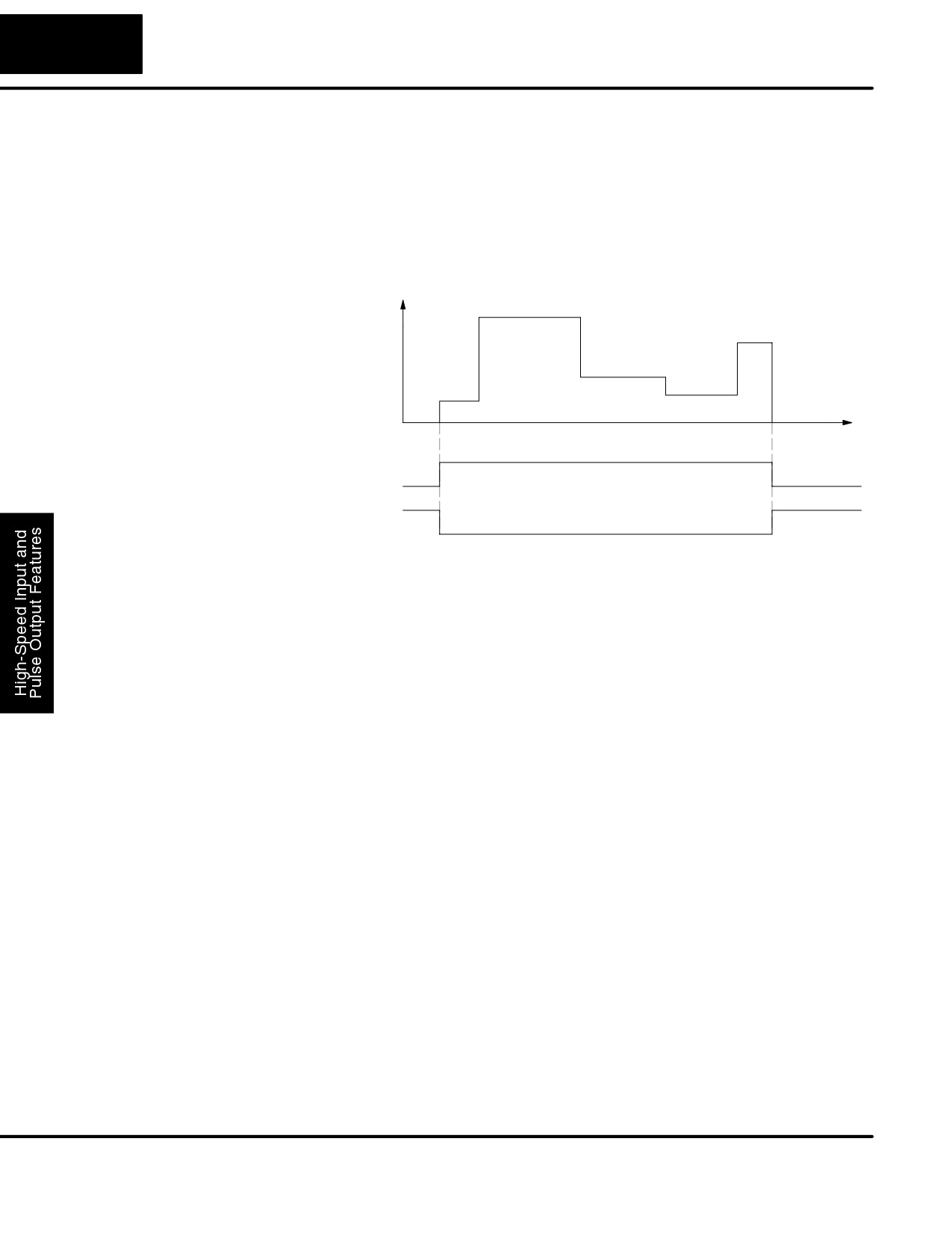
The home search profile will execute specific parts of the program, based on the
order of detection of the limit switches. Ladder logic sets C0 to initiate a home search
in the CW direction. If the CW limit is encountered, the program searches for home in
the CCW direction, passes it slightly, and does the final CW search for home. After
reaching home, the last ladder rung preloads the current position to “0”.
DL105 PLC User Manual, 2nd Edition, Rev. A
3-38
High-speed Input and Pulse Output Features
Velocity Profile Operation
Velocity Profile
The velocity profile is best suited for applications which involve motion but do not
Applications
require moves to specific points. Conveyor speed control is a typical example.
Velocity Profile
Velocity
Time
Start
Y0
Profile
Complete X0
The time line of signal traces below the profile indicates the order of events.
Assuming the velocity is set greater than zero, motion begins when the Start input
(Y0) energizes. Since there is no end position target, the profile is considered in
progress as long as the Start input remains active. The profile complete logical input
to ladder logic (X0) correlates directly to the Start input status when velocity profiles
are in use.
While the Start input is active, the ladder program can command a velocity change
by writing a new value to the velocity register (V2323 by default). The full speed
range of 40 Hz to 7 kHz is available. Notice from the drawing that there are no
acceleration or deceleration ramps between velocity updates. This is how velocity
profiling works with the HSIO. However, the ladder program can command more
gradual velocity changes by incrementing or decrementing the velocity value more
slowly. A counter or timer can be useful in creating your own
acceleration/deceleration ramps. Unless the load must do a very complex move, it is
easier to let the HSIO function generate the accel/decel ramps by selecting the
trapezoidal or registration profiles instead.
Unlike the trapezoidal and registration profiles, you must specify the desired
direction of travel with velocity profiles. Load the direction select register
(V2321/V2322 by default) with 8000 0000 hex for CCW direction, or 0 for CW
direction.
DL105 PLC User Manual, 2nd Edition, Rev. A
3-39
High-Speed Input and Pulse Output Features
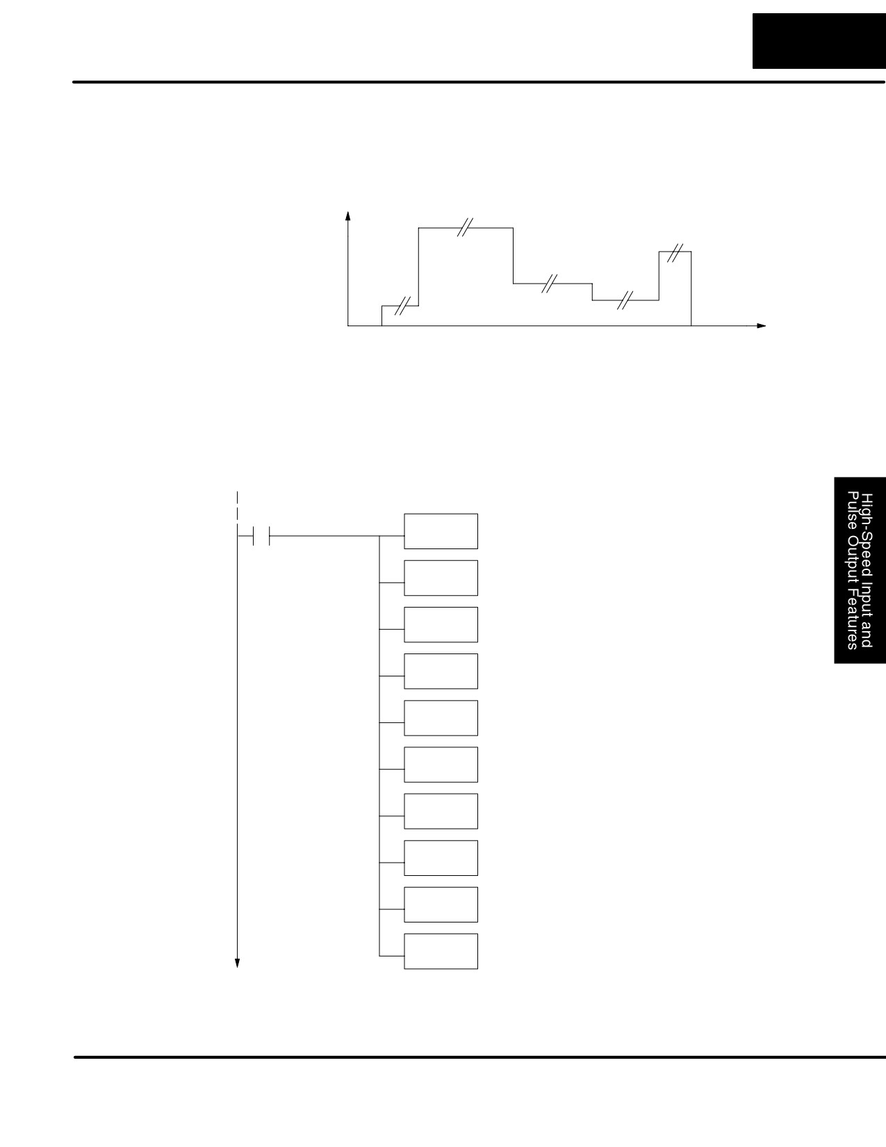
The velocity profile we want to perform is drawn and labeled in the following figure.
Velocity Profile
Each velocity segment is of indefinite length. The velocity only changes when ladder
Program Example
logic (or other device writing to V-memory) updates the velocity parameter.
Velocity Profile
Velocity
Time
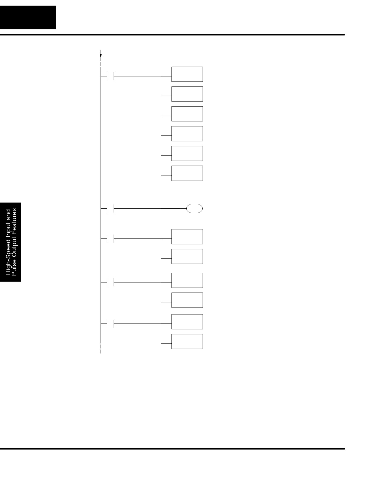
The following program uses dedicated discrete inputs to load in new velocity values.
This is a fun program to try, because you can create an infinite variety of profiles with
just two or three input switches. The intent is to turn on only one of X1, X2, or X3 at a
time. The beginning of the program contains all the necessary setup parameters for
Pulse Output Mode 30. We only have to do this once in the program, so we use
first-scan contact SP0 to trigger the setup.
DirectSOFT32
SP0
Load constant K30 into the accumulator. This selects
LD
Mode 30 as the HSIO mode.
K30
Mode 30
Output this constant to V7633, the location of the HSIO
OUT
Mode select register.
V7633
Load the octal address of the beginning of the Profile
Locate Parameter
LDA
Parameter Table. The LDA instruction converts this to
O2320
Table (optional)
hex number in the accumulator.
Output this address to V7630, the location of the pointer
OUT
to the Profile Parameter Table.
V7630
Load the constant K103 which is required to select
Select Pulse /
LD
pulse and direction for physical Y0 and Y1 functions,
K103
Direction
respectively (your application may use CCW and CW).
Output this constant to V7634, configuring the pulse
OUT
output type.
V7634
Load the constant K1006 which is required to select
Filtered Inputs
LD
filtered inputs with a 10 mS filter time constant.
K1006
Output this constant to V7635, configuring X1.
OUT
V7635
Output this constant to V7636, configuring X2.
OUT
V7636
Output this constant to V7637, configuring X3.
OUT
V7637
DL105 PLC User Manual, 2nd Edition, Rev. A
3-40
High-speed Input and Pulse Output Features
Program
Example Cont’d
SP0
Load the constant K2000 which is required to select
LD
Velocity Profile. This data word contains no velocity
K2000
information in the case of velocity mode.
Profile / Target
Output this constant to V2320, the location of the Profile
OUT
Select setup register.
Velocity
V2320
Load the constant K80000000 which selects CCW
Select Direction
LDD
direction for Velocity Profiles. Don’t forget to use double
K80000000
word size (8-digit BCD position value).
Output this constant to V2321 and V2322, the location of
OUTD
the Target Position double-word register.
V2321
Load the constant K10 which is required to select an
Set Velocity
LD
initial velocity of 100 pps (uses x10 multiplier).
K10
Output this constant to V2323, the location of the velocity
OUT
parameter register. After the program is running, we can
V2323
write here again, using discrete input switches.
Start Profile
X1
Y0
OUT
We use a spare filtered input to allow the operator
to start the profile. When the operator turns X1 ON
and leaves it on, logical output Y0 starts the profile.
Go Slow
X2
Load the constant K50 which is required to select a
LD
velocity of 500 pps when the operator closes X2.
K50
Output this constant to V2323, the location of the velocity
OUT
parameter register. The speed will change immediately.
V2323
Go Moderately
X3
Load the constant K200 which is required to select a
LD
velocity of 2000 pps when the operator closes X3.
K200
Output this constant to V2323, the location of the velocity
OUT
parameter register. The speed will change immediately.
V2323
Go Fast
X4
Load the constant K600 which is required to select a
LD
velocity of 6000 pps when the operator closes X4.
K600
Output this constant to V2323, the location of the velocity
OUT
V2323
parameter register. The speed will change immediately.
DL105 PLC User Manual, 2nd Edition, Rev. A
3-41
High-Speed Input and Pulse Output Features
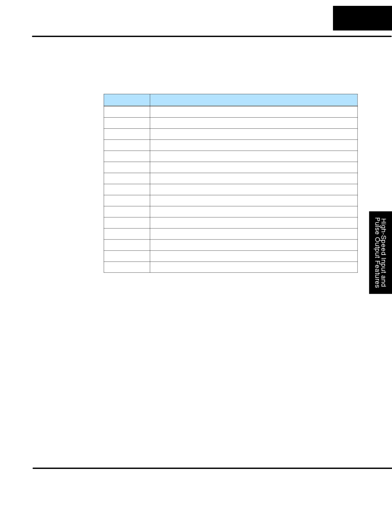
Pulse Output Error
The Profile Parameter Table starting at V2320 (default location) defines the profile.
Codes
Certain numbers will result in a error when the HSIO attempts to use the parameters
to execute a move profile. When an error occurs, the HSIO writes an error code in
V2326.
Error Code
Error Description
0000
No error
0010
Requested profile type code is invalid (must use 0, 1, 2, 8, or 9)
0020
Target Velocity is not in BCD
0021
Target Velocity is specified to be less than 40 pps
0022
Target Velocity is specified to be greater than 7,000 pps
0030
Target Position value is not in BCD
0040
Starting Velocity is not in BCD
0041
Starting Velocity is specified to be less than 40 pps
0042
Starting Velocity is specified to be greater than 1,000 pps
0050
Acceleration Time is not in BCD
0051
Acceleration Time is zero
0052
Acceleration Time is greater than 10 seconds
0010
Deceleration Time is not in BCD
0010
Deceleration Time is zero
0010
Deceleration Time is greater than 10 seconds
Most errors can be corrected by rechecking the Profile Parameter Table values. The
error is automatically cleared at powerup and at Program-to-Run Mode transitions.
Troubleshooting
If you’re having trouble with Mode 30 operation, please study the following
Guide for Mode 30
symptoms and possible causes. The most common problems are listed below:
Symptom: The stepper motor does not rotate.
Possible causes:
1. Configuration - Verify that the HSIO actually generates pulses on outputs
Y0 and Y1. Watch the status LEDs for Y0 and Y1 when you start a motion
profile. If the LEDs flicker on and off or are steadily on, the configuration is
probably correct.
2. Programming error - If there are no pulses on Y0 or Y1 you may have a
programming error. Check the contents of V2326 for an error code that may
be generated when the PLC attempts to do the move profile. Error code
descriptions are given above.
DL105 PLC User Manual, 2nd Edition, Rev. A
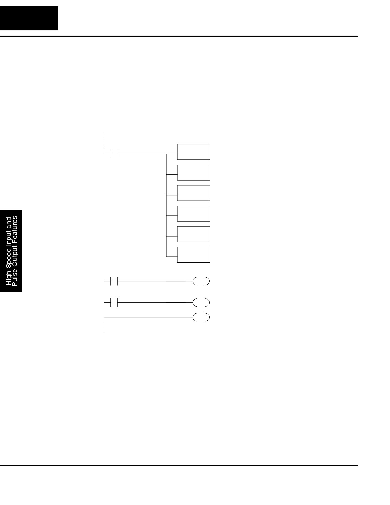
3-42
High-speed Input and Pulse Output Features
3. Wiring - Verify the wiring to the stepper motor is correct. Remember the
signal ground connection from the PLC to the motion system is required.
4. Motion system - Verify that the drive is powered and enabled. To verify the
motion system is working, you can use Mode 60 operation (normal PLC
inputs/outputs) as shown in the test program below. With it, you can
manually control Y0 and Y1 with X0 and X1, respectively. Using an input
simulator is ideal for this type of manual debugging. With the switches you
can single-step the motor in either direction. If the motor will not move with
this simple control, Mode 30 operation will not be possible until the problem
with the motor drive system or wiring is corrected.
DirectSOFT32
SP0
Load constant K60 into the accumulator. This
LD
selects Mode 60 as the HSIO mode.
K60
Mode 60
Output the constant to V7633, the location of the
OUT
HSIO Mode select register.
V7633
Load the constant K1006 which is required to configure
Filtered Inputs
LD
filtered inputs with a time constant of 10 mS.
K1006
Output this constant to V7634, configuring X0.
OUT
V7634
Output this constant to V7635, configuring X1.
OUT
V7635
Output this constant to V7636, configuring X2.
OUT
V7636
X0
Y0
OUT
Use a switch on X0 input to manually control output Y0.
X1
Y1
OUT
Use a switch on X1 input to manually control output Y1.
END
END coil marks the end of the main program..
5. Memory Error - HSIO configuration parameters are stored in the CPU
system memory. Corrupted data in this memory area can sometimes
interfere with proper HSIO operation. If all other corrective actions fail,
initializing the scratchpad memory may solve the problem. With
DirectSOFT32, select the PLC menu, then Setup, then Initialize
Scratchpad.
Symptom: The motor turns in the wrong direction.
Possible causes:
1. Wiring - If you have selected CW and CCW type operation, just swap the
wires on Y0 and Y1 outputs.
2. Direction control - If you have selected Pulse and Direction type
operation, just change the direction bit to the opposite state.
DL105 PLC User Manual, 2nd Edition, Rev. A
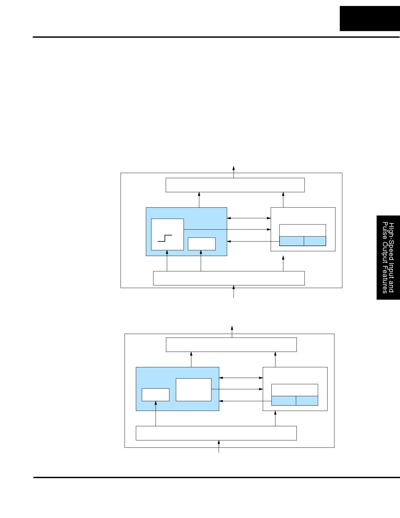
3-43
High-Speed Input and Pulse Output Features
Mode 40: High-Speed Interrupts
Purpose
The HSIO Mode 40 provides a high-speed interrupt to the ladder program. This
capability is provided for your choice of the following application scenarios:
S An external event needs to trigger an interrupt subroutine in the CPU.
Using immediate I/O instructions in the subroutine is typical.
S An interrupt routine needs to occur on a timed basis which is different
from the CPU scan time (either faster or slower). The timed interrupt is
programmable, from 5 to 999 mS.
Functional Block
The HSIO circuit creates the high-speed interrupt to the CPU. The following diagram
Diagram
shows the external interrupt option, which uses X0. In this configuration, X1, X2, and
X3 are all normal filtered inputs.
DL105
Output Circuit
PLC
Y0, Y1
Y2 - Y7
HSIO
I/O data
CPU
Interrupt
Interrupt
VĆmemory
Mode Select
V7633
xx40
FILTER
X0
X1, X2, X3
X4- X11
Input Circuit
Alternately, you may configure the HSIO circuit to generate interrupts based on a
timer, as shown below. In this configuration, inputs X0 through X3 are filtered inputs.
DL105
Output Circuit
PLC
Y0, Y1
Y2 - Y7
HSIO
I/O data
CPU
Interrupt
Interrupt
VĆmemory
FILTER
Timer
Mode Select
V7633
xx40
X0, X1, X2, X3
X4- X11
Input Circuit
DL105 PLC User Manual, 2nd Edition, Rev. A
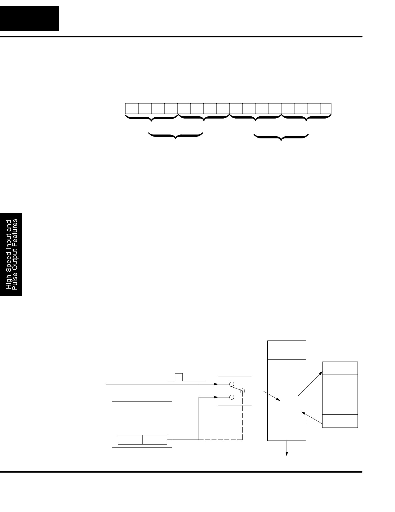
3-44
High-speed Input and Pulse Output Features
Recall that V7633 is the HSIO Mode Select register. Refer to the diagram below. Use
Setup for Mode 40
BCD 40 in the lower byte to select High-Speed Interrupt Mode. Use BCD 00 or 20 in
the upper byte as required. Combine the two bytes into a data word “xx40”, for writing
to V7633.
Memory Location V7633
Bits
15
14
13
12
11
10
9
8
7
6
5
4
3
2
1
0
0
0
1
0
0
0
0
0
0
1
0
0
0
0
0
0
2
0
4
0
Miscellaneous Setup (BCD)
HSIO Mode Setup (BCD)
00 = Power Up in Previous Mode
20 = Power Up in Run Mode Always
40 = High-Speed Interrupt
Choose the most convenient method of programming V7633 from the following:
S Include load and out instructions in your ladder program
S DirectSOFT32’s memory editor
S Use the Handheld Programmer D2-HPP
We recommend using the first method above so that the HSIO setup becomes an
integral part of your application program. An example program later in this section
shows how to to this.
Interrupts and the
Refer to the drawing below. The source of the interrupt may be external (X0), or the
Ladder Program
HSIO timer function. The setup parameter in V7634 serves a dual purpose:,
S It selects between the two interrupt sources, external (X0) or an internal
timer.
S In the case of the timer interrupt, it programs the interrupt timebase
between 5 and 999 mS.
The resulting interrupt uses label INT 0 in the ladder program. Be sure to include the
Enable Interrupt (ENI) instruction at the beginning of your program. Otherwise, the
interrupt routine will not be executed.
CPU Scan
Input
Update
Ladder
INT
Program
X0, External Interrupt
Execution
Interrupt
Routine
Program
current
TIMER
instruction
Interrupt source /
IRT
Time select
Input
Update
V7634
xxx4
DL105 PLC User Manual, 2nd Edition, Rev. A
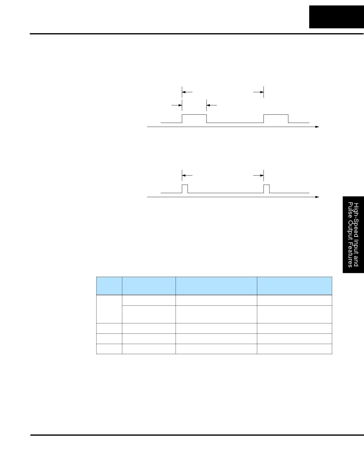
3-45
High-Speed Input and Pulse Output Features
Signal pulses at X0 must meet certain timing criteria to guarantee an interrupt will
External Interrupt
result. Refer to the timing diagram below. The input characteristics of X0 are fixed (it
Timing Parameters
is not a programmable filtered input). The minimum pulse width is 0.1 mS. There
must be some delay before the next interrupt pulse arrives, such that the interrupt
period cannot be smaller than 0.5 mS.
0.5 mS minimum
0.1 mS minimum
External
Interrupt
X0
Time
Timed Interrupt
When the timed interrupt is selected, the HSIO generates the interrupt to ladder
Parameters
logic. There is no interrupt “pulse width” in this case, but the interrupt period can be
adjusted from 5 to 999 mS.
5 mS to 999 mS
Timed
Interrupt
Time
X Input / Timed
The configurable discrete input options for High-Speed Interrupt Mode are listed in
the table below. Input X0 is the external interrupt when “0004” is in V7634. If you
INT Configuration
need a timed interrupt instead, then V7634 contains the interrupt time period, and
input X0 becomes a filtered input (uses X1’s filter time constant by default). Inputs
X1, X2, and X3 can only be filtered inputs, having individual configuration registers
and filter time constants. However, X0 will have the same filter time constant as X1
when the timed interrupt is selected.
Input
Configuration
Function
Hex Code
Register
Required
X0
V7634
External Interrupt
0004
Uses X1’s code
Filtered Input (when timed
0054 to 9994, which is
in V7635
interrupt is in use)
the timed INT timebase
X1
V7635
Filtered Input
xx06 (xx = filter time)
X2
V7636
Filtered Input
xx06 (xx = filter time)
X3
V7637
Filtered Input
xx06 (xx = filter time)
DL105 PLC User Manual, 2nd Edition, Rev. A
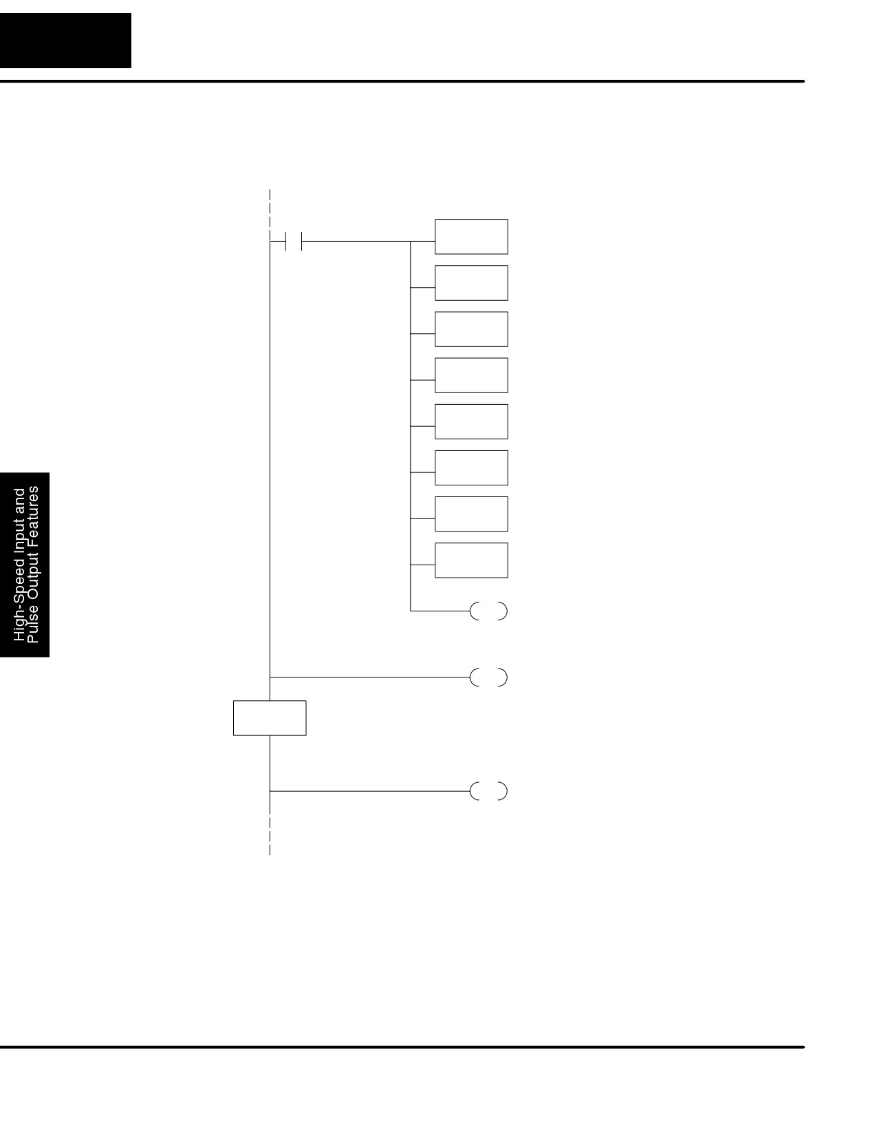
3-46
High-speed Input and Pulse Output Features
External Interrupt
The following program selects Mode 40, then selects the external interrupt option.
Program Example
Inputs X1, X2, and X3 are all configured as filtered inputs with a 10 mS time constant.
The program is otherwise generic, and may be adapted to your application.
DirectSOFT32
SP0
Load constant K40 into the accumulator. This
LD
selects Mode 40 as the HSIO mode.
K40
Mode 40
Output this constant to V7633, the location of the
OUT
HSIO Mode select register.
V7633
Load the constant K4 which is required to select the
External Interrupt
LD
external interrupt option. X0 is the interrupt input.
K4
Output this constant to V7634, configuring the
OUT
external interrupt option for X0.
V7634
Load the constant K1006 which is required to select
Filtered Inputs
LD
filtered inputs with a 10 mS filter time constant.
K1006
Output this constant to V7635, configuring X1.
OUT
V7635
Output this constant to V7636, configuring X2.
OUT
V7636
Output this constant to V7637, configuring X3.
OUT
V7637
INT Enable
ENI
Enable Interrupts at the beginning of the program.
Main Program
Insert Main Program rungs here for your application.
END
END coil marks the end of the main program..
INT
O0
The INT label marks the beginning of the interrupt
service routine program.
Interrupt Routine
Insert interrupt service routine rungs here for your
application.
IRT
Return to the main ladder program.
DL105 PLC User Manual, 2nd Edition, Rev. A
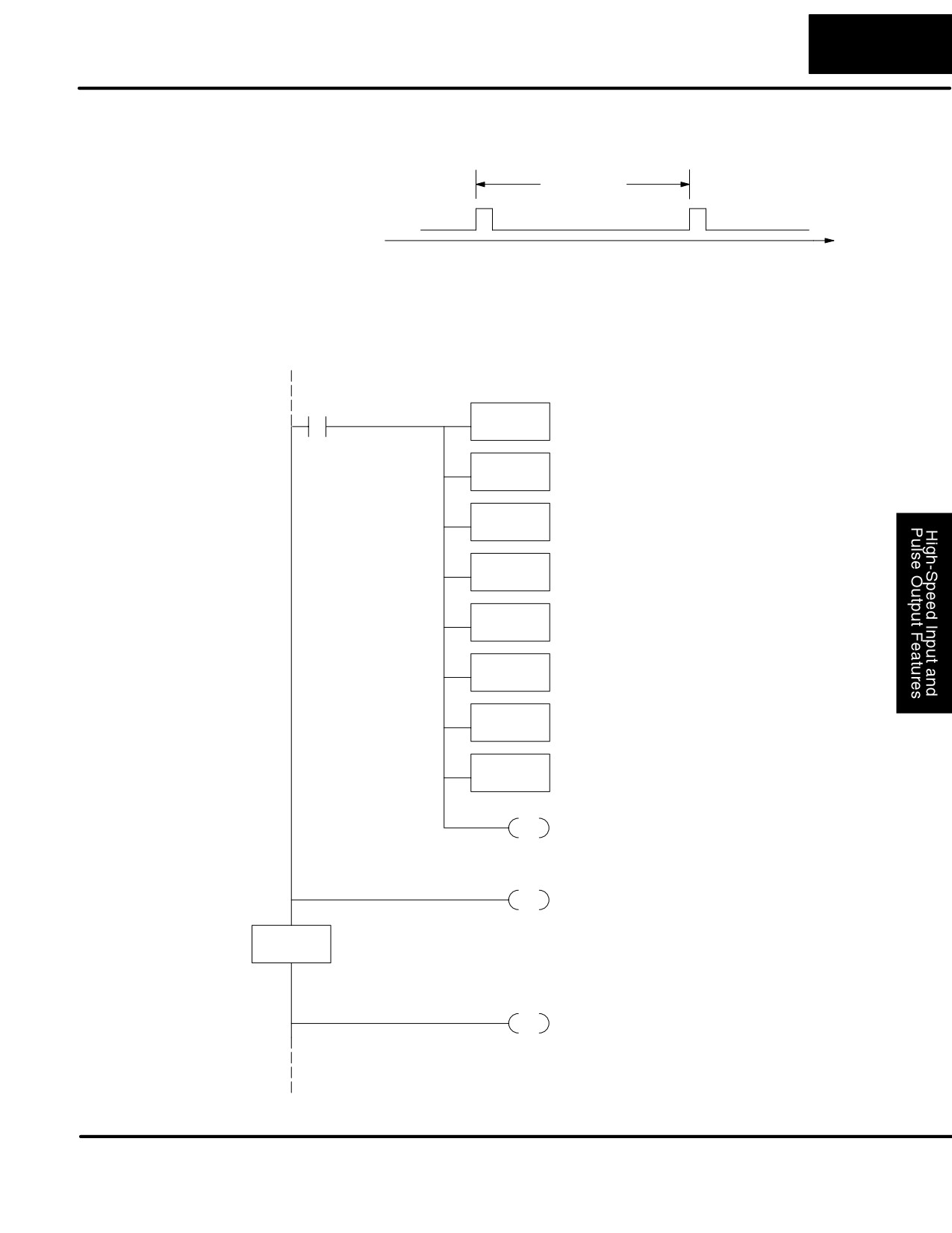
3-47
High-Speed Input and Pulse Output Features
Timed Interrupt
The following program selects Mode 40, then selects the timed interrupt option, with
Program Example
an interrupt period of 100 mS.
100 mS
Timed
Interrupt
Time
Inputs X0, X1, X2, and X3 are all configured as filtered inputs with a 10 mS time
constant. Note that X0 uses the time constant from X1. The program is otherwise
generic, and may be adapted to your application.
DirectSOFT32
SP0
Load constant K40 into the accumulator. This
LD
selects Mode 40 as the HSIO mode.
K40
Mode 40
Output this constant to V7633, the location of the
OUT
HSIO Mode select register.
V7633
Load the constant K1004 which is required to select
Timed Interrupt
LD
the timed interrrupt option, with a period of 100 mS.
K1004
Output this constant to V7634, configuring the timed
OUT
interrupt for 100 mS period.
V7634
Load the constant K1006 which is required to select
Filtered Inputs
LD
filtered inputs with a 10 mS filter time constant.
K1006
Output this constant to V7635, configuring X1 and X0
OUT
V7635
Output this constant to V7636, configuring X2.
OUT
V7636
Output this constant to V7637, configuring X3.
OUT
V7637
INT Enable
ENI
Enable Interrupts at the beginning of the program.
Main Program
Insert Main Program rungs here for your application.
END
END coil marks the end of the main program..
INT
O0
The INT label marks the beginning of the interrupt
service routine program.
Interrupt Routine
Insert interrupt service routine rungs here for your
application.
IRT
Return to the main ladder program.
DL105 PLC User Manual, 2nd Edition, Rev. A
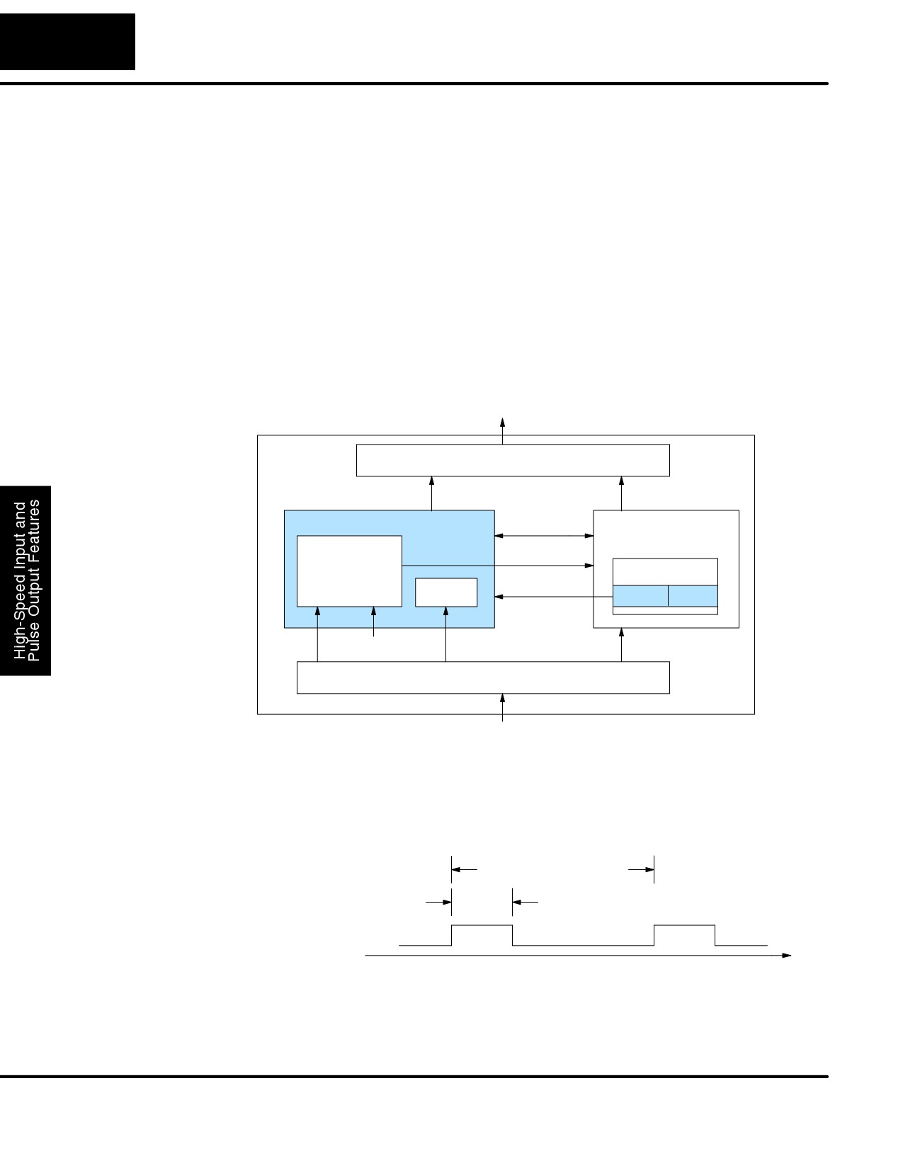
3-48
High-speed Input and Pulse Output Features
Mode 50: Pulse Catch Input
Purpose
The HSIO circuit has a pulse-catch mode of operation. It monitors the signal on input
X0, preserving the occurrence of a narrow pulse. The purpose of the pulse catch
mode is to enable the ladder program to “see” an input pulse which is shorter in
duration than the current scan time. The HSIO circuit latches the input event on input
X0 for one scan, and presents it to ladder logic through special relay SP100 contact.
This contact automatically goes off after one scan. Note that the ladder program
cannot read the status of X0 directly.
Functional Block
Refer to the block diagram below. When the lower byte of HSIO Mode register V7633
Diagram
contains a BCD “50”, the pulse catch mode in the HSIO circuit is enabled. X0
automatically becomes the pulse catch input, which sets the latch on each rising
edge. The HSIO resets the latch at the end of the next CPU scan. The latch output is
available to the ladder program through the special relay contact SP100. Inputs X1,
X2, and X3 are available as filtered discrete inputs.
DL105
Output Circuit
PLC
Y0, Y1
Y2 - Y7
HSIO
CPU
I/O data
LATCH
SP100
VĆmemory
Mode Select
Set Reset
FILTER
V7633
xx50
X0
scan
X1, X2, X3
X4- X11
Input Circuit
Signal pulses at X0 must meet certain timing criteria to guarantee a pulse capture
Pulse Catch
will result. Refer to the timing diagram below. The input characteristics of X0 are
Timing Parameters
fixed (it is not a programmable filtered input). The minimum pulse width is 0.1 mS.
There must be some delay before the next pulse arrives, such that the pulse period
cannot be smaller than 0.5 mS. If the pulse period is smaller than 0.5 mS, the next
pulse will be considered part of the current pulse.
0.5 mS minimum
0.1 mS minimum
Pulse
Input
X0
Time
Note that the pulse catch and filtered input functions are opposite in nature. The
pulse catch feature on X0 seeks to capture narrow pulses, while the filter input
feature on X1, X2, and X3 seeks to reject narrow pulses.
DL105 PLC User Manual, 2nd Edition, Rev. A
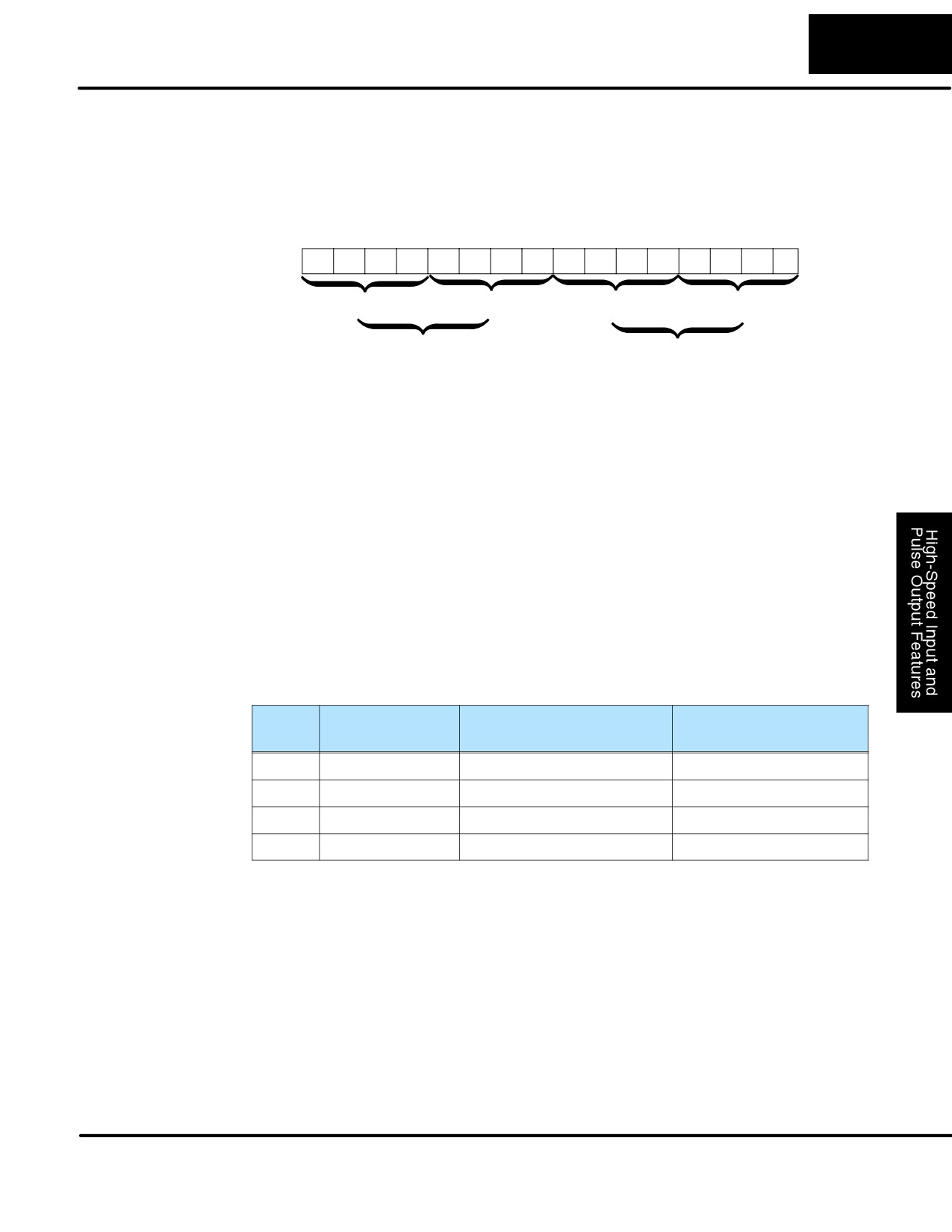
3-49
High-Speed Input and Pulse Output Features
Recall that V7633 is the HSIO Mode Select register. Refer to the diagram below. Use
Setup for Mode 50
BCD 50 in the lower byte to select High-Speed Counter Mode. Use BCD 00 or 20 in
the upper byte as required. Combine the two bytes into a data word “xx50”, for writing
to V7633.
Memory Location V7633
Bits
15
14
13
12
11
10
9
8
7
6
5
4
3
2
1
0
0
0
1
0
0
0
0
0
0
1
0
1
0
0
0
0
2
0
5
0
Miscellaneous Setup (BCD)
HSIO Mode Setup (BCD)
00 = Power Up in Previous Mode
20 = Power Up in Run Mode Always
50 = Pulse Catch Input
Choose the most convenient method of programming V7633 from the following:
S Include load and out instructions in your ladder program
S DirectSOFT32’s memory editor
S Use the Handheld Programmer D2-HPP
We recommend using the first method above so that the HSIO setup becomes an
integral part of your application program. An example program later in this section
shows how to to this.
X Input
The configurable discrete input options for Pulse Catch Mode are listed in the table
Configuration
below. Input X0 is the pulse input, and must have “0005” loaded into it configuration
register V7634. Inputs X1, X2, and X3 can only be filtered inputs. Each input has its
own configuration register and filter time constant.
Input
Configuration
Function
Hex Code
Register
Required
X0
V7634
Pulse Catch Input
0005
X1
V7635
Filtered Input
xx06 (xx = filter time)
X2
V7636
Filtered Input
xx06 (xx = filter time)
X3
V7637
Filtered Input
xx06 (xx = filter time)
DL105 PLC User Manual, 2nd Edition, Rev. A