DL105 Micro PLC. User Manual (2003) - page 2
2-14
Installation, Wiring, and Specifications
In many cases, using the built-in auxiliary +24VDC supply can result in a cost
savings for your control system. It can power combined loads up to 500 mA, which is
enough to eliminate the need for an additional power supply in some applications. If
you are the system designer for your application, you may be able to select and
design in field devices which can use the +24VDC auxiliary supply.
Powering I/O
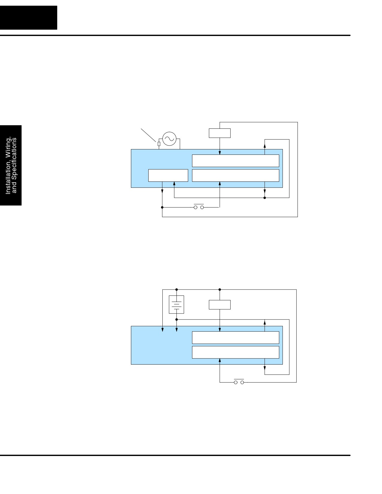
All AC-powered DL105 Micro PLCs feature the internal auxiliary supply. If input
Circuits with the
devices AND output loads need +24VDC power, the auxiliary supply can power both
Auxiliary Supply
circuits as shown in the following diagram.
Fuse or
AC Power
Circuit
Loads
Breaker
DL105
PLC
Power Input
8 Discrete Outputs Commons
+24VDC Out
10 Discrete Inputs
Commons
+
-
DC-powered DL105 Micro PLCs are designed for application environments in which
low-voltage DC power is more readily available than AC. These include a wide range
of battery-powered applications, such as remotely-located control, in vehicles,
portable machines, etc. For this application type, all input devices and output loads
typically use the same DC power source. The F1-130DR-D and F1-130DD-D are
compatible with either +12VDC or +24VDC systems. Typical wiring for DC-powered
applications is shown in the following diagram.
+
DC Power
Loads
-
+
-
DL105
Power Input
8 Discrete Outputs Commons
PLC
10 Discrete Inputs
Commons
DL105 PLC User Manual, 2nd Edition, Rev. A
2-15
Installation, Wiring, and Specifications
Powering I/O
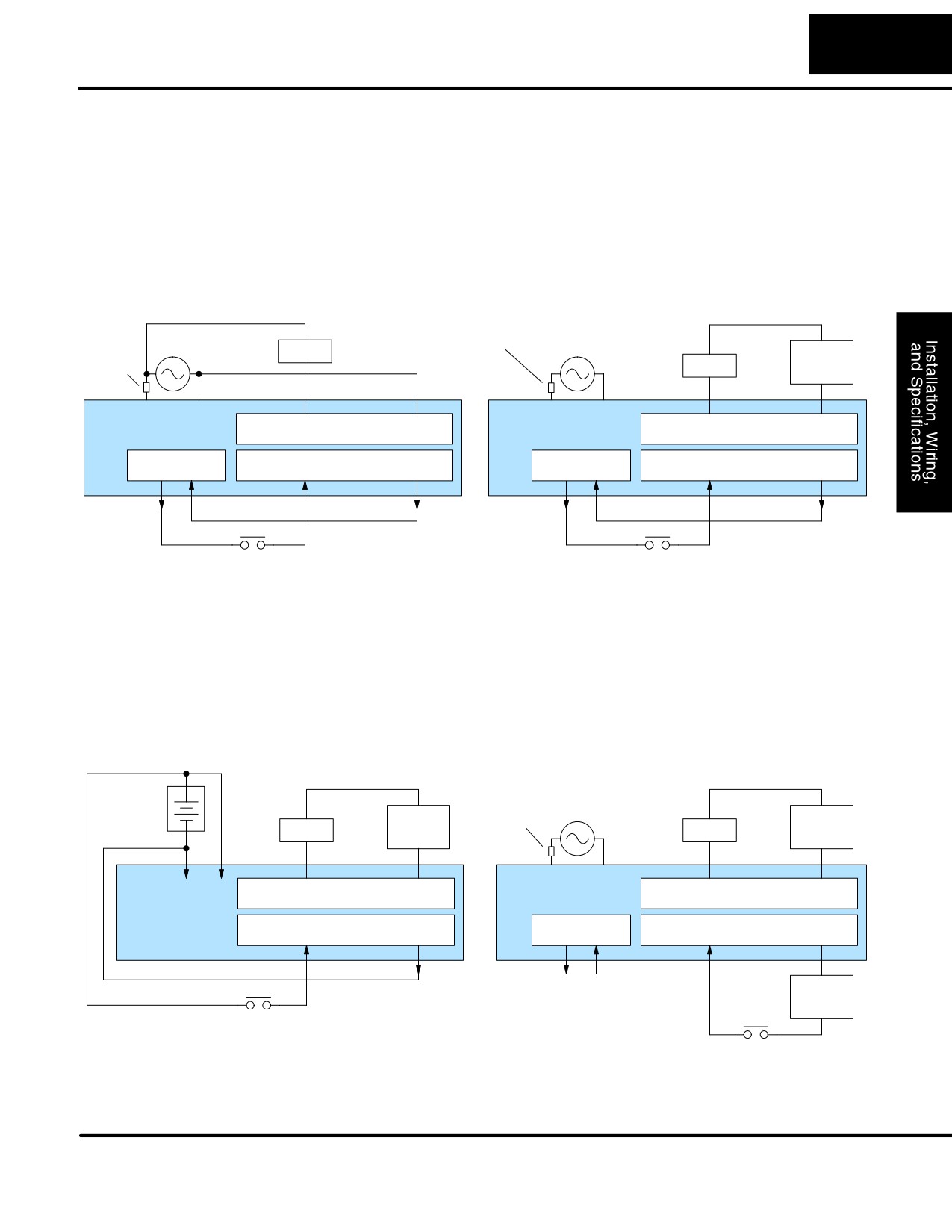
In some applications it will be necessary to power the input devices from one power
Circuits Using
source, and to power output loads from another source. Loads often require
high-energy AC power, while input sensors use low-energy DC. If a machine
Separate Supplies
operator is likely to come in close contact with input wiring, then safety reasons also
require isolation from high-energy output circuits. It is most convenient if the loads
can use the same power source as the Micro PLC, and the input sensors can use the
auxiliary supply, as shown to the left in the figure below.
If the loads cannot be powered from the Micro PLC supply, then a separate supply
must be used as shown to the right in the figure below.
Fuse or
Fuse or
AC Power
AC Power
Circuit
Loads
Circuit
Load
Breaker
Loads
Breaker
Supply
DL105
DL105
Power Input
8 Discrete Outputs Commons
Power Input
8 Discrete Outputs Commons
PLC
PLC
+24VDC Out
10 Discrete Inputs
Commons
+24VDC Out
10 Discrete Inputs
Commons
+
-
+
-
Some applications will use the Micro PLC power source to also power the input
circuit. This typically occurs on a DC-powered DL105, as shown in the drawing
below to the left. The inputs share the PLC power source supply, while the outputs
have their own separate supply.
A worst-case scenario, from a cost and complexity view-point, is an application
which requires separate power sources for the PLC, input devices, and output loads.
The example wiring diagram below on the right shows how this can work, but also
that the auxiliary supply out is an unused resource. For these reasons, you’ll
probably want to avoid this situation if possible.
Fuse or
+
Circuit
DC Power
AC Power
Load
Breaker
Load
-
Loads
Loads
Supply
Supply
-
+
DL105
DL105
Pow-
8 Discrete Outputs Commons
Power Input
8 Discrete Outputs Commons
PLC
PLC
er
Input
10 Discrete Inputs
Commons
+24VDC Out
10 Discrete Inputs
Commons
Input
Supply
DL105 PLC User Manual, 2nd Edition, Rev. A
2-16
Installation, Wiring, and Specifications
Connecting
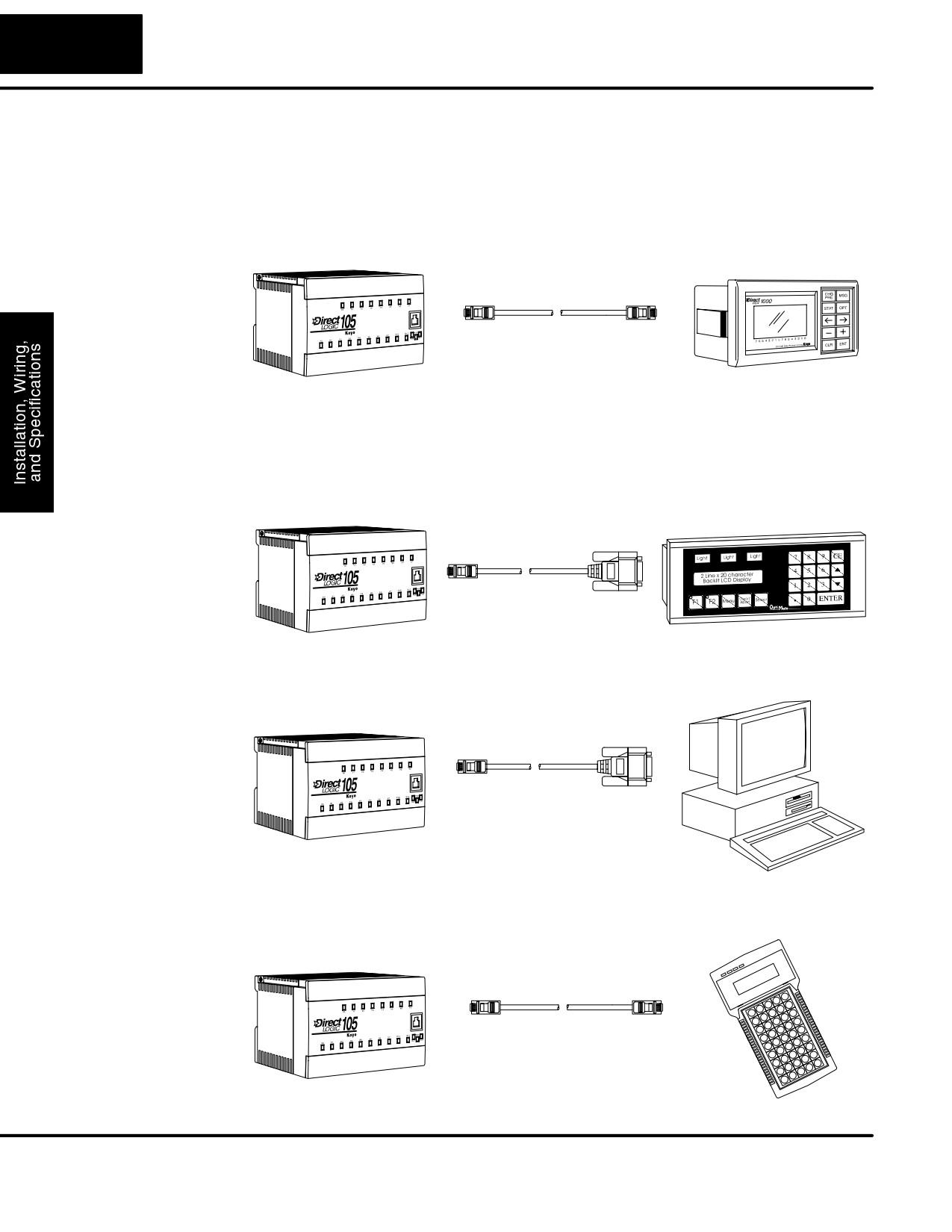
Operator interfaces require data and power connections. Operator interfaces with a
Operator Interface
large CRT usually require separate AC power. However, small operator interface
Devices
devices like the popular DV-1000 Data Access Unit and the Optimation panels may
be powered directly from the DL105 Micro PLC.
Connect the DV-1000 to the DL105 Micro PLC COM1 port using the cable shown
below. A single cable contains transmit/receive data wires and +5V power.
DL105 Micro PLC
DV-1000
RJ12
RJ12
phone style
phone style
Use cable part no.
DV-1000CBL
Optimation operator interface panels require separate power and communications
connections. Connect the DL105 COM1 port to the 15-pin D-shell connector on the
rear of the Optimation panel using the cable shown below. Optimation panels require
8-30VDC power, so use separate wiring to connect the +24VDC supply output on
AC-powered DL105 PLCs. Use external +24VDC power for DC-powered DL105s.
DL105 Micro PLC
Optimation Panel
RJ12
15-pin D-shell
phone style
male
Use cable part no.
OP-2CBL
Connecting
DL105 Micro PLCs can be programmed with either a handheld programmer or with
Programming
DirectSOFT32 on a PC. Connect the DL105 to a PC using the cable shown below.
Devices
RJ12
9-pin D-shell
DL105 Micro PLC
phone style
female
Use cable part no.
D2-DSCBL
The D2-HPP Handheld Programmer comes with a communications cable. For a
replacement part, use the cable shown below.
DL105 Micro PLC
RJ12
RJ12
D2-HPP
phone style
phone style
(cable comes with HPP)
For replacement
cable, use part no.
DV-1000CBL
DL105 PLC User Manual, 2nd Edition, Rev. A
2-17
Installation, Wiring, and Specifications
Sinking / Sourcing
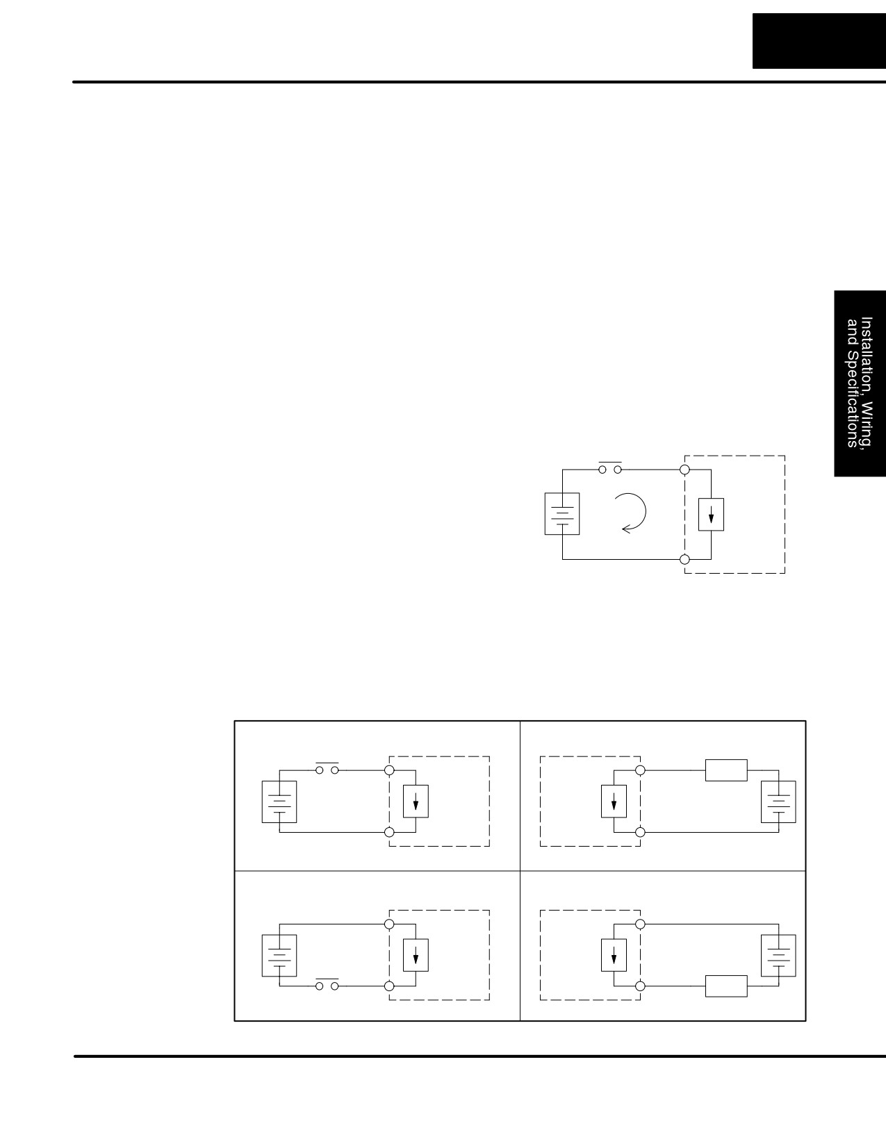
Before going further in our study of wiring strategies, we must have a solid
Concepts
understanding of “sinking” and “sourcing” concepts. Use of these terms occurs
frequently in input or output circuit discussions. It is the goal of this section to make
these concepts easy to understand, further ensuring your success in installation.
First we give the following short definitions, followed by practical applications.
Sinking = Path to supply ground (-)
Sourcing = Path to supply source (+)
First you will notice that these are only associated with DC circuits and not AC,
because of the reference to (+) and (-) polarities. Therefore, sinking and sourcing
terminology only applies to DC input and output circuits. Input and output points that
are either sinking or sourcing can conduct current in only one direction. This means it
is possible to connect the external supply and field device to the I/O point with current
trying to flow in the wrong direction, and the circuit will not operate. However, we can
successfully connect the supply and field device every time by understanding
“sourcing” and “sinking”.
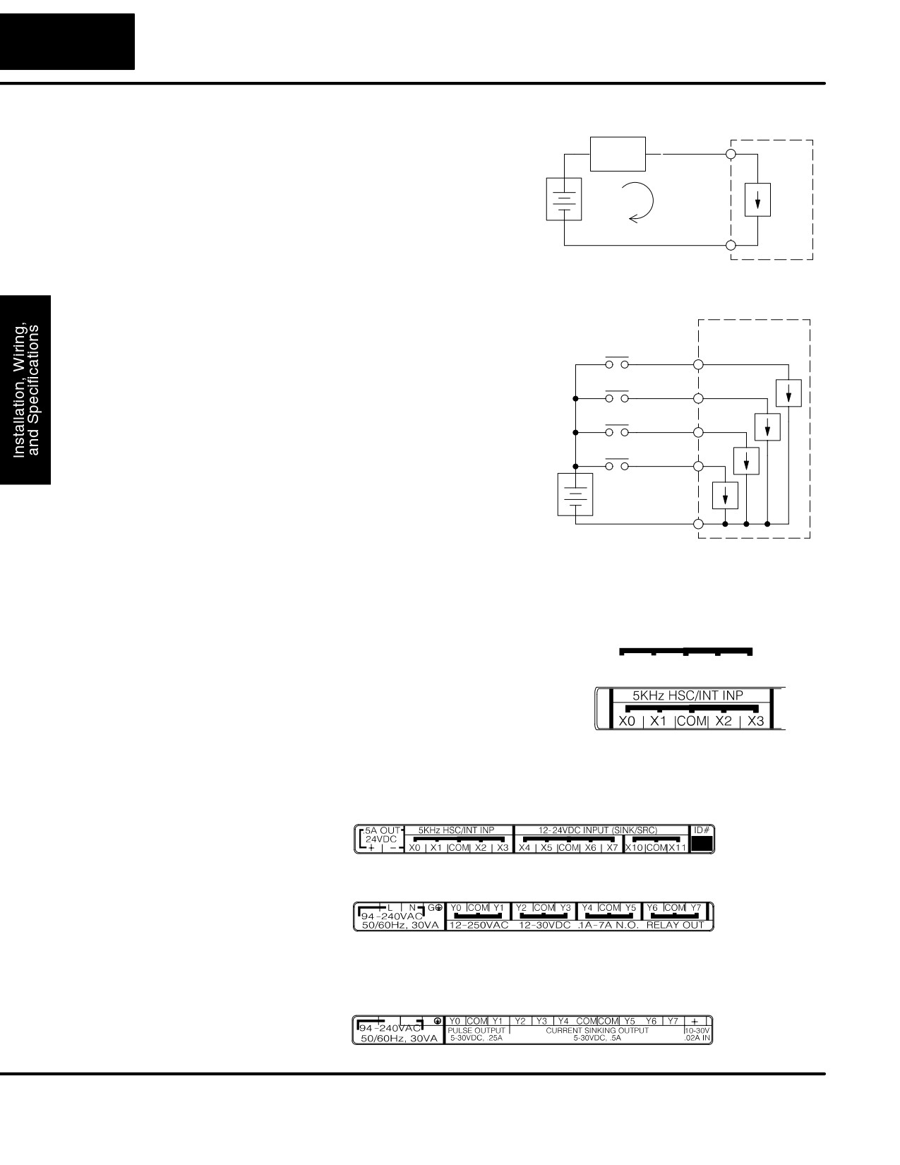
For example, the figure to the right depicts
PLC
a “sinking” input. To properly connect the
Input
external supply, we just have to connect it
(sinking)
so the the input provides a path to ground
+
(-). So, we start at the PLC input terminal,
Input
follow through the input sensing circuit,
Sensing
-
exit at the common terminal, and connect
Common
the supply (-) to the common terminal. By
adding the switch, between the supply (+)
and the input, we have completed the
circuit. Current flows in the direction of the
arrow when the switch is closed.
By applying the circuit principle above to the four possible combinations of
input/output sinking/sourcing types, we have the four circuits as shown below.
DL105 Micro PLCs provide all except the sourcing output I/O circuit types.
Sinking Input
Sinking Output
PLC
PLC
Input
Output
Load
+
+
Input
Output
Sensing
Switch
–
-
Common
Common
Sourcing Input
Sourcing Output
PLC
PLC
Common
Common
+
+
Input
Output
Sensing
Switch
–
-
Input
Output
Load
DL105 PLC User Manual, 2nd Edition, Rev. A
2-18
Installation, Wiring, and Specifications
I/O “Common”
In order for a PLC I/O circuit to operate,
PLC
Terminal Concepts
current must enter at one terminal and exit
Field
Main Path
at another. This means at least two
Device
I/O
(I/O Point)
Circuit
terminals are associated with every I/O
+
point. In the figure to the right, the Input or
Output terminal is the main path for the
-
current. One additional terminal must
Return Path
provide the return path to the power
supply.
If we had unlimited space and budget for
PLC
I/O terminals, then every I/O point could
Input
have two dedicated terminals just as the
Sensing
Input 1
figure above shows. However, providing
this level of flexibility is not practical or
Input 2
even necessary for most applications. So,
most Input or Output point groups on
Input 3
PLCs share the return path among two or
more I/O points. The figure to the right
Input 4
shows a group (or bank) of 4 input points
+
which share a common return path. In this
way, the four inputs require only five
-
Common
terminals instead of eight.
Note: In the circuit above, the current in the common path is 4 times any channel’s
input current when all inputs are energized. This is especially important in output
circuits, where heavier gauge wire is sometimes necessary on commons.
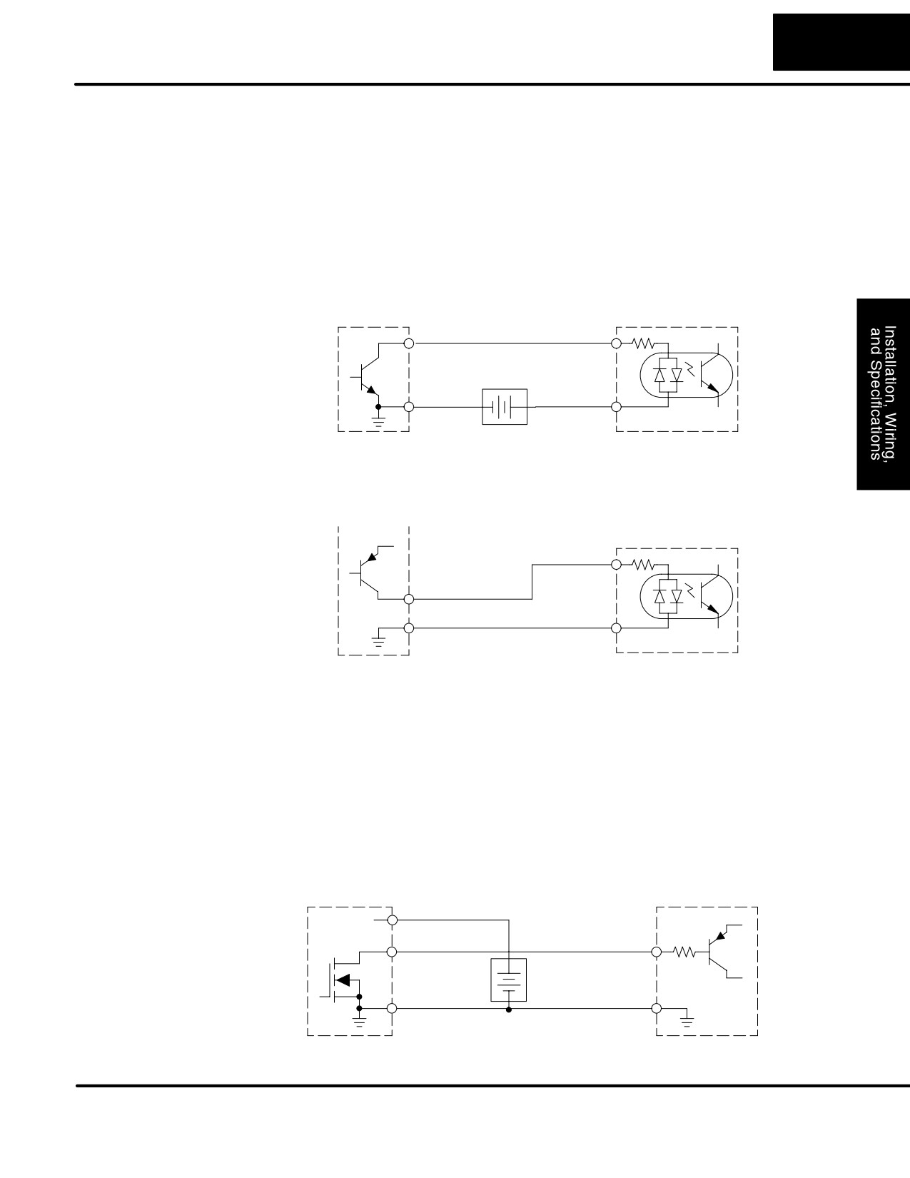
Most DL105 input and output circuits are
I/O Common Grouping Bar
grouped into banks that share a common
return path. The best indication of I/O
common grouping is on the wiring label.
The I/O common grouping bar, labeled at
the right, occurs in the section of wiring
label below it. It indicates X0, X1, X2, and
X3 share the common terminal located
between X1 and X2.
The following complete label shows two banks of four inputs and one bank of two.
The following label for relay outputs shows four banks of two output points each.
The last label below for DC outputs has no common grouping bar. In this unique
case, all eight outputs share the same electrical common. The common is available
on three terminals, so there is a physical place to connect each point’s common wire.
DL105 PLC User Manual, 2nd Edition, Rev. A
2-19
Installation, Wiring, and Specifications
Connecting DC I/O
In the previous section on Sourcing and Sinking concepts, we explained that DC I/O
to “Solid State”
circuits sometimes will only allow current to flow one way. This is also true for many of
Field Devices
the field devices which have solid-state (transistor) interfaces. In other words, field
devices can also be sourcing or sinking. When connecting two devices in a series
DC circuit, one must be wired as sourcing and the other as sinking.
Solid State
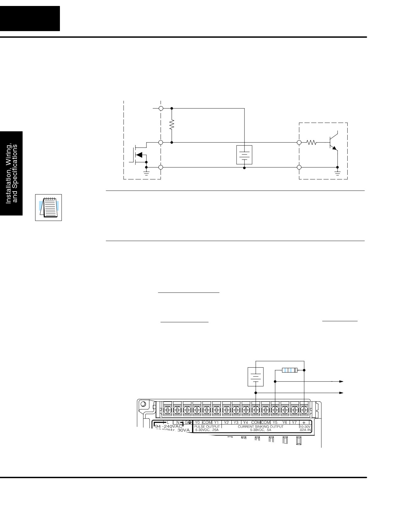
The DL105’s DC inputs are flexible in that they detect current flow in either direction,
Input Sensors
so they can be wired as either sourcing or sinking. In the following circuit, a field
device has an open-collector NPN transistor output. It sinks current from the PLC
input point, which sources current. The power supply can be the +24 auxiliary supply
or another supply (+12 VDC or +24VDC), as long as the input specifications are met.
Field Device
PLC DC Input
Output
Input
(sinking)
(sourcing)
Supply
Ground
-
+
Common
In the next circuit, a field device has an open-emitter PNP transistor output. It
sources current to the PLC input point, which sinks the current back to ground. Since
the field device is sourcing current, no additional power supply is required.
Field Device
+V
PLC DC Input
Input
(sinking)
Output (sourcing)
Ground
Common
Solid State
Sometimes an application requires connecting a PLC output point to a solid state
Output Loads
input on a device. This type of connection is usually made to carry a low-level signal,
not to send DC power to an actuator.
The DL105’s DC outputs are sinking-only. This means that each DC output provides
a path to ground when it is energized. Also, remember that all eight outputs have the
same electrical common, even though there are three common terminal screws.
Finally, recall that the DC output circuit requires power (10 - 30 VDC) from an
external power source.
In the following circuit, the PLC output point sinks current to the output common
when energized. It is connected to a sourcing input of a field device input.
PLC DC Output
Field Device
Power
+DC pwr
+V
Output
Input
(sinking)
(sourcing)
+
10-30 VDC
Common
-
Ground
DL105 PLC User Manual, 2nd Edition, Rev. A
2-20
Installation, Wiring, and Specifications
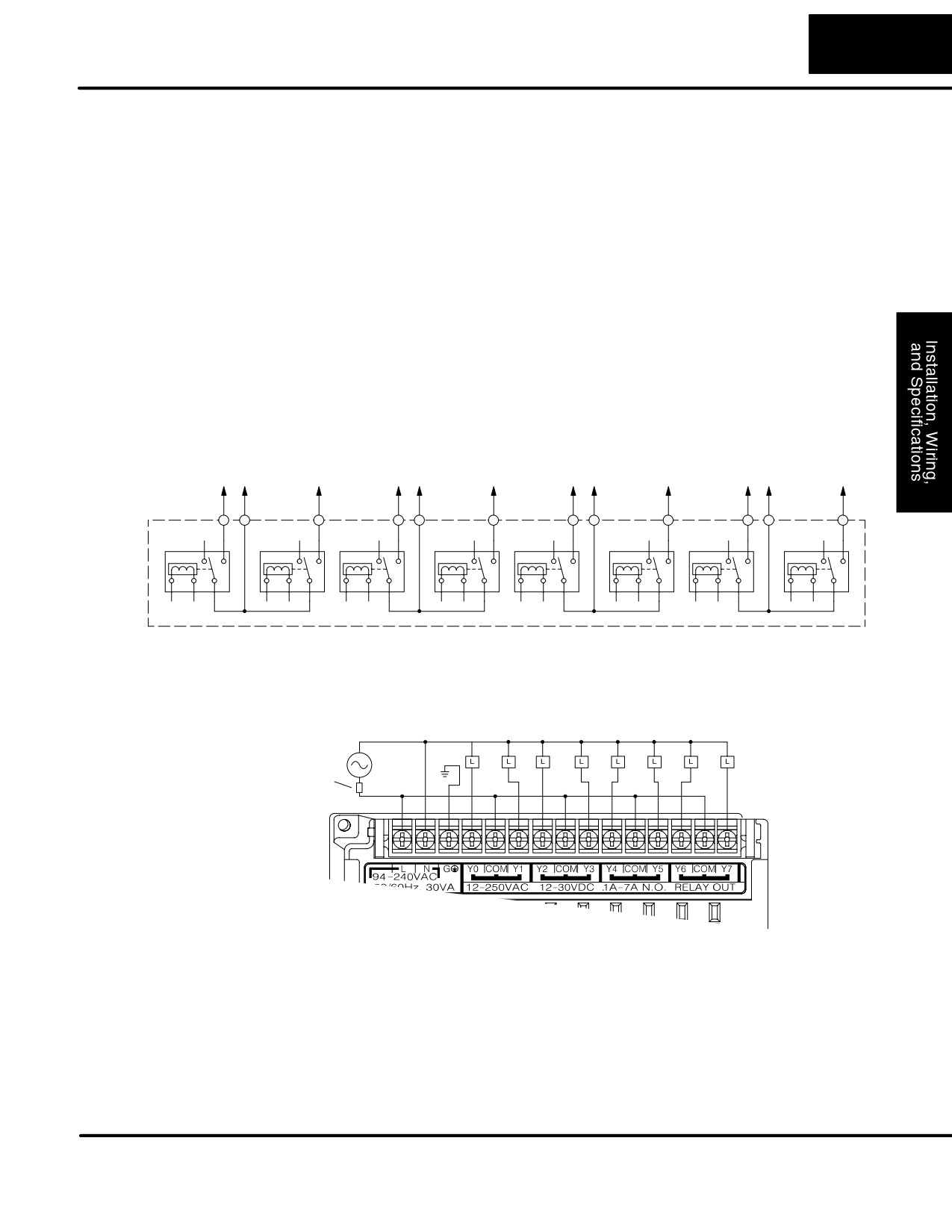
In the next example we connect a PLC DC output point to the sinking input of a field
device. This is a bit tricky, because both the PLC output and field device input are
sinking type. Since the circuit must have one sourcing and one sinking device, we
add sourcing capability to the PLC output by using a pull-up resistor. In the circuit
below, we connect Rpull-up from the output to the DC output circuit power input.
PLC DC Output
Power
+DC pwr
Field Device
R
pull-up
(sourcing)
(sinking)
Output
Input
R input
+
(sinking)
Supply
Common
-
Ground
NOTE: DO NOT attempt to drive a heavy load (>25 mA) with this pull-up method.
NOTE 2: Using the pull-up resistor to implement a sourcing output has the effect of
inverting the output point logic. In other words, the field device input is energized
when the PLC output is OFF, from a ladder logic point-of-view. Your ladder program
must comprehend this and generate an inverted output. Or, you may choose to
cancel the effect of the inversion elsewhere, such as in the field device.
It is important to choose the correct value of R pull-up. In order to do so, we need to
know the nominal input current to the field device (I input) when the input is energized.
If this value is not known, it can be calculated as shown (a typical value is 15 mA).
Then use I input and the voltage of the external supply to compute R pull-up. Then
calculate the power Ppull-up (in watts), in order to size R pull-up properly.
V input (turn-on)
I input
=
R input
2
V supply - 0.7
V supply
R pull-up
=
-
R input
P pull-up
=
I input
R pullup
The drawing below shows the actual wiring of the DL105 Micro PLC to the supply
and pull-up resistor.
+
Supply
Output
-
Common
DL105 PLC User Manual, 2nd Edition, Rev. A
2-21
Installation, Wiring, and Specifications
Relay Output
The F1-130AR, F1-130DR/F1-130DR-CE, and F1-130DR-D models feature
Wiring Methods
relay outputs. Relays are best for the following applications:
S Loads that require higher currents than the solid-state DL105 outputs
can deliver
S Cost-sensitive applications
S Some output channels need isolation from other outputs (such as when
some loads require AC while others require DC)
Some applications in which NOT to use relays:
S Loads that require currents under 10 mA
S Loads which must be switched at high speed and duty cycle
Assuming relays are right for your application, we’re now ready to explore various
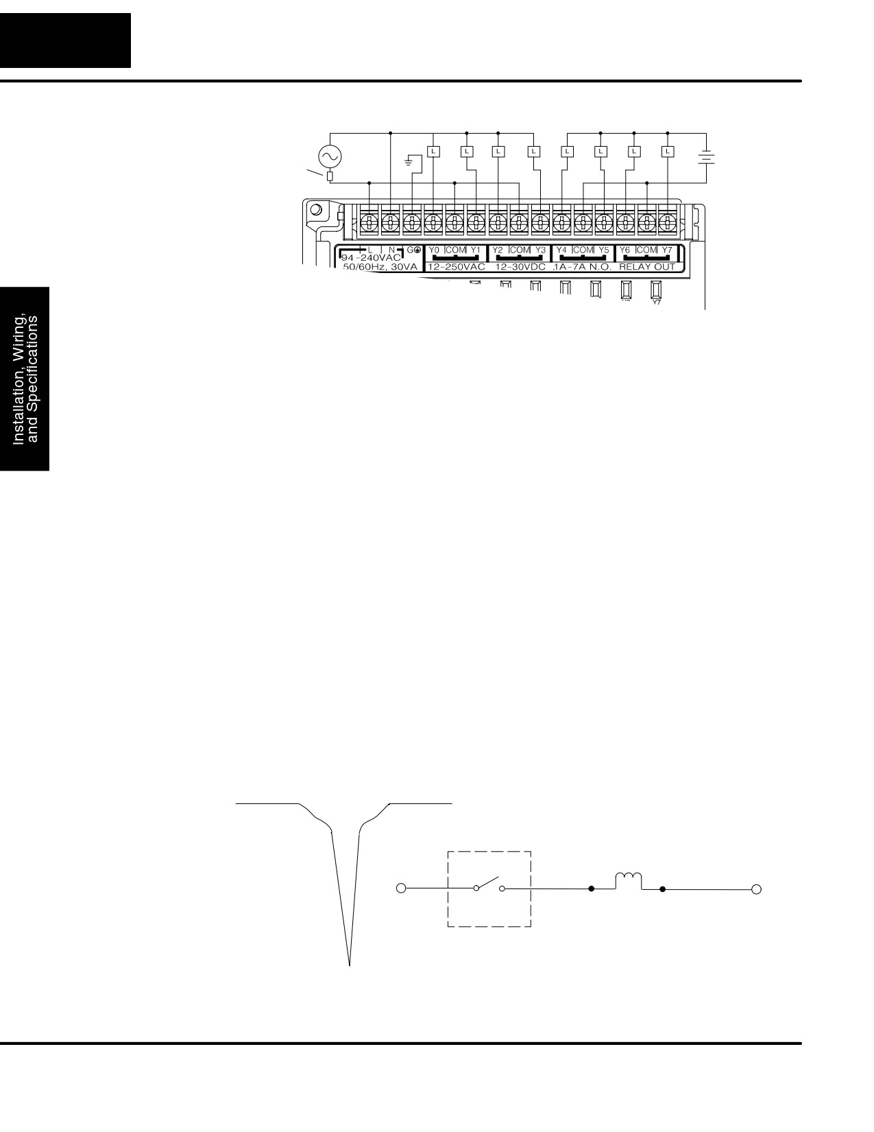
ways to wire relay outputs to the loads. Note that there are eight normally-open
SPST relays available. They are organized into four pairs with individual commons.
The figure below shows the relays and the internal wiring of the PLC. Note that each
pair is isolated from the other three relay pairs.
Y0
Com
Y1
Y2
Com
Y3
Y4
Com
Y5
Y6
Com
Y7
In the circuit below, all loads use the same AC power supply which powers the DL105
PLC. In this example, all commons are connected together.
Output Point Wiring
Fuse or
Neutral
Ground
Circuit
Breaker
Line
In the circuit on the following page, loads for Y0 - Y3 use the same AC power supply
which powers the DL105 PLC. Loads for Y4 - Y7 use a separate DC supply. In this
example, the commons are separated according to which supply powers the
associated load.
DL105 PLC User Manual, 2nd Edition, Rev. A
2-22
Installation, Wiring, and Specifications
Output Point Wiring
Fuse or
Neutral
Ground
-
Circuit
Breaker
+
Line
Surge Suppresion
Inductive load devices (devices with a coil) generate transient voltages when
For Inductive
de-energized with a relay contact. When a relay contact is closed it “bounces”, which
Loads
energizes and de-energizes the coil until the “bouncing” stops. The transient
voltages generated are much larger in amplitude than the supply voltage, especially
with a DC supply voltage.
When switching a DC-supplied inductive load the full supply voltage is always
present when the relay contact opens
(or
“bounces”). When switching an
AC-supplied inductive load there is one chance in 60 (60 Hz) or 50 (50 Hz) that the
relay contact will open (or “bounce”) when the AC sine wave is zero crossing. If the
voltage is not zero when the relay contact opens there is energy stored in the
inductor that is released when the voltage to the inductor is suddenly removed. This
release of energy is the cause of the transient voltages.
When inductive load devices (motors, motor starters, interposing relays, solenoids,
valves, etc.) are controlled with relay contacts, it is recommended that a surge
suppression device be connected directly across the coil of the field device. If the
inductive device has plug-type connectors, the suppression device can be installed
on the terminal block of the relay output.
Transient Voltage Suppressors (TVS or transorb) provide the best surge and
transient suppression of AC and DC powered coils, providing the fastest response
with the smallest overshoot.
Metal Oxide Varistors
(MOV) provide the next best surge and transient
suppression of AC and DC powered coils.
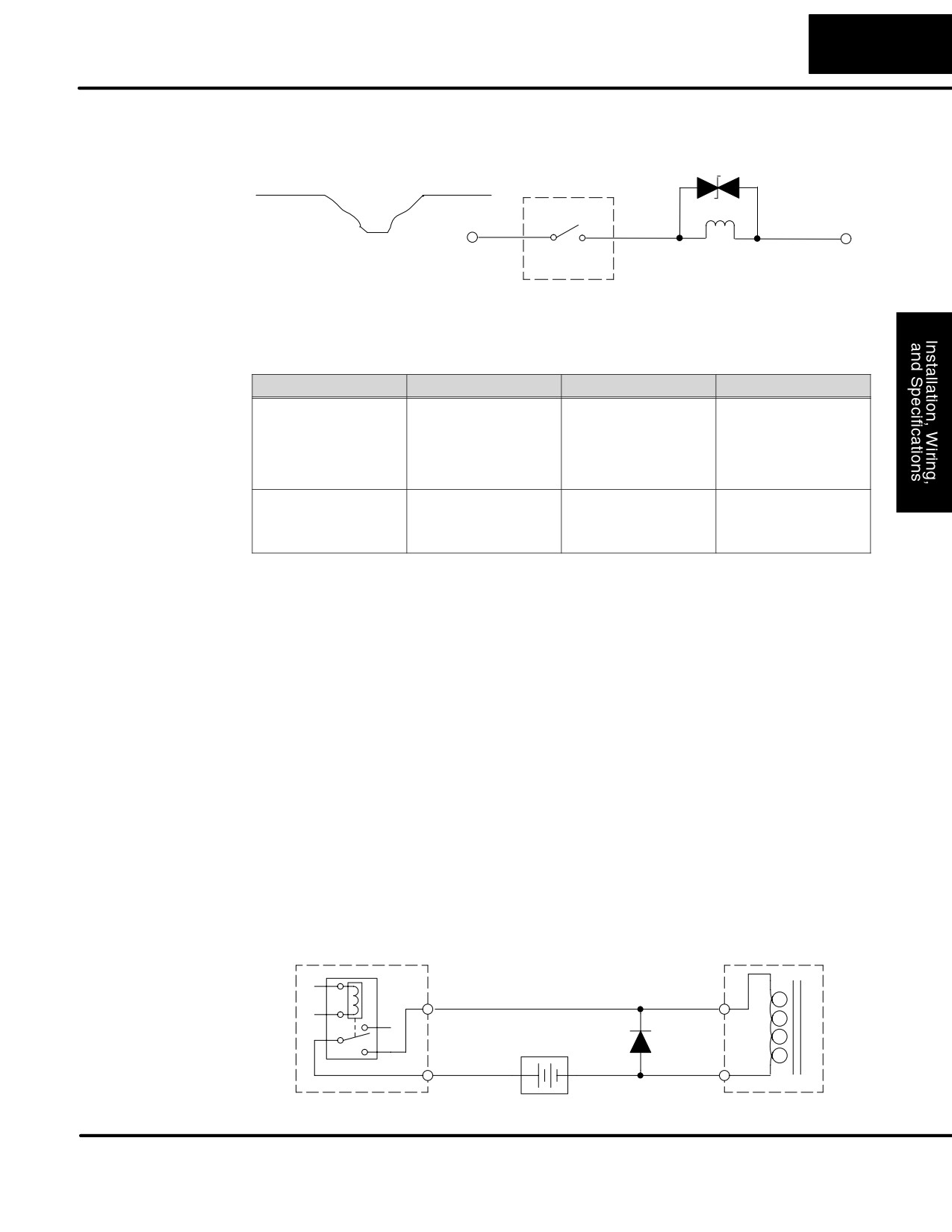
For example, the waveform in the figure below shows the energy released when
opening a contact switching a 24 VDC solenoid. Notice the large voltage spike.
+24 VDC
+24 VDC
-24 VDC
Module Relay Contact
–324 VDC
DL105 PLC User Manual, 2nd Edition, Rev. A
2-23
Installation, Wiring, and Specifications
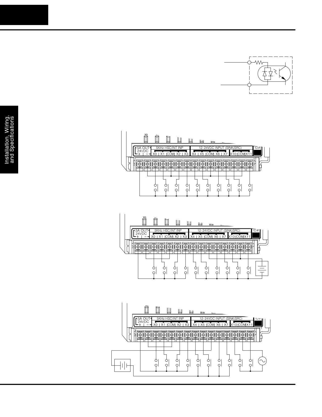
This figure shows the same circuit with a transorb (TVS) across the coil. Notice that
the voltage spike is significantly reduced.
+24 VDC
+24 VDC
-24 VDC
–42 VDC
Module Relay Contact
Use the following table to help select a TVS or MOV suppressor for your application
based on the inductive load voltage.
hhVendor / Catalog
Type (TVS, MOV, Diode)
Inductive Load Voltage
Part Number
General Instrument
TVS
110/120 VAC
P6KE180CAGICT-ND
Transient Voltage
TVS
220/240 VAC
P6KE350CA
Suppressors, LiteOn
Diodes; from DigiKey
TVS
12/24 VDC or VAC
P6K30CAGICT-ND
Catalog; Phone:
Diode
12/24 VDC or VAC
1N4004CT-ND
1-800-344-4539
Harris Metal Oxide
MOV
110/120 VAC
V150LA20C
Varistors; from Newark
MOV
220/240 VAC
V250LA20C
Catalog; Phone:
1-800-463-9275
Prolonging Relay
Relay contacts wear according to the amount of relay switching, amount of spark
Contact Life
created at the time of open or closure, and presence of airborne contaminants.
There are some steps you can take to help prolong the life of relay contacts, such as
switching the relay on or off only when it is necessary, and if possible, switching the
load on or off at a time when it will draw the least current. Also, take measures to
suppress inductive voltage spikes from inductive DC loads such as contactors and
solenoids.
For inductive loads in DC circuits we recommend using a suppression diode as
shown in the following diagram (DO NOT use this circuit with an AC power supply).
When the load is energized the diode is reverse-biased (high impedance). When the
load is turned off, energy stored in its coil is released in the form of a negative-going
voltage spike. At this moment the diode is forward-biased (low impedance) and
shunts the energy to ground. This protects the relay contacts from the high voltage
arc that would occur just as the contacts are opening.
Place the diode as close to the inductive field device as possible. Use a diode with a
peak inverse voltage rating (PIV) at least 100 PIV, 3A forward current or larger. Use a
fast-recovery type (such as Schottky type). DO NOT use a small-signal diode such
as 1N914, 1N941, etc. Be sure the diode is in the circuit correctly before operation. If
installed backwards, it short-circuits the supply when the relay energizes.
Inductive Field Device
PLC Relay Output
Output
Input
Supply
Common
+
-
Common
DL105 PLC User Manual, 2nd Edition, Rev. A
2-24
Installation, Wiring, and Specifications
DC Input Wiring
DL105 Micro PLCs with DC inputs are particularly
PLC DC Input
Methods
flexible because they can be either sinking or
Input
sourcing. The dual diodes (shown to the right) allow
current to flow in either direction. The inputs accept
either 10 - 26.4 VDC or 21.6 - 26.4 VAC. That’s
Common
right, either AC or DC voltages will work. The target
applications are +12 VDC, +24 VDC, and 24 VAC.
You can actually wire part of the inputs as DC
sinking, others as DC sourcing, and the rest as AC!
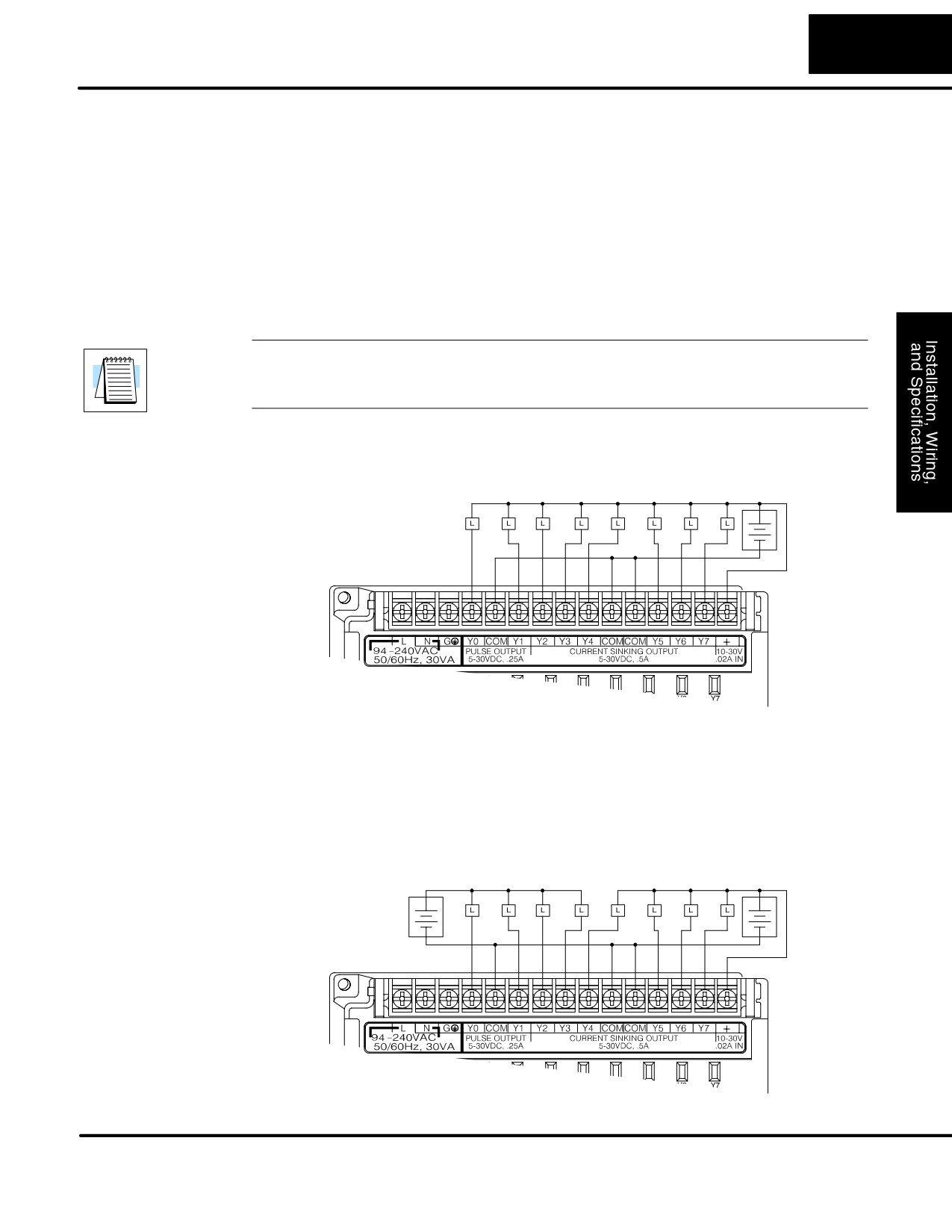
In the first and simplest example below, all commons are connected together and all
inputs are sinking.
+
-
In the next example, the first four inputs are sinking, and the last six are sourcing.
+
-
+
+12 VDC
External
-
Supply
In the last example, four inputs are sinking DC, four are sourcing DC, and two are
AC.
+
-
+12VDC
+24 VAC
External
+
-
External
Supply
Supply
DL105 PLC User Manual, 2nd Edition, Rev. A
2-25
Installation, Wiring, and Specifications
DC Output
DL105 DC output circuits are high-performance MOSFET switches with low
Wiring Methods
on-resistance and fast switching times. Please note the following characteristics
which are unique to the DC output type:
S There is only one electrical common for all eight outputs, even though
there are three common terminals. All eight outputs belong to one bank.
S The output switches are current-sinking only. However, you can still use
different DC voltages from one load to another.
S The output circuit inside the PLC requires external power. The supply
(-) must be connected to a common terminal, and the supply (+)
connects the the right-most terminal on the upper connector.
NOTE: Always connect all three common terminals together at the connector with
short wires (do not leave some common terminals unconnected).This provides
three connections to share the load return current, enhancing reliability.
In the example below, all eight outputs share a common supply. It may be external as
shown, or they may use the auxiliary +24VDC supply when available.
Output Point Wiring
+
+24 VDC
External
-
Supply
In the next example below, the outputs have “split” supplies. The first four outputs are
using a +5 VDC supply, and the last four are using a +24 VDC supply. However, you
can split the outputs among any number of supplies, as long as:
S all supply voltages are within the specified range
S all output points are wired as sinking
S all source (-) terminals are connected together
Output Point Wiring
+5 VDC
+
+
+24 VDC
External
External
-
–
Supply
Supply
DL105 PLC User Manual, 2nd Edition, Rev. A
2-26
Installation, Wiring, and Specifications
High-Speed I/O
DL105 versions with DC type input or output points contain a dedicated High-Speed
Wiring Methods
I/O circuit (HSIO). The circuit configuration is programmable, and it processes select
I/O points independently from the CPU scan. Chapter 4 discusses the programming
options for HSIO. While the HSIO circuit has six modes, we show wiring diagrams for
two of the most popular modes in this chapter. The high-speed input interfaces to
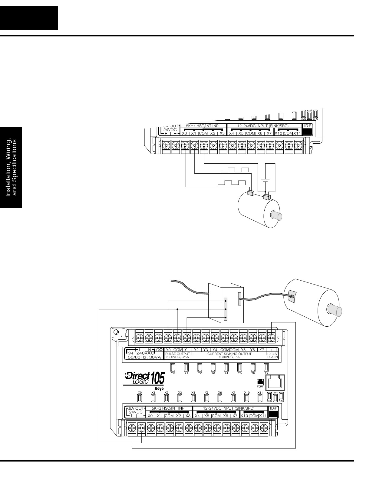
points X0 - X3. Properly configured, the DL105 can count quadrature pulses at up to
5 kHz from an incremental encoder as shown below.
Signal Common
Phase B
+
12 - 24 VDC
Phase A
-
Encoder Input Wiring
Encoder
DL105 versions with DC type output points can use the High Speed I/O Pulse Output
feature. It can generate high-speed pulses for specialized control such as stepper
motor / intelligent drive systems. Outputs Y0 and Y1 can generate pulse and
direction signals, or they can generate CCW and CW pulse signals respectively. See
Chapter 3 on high-speed input and pulse output options.
Power Input
Motor
Amplifier
Pulse Output Wiring
Pulse
Signal Common
Direction
DL105 PLC User Manual, 2nd Edition, Rev. A
2-27
Installation, Wiring, and Specifications
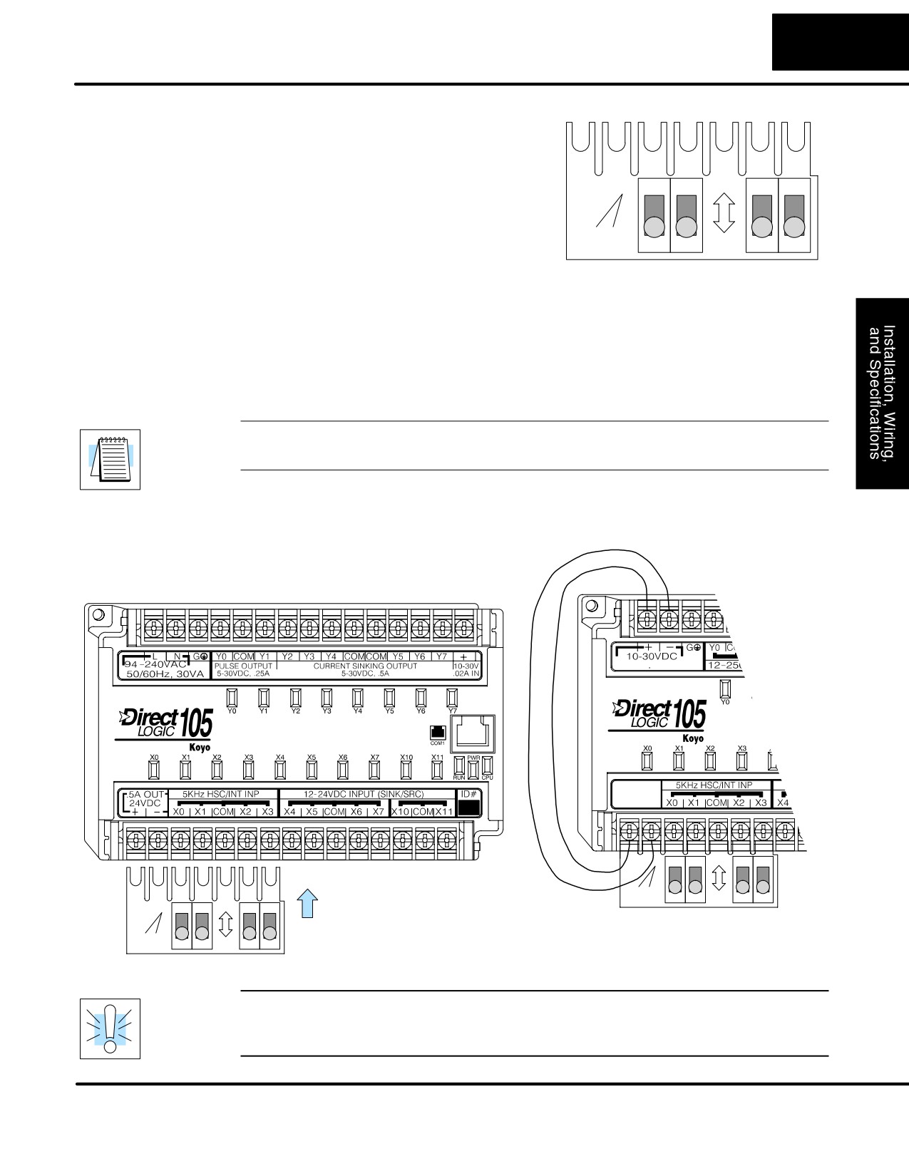
F1-04SIM Input
The F1-04SIM Input Simulator, shown to
Simulator Wiring
the right, provides four switches for inputs
X0 through X3. The simulator is useful
during program development or for debug
ON
purposes. It works by using the +24VDC
FACTS
auxiliary supply output, routing the voltage
engineering
through the switches and into the inputs.
F1-04SIM
OFF
In use, the simulator can quickly provide test inputs to your ladder program. The
status of outputs is observable on the front panel LEDs, even without wiring the
outputs to any loads.
The Simulator works on all DC input versions of the DL105. DC-powered versions
need two wires from the power input to connect to the two left-most terminals on the
simulator (wiring shown below), since DC-powered units do not generate +24VDC
auxiliary output. Polarity does not matter, since the inputs can be sinking or sourcing.
NOTE: The Input Simulator will not work on DL105 micros with AC type inputs. The
+24 VDC auxiliary supply voltage is less than the required input threshold.
F1-130DR/F1-130DR-CE, F1-130DD/F1-130DD-CE, F1-130DA
F1-130DR-D, F1-130DD-D only
(see warning below)
10W
ON
FACTS
engineering
Slide simulator under
F1-04SIM
OFF
leftĆmost terminals
ON
FACTS
and tighten screws.
engineering
F1-04SIM
OFF
NOTE: Never attempt to install more than one simulator on one DL105 PLC.
WARNING: DO NOT use the two wires as shown above on AC-powered DL105
PLCs. Doing so will permanently damage the Micro PLC and may result in electrical
shock due to the exposed circuit board of the input simulator.
DL105 PLC User Manual, 2nd Edition, Rev. A
2-28
Installation, Wiring, and Specifications
Wiring Diagrams and Specifications
The remainder of this chapter dedicates two to three pages to each of the eight
versions of DL105 Micro PLCs. Each section contains a basic wiring diagram,
equivalent I/O circuits, and specification tables. Please refer to the section which
describes the particular DL105 version used in your application.
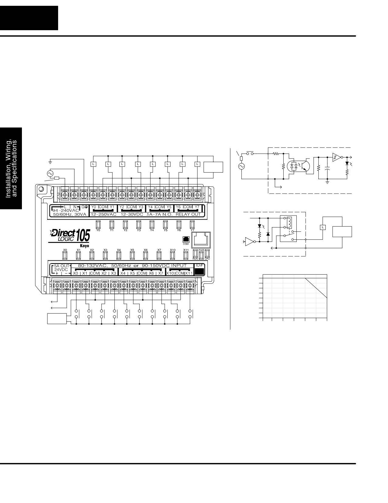
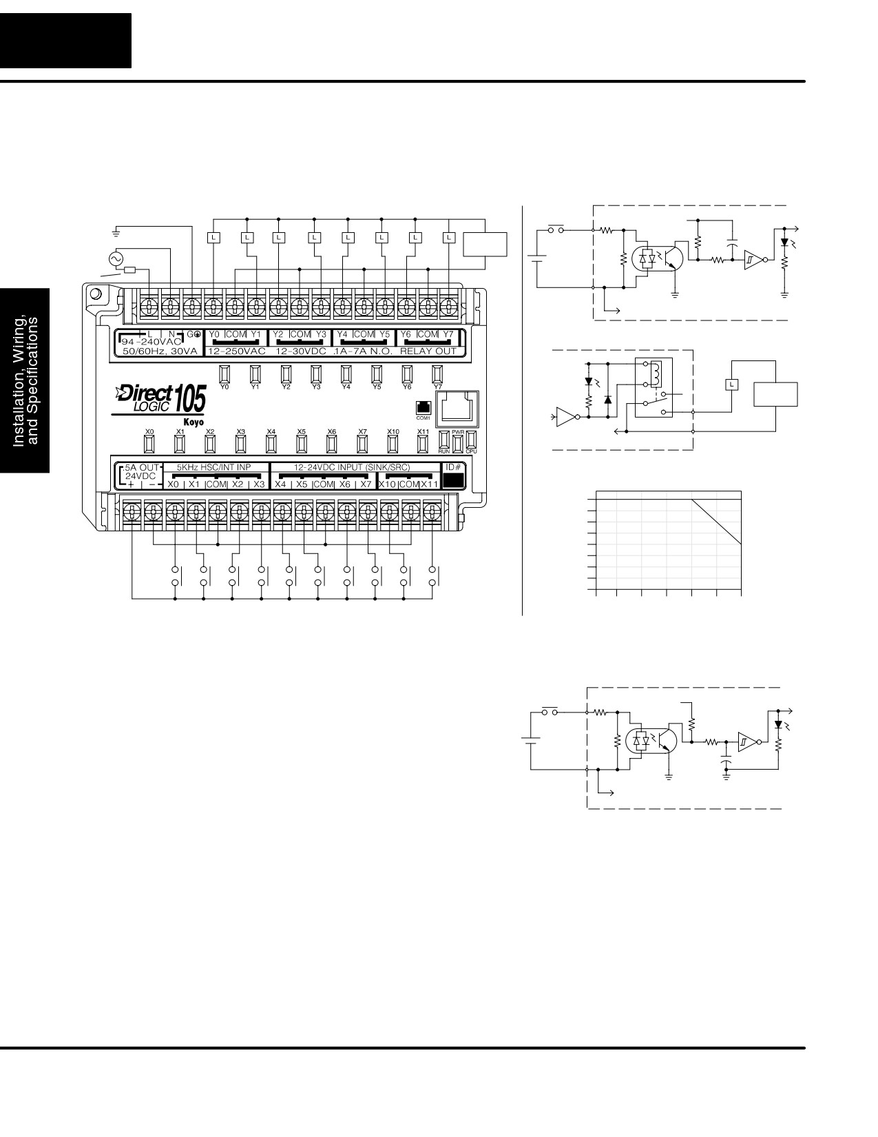
F1-130AR
The F1-130AR Micro PLC features ten AC inputs and eight relay contact outputs.
I/O Wiring Diagram
The following diagram shows a typical field wiring example. The AC external power
connection uses three terminals at the top left as shown.
Power
Fuse or
Equivalent Input Circuit
C.B.
Input Wiring
Output Point Wiring
Input
Optical
Ground
Isolator
+V
AC or DC
Neutral
Supply
Fuse
or
Line
Common
C.B.
To other circuits in bank
Equivalent Output Circuit
+V
AC or DC
Supply
Output
Common
To other circuits in bank
Derating Chart for Relay Outputs
Points
8
7A
6A
6
7A
4
+
to field
devices
-
2
AC or DC
0
Supply
0
10
20
30
40
50
60°C
32
50
68
86
104
122
140°F
Input Point Wiring
Ambient Temperature (°C/°F)
The ten AC input channels use terminals on the bottom connector. This input type
also works for high-voltage DC signals. Inputs are organized into two banks of four,
plus one bank of two. Each bank has a common terminal. In the case of DC input
signals, the input may be wired in as either the sourcing or sinking type. The wiring
example above shows all commons connected together, but separate supplies and
common circuits may be used. The equivalent input circuit shows one channel of a
typical bank.
The eight relay output channels use terminals on the top connector. Outputs are
organized into four banks of two normally-open relay contacts. Each bank has a
common terminal. The wiring example above shows all commons connected
together, but separate supplies and common circuits may be used. The equivalent
output circuit shows one channel of a typical bank. The relay contacts can switch AC
or DC voltages.
DL105 PLC User Manual, 2nd Edition, Rev. A
2-29
Installation, Wiring, and Specifications
Auxiliary +24V
The F1-130AR has a +24V supply output to power external devices. The output is
Power Supply
rated at 0.5 Amperes, and includes short-circuit protection and full isolation from
internal CPU circuitry. These features make it ideal for powering sensors, solenoids,
and other field devices. In fact, it can be used as the DC supply for loads in the relay
output circuits. Be sure the combined load currents do not exceed 0.5 A. Note that on
the F1-130AR, the +24V auxiliary output is not high enough to power its input
circuits (input ON threshold is 90VDC).
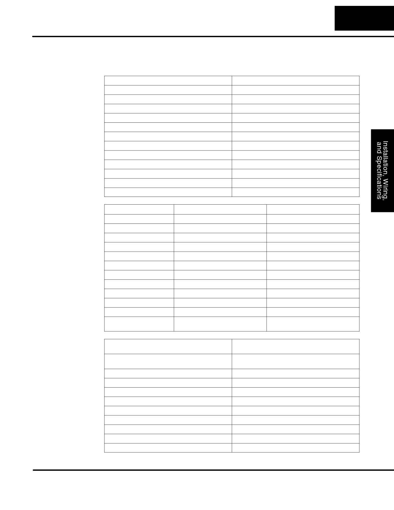
F1-130AR
External Power Requirements
100 - 240 +10% -15%
General
Communication Port
K-Sequence, 9600 baud, 8 data bits, odd parity
Specifications
Programming cable type
D2-DSCBL
Internal Field Supply Ratings
+24VDC , 0.5A maximum, isolated
Operating Temperature
32 to 140° F (0 to 60_ C)
Storage Temperature
-4 to 158° F (-20 to 70_ C)
Relative Humidity
5 to 95% (non-condensing)
Environmental air
No corrosive gases permitted
Vibration
MIL STD 810C 514.2
Shock
MIL STD 810C 516.2
Noise Immunity
NEMA ICS3-304
Terminal Type
Removable
Wire Gauge
One AWG14 or two AWG16, AWG24 minimum
AC Input
Input Voltage Range for ON condition
80 - 132 VAC, or 90 - 150 VDC
Specifications
Input Current
6 mA @ 132 VAC
X0 - X7, X10 - X11
6.8 mA @ 150 VDC
Maximum Voltage
132 VAC, or 150 VDC
ON Current/Voltage
>4 mA @ 80 VAC, or 90 VDC
OFF Current/Voltage
<2 mA @ 45 VAC, or 60 VDC
OFF to ON Response
< 8 mS
ON to OFF Response
<15 mS
Status Indicators
Logic Side
Commons
4 channels / common x 2 banks,
2 channels / common x 1 bank
Relay Output
Operating Voltage
12 - 250 VAC, 12 - 30 VDC @ 7A,
30 - 150 VDC @ 0.5A, resistive
Specifications
Y0 - Y7
Output Current
7A / point (subject to derating)
14A / common
Maximum Motor Load
1/3 HP
Maximum Voltage
265 VAC, 150 VDC
Minimum Off Resistance
100 meg ohms @ 500 VDC
Smallest Recommended Load
10 mA
OFF to ON Response
15 mS
ON to OFF Response
5 mS
Status Indicators
Logic Side
Commons
2 channels / common x 4 banks
Fuses
None (external recommended)
DL105 PLC User Manual, 2nd Edition, Rev. A
2-30
Installation, Wiring, and Specifications
F1-130DR/
These micro PLCs feature ten DC inputs and eight relay contact outputs. The
F1-130DR-CE
following diagram shows a typical field wiring example. The AC external power
I/O Wiring Diagram
connection uses three terminals at the top left as shown.
Equivalent Circuit,
Power
Output Point Wiring
Standard Inputs (X4 - X11)
Input Wiring
+V
Ground
Input
Optical
Isolator
AC or DC
Neutral
Supply
+
Fuse
Line
or
-
C.B.
Common
To other circuits in bank
Equivalent Output Circuit
+V
AC or DC
Supply
Output
Common
To other circuits in bank
Derating Chart for Relay Outputs
Points
8
7A
6A
6
+
-
4
7A
2
0
0
10
20
30
40
50
60°C
32
50
68
86
104
122
140°F
Input Point Wiring
Ambient Temperature (°C/°F)
The ten DC input channels use terminals
Equivalent Circuit, High-
on the bottom connector. Inputs are
Speed Inputs (X0 - X3)
organized into two banks of four, plus one
+V
Input
Optical
bank of two. Each bank has an isolated
Isolator
common terminal, and may be wired as
+
either sinking or sourcing inputs. The
-
wiring example above shows all commons
Common
connected together, but separate supplies
and common circuits may be used. The
To other circuits in bank
equivalent circuit for standard inputs is
shown above, and the high-speed input
circuit is shown to the right.
The eight output channels use terminals on the top connector. Outputs
are
organized into four banks of two normally-open relay contacts. Each bank has a
common terminal. The wiring example above shows all commons connected
together, but separate supplies and common circuits may be used. The equivalent
output circuit shows one channel of a typical bank. The relay contacts can switch AC
or DC voltages.
Auxiliary +24V
These versions have a +24V supply output to power external devices. The output is
Power Supply
rated at 0.5 Amperes, and includes short-circuit protection and full isolation from
internal CPU circuitry. These features make it ideal for powering sensors, solenoids,
DL105 PLC User Manual, 2nd Edition, Rev. A
2-31
Installation, Wiring, and Specifications
and other field devices. In fact, it can be used as the DC supply for switches or
sensors in the input circuit, or for loads in the relay output circuits. Be sure the
combined load currents do not exceed 0.5 A.
F1-130DR/
External Power Requirements
100 - 240 +10% -15%
F1-130DR-CE
Communication Port
K-Sequence, 9600 baud, 8 data bits, odd parity
General
Programming cable type
D2-DSCBL
Specifications
Internal Field Supply Ratings
+24VDC , 0.5A maximum, isolated
Operating Temperature
32 to 140° F (0 to 60_ C)
Storage Temperature
-4 to 158° F (-20 to 70_ C)
Relative Humidity
5 to 95% (non-condensing)
Environmental air
No corrosive gases permitted
Vibration
MIL STD 810C 514.2
Shock
MIL STD 810C 516.2
Noise Immunity
NEMA ICS3-304
Terminal Type
Removable
Wire Gauge
One AWG14 or two AWG16, AWG24 minimum
DC Input
Parameter
High-Speed Inputs, X0 - X3
Standard DC Inputs X4 - X11
Specifications
Input Voltage Range
10 - 26.4 VDC
10 - 26.4 VDC or 21.6 - 26.4 VAC
Maximum Voltage
30 VDC (5 kHz maximum frequency)
30 VDC
Minimum Pulse Width
100 ms
N/A
ON Voltage Level
> 9.0 VDC
> 9.0 VDC
OFF Voltage Level
< 2.0 VDC
< 2.0 VDC
Input Impedance
2.8 kW @ 12 - 24 VDC
2.8 kW @ 12 - 24 VDC
Minimum ON Current
>3 mA
>3 mA
Maximum OFF Current
< 0.5 mA
<0.5 mA
OFF to ON Response
<50 ms
2 - 8 mS, 4 mS typical
ON to OFF Response
< 50 ms
2 - 8 mS, 4 mS typical
Status Indicators
Logic side
Logic side
Commons
4 channels / common x 1 bank
4 channels / common x 1 bank,
2 channels / common x 1 bank
Relay Output
Operating Voltage
12 - 250 VAC, 12 - 30 VDC @ 7A,
30 - 150 VDC @ 0.5A, resistive
Specifications
Output Current
7A / point (subject to derating)
14A / common
Maximum Motor Load
1/3 HP
Maximum Voltage
265 VAC, 30 VDC
Minimum Off Resistance
100 meg ohms @ 500 VDC
Smallest Recommended Load
10 mA
OFF to ON Response
15 mS
ON to OFF Response
5 mS
Status Indicators
Logic Side
Commons
2 channels / common x 4 banks
Fuses
None (external recommended)
DL105 PLC User Manual, 2nd Edition, Rev. A
2-32
Installation, Wiring, and Specifications
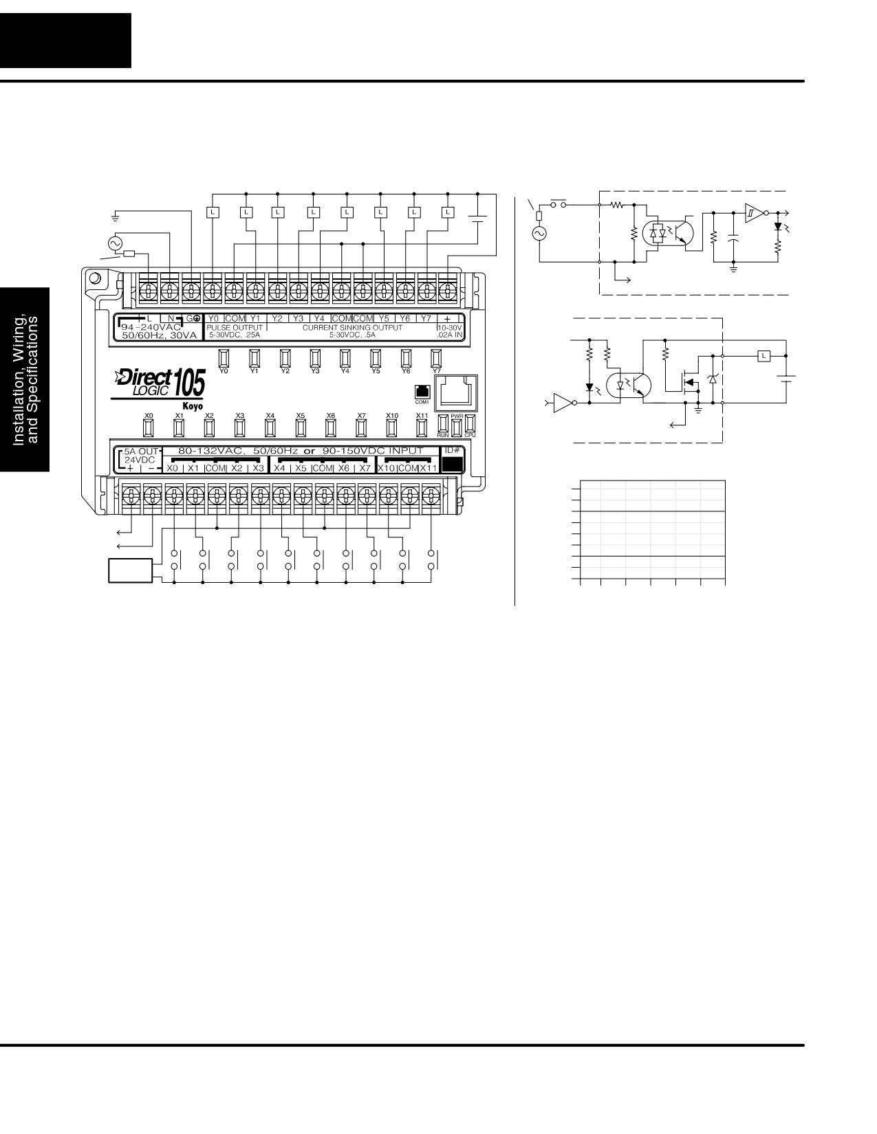
F1-130AD
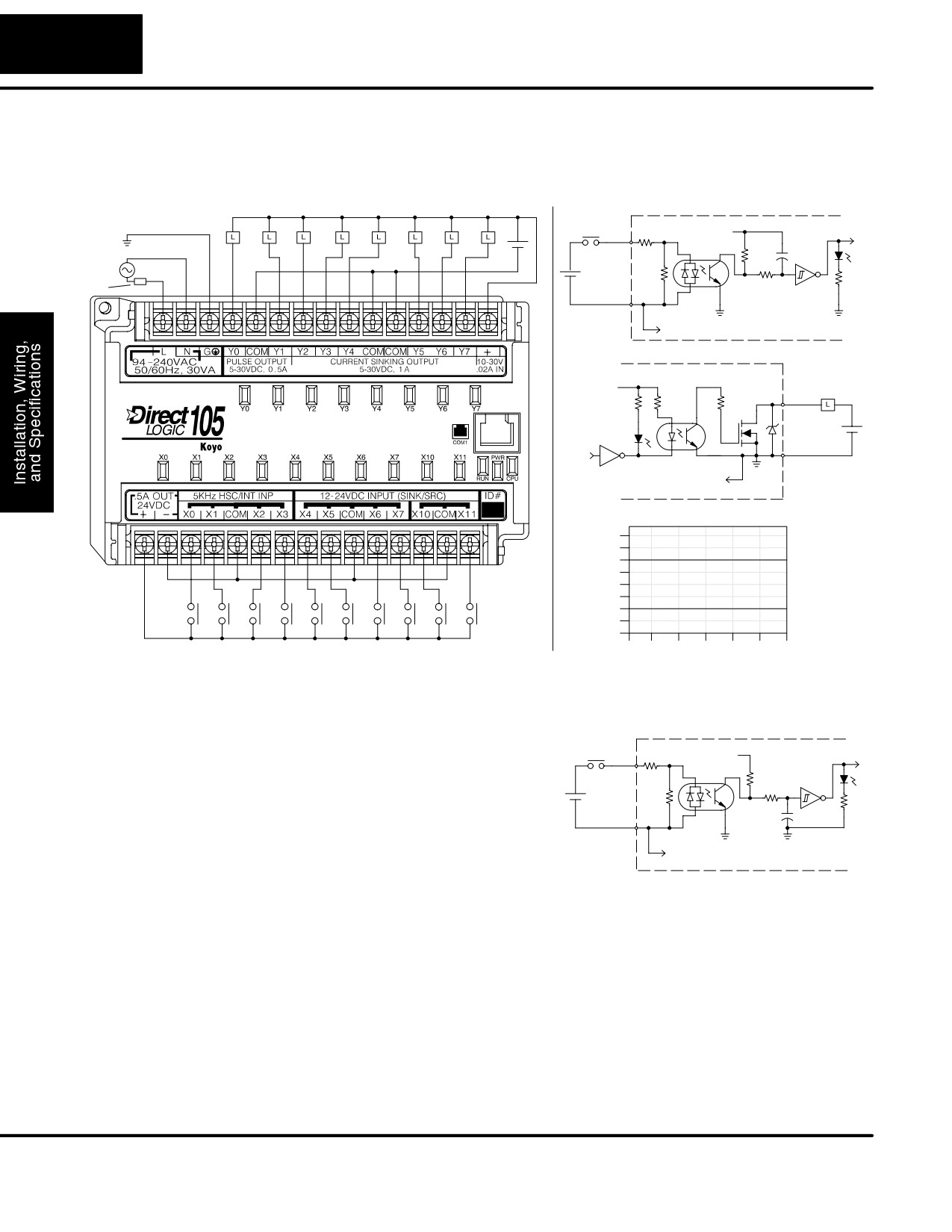
The F1-130AD Micro PLC features ten AC inputs and eight DC outputs. The
I/O Wiring Diagram
following diagram shows a typical field wiring example. The AC external power
connection uses three terminals at the top left as shown.
Power
Output Point Wiring
Fuse or
Equivalent Input Circuit
Input Wiring
12 - 24 VDC
C.B.
Input
Optical
Ground
+
Isolator
+V
Neutral
-
Fuse
or
Line
C.B.
Common
To other circuits in bank
Equivalent Output Circuit
+V
+V
Output
+
-
Common
To all other output circuits
Derating Chart for DC Outputs
Points
8
0.6A (8
ckts), 1.0A (4 ckts)
6
Y2 - Y7
+
to field
4
devices
-
0.3A (8
ckts), 0.5A (4 ckts)
2
Y0 - Y1
AC or DC
Supply
0
0
10
20
30
40
50
60°C
Input Point Wiring
32
50
68
86
104
122
140°F
Ambient Temperature (°C/°F)
The ten AC input channels use terminals on the bottom connector. This input type
also works for high-voltage DC signals. Inputs are organized into two banks of four,
plus one bank of two. Each bank has an isolated common terminal. In the case of DC
input signals, the input may be wired in as either the sourcing or sinking type. The
wiring example above shows all commons connected together, but separate
supplies and common circuits may be used. The equivalent input circuit shows one
channel of a typical bank.
The eight current sinking DC output channels use terminals on the top connector.
The three common terminals are internally connected, meaning all outputs actually
share the same electrical common. The wiring example above shows all commons
connected together, because it is best to share the common current among the three
terminal connections. Note the requirement for external power on the end
(right-most) terminal. The equivalent output circuit shows one channel of the bank of
eight.
Auxiliary +24V
The F1-130AD has a +24V supply output to power external devices. The output is
Power Supply
rated at 0.5 Amperes, and includes short-circuit protection and full isolation from
internal CPU circuitry. These features make it ideal for powering sensors, solenoids,
and other field devices. In fact, it can be used as the supply for loads in the DC output
circuits. Since the outputs are the sinking type, you’ll need to connect +24V to the
output commons. Be sure the combined load currents do not exceed 0.5 A. Note that
on the F1-130AD, the +24V auxiliary output is not high enough to power its input
circuits (input ON threshold is 90VDC).
DL105 PLC User Manual, 2nd Edition, Rev. A
2-33
Installation, Wiring, and Specifications
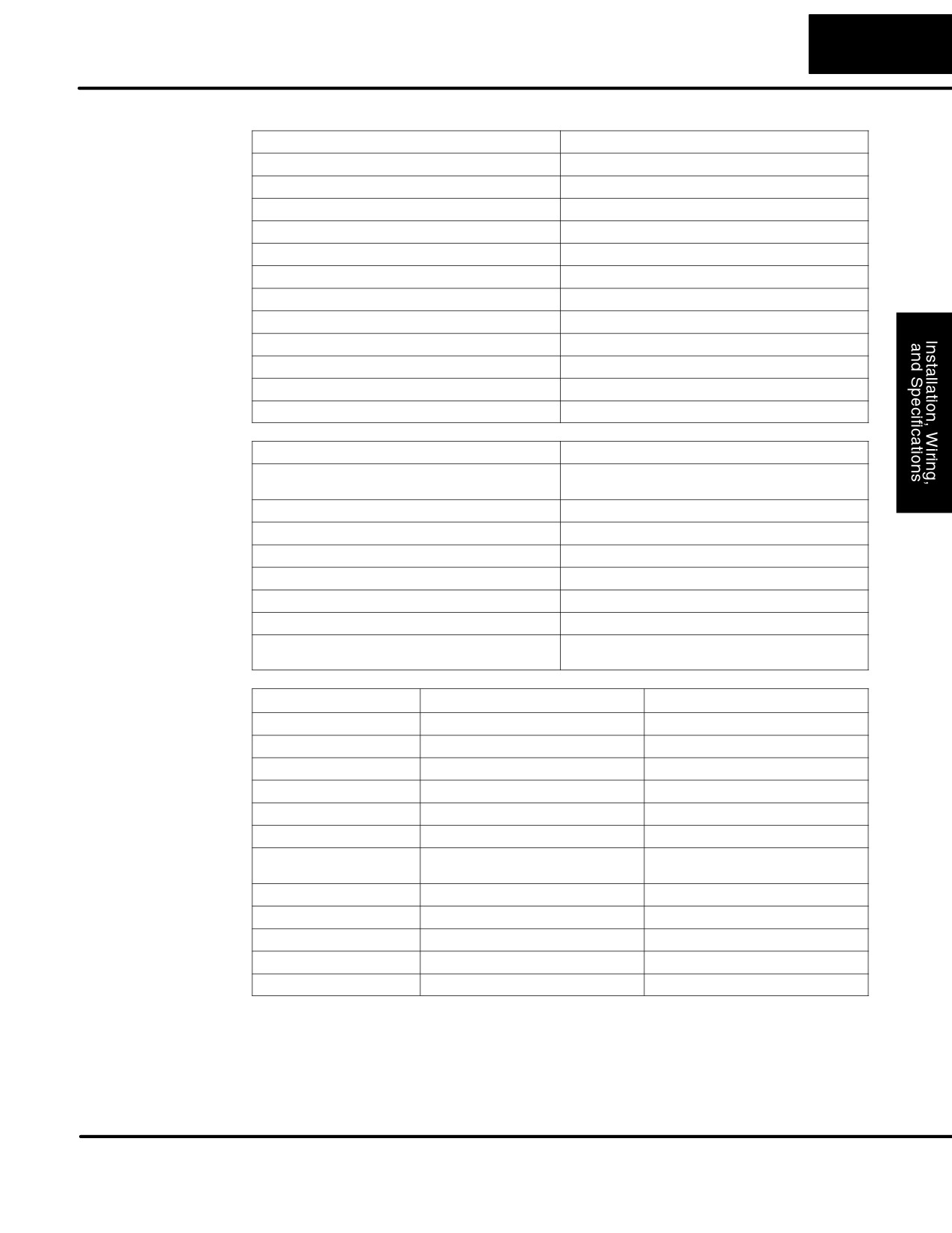
F1-130AD
External Power Requirements
100 - 240 + 10% -15%
General
Communication Port
K-Sequence, 9600 baud, 8 data bits, odd parity
Specifications
Programming cable type
D2-DSCBL
Internal Field Supply Ratings
+24VDC , 0.5A maximum, isolated
Operating Temperature
32 to 140° F (0 to 60_ C)
Storage Temperature
-4 to 158° F (-20 to 70_ C)
Relative Humidity
5 to 95% (non-condensing)
Environmental air
No corrosive gases permitted
Vibration
MIL STD 810C 514.2
Shock
MIL STD 810C 516.2
Noise Immunity
NEMA ICS3-304
Terminal Type
Removable
Wire Gauge
One AWG14 or two AWG16, AWG24 minimum
AC Input
Input Voltage Range for ON condition
80 - 132 VAC, or 90 - 150 VDC
Specifications
Input Current
6 mA @ 132 VAC
6.8 mA @ 150 VDC
Maximum Voltage
132 VAC, or 150 VDC
ON Current/Voltage
>4 mA @ 80 VAC, or 90 VDC
OFF Current/Voltage
<2 mA @ 45 VAC, or 60 VDC
OFF to ON Response
< 8 mS
ON to OFF Response
<15 mS
Status Indicators
Logic Side
Commons
4 channels / common x 2 banks,
2 channels / common x 1 bank
DC Output
Parameter
Pulse Outputs, Y0 - Y1
Standard Outputs, Y2 - Y7
Specifications
Operating Voltage
5 - 30 VDC
5 - 30 VDC
Peak Voltage
60 VDC (7 kHz maximum frequency)
60 VDC
On Voltage Drop
0.4 VDC @ 0.25A
0.4 VDC @ 0.5A
Max Current (resistive)
0.5 A / point (subject to derating)
1.0 A / point (subject to derating)
Max leakage current
15 mA @ 30 VDC
15 mA @ 30 VDC
Max inrush current
1.5 A for 10 mS, 0.5 A for 100 mS
3 A for 10 mS, 1 A for 100 mS
Extenal DC power required
10 - 30 VDC @30 mA,
10 - 30 VDC @30 mA,
plus load current
plus load current
OFF to ON Response
<10 mS
3.5 mS
ON to OFF Response
<70 mS
110 mS
Status Indicators
Logic Side
Logic Side
Commons
Internally connected
Internally connected
Fuses
None
None
DL105 PLC User Manual, 2nd Edition, Rev. A
2-34
Installation, Wiring, and Specifications
F1-130DD/
These micro PLCs feature ten DC inputs and eight DC outputs. The following
F1-130DD-CE
diagram shows a typical field wiring example. The AC external power connection
I/O Wiring Diagram
uses three terminals at the top left as shown.
Equivalent Circuit,
Power
Output Point Wiring
12 - 24 VDC
Standard Inputs (X4 - X11)
Input Wiring
+V
Ground
+
Input
Optical
Isolator
Neutral
-
+
Fuse
or
Line
C.B.
-
Common
To other circuits in bank
Equivalent Output Circuit
+V
+V
Output
+
-
Common
To all other output circuits
Derating Chart for DC Outputs
Points
8
0.6A (8
ckts), 1.0A (4
ckts)
6
Y2 - Y7
+
-
4
0.3A (8
ckts), 0.5A (4 ckts)
2
Y0 - Y1
0
0
10
20
30
40
50
60°C
Input Point Wiring
32
50
68
86
104
122
140°F
Ambient Temperature (°C/°F)
The ten DC input channels use terminals
Equivalent Circuit, High-
on the bottom connector. Inputs are
Speed Inputs (X0 - X3)
organized into two banks of four, plus one
+V
Input
Optical
bank of two. Each bank has an isolated
Isolator
common terminal, and may be wired as
+
either sinking or sourcing inputs. The
-
wiring example above shows all commons
Common
connected together, but separate supplies
and common circuits may be used. The
To other circuits in bank
equivalent circuit for standard inputs is
shown above, and the high-speed input
circuit is shown to the right.
The eight current sinking DC output channels use terminals on the top connector.
Outputs are organized as one bank of sinking outputs. The three common terminals
are internally connected, so all outputs actually share the same electrical common.
The wiring example above shows all commons connected together, because it is
best to share the common current among the three terminal connections. The
equivalent output circuit shows one channel of the bank of eight.
Auxiliary +24V
These versions have a +24V supply output to power external devices. The output is
Power Supply
rated at 0.5 Amperes, and includes short-circuit protection and full isolation from
internal circuitry. These features make it ideal for powering sensors, solenoids, and
DL105 PLC User Manual, 2nd Edition, Rev. A
2-35
Installation, Wiring, and Specifications
other field devices. In fact, it can be used as the DC supply for switches or sensors in
the input circuit, or for loads in the DC output circuits (up to 0.5 A).
F1-130DD/
External Power Requirements
100 - 240 +10% -15%
F130-DD-CE
Communication Port
K-Sequence, 9600 baud, 8 data bits, odd parity
General
Programming cable type
D2-DSCBL
Specifications
Internal Field Supply Ratings
+24VDC , 0.5A maximum, isolated
Operating Temperature
32 to 140° F (0 to 60_ C)
Storage Temperature
-4 to 158° F (-20 to 70_ C)
Relative Humidity
5 to 95% (non-condensing)
Environmental air
No corrosive gases permitted
Vibration
MIL STD 810C 514.2
Shock
MIL STD 810C 516.2
Noise Immunity
NEMA ICS3-304
Terminal Type
Removable
Wire Gauge
One AWG14 or two AWG16, AWG24 minimum
DC Input
Parameter
High-Speed Inputs, X0 - X3
Standard DC Inputs X4 - X11
Specifications
Input Voltage Range
10 - 26.4 VDC
10 - 26.4 VDC or 21.6 - 26.4 VAC
Maximum Voltage
30 VDC (5 kHz maximum frequency)
30 VDC
Minimum Pulse Width
100 ms
N/A
ON Voltage Level
> 9.0 VDC
> 9.0 VDC
OFF Voltage Level
< 2.0 VDC
< 2.0 VDC
Input Impedance
2.8 kW @ 12 - 24 VDC
2.8 kW @ 12 - 24 VDC
Minimum ON Current
>3 mA
>3 mA
Maximum OFF Current
< 0.5 mA
<0.5 mA
OFF to ON Response
<50 mS
2 - 8 mS, 4 mS typical
ON to OFF Response
< 50 mS
2 - 8 mS, 4 mS typical
Status Indicators
Logic side
Logic side
Commons
4 channels / common x 1 bank
4 channels / common x 1 bank,
2 channels / common x 1 bank
DC Output
Parameter
Pulse Outputs, Y0 - Y1
Standard Outputs, Y2 - Y7
Specifications
Operating Voltage
5 - 30 VDC
5 - 30 VDC
Peak Voltage
60 VDC (7 kHz maximum frequency)
60 VDC
On Voltage Drop
0.4 VDC @ 0.25A
0.4 VDC @ 0.5A
Max Current (resistive)
0.5 A / point (subject to derating)
1.0 A / point (subject to derating)
Max leakage current
15 mA @ 30 VDC
15 mA @ 30 VDC
Max inrush current
1.5 A for 10 mS, 0.5 A for 100 mS
3 A for 10 mS, 1 A for 100 mS
External DC power required
10 - 30 VDC @30 mA,
10 - 30 VDC @30 mA,
plus load current
plus load current
OFF to ON Response
<10 ms
3.5 ms
ON to OFF Response
<70 ms
110 ms
Status Indicators
Logic Side
Logic Side
Commons
Internally connected
Internally connected
Fuses
None
None
DL105 PLC User Manual, 2nd Edition, Rev. A
2-36
Installation, Wiring, and Specifications
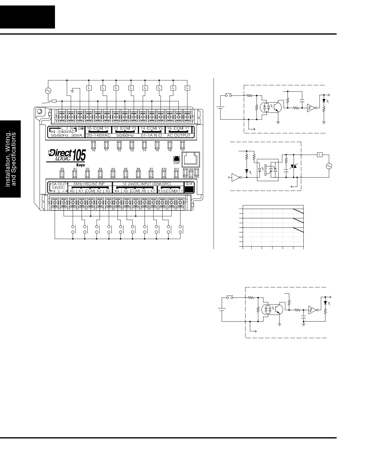
F1-130AA
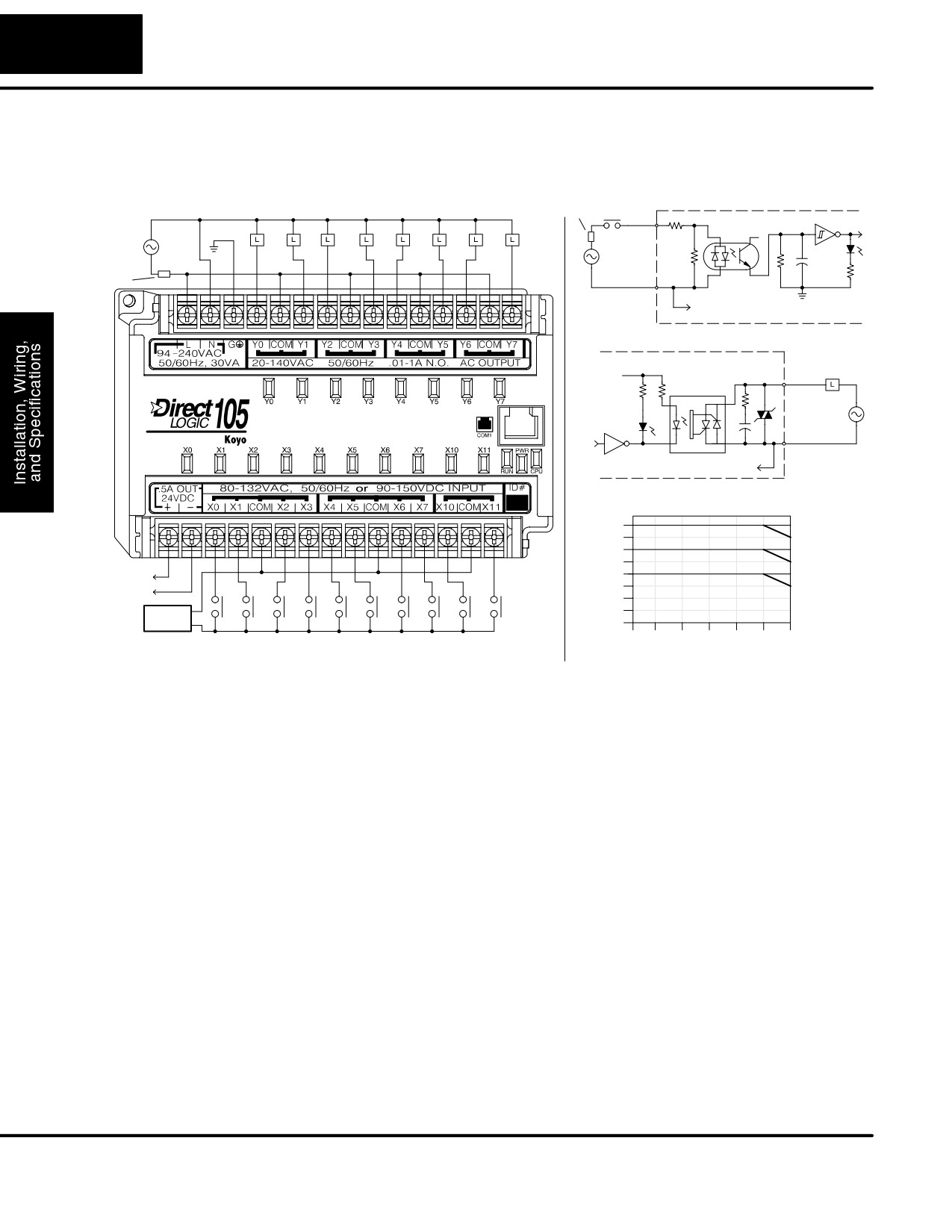
The F1-130AA Micro PLC features ten AC inputs and eight AC outputs. The
I/O Wiring Diagram
following diagram shows a typical field wiring example. The AC external power
connection uses three terminals at the top left as shown.
Power
Fuse or
Equivalent Input Circuit
Input Wiring
Output Point Wiring
C.B.
Input
Optical
Neutral
Isolator
+V
Ground
Fuse
Line
or
C.B.
Common
To other circuits in bank
Equivalent Output Circuit
+V
Optical
Output
Isolator/Triac
Common
To other circuit in bank
Derating Chart for AC Outputs
Points
8
1.2A
1.3A
1.3A
6
1.4A
1.5A
1.5A
+
4
1.6A
to field devices
-
1.7A
1.7A
2
AC or DC
Supply
0
0
10
20
30
40
50
60°C
Input Point Wiring
32
50
68
86
104
122
140°F
Ambient Temperature (°C/°F)
The ten AC input channels use terminals on the bottom connector. This input type
also works for high-voltage DC signals. Inputs are organized into two banks of four,
plus one bank of two. Each bank has an isolated common terminal. In the case of DC
input signals, the input may be wired in as either the sourcing or sinking type. The
wiring example above shows all commons connected together, but separate
supplies and common circuits may be used. The equivalent input circuit shows one
channel of a typical bank.
The eight output channels use terminals on the top connector. Outputs are
organized into four banks of two triac switches. Each bank has a common terminal.
The wiring example above shows all commons connected together, but separate
supplies and common circuits may be used. The equivalent output circuit shows one
channel of a typical bank.
Auxiliary +24V
The F1-130AA has a +24V supply output to power external devices. The output is
Power Supply
rated at 0.5 Amperes, and includes short-circuit protection and full isolation from
internal CPU circuitry. These features make it ideal for powering sensors, solenoids,
and other field devices. Note that on the F1-130AA, the +24V auxiliary output cannot
directly power its input and output circuits(input ON threshold is 90VDC, outputs
require AC only).
DL105 PLC User Manual, 2nd Edition, Rev. A
2-37
Installation, Wiring, and Specifications
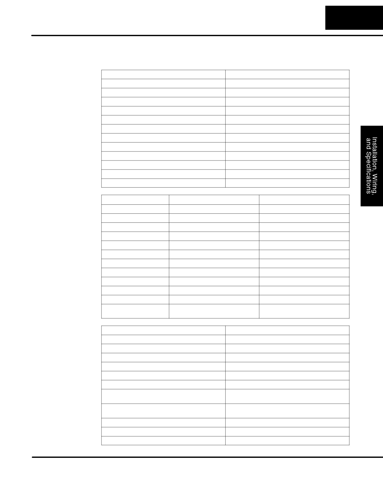
F1-130AA
External Power Requirements
100 - 240 +10% -15%
General
Communication Port
K-Sequence, 9600 baud, 8 data bits, odd parity
Specifications
Programming cable type
D2-DSCBL
Internal Field Supply Ratings
+24VDC , 0.5A maximum, isolated
Operating Temperature
32 to 140° F (0 to 60_ C)
Storage Temperature
-4 to 158° F (-20 to 70_ C)
Relative Humidity
5 to 95% (non-condensing)
Environmental air
No corrosive gases permitted
Vibration
MIL STD 810C 514.2
Shock
MIL STD 810C 516.2
Noise Immunity
NEMA ICS3-304
Terminal Type
Removable
Wire Gauge
One AWG14 or two AWG16, AWG24 minimum
AC Input
Input Voltage Range for ON condition
80 - 132 VAC, or 90 - 150 VDC
Specifications
Input Current
6 mA @ 132 VAC
6.8 mA @ 150 VDC
Maximum Voltage
132 VAC, or 150 VDC
ON Current/Voltage
>4 mA @ 80 VAC, or 90 VDC
OFF Current/Voltage
<2 mA @ 45 VAC, or 60 VDC
OFF to ON Response
< 8 mS
ON to OFF Response
<15 mS
Status Indicators
Logic Side
Commons
4 channels / common x 2 banks,
2 channels / common x 1 bank
AC Output
Operating Voltage
20 - 140 VAC, 47 - 63 Hz
Specifications
Peak Voltage
400 VAC
On Voltage Drop
1.3 VAC @ 2 A
Max Current
1.7 A / point, subject to derating
Max leakage current
1 mA @ 400 VAC
Max inrush current
30 A for 10 mS, 15 A for 100 mS
Minimum Load
10 mA
OFF to ON Response
8.33 mS @ 60 Hz, zero-crossing,
10 mS @ 50 Hz, zero-crossing
ON to OFF Response
8.33 mS @ 60 Hz, zero-crossing,
10 mS @ 50 Hz, zero-crossing
Status Indicators
Logic Side
Commons
2 channels / common x 4 banks
Fuses
None (external recommended)
DL105 PLC User Manual, 2nd Edition, Rev. A
2-38
Installation, Wiring, and Specifications
F1-130DA
The F1-130DA Micro PLC features ten DC inputs and eight AC outputs. The
following diagram shows a typical field wiring example. The AC external power
I/O Wiring Diagram
connection uses three terminals at the top left as shown.
Output Point Wiring
Equivalent Circuit,
Neutral
Standard Inputs (X4 - X11)
Ground
+V
Input
Optical
Fuse
Line
Isolator
or
C.B.
+
-
Common
To other circuits in bank
Equivalent Output Circuit
+V
Optical
Output
Isolator/Triac
Common
To other circuit in bank
Derating Chart for AC Outputs
Points
8
1.2A
+
-
1.3A
1.3A
6
1.4A
1.5A
1.5A
4
1.6A
1.7A
1.7A
2
Input Point Wiring
0
0
10
20
30
40
50
60°C
32
50
68
86
104
122
140°F
Ambient Temperature (°C/°F)
The ten DC input channels use terminals
Equivalent Circuit, High-
on the bottom connector. Inputs are
Speed Inputs (X0 - X3)
organized into two banks of four, plus one
+V
Input
Optical
bank of two. Each bank has an isolated
Isolator
common terminal, and may be wired as
+
sinking or sourcing inputs. The wiring
-
example above shows all commons
Common
connected together, but separate supplies
and common circuits may be used. The
To other circuits in bank
equivalent circuit for standard inputs is
shown above, and the high-speed input
circuit is shown to the right.
The eight output channels use terminals on the top connector. Outputs
are
organized into four banks of two triac switches. Each bank has a common terminal.
The wiring example above shows all commons connected together, but separate
supplies and common circuits may be used. The equivalent output circuit shows one
channel of a typical bank.
Auxiliary +24V
The F1-130DA has a +24V supply output to power external devices. The output is
Power Supply
rated at 0.5 Amperes, and includes short-circuit protection and full isolation from
internal CPU circuitry. These features make it ideal for powering sensors, solenoids,
and other field devices. In fact, it can be used as the DC supply for switches or
DL105 PLC User Manual, 2nd Edition, Rev. A
2-39
Installation, Wiring, and Specifications
sensors in the input circuit. Note that on the F1-130DA, the +24V output cannot
power its output circuits, because they require AC voltages.
F1-130DA
External Power Requirements
100 - 240 +10% -15%
General
Communication Port
K-Sequence, 9600 baud, 8 data bits, odd parity
Specifications
Programming cable type
D2-DSCBL
Internal Field Supply Ratings
+24VDC , 0.5A maximum, isolated
Operating Temperature
32 to 140° F (0 to 60_ C)
Storage Temperature
-4 to 158° F (-20 to 70_ C)
Relative Humidity
5 to 95% (non-condensing)
Environmental air
No corrosive gases permitted
Vibration
MIL STD 810C 514.2
Shock
MIL STD 810C 516.2
Noise Immunity
NEMA ICS3-304
Terminal Type
Removable
Wire Gauge
One AWG14 or two AWG16, AWG24 minimum
DC Input
Parameter
High-Speed Inputs, X0 - X3
Standard DC Inputs X4 - X11
Specifications
Input Voltage Range
10 - 26.4 VDC
10 - 26.4 VDC or 21.6 - 26.4 VAC
Maximum Voltage
30 VDC (5 kHz maximum frequency)
30 VDC
Minimum Pulse Width
100 mS
N/A
ON Voltage Level
> 9.0 VDC
> 9.0 VDC
OFF Voltage Level
< 2.0 VDC
< 2.0 VDC
Input Impedance
2.8 kW @ 12 - 24 VDC
2.8 kW @ 12 - 24 VDC
Minimum ON Current
>3 mA
>3 mA
Maximum OFF Current
< 0.5 mA
<0.5 mA
OFF to ON Response
<50 mS
2 - 8 mS, 4 mS typical
ON to OFF Response
< 50 mS
2 - 8 mS, 4 mS typical
Status Indicators
Logic side
Logic side
Commons
4 channels / common x 1 bank
4 channels / common x 1 bank,
2 channels / common x 1 bank
AC Output
Operating Voltage
20 - 140 VAC, 47 - 63 Hz
Specifications
Peak Voltage
400 VAC
On Voltage Drop
1.3 VAC @ 2 A
Max Current
1.7 A / point, subject to derating
Max leakage current
1 mA @ 400 VAC
Max inrush current
30 A for 10 mS, 15 A for 100 mS
Minimum Load
10 mA
OFF to ON Response
8.33 mS @ 60 Hz, zero-crossing,
10 mS @ 50 Hz, zero-crossing
ON to OFF Response
8.33 mS @ 60 Hz, zero-crossing,
10 mS @ 50 Hz, zero-crossing
Status Indicators
Logic Side
Commons
2 channels / common x 4 banks
Fuses
None (external recommended)
DL105 PLC User Manual, 2nd Edition, Rev. A
2-40
Installation, Wiring, and Specifications
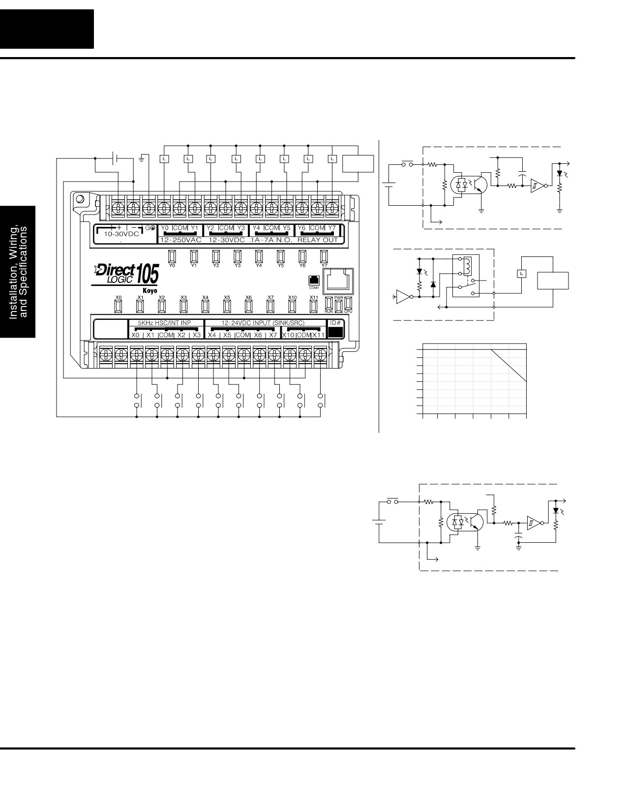
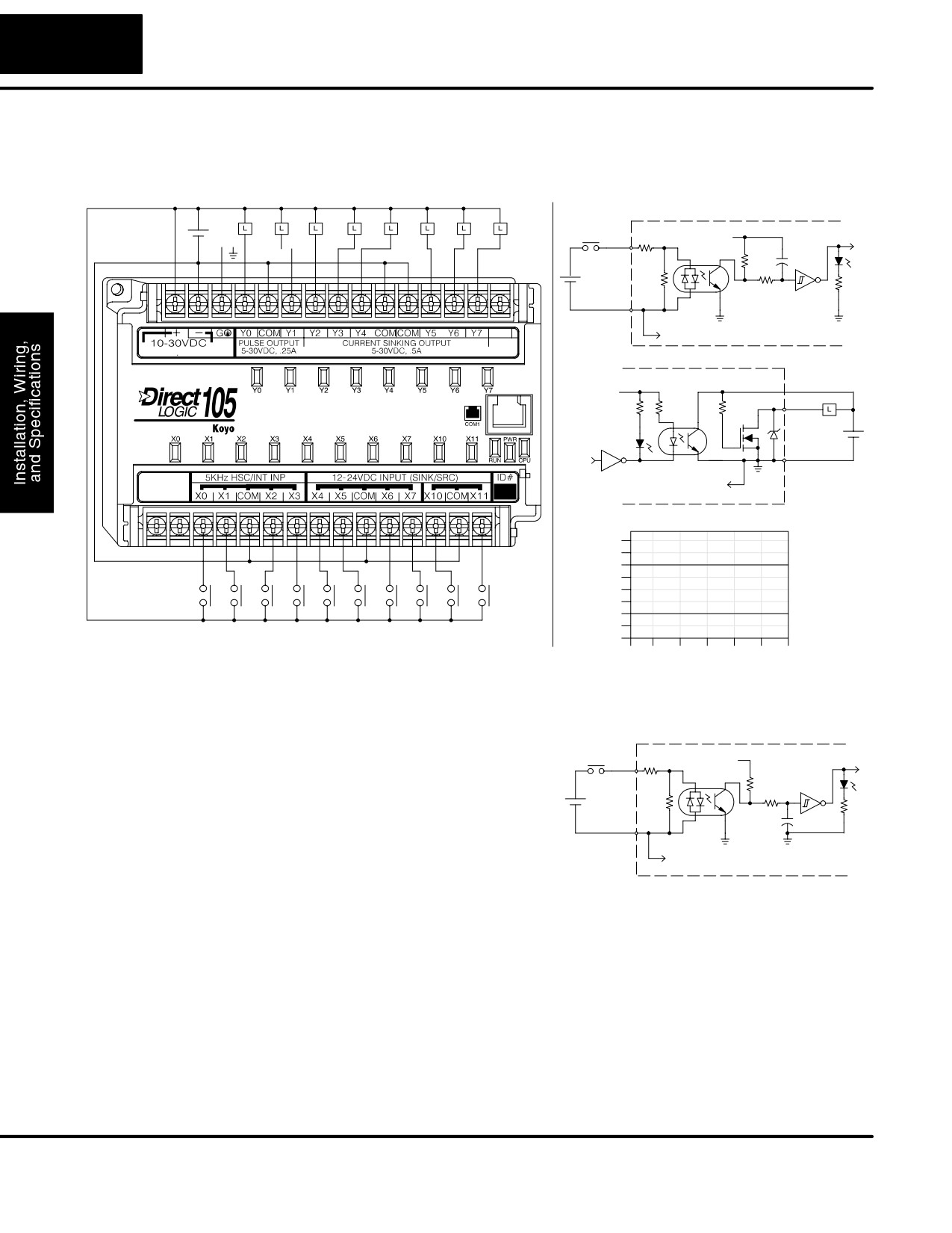
F1-130DR-D
The F1-130DR-D Micro PLC features ten DC inputs and eight relay outputs. The
I/O Wiring Diagram
following diagram shows a typical field wiring example. The DC external power
connection uses three terminals at the top left as shown.
Equivalent Circuit,
Power Input Wiring
Output Point Wiring
Standard Inputs (X4 - X11)
10 - 30VDC
Ground
+V
Input
AC or DC
Optical
+
-
Supply
Isolator
+
-
Common
To other circuits in bank
10W
Equivalent Output Circuit
+V
AC or DC
Supply
Output
Common
To other circuits in bank
Derating Chart for Relay Outputs
Points
8
7A
6A
6
7A
4
2
+
0
0
10
20
30
40
50
60°C
Input Point Wiring
32
50
68
86
104
122
140°F
Ambient Temperature (°C/°F)
The ten DC input channels use terminals
Equivalent Circuit, High-
on the bottom connector. Inputs are
Speed Inputs (X0 - X3)
organized into two banks of four, plus one
+V
Input
Optical
bank of two. Each bank has an isolated
Isolator
common terminal, and may be wired as
+
sinking or sourcing inputs. The wiring
-
example above shows all commons
Common
connected together, but separate supplies
and common circuits may be used. The
To other circuits in bank
equivalent circuit for standard inputs is
shown above, and the high-speed input
circuit is shown to the right.
The eight output channels use terminals on the top connector. Outputs
are
organized into four banks of two normally-open relay contacts. Each bank has a
common terminal. The wiring example above shows all commons connected
together, but separate supplies and common circuits may be used. The equivalent
output circuit shows one channel of a typical bank. The relay contacts can switch AC
or DC voltages.
No Auxiliary +24V
The F1-130DR-D does not include a +24V output, as do most other DL105 PLCs.
Power Supply
Since this unit requires +24V as the main supply input, it it usually most economical
to use the same supply to power suitable field devices. In the wiring diagram above,
DL105 PLC User Manual, 2nd Edition, Rev. A
2-41
Installation, Wiring, and Specifications
the external power source for the unit also powers the input circuitry. The same
external supply can power both input and output circuits, because they are both
isolated from the internal logic circuitry.
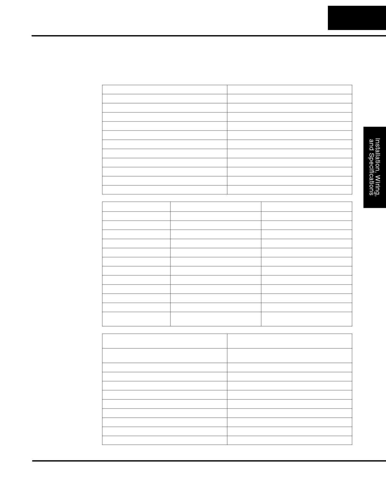
F1-130DR-D
External Power Requirements
10-30VDC, 1.5A
General
Communication Port
K-Sequence, 9600 baud, 8 data bits, odd parity
Specifications
Programming cable type
D2-DSCBL
Operating Temperature
32 to 140° F (0 to 60_ C)
Storage Temperature
-4 to 158° F (-20 to 70_ C)
Relative Humidity
5 to 95% (non-condensing)
Environmental air
No corrosive gases permitted
Vibration
MIL STD 810C 514.2
Shock
MIL STD 810C 516.2
Noise Immunity
NEMA ICS3-304
Terminal Type
Removable
Wire Gauge
One AWG14 or two AWG16, AWG24 minimum
DC Input
Parameter
High-Speed Inputs, X0 - X3
Standard DC Inputs X4 - X11
Specifications
Input Voltage Range
10 - 26.4 VDC
10 - 26.4 VDC or 21.6 - 26.4 VAC
Maximum Voltage
30 VDC (5 kHz maximum frequency)
30 VDC
Minimum Pulse Width
100 ms
N/A
ON Voltage Level
> 9.0 VDC
> 9.0 VDC
OFF Voltage Level
< 2.0 VDC
< 2.0 VDC
Input Impedance
2.8 kW @ 12 - 24 VDC
2.8 kW @ 12 - 24 VDC
Minimum ON Current
>3 mA
>3 mA
Maximum OFF Current
< 0.5 mA
<0.5 mA
OFF to ON Response
<50 mS
2 - 8 mS, 4 mS typical
ON to OFF Response
< 50 mS
2 - 8 mS, 4 mS typical
Status Indicators
Logic side
Logic side
Commons
4 channels / common x 1 bank
4 channels / common x 1 bank,
2 channels / common x 1 bank
Relay Output
Operating Voltage
12 - 250 VAC, 12 - 30 VDC @ 7A,
30 - 150 VDC @ 0.5A, resistive
Specifications
Output Current
7A / point (subject to derating)
14A / common
Maximum Motor Load
1/3 HP
Maximum Voltage
265 VAC, 150 VDC
Minimum Off Resistance
100 meg ohms @ 500 VDC
Smallest Recommended Load
10 mA
OFF to ON Response
15 ms
ON to OFF Response
5 ms
Status Indicators
Logic Side
Commons
2 channels / common x 4 banks
Fuses
None (external recommended)
DL105 PLC User Manual, 2nd Edition, Rev. A
2-42
Installation, Wiring, and Specifications
F1-130DD-D
The F1-130DD-D Micro PLC features ten DC inputs and eight DC outputs. The
I/O Wiring Diagram
following diagram shows a typical field wiring example. The DC external power
connection uses three terminals at the top left as shown.
Power Input Wiring
Output Point Wiring
Equivalent Circuit,
Standard Inputs (X4 - X11)
+
+V
10 - 30VDC
-
Ground
Input
Optical
Isolator
+
-
Common
To other circuits in bank
10W
Equivalent Output Circuit
+V
+V
Output
+
-
Common
To all other output circuits
Derating Chart for DC Outputs
Points
8
-
0.6A (8
ckts), 1.0A (4 ckts)
6
Y2 - Y7
4
0.3A (8 ckts), 0.5A (4 ckts)
+
2
Y0 - Y3
Input Point Wiring
0
0
10
20
30
40
50
60°C
32
50
68
86
104
122
140°F
Ambient Temperature (°C/°F)
The ten DC input channels use terminals
Equivalent Circuit, High-
on the bottom connector. Inputs are
Speed Inputs (X0 - X3)
organized into two banks of four, plus one
+V
Input
Optical
bank of two. Each bank has an isolated
Isolator
common terminal, and can be wired as
+
either sinking or sourcing inputs. The
-
wiring example above shows all commons
Common
connected together, but separate supplies
and common circuits may be used. The
To other circuits in bank
equivalent circuit for standard inputs is
shown above, and the high-speed input
circuit is shown to the right.
The eight current-sinking DC output channels use terminals on the top connector.
Outputs are organized as one bank of eight. The three common terminals are
internally connected, meaning all outputs actually share the same electrical
common. The wiring example above shows all commons connected together,
because it is best to share the common current among the three terminal
connections. The equivalent output circuit shows one channel of the bank of eight.
No Auxiliary +24V
The F1-130DR-D does not include a +24V output, as do most other DL105 PLCs.
Power Supply
Since this unit requires +24V as the main supply input, it it usually most economical
to use the same supply to power suitable field devices. In the wiring diagram above,
DL105 PLC User Manual, 2nd Edition, Rev. A
2-43
Installation, Wiring, and Specifications
the external power source for the unit also powers the input and output circuitry. The
same external supply can power both input and output circuits, because they are
both isolated from the internal logic circuitry.
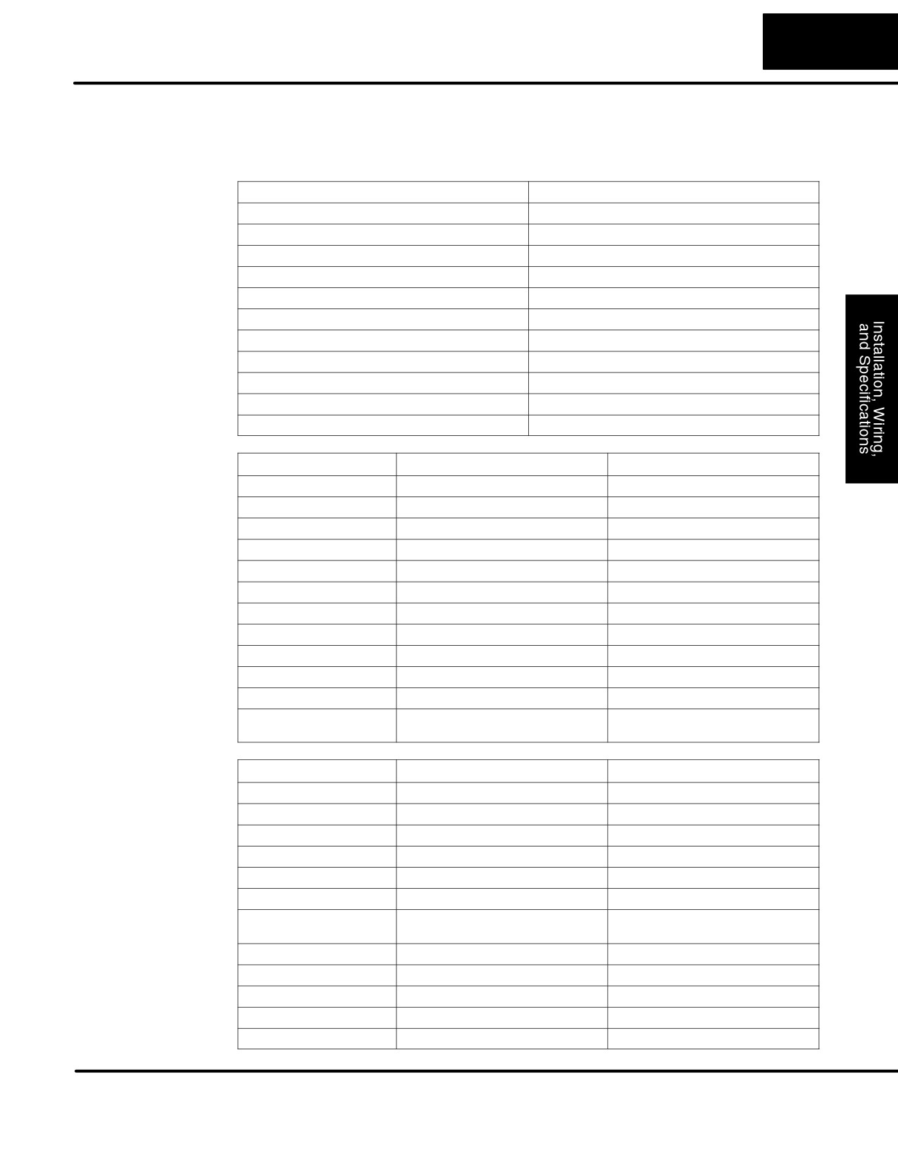
F1-130DD-D
External Power Requirements
10-30VDC, 1.5A
General
Communication Port
K-Sequence, 9600 baud, 8 data bits, odd parity
Specifications
Programming cable type
D2-DSCBL
Operating Temperature
32 to 140° F (0 to 60_ C)
Storage Temperature
-4 to 158° F (-20 to 70_ C)
Relative Humidity
5 to 95% (non-condensing)
Environmental air
No corrosive gases permitted
Vibration
MIL STD 810C 514.2
Shock
MIL STD 810C 516.2
Noise Immunity
NEMA ICS3-304
Terminal Type
Removable
Wire Gauge
One AWG14 or two AWG16, AWG24 minimum
DC Input
Parameter
High-Speed Inputs, X0 - X3
Standard DC Inputs X4 - X11
Specifications
Input Voltage Range
10 - 26.4 VDC
10 - 26.4 VDC or 21.6 - 26.4 VAC
Maximum Voltage
30 VDC (5 kHz maximum frequency)
30 VDC
Minimum Pulse Width
100 ms
N/A
ON Voltage Level
> 9.0 VDC
> 9.0 VDC
OFF Voltage Level
< 2.0 VDC
< 2.0 VDC
Input Impedance
2.8 kW @ 12 - 24 VDC
2.8 kW @ 12 - 24 VDC
Minimum ON Current
>3 mA
>3 mA
Maximum OFF Current
< 0.5 mA
<0.5 mA
OFF to ON Response
<50 mS
2 - 8 mS, 4 mS typical
ON to OFF Response
< 50 mS
2 - 8 mS, 4 mS typical
Status Indicators
Logic side
Logic side
Commons
4 channels / common x 1 bank
4 channels / common x 1 bank,
2 channels / common x 1 bank
DC Output
Parameter
Pulse Outputs, Y0 - Y1
Standard Outputs, Y2 - Y7
Specifications
Operating Voltage
5 - 30 VDC
5 - 30 VDC
Peak Voltage
60 VDC (7 kHz maximum frequency)
60 VDC
On Voltage Drop
0.4 VDC @ 0.25A
0.4 VDC @ 0.5A
Max Current (resistive)
0.5 A / point (subject to derating)
1.0 A / point (subject to derating)
Max leakage current
15 mA @ 30 VDC
15 mA @ 30 VDC
Max inrush current
1.5 A for 10 mS, 0.5 A for 100 mS
3 A for 10 mS, 1 A for 100 mS
Extenal DC power required
10 - 30 VDC @30 mA,
10 - 30 VDC @30 mA,
plus load current
plus load current
OFF to ON Response
<10 ms
3.5 ms
ON to OFF Response
<70 ms
110 ms
Status Indicators
Logic Side
Logic Side
Commons
Internally connected
Internally connected
Fuses
None
None
DL105 PLC User Manual, 2nd Edition, Rev. A
2-44
Installation, Wiring, and Specifications
Glossary of Specification Terms
Discrete Input
One of ten input connections to the PLC which converts an electrical signal
from a field device to a binary status (off or on), which is read by the
internal CPU each PLC scan.
Discrete Output
One of eight output connections from the PLC which converts an internal
ladder program result (0 or 1) to turn On or Off an output switching device.
This enables the program to turn on and off large field loads.
I/O Common
A connection in the input or output terminals which is shared by multiple
I/O circuits. It usually is in the return path to the power supply of the I/O
circuit.
Input Voltage Range
The operating voltage range of the input circuit.
Maximum Voltage
Maximum voltage allowed for the input circuit.
ON Voltage Level
The minimum voltage level at which the input point will turn ON.
OFF Voltage Level
The maximum voltage level at which the input point will turn OFF
Input Impedance
Input impedance can be used to calculate input current for a particular
operating voltage.
Input Current
Typical operating current for an active (ON) input.
Minimum ON Current
The minimum current for the input circuit to operate reliably in the ON
state.
Maximum OFF Current
The maximum current for the input circuit to operate reliably in the OFF
state.
OFF to ON Response
The time the module requires to process an OFF to ON state transition.
ON to OFF Response
The time the module requires to process an ON to OFF state transition.
Terminal Type
Indicates whether the terminal type is a removable or non-removable
connector or a fixed terminal.
Status Indicators
The LEDs that indicate the ON/OFF status of an input or output point. All
LEDs on DL105 Micro PLCs are electrically located on the logic side of the
input or output circuit.
DL105 PLC User Manual, 2nd Edition, Rev. A
3
High-Speed Input and
Pulse Output Features
In This Chapter
Ċ Introduction
Ċ Choosing the HSIO Operating Mode
Ċ Mode 10: HighĆSpeed Counter
Ċ Mode 20: Quadrature Counter
Ċ Mode 30: Pulse Output
Ċ Mode 40: HighĆSpeed Interrupt
Ċ Mode 50: Pulse Catch Input
Ċ Mode 60: Filtered Inputs
3-2
High-speed Input and Pulse Output Features
Introduction
Built-in Motion
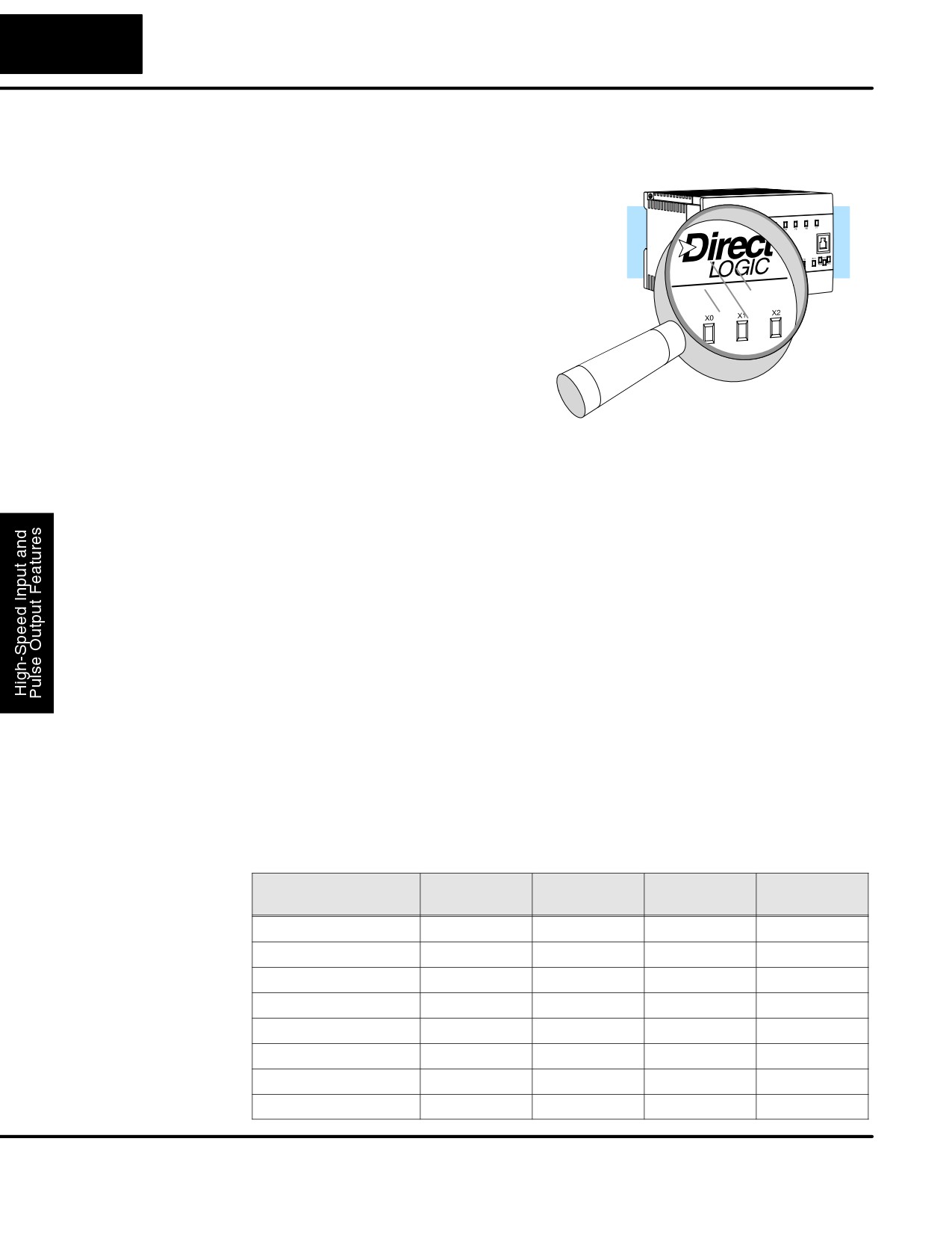
Many machine control applications
Control Solution
require various types of simple
high-speed monitoring and control. These
applications usually involve some type of
motion control, or high-speed interrupts
for time-critical events. The DL105 Micro
PLC solves this traditionally expensive
problem with built-in CPU enhancements.
ÎÎÎ
Let’s take a closer look at the available
ÎÎÎÎÎ
high-speed I/O features.
ÎÎÎÎÎÎ
ÎÎÎÎ
ÎÎ
The available high-speed input features are:
S High Speed Counter (5 kHz max.) with up to 24 counter presets and
built-in interrupt subroutine, counts up only, with reset
S Quadrature encoder inputs to measure counts and clockwise or counter
clockwise direction (5 kHz max.), counts up or down, with reset
S High-speed interrupt input for immediate response to critical or
time-sensitive tasks
S Pulse catch feature to monitor one input point, having a pulse width as
small as 100mS (0.1ms)
S Programmable discrete filtering (both on and off delay up to 99ms) to
ensure input signal integrity (this is the default mode for inputs X0-X3)
The available pulse output features are:
S Single-axis programmable pulse output (7 kHz max.) with three profile
types, including trapezoidal moves, registration, and velocity control
Availability of
IMPORTANT: Please note the following restrictions on availability of features:
HSIO Features
S High-speed input options are available only on DL105s with DC inputs.
S Pulse output options are available only on DL105s with DC outputs.
S Only one HSIO feature may be in use at one time. You cannot use a
high-speed input feature and the pulse output at the same time.
DL105
Discrete
Discrete
High-Speed
Pulse
Part Number
Input Type
Output Type
Input
Output
F1-130AR
AC
Relay
No
No
F1-130DR
DC
Relay
Yes
No
F1-130AD
AC
DC
No
Yes
F1-130DD
DC
DC
Yes
Yes
F1-130AA
AC
AC
No
No
F1-130DA
DC
AC
Yes
No
F1-130DR-D
DC
Relay
Yes
No
F1-130DD-D
DC
DC
Yes
Yes
DL105 PLC User Manual, 2nd Edition, Rev. A
3-3
High-Speed Input and Pulse Output Features
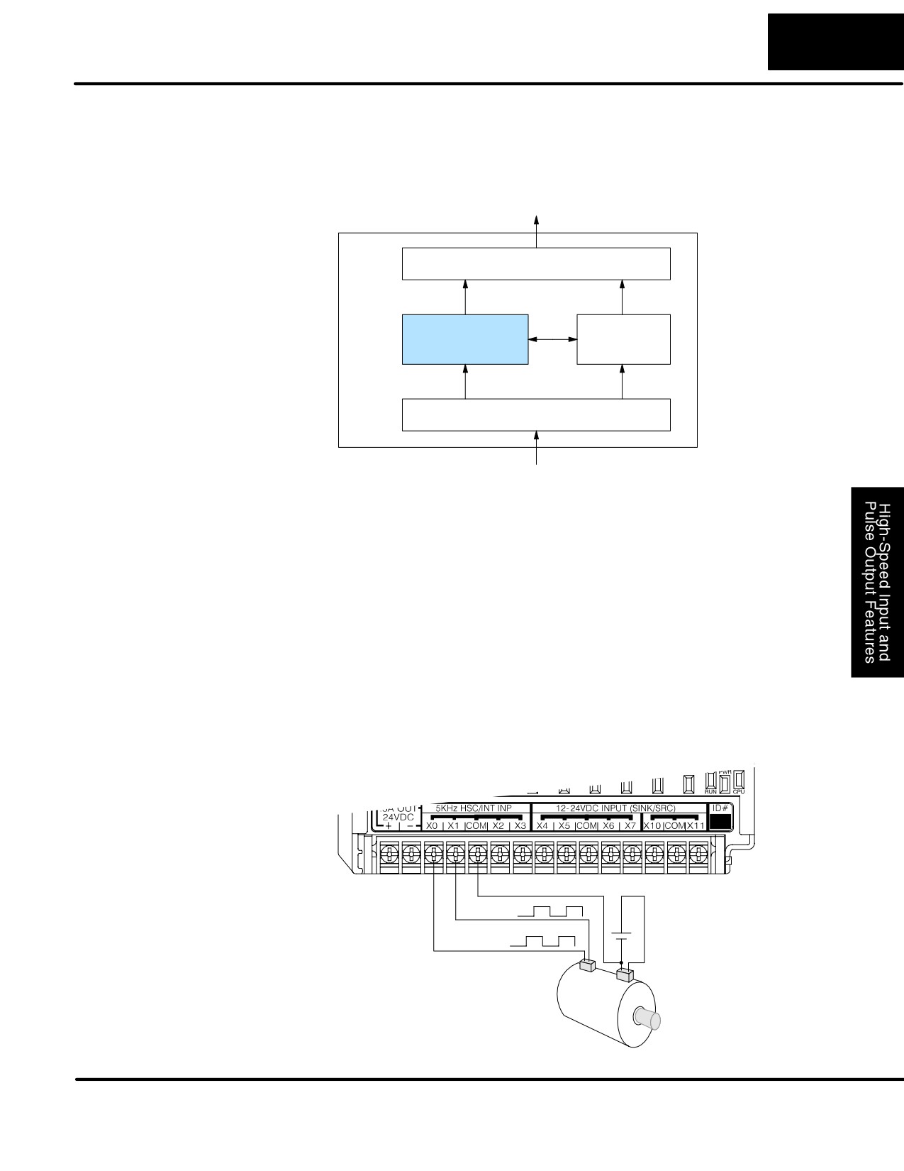
Dedicated High-
The internal CPU’s main task is to execute the ladder program and read/write all I/O
Speed I/O Circuit
points during each scan. In order to service high-speed I/O events, the DL105
includes a special circuit which is dedicated to a portion of the I/O points. Refer to the
DL105 block diagram in the figure below.
8 Discrete Outputs
DL105
Output Circuit
PLC
Y0, Y1
Y2 - Y7
High-Speed
CPU
I/O Circuit
X0 - X3
X4- X11
Input Circuit
10 Discrete Inputs
The high-speed I/O circuit (HSIO) is dedicated to the first four inputs (X0 - X3) and
the first two outputs (Y0 - Y1). We might think of this as a “CPU helper”. In the default
operation (called “Mode 60”) the HSIO circuit just passes through the I/O signals to
or from the CPU, so that all ten inputs behave equally and all eight outputs behave
equally. When the CPU is configured in any other HSIO Mode, the HSIO circuit
imposes a specialized function on the portion of inputs and outputs shown. The
HSIO circuit operates independently of the CPU program scan. This provides
accurate measurement and capturing of high-speed I/O activity while the CPU is
busy with ladder program execution.
Wiring Diagrams
After choosing the appropriate HSIO mode for your application, you’ll need to refer to
for Each HSIO
the section in this chapter for that specific mode. Each section includes wiring
Mode
diagram(s) to help you connect the High-Speed I/O points correctly to field devices.
An example of the quadrature counter mode diagram is shown below.
Signal Common
Phase B
+
12 - 24 VDC
Phase A
-
Encoder Input Wiring
Encoder
DL105 PLC User Manual, 2nd Edition, Rev. A
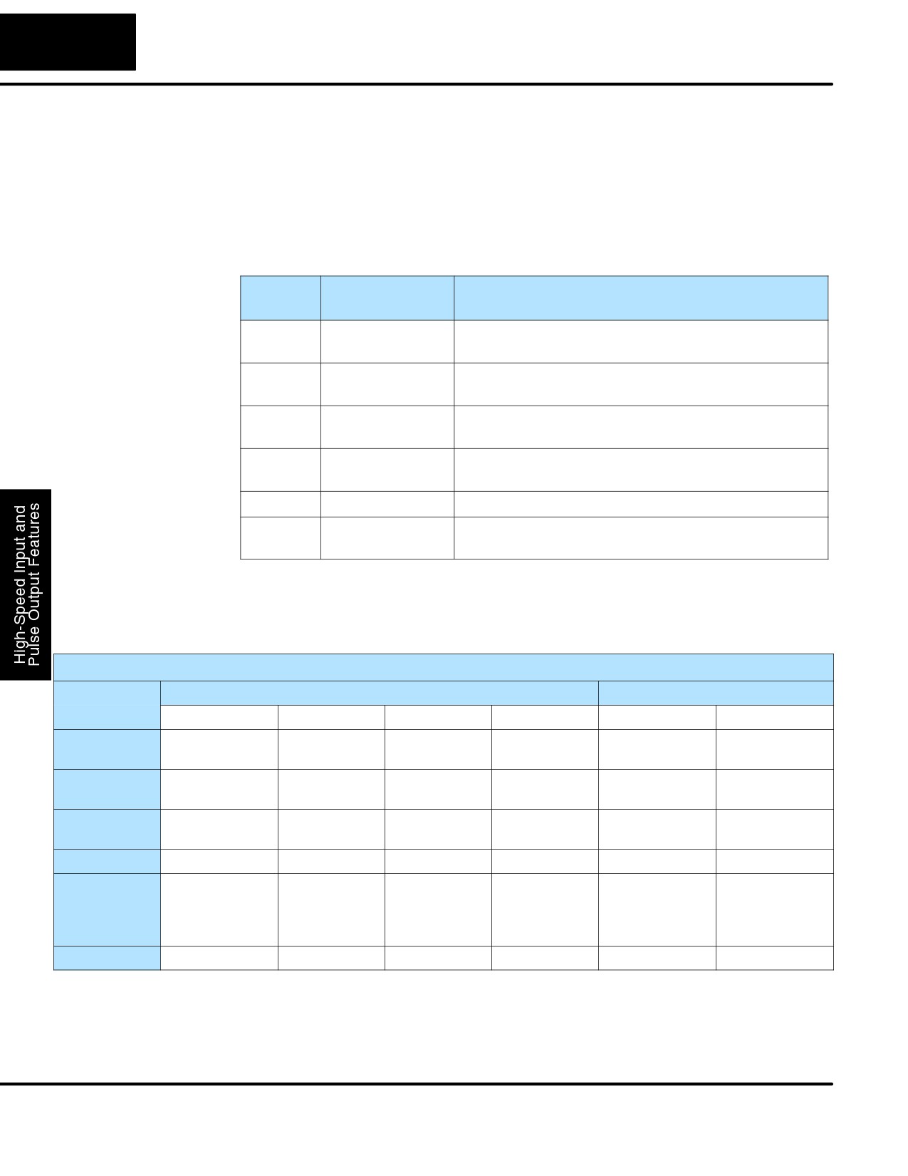
3-4
High-speed Input and Pulse Output Features
Choosing the HSIO Operating Mode
Understanding the
The High-Speed I/O circuit operates in one of 6 basic modes as listed in the table
Six Modes
below. The number in the left column is the mode number (later, we’ll use these
numbers to configure the PLC). Choose one of the following modes according to the
primary function you want from the dedicated High-Speed I/O circuit. You can simply
use all ten inputs and eight outputs as regular I/O points with Mode 60.
Mode
Mode Name
Mode Features
Number
10
High-Speed
5 kHz counter with 24 presets and reset input,
Counter
counts up only, causes interrupt on preset
20
Quadrature
Channel A / Channel B 5 kHz quadrature input,
Counter
counts up and down
30
Pulse Output
Stepper control - pulse and direction signals,
programmable motion profile
40
High-Speed
Generates an interrupt based on input transition
Interrupt
or time
50
Pulse Catch
Captures narrow pulses on a selected input
60
Discrete/Filtered
Rejects narrow pulses on selected inputs
Input
In choosing one of the six high-speed I/O modes, the I/O points listed in the table
below operate only as the function listed. If an input point is not specifically used to
support a particular mode, it usually operates as a filtered input by default. Similarly,
output points operate normally unless Pulse Output mode is selected.
Physical I/O Point Usage
DC Input Points
DC Output Points
Mode
X0
X1
X2
X3
Y0
Y1
High-Speed
Counter clock
Filtered Input
Filtered Input
Filtered Input
Regular Output
Regular Output
Counter
or Reset Cnt
Quadrature
Phase A Input
Phase B Input
FIltered Input
Filtered Input
Regular Output
Regular Output
Counter
or Reset Cnt
High-Speed
Interrupt Input,
Filtered Input
Filtered Input
Filtered Input
Regular Output
Regular Output
Interrupt
or Filtered Input
Pulse Catch
Pulse Input
Filtered Input
Filtered Input
Filtered Input
Regular Output
Regular Output
Pulse Output
Not available
Filtered Input
Filtered Input,
Filtered Input
Pulse
Direction
or Interrupt to
or
or
trigger pulse
CW Pulse
CCW Pulse
output
Filtered Input
Filtered Input
Filtered Input
Filtered Input
Filtered Input
Regular Output
Regular Output
Default Mode
Mode 60 (Filtered Inputs) is the default mode. The DL105 is initialized to this mode at
the factory, and any time you clear V-memory scratchpad. In the default condition,
X0-X3 are filtered inputs (10 mS delay) and Y0-Y1 are standard outputs.
DL105 PLC User Manual, 2nd Edition, Rev. A
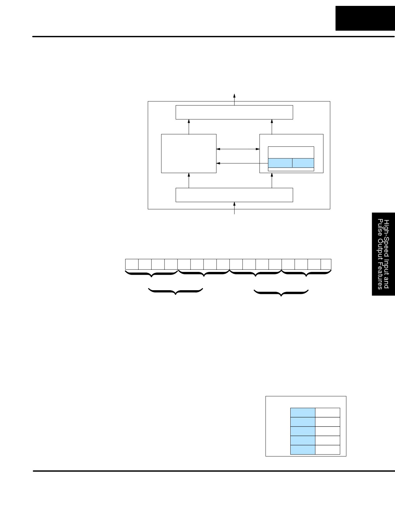
3-5
High-Speed Input and Pulse Output Features
Configuring the
If you have chosen a mode suited to the high-speed I/O needs of your application,
HSIO Mode
we’re ready to proceed to configure the PLC to operate accordingly. In the block
diagram below, notice the V-memory detail in the expanded CPU block. V-memory
location V7633 determines the functional mode of the high-speed I/O circuit. This is
the most important V-memory configuration value for HSIO functions!
Output Circuit
DL105
PLC
Y0, Y1
Y2 - Y7
CPU
I/O data
HighĆSpeed
VĆmemory
I/O Circuit
Mode Select
V7633
xxxx
X0 - X3
X4- X11
Input Circuit
The contents of V7633 is a 16-bit word, to be entered in binary-coded decimal. The
figure below defines what each 4-bit BCD digit of the word represents.
Memory Location V7633
Bits
15
14
13
12
11
10
9
8
7
6
5
4
3
2
1
0
0
0
1
0
0
0
0
0
0
1
0
1
0
0
0
0
2
0
5
0
Miscellaneous Setup (BCD)
HSIO Mode Setup (BCD)
00 = Power Up in Previous Mode
00 = Not Used
20 = Power Up in Run Mode Always
10 = High-Speed Counting Mode
20 = Quadrature Counting Mode
30 = Pulse Output Train
40 = High-Speed Interrupts
50 = Pulse Catching
60 = Discrete Filtered Inputs (default)
Bits 0 - 7 define the mode number 00, 10.. 60 previously referenced in this chapter.
The example data “2050” shown selects Mode 50 - Pulse Catch (BCD = 50) and
Power Up in Run Mode (BCD=20). Together they form the 4-digit BCD number 2050.
Configuring
In addition to configuring V7633 for the
VĆmemory
Inputs X0 - X3
HSIO mode, you’ll need to program the
next four locations in certain modes
Mode V7633
xxxx
according to the desired function of input
X0
V7634
xxxx
points X0 - X3. Other memory locations
X1
V7635
xxxx
may require configuring, depending on the
X2
V7636
xxxx
HSIO mode
(see the corresponding
X3
V7637
xxxx
section for particular HSIO modes).
DL105 PLC User Manual, 2nd Edition, Rev. A
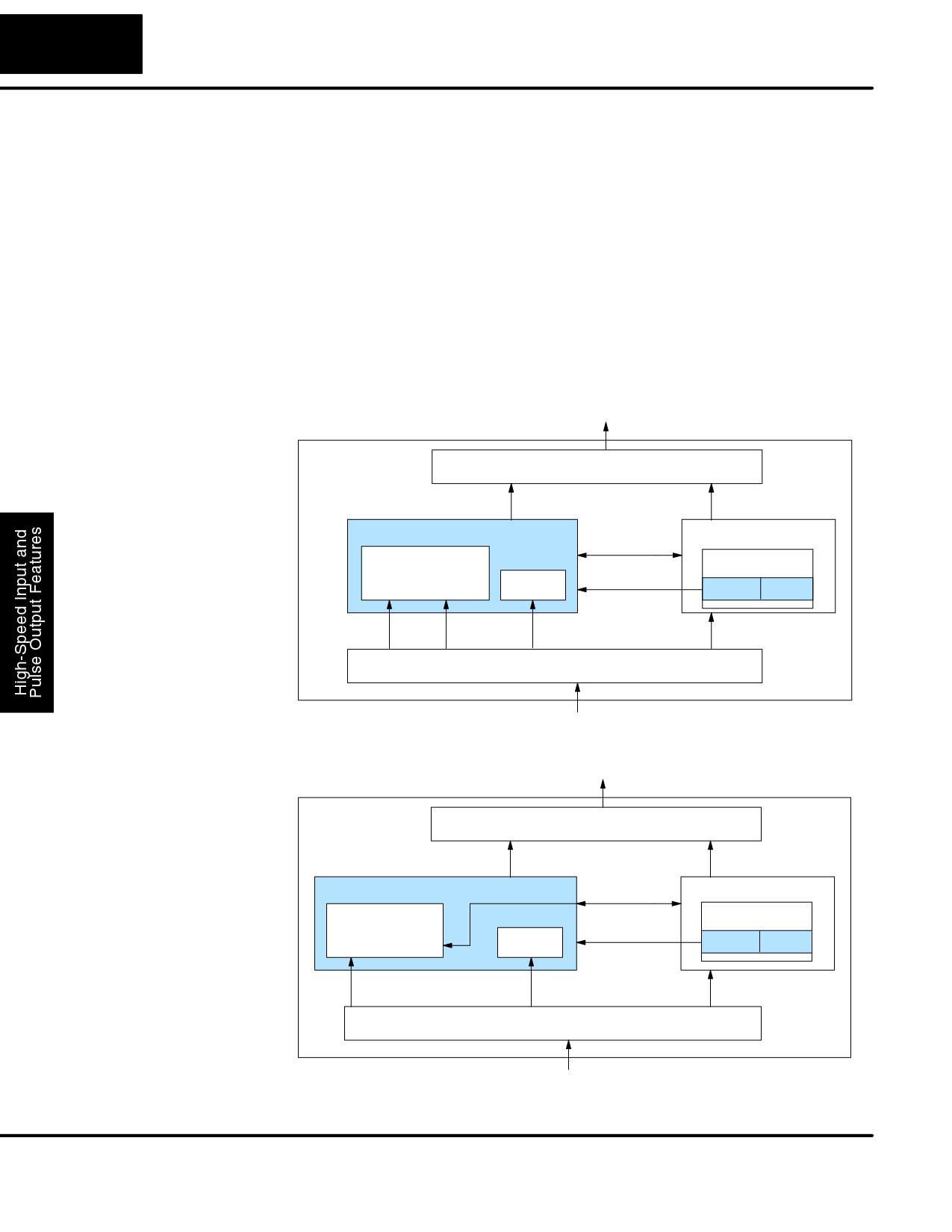
3-6
High-speed Input and Pulse Output Features
Mode 10: High-Speed Counter
Purpose
The HSIO circuit contains one high-speed counter. A single pulse train from an
external source (X0) clocks the counter on each signal leading edge. The counter
counts only upwards, from 0 to 99999999. The counter compares the current count
with up to 24 preset values, which you define. The purpose of the presets is to quickly
cause an action upon arrival at specific counts, making it ideal for such applications
as cut-to-length. It uses counter registers CT76 and CT77 in the CPU.
Functional Block Refer to the block diagram below. When the lower byte of HSIO Mode register V7633
Diagram
contains a BCD “10”, the high-speed up counter in the HSIO circuit is enabled. X0
automatically becomes the “clock” input for the high-speed counter, incrementing it
upon each off-to-on transition. The external reset input on X2 is the default
configuration for Mode 10. Inputs X1 and X3 are filtered inputs, available to the
ladder program.
DL105
Output Circuit
PLC
Y0, Y1
Y2 - Y7
HSIO
CPU
I/O data
COUNTER
VĆmemory
Mode Select
FILTER
CLK Reset
V7633
xx10
X0
X2
X1, X3
X4- X11
Input Circuit
Instead of using X2 as a dedicated reset input, you can configure X2 as a normal
filtered input. In this way, the counter reset must be generated in ladder logic.
DL105
Output Circuit
PLC
Y0, Y1
Y2 - Y7
HSIO
CPU
I/O data
VĆmemory
COUNTER
Mode Select
FILTER
V7633
xx10
CLK Reset
X0
X1, X2, X3
X4- X11
Input Circuit
Next, we will discuss how to program the high-speed counter and its presets.
DL105 PLC User Manual, 2nd Edition, Rev. A
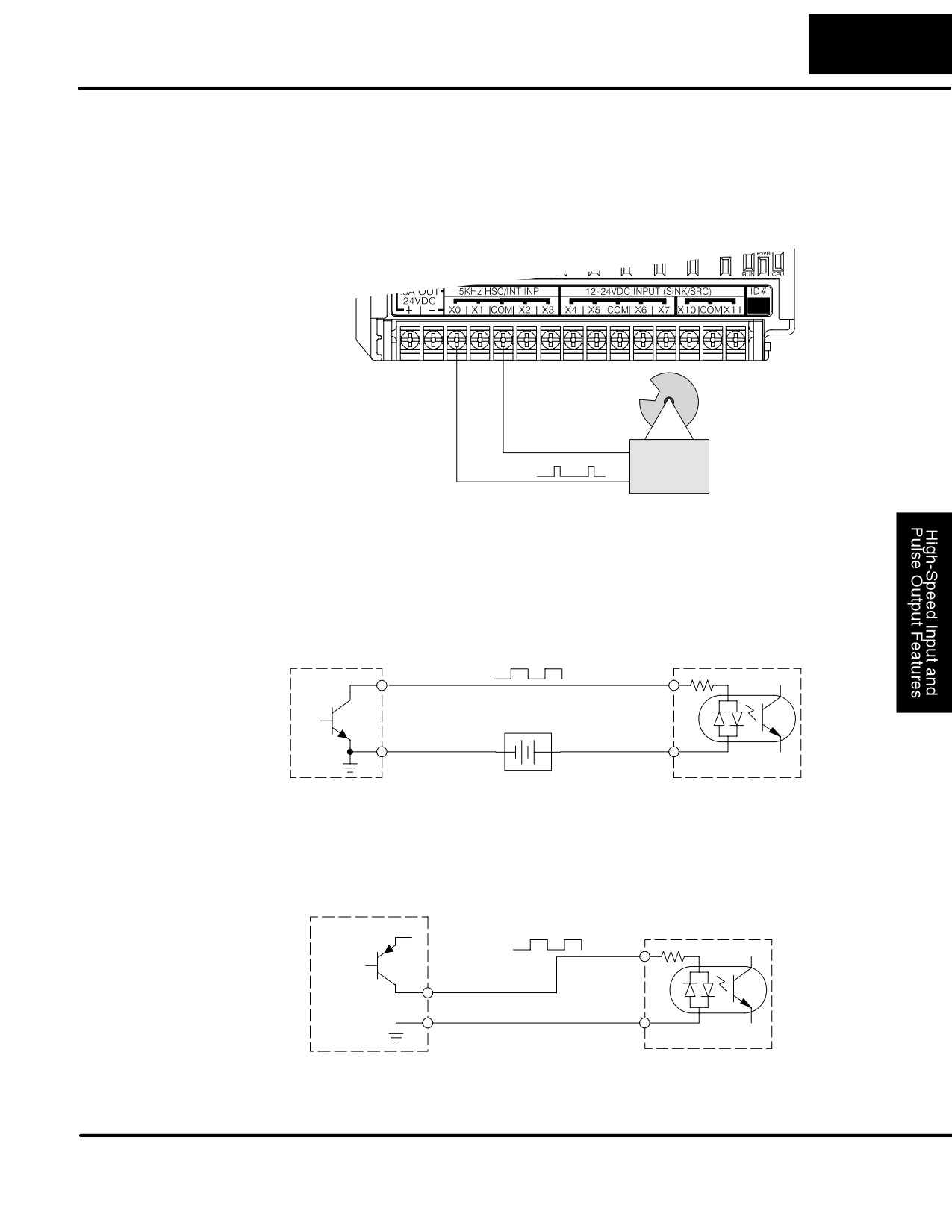
3-7
High-Speed Input and Pulse Output Features
A general wiring diagram for counters/encoders to the DL105 in HSIO Mode 10 is
Wiring Diagram
shown below. Many types of pulse-generating devices may be used, such as
proximity switches, single-channel encoders, magnetic or optical sensors, etc.
Devices with sinking outputs (NPN open collector) are probably the best choice for
interfacing. If the counter sources to the inputs, it must output 12 to 24 VDC. Note
that devices with 5V sourcing outputs will not work with DL105 inputs.
Signal Common
Counter Input Wiring
Signal
Interfacing to
The DL105’s DC inputs are flexible in that they detect current flow in either direction,
Counter Outputs
so they can be wired to a counter with either sourcing or sinking outputs. In the
following circuit, a counter has open-collector NPN transistor outputs. It sinks
current from the PLC input point, which sources current. The power supply can be
the +24VDC auxiliary supply or another supply (+12VDC or +24VDC), as long as the
input specifications are met.
Counter Output
X0 Input
Output
Input
(sinking)
(sourcing)
12Ć24 VDC Supply
Ground
-
+
Common
In the next circuit, an encoder has open-emitter PNP transistor outputs. It sources
current to the PLC input point, which sinks the current back to ground. Since the
encoder sources current, no additional power supply is required. However, note that
the encoder output must be 12 to 24 volts (5V encoder outputs will not work).
Counter Output
X0 Input
+12 to 24VDC
Input
(sinking)
Output (sourcing)
Ground
Common
DL105 PLC User Manual, 2nd Edition, Rev. A
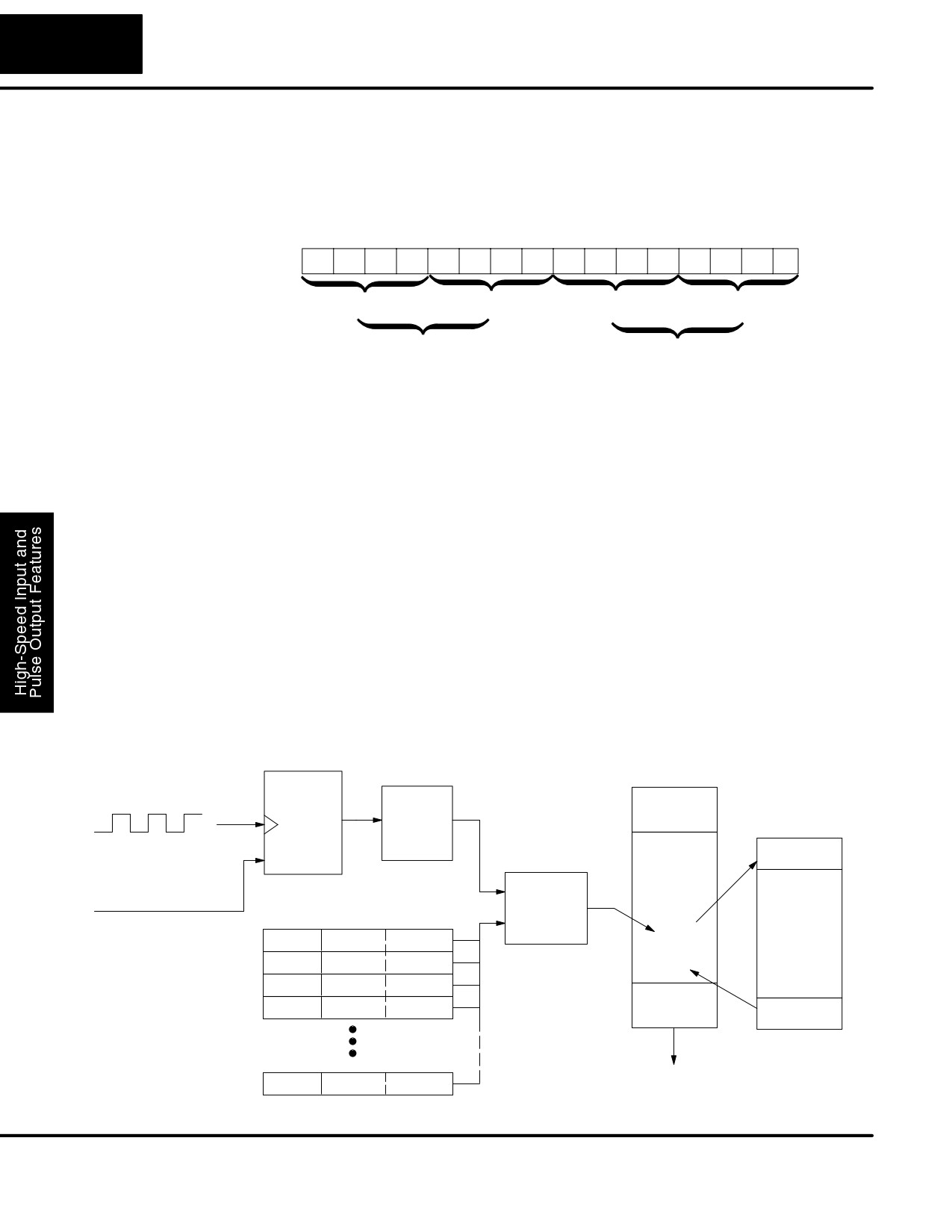
3-8
High-speed Input and Pulse Output Features
Recall that V7633 is the HSIO Mode Select register. Refer to the diagram below. Use
Setup for Mode 10
BCD 10 in the lower byte to select High-Speed Counter Mode. Use BCD 00 or 20 in
the upper byte as required. Combine the two bytes into a data word “xx10”, for writing
to V7633.
Memory Location V7633
Bits
15
14
13
12
11
10
9
8
7
6
5
4
3
2
1
0
0
0
1
0
0
0
0
0
0
0
0
1
0
0
0
0
2
0
1
0
Miscellaneous Setup (BCD)
HSIO Mode Setup (BCD)
00 = Power Up in Previous Mode
20 = Power Up in Run Mode Always
10 = High-Speed Counter
Choose the most convenient method of programming V7633 from the following:
S Include load and out instructions in your ladder program
S DirectSOFT32’s memory editor
S Use the Handheld Programmer D2-HPP
We recommend using the first method above so that the HSIO setup becomes an
integral part of your application program. An example program later in this section
shows how to to this.
Presets and
The goal of counting is to do a special action when the count reaches a preset value.
Special Relays
Refer to the figure below. The counter features 24 presets, which you can program.
A preset is a number you derive and store so that the counter will constantly compare
the current count with the preset. When the two are equal, a special relay contact is
energized and program execution jumps to the interrupt routine. We recommend
using the special relay(s) in the interrupt service routine to cause any immediate
action you desire. After the interrupt service routine is complete, the CPU returns to
the ladder program, resuming program execution from the point of interruption. The
compare function is ready for the next preset event.
CPU Scan
Counter
Input
Current
Update
Value
X0, counter clock
Ladder
INT
Reset
Program
Does
Execution
HSIO
X2, external reset
=
Count =
Interrupt
VĆmemory Preset Data
Preset?
Routine
V2320
0000
1000
Current
Program
instruction
V2322
0000
2000
SPxxx
V2324
0000
2500
Output
V2326
0000
3175
Update
IRT
V2376
0921
0000
DL105 PLC User Manual, 2nd Edition, Rev. A
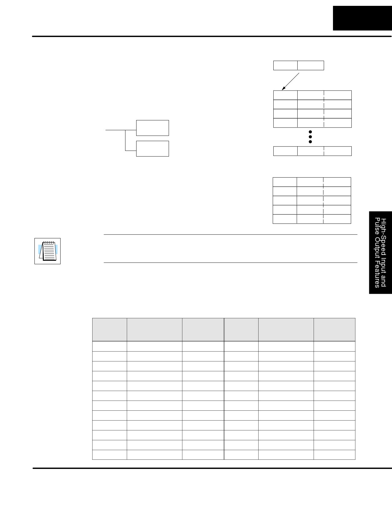
3-9
High-Speed Input and Pulse Output Features
Preset Data
V7630 is a pointer location which points to
Preset Table Pointer
Starting Location
the beginning of the Preset Data Table.
V7630
2000
The default starting location for the Preset
Data Table is V2320
(default after
Preset Data
initializing
scratchpad
V-memory).
However, you may change this by
V2000
0000
1000
programming a different value in V7630.
V2002
0000
2000
Use the LDA and OUT instructions as
V2004
0000
2500
shown:
Load the octal address,
V2006
0000
3175
LDA
convert to hex, leave
O2000
result in accumulator.
Output this address to
OUT
V7630, the location of the
V7630
V2076
0000
0000
pointer to the Preset data.
Using Fewer than
When using fewer than
24 preset
Preset Data
24 Presets
registers, the HSIO looks for “0000 FFFF”
V2320
0000
1000
(use LDD Kffff) in the next preset location
V2322
0000
2000
to indicate the last preset has been
reached. The example to the right uses
V2324
0000
2500
four presets. The
0000 FFFF in
V2326
0000
3175
V2331-V2330 indicates the previous
V2330
0000
FFFF
preset was the last.
NOTE: Each successive preset must be greater than the previous preset value. If a
preset value is less than a lower-numbered preset value, the CPU cannot compare
for that value, since the counter can only count upwards.
Equal Relay
The following table lists all 24 preset register default locations. Each occupies two
Numbers
16-bit V-memory registers. The corresponding special relay contact number is in the
next column. We might also call these “equal” relay contacts, because they are true
(closed) when the present high-speed counter value is equal to the preset value.
Each contact remains closed until the counter value equals the next preset value.
Preset
Preset
Special
Preset
Preset
Special
V-memory Regis-
Relay
V-memory Regis-
Relay
ter
Number
ter
Number
1
V2321 / V2320
SP540
13
V2351 / V2350
SP554
2
V2323 / V2322
SP541
14
V2353 / V2352
SP555
3
V2325 / V2324
SP542
15
V2355 / V2354
SP556
4
V2327 / V2326
SP543
16
V2357 / V2356
SP557
5
V2331 / V2330
SP544
17
V2361 / V2360
SP560
6
V2333 / V2332
SP545
18
V2363 / V2362
SP561
7
V2335 / V2334
SP546
19
V2365 / V2364
SP562
8
V2337 / V2336
SP547
20
V2367 / V2366
SP563
9
V2341 / V2340
SP550
21
V2371 / V2370
SP564
10
V2343 / V2342
SP551
22
V2373 / V2372
SP565
11
V2345 / V2344
SP552
23
V2375 / V2374
SP566
12
V2347 / V2346
SP553
24
V2377 / V2376
SP567
DL105 PLC User Manual, 2nd Edition, Rev. A