DL105 Micro PLC. User Manual (2003) - page 1
1
Manual Revisions
If you contact us in reference to this manual, remember to include the revision number.
Title: DL105 Micro PLC User Manual
Manual Number: D1-USER-M
Edition/Rev
Date
Description of Changes
Original
9/96
Original Issue
2nd Edition
5/98
Updated
2nd Edition,
7/03
Updated with corrections and a new appendix
Rev. A
1
i
Table of Contents
Chapter 1: Getting Started
Introduction
1-2
The Purpose of this Manual
1-2
Where to Begin
1-2
Supplemental Manuals
1-2
Technical Support
1-2
Conventions Used
1-3
Appendices
1-4
DL105 Micro PLC Components
1-5
The DL105 Micro PLC Family
1-5
Programming Methods
1-5
DirectSOFT32 Programming for Windows
1-5
Handheld Programmer
1-6
I/O Quick Chart Selection
1-6
Quick Start for PLC Checkout and Programming
1-7
Step 1: Unpack the DL105 Equipment
1-7
Step 2: Connect Switches to Input Terminals
1-8
Step 3: Connect the Power Wiring
1-9
Step 4: Connect the Programming Device
1-9
Step 5: Switch on the System Power
1-10
Step 6: Initialize Scratchpad Memory
1-10
Step 7: Enter a Ladder Program
1-10
Steps to Designing a Successful System
1-11
Step 1: Review the Installation Guidelines
1-11
Step 2:Understand the PLC Setup Procedures
1-11
Step 3: Review the I/O Selection Criteria
1-11
Step 4: Choose a System Wiring Strategy
1-11
Step 5: Understand the System Operation
1-11
Step 6: Review the Programming Concepts
1-12
Step 7: Choose the Instructions
1-12
Step 8: Understand the Maintenance and Troubleshooting Procedures .
1-12
Questions and Answers about DL105 Micro PLCs
1-13
Chapter 2: Installation, Wiring, and Specifications
Safety Guidelines
2-2
Plan for Safety
2-2
Three Levels of Protection
2-2
Orderly System Shutdown
2-3
System Power Disconnect
2-3
Emergency Stop
2-3
Orientation to DL105 Front Panel
2-4
Accessing the I/O Terminals
2-4
Protective Sheet for DL105 Vents
2-5
Connector Removal
2-5
ii
Table of Contents
Mounting Guidelines
2-6
Unit Dimensions
2-6
Enclosures
2-6
Panel Layout & Clearances
2-7
Agency Approvals
2-8
Environmental Specifications
2-8
Using Mounting Rails
2-9
Wiring Guidelines
2-10
Power Input Wiring
2-10
Fuse Protection for Input Power
2-10
External Power Source
2-11
Planning the Wiring Routes
2-12
Fuse Protection for Input and Output Circuits
2-12
I/O Point Numbering
2-12
System Wiring Strategies
2-13
PLC Isolation Boundaries
2-13
Powering I/O Circuits with the Auxiliary Supply
2-14
Powering I/O Circuits Using Separate Supplies
2-15
Connecting Operator Interface Devices
2-16
Connecting Programming Devices
2-16
Sinking / Sourcing Concepts
2-17
I/O “Common” Terminal Concepts
2-18
Connecting DC I/O to “Solid State” Field Devices
2-19
Solid State Input Sensors
2-19
Solid State Output Loads
2-19
Relay Output Wiring Methods
2-21
Surge Suppresion For Inductive Loads
2-22
Prolonging Relay Contact Life
2-23
DC Input Wiring Methods
2-24
DC Output Wiring Methods
2-25
High-Speed I/O Wiring Methods
2-26
F1-04SIM Input Simulator Wiring
2-27
Wiring Diagrams and Specifications
2-28
F1-130AR I/O Wiring Diagram
2-28
F1-130AR General Specifications
2-29
F1-130DR/F1-130DR-CE I/O Wiring Diagram
2-30
F1-130DR/F1-130DR-CE General Specifications
2-31
F1-130AD I/O Wiring Diagram
2-32
F1-130AD General Specifications
2-33
F1-130DD/F1-130DD-CE I/O Wiring Diagram
2-34
F1-130DD/F130-DD-CE General Specifications
2-35
F1-130AA I/O Wiring Diagram
2-36
F1-130AA General Specifications
2-37
F1-130DA I/O Wiring Diagram
2-38
F1-130DA General Specifications
2-39
F1-130DR-D I/O Wiring Diagram
2-40
F1-130DR-D General Specifications
2-41
F1-130DD-D I/O Wiring Diagram
2-42
F1-130DD-D General Specifications
2-43
Glossary of Specification Terms
2-44
iii
Table of Contents
Chapter 3: High-Speed Input and Pulse Output Features
Introduction
3-2
Built-in Motion Control Solution
3-2
Availability of HSIO Features
3-2
Dedicated High- Speed I/O Circuit
3-3
Wiring Diagrams for Each HSIO Mode
3-3
Choosing the HSIO Operating Mode
3-4
Understanding the Six Modes
3-4
Default Mode
3-4
Configuring the HSIO Mode
3-5
Configuring Inputs X0 - X3
3-5
Mode 10: High-Speed Counter
3-6
Purpose
3-6
Functional Block Diagram
3-6
Wiring Diagram
3-7
Interfacing to Counter Outputs
3-7
Setup for Mode 10
3-8
Presets and Special Relays
3-8
Preset Data Starting Location
3-9
Using Fewer than 24 Presets
3-9
Equal Relay Numbers
3-9
Calculating Your Preset Values
3-10
X Input Configuration
3-10
Writing Your Control Program
3-11
Program Example: Counter Without Preset
3-11
Program Example Cont’d
3-12
Counter With Presets Program Example
3-13
Counter With Preload Program Example
3-15
Troubleshooting Guide for Mode 10
3-16
Mode 20: Quadrature Counter
3-17
Purpose
3-17
Functional Block Diagram
3-17
Quadrature Encoder Signals
3-17
Wiring Diagram
3-18
Interfacing to Encoder Outputs
3-18
Setup for Mode 20
3-19
X Input Configuration
3-19
Writing Your Control Program
3-20
Quadrature Counter w/Preload Program Example
3-20
Program Example Cont’d
3-21
Counter Preload Program Example
3-22
Troubleshooting Guide for Mode 20
3-22
Mode 30: Pulse Output
3-23
Purpose
3-23
Functional Block Diagram
3-24
Wiring Diagram
3-25
Interfacing to Drive Inputs
3-25
Motion Profile Specifications
3-26
Physical I/O Configuration
3-26
Logical I/O Functions
3-26
iv
Table of Contents
Setup for Mode 30
3-27
Profile / Velocity Select Register
3-27
Profile Parameter Table
3-28
Trapezoidal Profile
3-28
Registration Profile
3-28
Velocity Profile
3-28
Choosing the Profile Type
3-29
Trapezoidal Profile Defined
3-29
Registration and Home Search Profiles Defined
3-29
Velocity Profile Defined
3-29
Trapezoidal Profile Operation
3-30
Trapezoidal Profile Applications
3-30
Trapezoidal Profile Program Example
3-31
Program Example Cont’d
3-32
Preload Position Value
3-32
Registration Profile Operation
3-33
Registration Applications
3-33
Registration Profile Program Example
3-34
Program Example Cont’d
3-35
Home Search Program Example
3-36
Velocity Profile Operation
3-38
Velocity Profile Applications
3-38
Velocity Profile Program Example
3-39
Program Example Cont’d
3-40
Pulse Output Error Codes
3-41
Troubleshooting Guide for Mode 30
3-41
Mode 40: High-Speed Interrupts
3-43
Purpose
3-43
Functional Block Diagram
3-43
Setup for Mode 40
3-44
Interrupts and the Ladder Program
3-44
External Interrupt Timing Parameters
3-45
Timed Interrupt Parameters
3-45
X Input / Timed INT Configuration
3-45
External Interrupt Program Example
3-46
Timed Interrupt Program Example
3-47
Mode 50: Pulse Catch Input
3-48
Purpose
3-48
Functional Block Diagram
3-48
Pulse Catch Timing Parameters
3-48
Setup for Mode 50
3-49
X Input Configuration
3-49
Pulse Catch Program Example
3-50
Mode 60: Discrete Inputs with Filter
3-51
Purpose
3-51
Functional Block Diagram
3-51
Input Filter Timing Parameters
3-51
Setup for Mode 60
3-52
X Input Configuration
3-52
Filtered Inputs Program Example
3-53
v
Table of Contents
Chapter 4: CPU Specifications and Operation
Introduction
4-2
DL105 CPU Features
4-2
CPU Specifications
4-3
CPU Hardware Setup
4-4
Communication Port Pinout Diagrams
4-4
Connecting the Programming Devices
4-5
CPU Setup Information
4-5
CPU Modes
4-6
Mode of Operation at Power-up
4-6
Changing Modes in the DL105 PLC
4-6
Setting Bits in V7633
4-7
Auxiliary Functions
4-8
Clearing an Existing Program
4-9
Initializing System Memory
4-9
Setting Retentive Memory Ranges
4-9
Using a Password
4-10
CPU Operation
4-11
CPU Operating System
4-11
Program Mode
4-12
Run Mode
4-12
Read Inputs
4-13
Service Peripherals and Force I/O
4-13
Update Special Relays and Special Registers
4-13
Solve Application Program
4-14
Write Outputs
4-14
Diagnostics
4-14
I/O Response Time
4-15
Is Timing Important for Your Application?
4-15
Normal Minimum I/O Response
4-15
Normal Maximum I/O Response
4-16
Improving Response Time
4-17
CPU Scan Time Considerations
4-18
Reading Inputs
4-18
Writing Outputs
4-18
Application Program Execution
4-19
PLC Numbering Systems
4-20
PLC Resources
4-20
V-Memory
4-21
Binary-Coded Decimal Numbers
4-21
Hexadecimal Numbers
4-21
Memory Map
4-22
Octal Numbering System
4-22
Discrete and Word Locations
4-22
V Memory Locations for Discrete Memory Areas
4-22
Input Points (X Data Type)
4-23
Output Points (Y Data Type)
4-23
Control Relays (C Data Type)
4-23
Timers and Timer Status Bits (T Data type)
4-23
vi
Table of Contents
Timer Current Values (V Data Type)
4-24
Counters and Counter Status Bits (CT Data type)
4-24
Counter Current Values (V Data Type)
4-24
Word Memory (V Data Type)
4-25
Stages (S Data type)
4-25
Special Relays (SP Data Type)
4-25
DL105 System V-memory
4-26
System Parameters and Default Data Locations (V Data Type)
4-26
DL105 Memory Map
4-28
X Input Bit Map
4-29
Y Output Bit Map
4-29
Control Relay Bit Map
4-29
Stage Control / Status Bit Map
4-30
Timer Status Bit Map
4-30
Counter Status Bit Map
4-30
Chapter 5: Standard RLL Instructions
Introduction
5-2
Using Boolean Instructions
5-3
END Statement
5-3
Simple Rungs
5-3
Normally Closed Contact
5-3
Contacts in Series
5-4
Midline Outputs
5-4
Parallel Elements
5-4
Joining Series Branches in Parallel
5-5
Joining Parallel Branches in Series
5-5
Combination Networks
5-5
Comparative Boolean
5-5
Boolean Stack
5-6
Immediate Boolean
5-7
Boolean Instructions
5-8
Store (STR)
5-8
Store Not (STRN)
5-8
Or (OR)
5-9
Or Not (ORN)
5-9
And (AND)
5-10
And Not (ANDN)
5-10
And Store (AND STR)
5-11
Or Store (OR STR)
5-11
Out (OUT)
5-13
Or Out (OR OUT)
5-13
Positive Differential (PD)
5-14
Set (SET)
5-14
Reset (RST)
5-14
Set, Reset Instr. Continued
5-15
Pause (PAUSE)
5-15
Comparative Boolean
5-16
Store If Equal (STRE)
5-16
vii
Table of Contents
Store If Not Equal (STRNE)
5-16
Or If Equal (ORE)
5-17
Or If Not Equal (ORNE)
5-17
And If Equal (ANDE)
5-18
And If Not Equal (ANDNE)
5-18
Store (STR)
5-19
Store Not (STRN)
5-19
Or (OR)
5-20
Or Not (ORN)
5-20
And (AND)
5-21
And Not (ANDN)
5-21
Immediate Instructions
5-22
Store Immediate (STRI)
5-22
Store Not Immediate (STRNI)
5-22
Or Immediate (ORI)
5-22
Or Not Immediate (ORNI)
5-22
OR Immediate Instructions Cont’d
5-23
And Immediate (ANDI)
5-23
And Not Immediate (ANDNI)
5-23
Or Out Immediate (OROUTI)
5-24
Set Immediate (SETI)
5-25
Reset Immediate (RSTI)
5-25
Timer, Counter and Shift Register Instructions
5-26
Using Timers
5-26
Timer (TMR) and Timer Fast (TMRF)
5-27
Timer Example Using Discrete Status Bits
5-28
Timer Example Using Comparative Contacts
5-28
Accumulating Timer (TMRA) Accumulating Fast Timer (TMRAF) .
5-29
Accumulating Timer Example using Discrete Status Bits
5-30
Accumulator Timer Example Using Comparative Contacts
5-30
Using Counters
5-31
Counter (CNT)
5-32
Counter Example Using Discrete Status Bits
5-33
Counter Example Using Comparative Contacts
5-33
Stage Counter (SGCNT)
5-34
Stage Counter Example Using Discrete Status Bits
5-35
Stage Counter Example Using Comparative Contacts
5-35
Up Down Counter (UDC)
5-36
Up / Down Counter Example Using Discrete Status Bits
5-37
Up / Down Counter Example Using Comparative Contacts
5-37
Shift Register (SR)
5-38
Accumulator / Stack Load and Output Data Instructions
5-39
Using the Accumulator
5-39
Copying Data to the Accumulator
5-39
Changing the Accumulator Data
5-40
Using the Accumulator Stack
5-41
Using Pointers
5-42
Load (LD)
5-44
Load Double (LDD )
5-45
Load Formatted (LDF)
5-46
Load Address (LDA)
5-47
viii
Table of Contents
Out (OUT)
5-48
Out Double (OUTD)
5-48
Out Formatted (OUTF)
5-49
Pop (POP)
5-49
Pop Instruction Continued
5-50
Logical Instructions (Accumulator)
5-51
And (AND)
5-51
And Double (ANDD)
5-52
Or (OR)
5-53
Or Double (ORD)
5-54
Exclusive Or (XOR)
5-55
Exclusive Or Double (XORD)
5-56
Compare (CMP)
5-57
Compare Double (CMPD)
5-58
Math Instructions
5-59
Add (ADD)
5-59
Add Double (ADDD)
5-60
Subtract (SUB)
5-61
Subtract Double (SUBD)
5-62
Multiply (MUL)
5-63
Divide (DIV)
5-64
Increment Binary (INCB)
5-65
Decrement Binary (DECB)
5-65
Bit Operation Instructions
5-66
Shift Left (SHFL)
5-66
Shift Right (SHFR)
5-67
Encode (ENCO)
5-68
Decode (DECO)
5-69
Number Conversion Instructions (Accumulator)
5-70
Binary (BIN)
5-70
Binary Coded Decimal (BCD)
5-71
Invert (INV)
5-72
Table Instructions
5-73
Move (MOV)
5-73
Move Memory Cartridge / Load Label (MOVMC), (LDLBL)
5-74
Copy Data From a Data Label Area to V Memory
5-75
CPU Control Instructions
5-76
No Operation (NOP)
5-76
End (END)
5-76
Stop (STOP)
5-76
Program Control Instructions
5-77
Master Line Set (MLS)
5-77
Master Line Reset (MLR)
5-77
Understanding Master Control Relays
5-77
MLS/MLR Example
5-78
Interrupt Instructions
5-79
Interrupt (INT)
5-79
Interrupt Return (IRT)
5-79
Enable Interrupts (ENI)
5-79
Disable Interrupts (DISI)
5-79
ix
Table of Contents
External Interrupt Program Example
5-80
Timed Interrupt Program Example
5-81
Message Instructions
5-82
Fault (FAULT)
5-82
Fault Example
5-82
Data Label (DLBL)
5-83
ASCII Constant (ACON)
5-83
Numerical Constant (NCON)
5-83
Data Label Example
5-84
Chapter 6: Drum Instruction Programming
Introduction
6-2
Purpose
6-2
Drum Terminology
6-2
Drum Chart Representation
6-3
Output Sequences
6-3
Step Transitions
6-4
Drum Instruction Parameters
6-4
Timer-Only Transitions
6-4
Timer and Event Transitions
6-5
Event-Only Transitions
6-6
Counter Assignments
6-6
Last Step Completion
6-7
Overview of Drum Operation
6-8
Drum Instruction Block Diagram
6-8
Powerup State of Drum Registers
6-9
Drum Control Techniques
6-10
Drum Control Inputs
6-10
Self-Resetting Drum
6-11
Initializing Drum Outputs
6-11
Using Complex Event Step Transitions
6-11
Drum Instruction
6-12
Event Drum (EDRUM)
6-12
Handheld Programer Drum Mnemonics
6-14
Chapter 7: RLLPLUS Stage Programming
Introduction to Stage Programming
7-2
Overcoming “Stage Fright”
7-2
Learning to Draw State Transition Diagrams
7-3
Introduction to Process States
7-3
The Need for State Diagrams
7-3
A 2-State Process
7-3
RLL Equivalent
7-4
Stage Equivalent
7-4
Let’s Compare
7-5
Initial Stages
7-5
What Stage Bits Do
7-6
Stage Instruction Characteristics
7-6
Using the Stage Jump Instruction for State Transitions
7-7
x
Table of Contents
Stage Jump, Set, and Reset Instructions
7-7
Stage Program Example: Toggle On/Off Lamp Controller
7-8
A 4-State Process
7-8
Four Steps to Writing a Stage Program
7-9
Stage Program Example: A Garage Door Opener
7-10
Garage Door Opener Example
7-10
Draw the Block Diagram
7-10
Draw the State Diagram
7-11
Add Safety Light Feature
7-12
Modify the Block Diagram and State Diagram
7-12
Using a Timer Inside a Stage
7-13
Add Emergency Stop Feature
7-14
Exclusive Transitions
7-14
Stage Program Design Considerations
7-15
Stage Program Organization
7-15
How Instructions Work Inside Stages
7-16
Using a Stage as a Supervisory Process
7-17
Stage Counter
7-17
Power Flow Transition Technique
7-18
Stage View in DirectSOFT
7-18
RLLPLUS Stage Instructions
7-19
Staget (SG)
7-19
Initial Staget (ISG)
7-20
JUMP (JMP)
7-20
Questions and Answers about Stage Programming
7-21
Chapter 8: Maintenance and Troubleshooting
Hardware System Maintenance
8-2
Diagnostics
8-2
CPU Indicators
8-6
Communications Problems
8-7
I/O Point Troubleshooting
8-8
Noise Troubleshooting
8-10
Machine Startup and Program Troubleshooting
8-11
Appendix E: Auxiliary Functions
Introduction
A-2
Purpose of Auxiliary Functions
A-2
Accessing AUX Functions via DirectSOFT
A-3
Accessing AUX Functions via the Handheld Programmer
A-3
AUX 2* — RLL Operations
A-4
AUX 21 Check Program
A-4
AUX 22 Change Reference
A-4
AUX 23 Clear Ladder Range
A-4
AUX 24 Clear Ladders
A-4
AUX 3* — V-memory Operations
A-4
AUX 31 Clear V Memory
A-4
AUX 4* — I/O Configuration
A-4
xi
Table of Contents
AUX 41 Show I/O Configuration
A-4
AUX 5* — CPU Configuration
A-5
AUX 51 Modify Program Name
A-5
AUX 53 Display Scan Time
A-5
AUX 54 Initialize Scratchpad
A-5
AUX 55 Set Watchdog Timer
A-5
AUX 57 Set Retentive Ranges
A-5
AUX 58 Test Operations
A-6
AUX 5B Counter Interface Configuration
A-6
AUX 6* — Handheld Programmer Configuration
A-6
AUX 61 Show Revision Numbers
A-6
AUX 62 Beeper On / Off
A-6
AUX 65 Run Self Diagnostics
A-6
AUX 7* — EEPROM Operations
A-7
Transferrable Memory Areas
A-7
AUX 71 CPU to HPP EEPROM
A-7
AUX 72 HPP EEPROM to CPU
A-7
AUX 73 Compare HPP EEPROM to CPU
A-7
AUX 74 HPP EEPROM Blank Check
A-7
AUX 75 Erase HPP EEPROM
A-7
AUX 76 Show EEPROM Type
A-7
AUX 8* — Password Operations
A-8
AUX 81 Modify Password
A-8
AUX 82 Unlock CPU
A-8
AUX 83 Lock CPU
A-8
Appendix B: DL105 Error Codes
Appendix C: Instruction Execution Times
Introduction
C-2
V-Memory Data Registers
C-2
V-Memory Bit Registers
C-2
How to Read the Tables
C-2
Instruction Execution Times
C-3
Boolean Instructions
C-3
Comparative Boolean Instructions
C-3
Immediate Instructions
C-6
Timer, Counter, Shift Register, EDRUM Instructions
C-6
Accumulator Data Instructions
C-7
Logical Instructions
C-8
Math Instructions
C-8
Bit Instructions
C-9
Number Conversion Instructions
C-9
Table Instructions
C-9
CPU Control Instructions
C-10
Program Control Instructions
C-10
Interrupt Instructions
C-10
Message Instructions
C-10
RLLPLUS Instructions
C-10
xii
Table of Contents
Appendix D: Special Relays
DL105 PLC Special Relays
D-2
Startup and Real-Time Relays
D-2
CPU Status Relays
D-2
System Monitoring
D-2
Accumulator Status
D-3
HSIO Pulse Catch Relay
D-3
Equal Relays for HSIO Mode 10 Counter Presets
D-3
Appendix E: PLC Memory
DL105 PLC Memory
E-2
Appendix F: European Union Directives (CE)
European Union (EU) Directives
F-2
Member Countries
F-2
Special Installation Manual
F-3
Other Sources of Information
F-4
Basic EMC Installation Guidelines
F-4
Enclosures
F-4
Suppression and Fusing
F-5
Internal Enclosure Grounding
F-5
Equi-potential Grounding
F-6
Communications and Shielded Cables
F-6
Analog and RS232 Cables
F-7
Multidrop Cables
F-7
Shielded Cables within Enclosures
F-7
Network Isolation
F-7
Index
1
Getting Started
In This Chapter
Ċ Introduction
Ċ Conventions Used
Ċ DL105 Micro PLC Components
Ċ Programming Methods
Ċ I/O Selection Quick Chart
Ċ Quick Start for PLC Checkout and Programming
Ċ Steps to Designing a Successful System
Ċ Questions and Answers about DL105 Micro PLCs
1-2
Getting Started
Introduction
The Purpose of
Thank you for purchasing a DL105 Micro
this Manual
PLC. This manual shows you how to
install, program, and maintain all the Micro
PLCs in the DL105 family. It also helps you
understand how to interface them to other
devices in a control system.
This
manual contains important
information for personnel who will install
DL105 PLCs, and for the PLC
programmer. If you understand PLC
systems our manuals will provide all the
information you need to get and keep your
system up and running.
Where to Begin
If you already understand the DL105 Micro PLC please read Chapter 2, “Installation,
Wiring, and Specifications”, and proceed on to other chapters as needed. Be sure to
keep this manual handy for reference when you run into questions. If you are a new
DL105 customer, we suggest you read this manual completely so you can
understand the wide variety of features in the DL105 family of products. We believe
you will be pleasantly surprised with how much you can accomplish with
DirectLOGIC products.
Supplemental
If you have purchased operator interfaces or DirectSOFT32, you will need to
Manuals
supplement this manual with the manuals that are written for these products.
Technical Support
We realize that even though we strive to be the best, we may have arranged our
information in such a way you cannot find what you are looking for. First, check these
resources for help in locating the information:
S Table of Contents - chapter and section listing of contents, in the front
of this manual
S Appendices - reference material for key topics, near the end of this
manual
You can also check our online resources for the latest product support information:
S Internet - the address of our Web site is:
If you still need assistance, please call us at 770-844-4200. Our technical support
group is glad to work with you in answering your questions. They are available
Monday through Friday from 9:00 A.M. to 6:00 P.M. Eastern Standard Time. If you
have a comment or question about any of our products, services, or manuals, please
fill out and return the ‘Suggestions’ card that was shipped with this manual.
DL105 PLC User Manual, 2nd Edition, Rev. A
1-3
Getting Started
Conventions Used
When you see the “light bulb” icon in the left-hand margin, the paragraph to its
immediate right will give you a special tip.
The word TIP: in boldface will mark the beginning of the text.
When you see the “notepad” icon in the left-hand margin, the paragraph to its
immediate right will be a special note.
The word NOTE: in boldface will mark the beginning of the text.
When you see the “exclamation mark” icon in the left-hand margin, the paragraph to
its immediate right will be a warning. This information could prevent injury, loss of
property, or even death (in extreme cases).
The word WARNING: in boldface will mark the beginning of the text.
Key Topics for
The beginning of each chapter will list the
Each Chapter
key topics that can be found in that
1
chapter.
DL105 PLC User Manual, 2nd Edition, Rev. A
1-4
Getting Started
DL105 Micro PLC Components
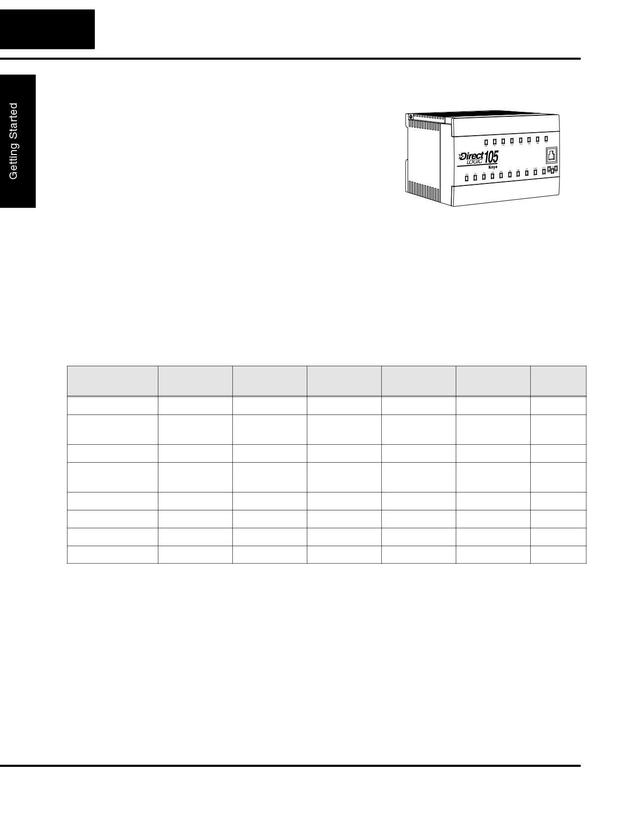
The DL105 Micro PLC family is a versatile
product line that provides a wide variety of
features in a very compact footprint. The
PLCs are small, yet offer many features
usually found in larger, more expensive
systems. These include removeable
connectors, RS-232C communication
port, and +24V auxiliary power supply.
The DL105
The DL105 Micro PLC family includes eight different versions. All have the same
Micro PLC Family
appearance and CPU performance. The CPU offers the same instruction set as our
popular DL230 CPU, plus several more instructions specifically designed for
machine control applications. All DL105 PLCs have an RS-232C communications
port, and the AC-powered versions have an auxiliary +24V output. Units with DC
inputs have selectable high-speed input features on four input points. Units with DC
outputs offer selectable pulse output capability on the first two output points. All
DL105 Micro PLCs offer a large amount of program memory, a substantial
instruction set and advanced diagnostics. Details of these features and more are
covered in Chapter 4, CPU Specifications and Operation. The eight types of DL105
Micro PLCs provide a variety of Input/Output choices, listed in the following table.
DL105
Discrete
Discrete
External
Auxiliary
High-Speed
Pulse
Part Number
Input Type
Output Type
Power
24V Output
Input
Output
F1-130AR
AC
Relay
94-240 VAC
Yes
No
No
F1-130DR/
DC
Relay
94-240 VAC
Yes
Yes
No
F1-130DR-CE*
F1-130AD
AC
DC
94-240 VAC
Yes
No
Yes
F1-130DD/
DC
DC
94-240 VAC
Yes
Yes
Yes
F1-130DD-CE*
F1-130AA
AC
AC
94-240 VAC
Yes
No
No
F1-130DA
DC
AC
94-240 VAC
Yes
Yes
No
F1-130DR-D
DC
Relay
10-30 VDC
No
Yes
No
F1-130DD-D
DC
DC
10-30 VDC
No
Yes
Yes
* The “-CE” versions look and function the same as the standard versions but are manufactured to comply with CE standards.
Programming Methods
Two programming methods are available: RLL (Relay Ladder Logic) and RLLPLUS
Stage programming RLLPLUS combines the added feature of flow chart
programming (stage) to the standard RLL language. Both the DirectSOFT32
programming package and the handheld programmer support RLLPLUS as well as
standard RLL instructions.
DirectSOFT32
The DL105 Micro PLC can be programmed with one of the most advanced
Programming for
programming packages in the industry
--DirectSOFT32, a Windows-based
Windows
software package that supports familiar features such as cut-and-paste between
applications, point-and-click editing, viewing and editing multiple application
programs at the same time, etc.
DL105 PLC User Manual, 2nd Edition, Rev. A
1-5
Getting Started
DirectSOFT32 universally supports the DirectLOGIC CPU families. This means
you can use the full version of DirectSOFT32 to program DL105, DL205, DL305,
DL405 or any new CPUs we may add to our product line. (Upgrade software may be
required for new CPUs as they become available.) With the introduction of the
DL105, we are also offering a low-cost DL105-only version of DirectSOFT32 to
make it even more affordable for new customers. A separate manual discusses
DirectSOFT32 programming software.
Handheld
All DL105 Micro PLCs have a built-in programming port for use with the handheld
Programmer
programmer (D2-HPP), the same programmer used with the DL205 family. The
handheld programmer can be used to create, modify and debug your application
program. A separate manual discusses the Handheld Programmer.
I/O Quick Chart Selection
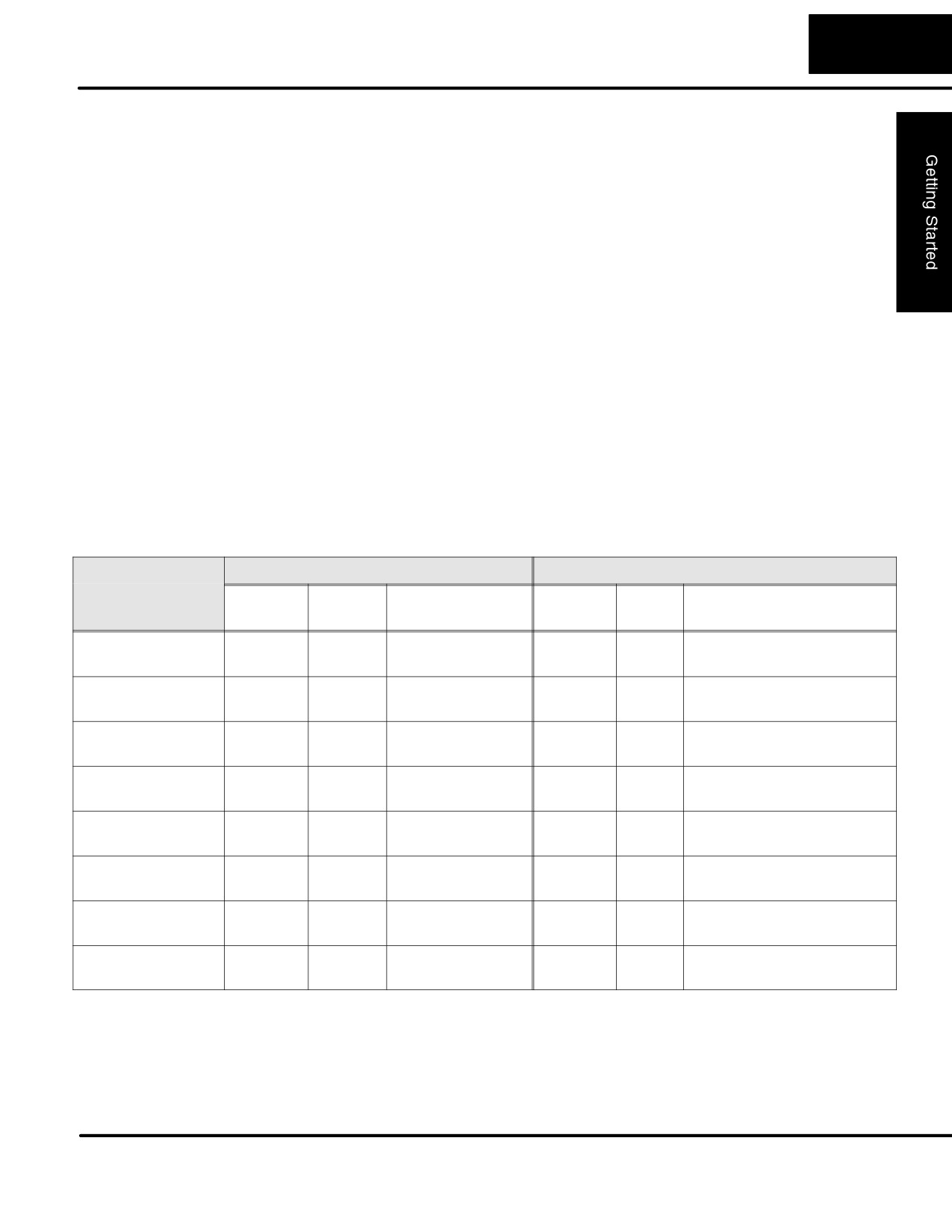
The eight versions of the DL105 have Input/Output circuits which can interface to a
wide variety of field devices. In several instances a particular Input or Output circuit
can interface to either DC or AC voltages, or both sinking and sourcing circuit
arrangements. Check this chart carefully to find the proper DL105 Micro PLC to
interface to the field devices in your application.
DL105
INPUTS
OUTPUTS
Part Number
I/O type /
Sink /
Voltage Ranges
I/O type /
Sink /
Voltage / Current
commons
Source
commons
Source
Ratings
F1-130AR
AC / 3
-
80 - 132 VAC
Relay / 4
Sink or
12 - 30 VDC, 7A *
90 - 150 VDC
Source
12 - 250 VAC, 7A *
F1-130DR/
DC / 3
Sink or
10 - 26.4 VDC
Relay / 4
Sink or
12 - 30 VDC, 7A *
F1-130DR-CE***
Source
21.6 - 26.4 VAC
Source
12 - 250 VAC, 7A *
F1-130AD
AC / 3
-
80 - 132 VAC
DC / 1 **
Sink
5 - 30 VDC, 0.3A (Y0-Y1)
90 - 150 VDC
5 - 30 VDC, 0.6A (Y3-Y7)
F1-130DD/
DC / 3
Sink or
10 - 26.4 VDC
DC / 1 **
Sink
5 - 30 VDC, 0.3A (Y0-Y1)
F1-130DD-CE***
Source
21.6 - 26.4 VAC
5 - 30 VDC, 0.6A (Y3-Y7)
F1-130AA
AC / 3
-
80 - 132 VAC
AC / 4
-
20 - 140 VAC, 47 - 63 Hz
90 - 150 VDC
1.7A *
F1-130DA
DC / 3
Sink or
10 - 26.4 VDC
AC / 4
-
20 - 140 VAC, 47 - 63 Hz
Source
21.6 - 26.4 VAC
1.7A *
F1-130DR-D
DC / 3
Sink or
10 - 26.4 VDC
Relay / 4
Sink or
12 - 30 VDC, 7A *
Source
21.6 - 26.4 VAC
Source
12 - 250 VAC, 7A *
F1-130DD-D
DC / 3
Sink or
10 - 26.4 VDC
DC / 1 **
Sink
5 - 30 VDC, 0.3A (Y0-Y1)
Source
21.6 - 26.4 VAC
5 - 30 VDC, 0.6A (Y3-Y7)
* Subject to temperature derating chart. See Chapter 2 Specifications for your particular DL105 version.
** DC outputs have one electrical common, but it is accessible at three terminals on the output connector.
*** The “-CE” versions look and function the same as the standard versions but are manufactured to comply with CE standards.
DL105 PLC User Manual, 2nd Edition, Rev. A
1-6
Getting Started
Quick Start for PLC Checkout and Programming
If you have experience with PLCs, or if you just want to setup a quick example, this
example is for you! This example is not intended to tell you everything you need to
start-up your system, warnings and helpful tips are in the rest of the manual. It is only
intended to give you a general picture of what you will need to do to get your system
powered-up.
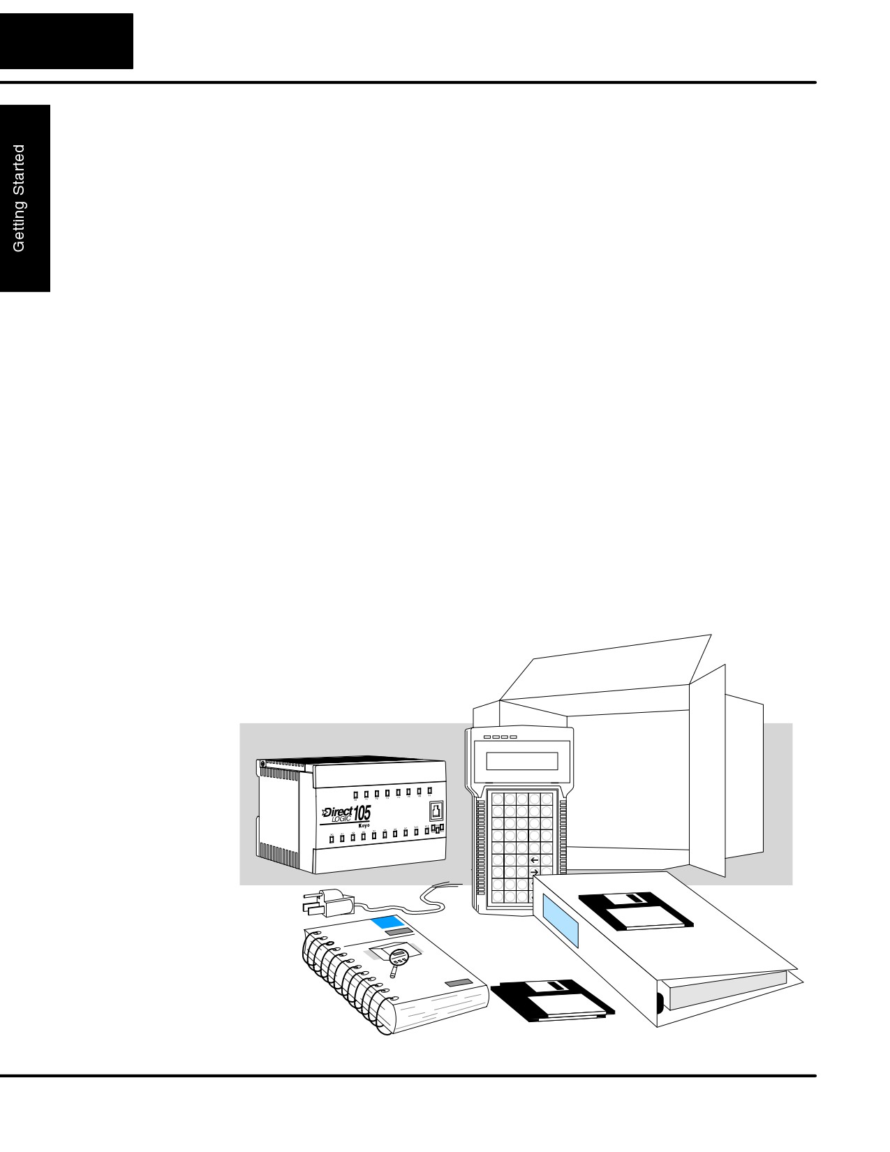
Step 1: Unpack the DL105 Equipment
Unpack the DL105 equipment and verify you have the parts necessary to build this
demonstration system. The recommended components are:
S DL105 Micro PLC
S AC power cord for AC-powered units
S F1-04SIM input simulator, or toggle switches (see Step 2 on next page).
S Hook-up wire, 16-20 AWG
S DL105 User Manual (this manual)
S A small screwdriver, regular or #2 Philips type
You will need at least one of the following programming options:
S DirectSOFT32 Programming Software, DirectSOFT32 Manual, and a
programming cable (connects the DL105 to a personal computer),or
S D2-HPP Handheld Programmer (comes with programming cable), and
the Handheld Programmer Manual
DL105 PLC User Manual, 2nd Edition, Rev. A
1-7
Getting Started
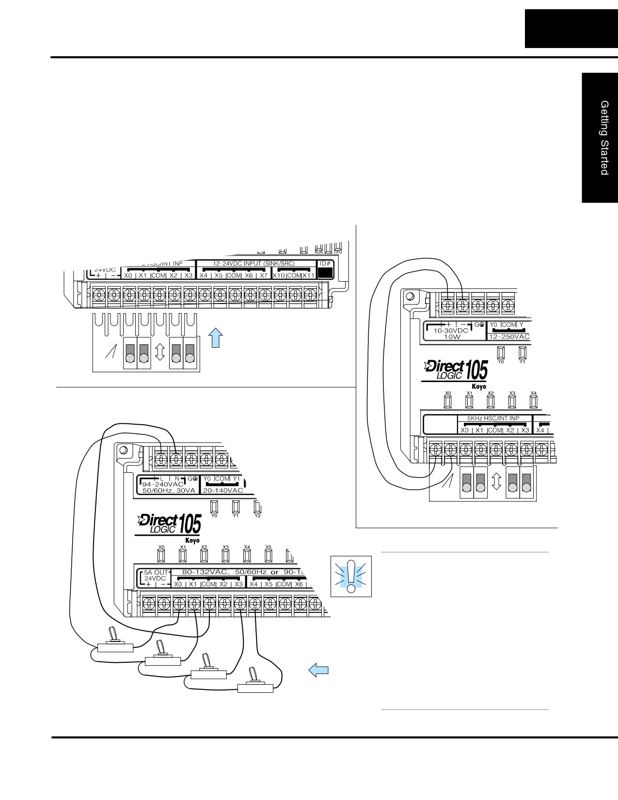
Step 2: Connect Switches to Input Terminals
To finish this quick-start exercise or study other examples in this manual, you’ll need
to connect some input switches as shown below. For most models, the F1-04SIM
Input Simulator is a quick way to install four switches on inputs X0 - X3. DC-powered
units will require routing DC power to the simulator as shown. We recommend using
one of the models compatible with the input simulator as you learn the DL105.
However, you may wire individual toggle switches to AC-powered units as shown, as
long as you follow the instructions in the accompanying WARNING note.
F1-130DR-D, F1-130DD-D
F1-130DR/F1-130DR-CE,
(DC input versions)
(DC-powered versions)
F1-130DD/F1-130DD-CE,
F1-130DA
Slide simulator under
ON
left-most terminals
FACTS
and tighten screws.
engineering
F1-04SIM
OFF
F1-130AR, F1-130AD, F1-130AA
(AC input versions, 120VAC only)
ON
FACTS
engineering
F1-04SIM
OFF
WARNING: DO NOT wire the
toggle switches as shown to
240VAC-powered units. The
discrete inputs will only accept
120VAC nominal. Also, remove
power and unplug the DL105 when
wiring the switches. Only use
UL-approved switches rated for at
least 250VAC, 1A. Firmly mount
the switches before using.
NEVER use the input simulator on
these units with AC-type discrete
inputs.
Toggle Switches, UL Listed
DL105 PLC User Manual, 2nd Edition, Rev. A
1-8
Getting Started
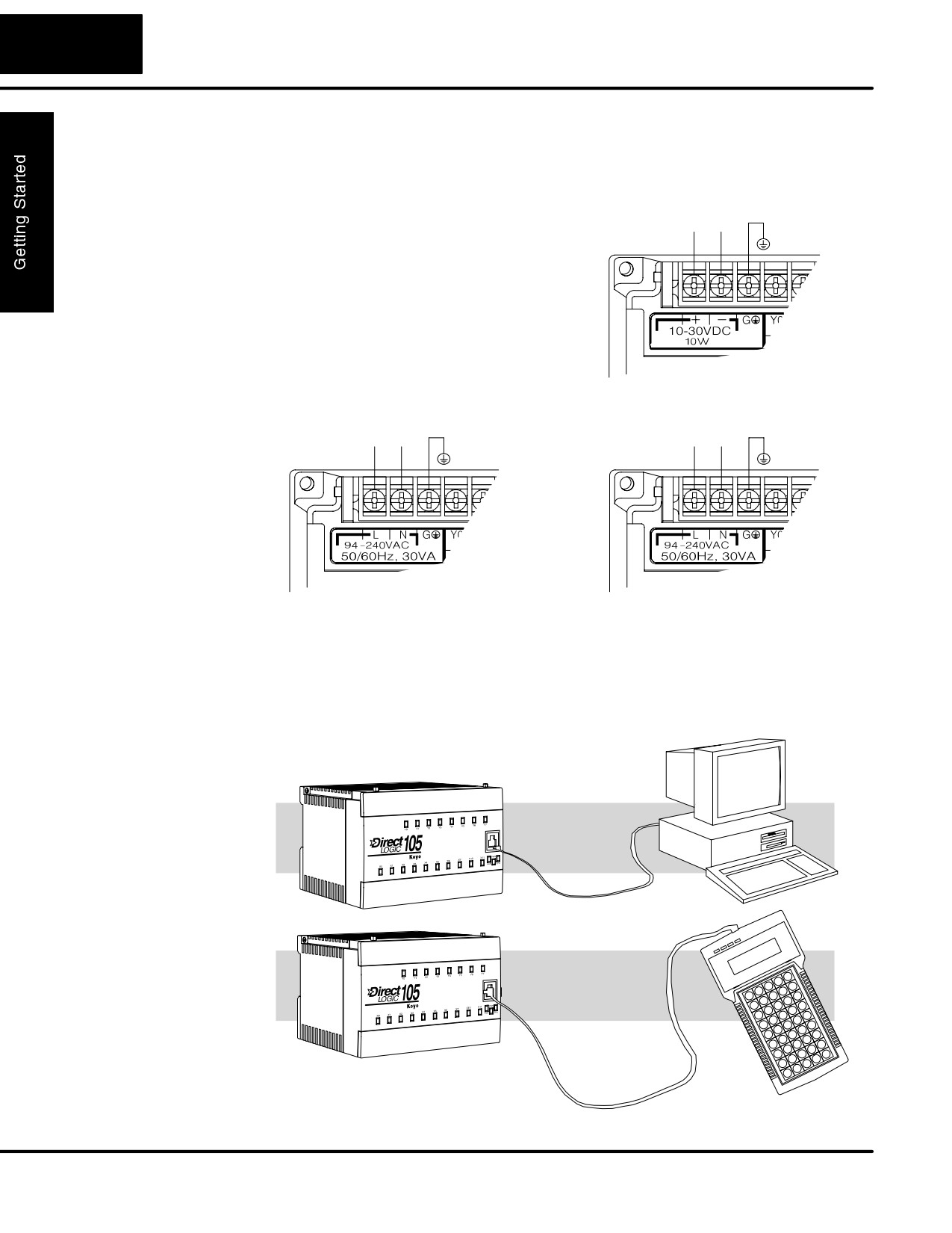
Step 3: Connect the Power Wiring
Connect the power input wiring for the
12/24 VDC Power Input
version DL105 you have. Observe all
10 - 30 VDC
precautions stated earlier in this manual.
+
-
G
For more details on wiring, see Chapter 2
on Installation, Wiring, and Specifications.
When the wiring is complete, close the
connector covers. Do not apply power at
this time.
110/220 VAC Power Input
125 VDC Power Input
94 - 240 VAC
100 - 240 VDC
L
N
G
+
-
G
Step 4: Connect the Programming Device
Most programmers will use DirectSOFT32 programming software, installed on a
personal computer. Or, you may need the portability of the Handheld Programmer.
Both devices will connect the COM1 port of the DL105 via the appropriate cable.
Use cable part no.
D2-DSCBL
(cable comes with HPP)
For replacement
cable, use part no.
DV-1000CBL
DL105 PLC User Manual, 2nd Edition, Rev. A
1-9
Getting Started
Step 5: Switch on the System Power
Apply power to the system and ensure the PWR indicator on the DL105 is on. If not,
remove power from the system and check all wiring and refer to the troubleshooting
section in Chapter 8 for assistance.
Step 6: Initialize Scratchpad Memory
It’s a good precaution to always clear the system memory (scratchpad memory) on a
new DL105. When a unit has been without power for several days, the system RAM
contents may have been corrupted and will require initialization.
S In DirectSOFT32, select the PLC menu, then Setup, then Initialize
Scratchpad. For additional information, see the DirectSOFT32 Manual.
S For the Handheld Programmer, use the AUX key and execute AUX 54.
For additional information, see the Handheld Programmer Manual.
Step 7: Enter a Ladder Program
At this point, DirectSOFT32 programmers need to refer to the Quick Start Tutorial in
the DirectSOFT32 Manual. There you will learn how to establish a communications
link with the DL105 PLC, change CPU modes to Run or Program, and enter a
program.
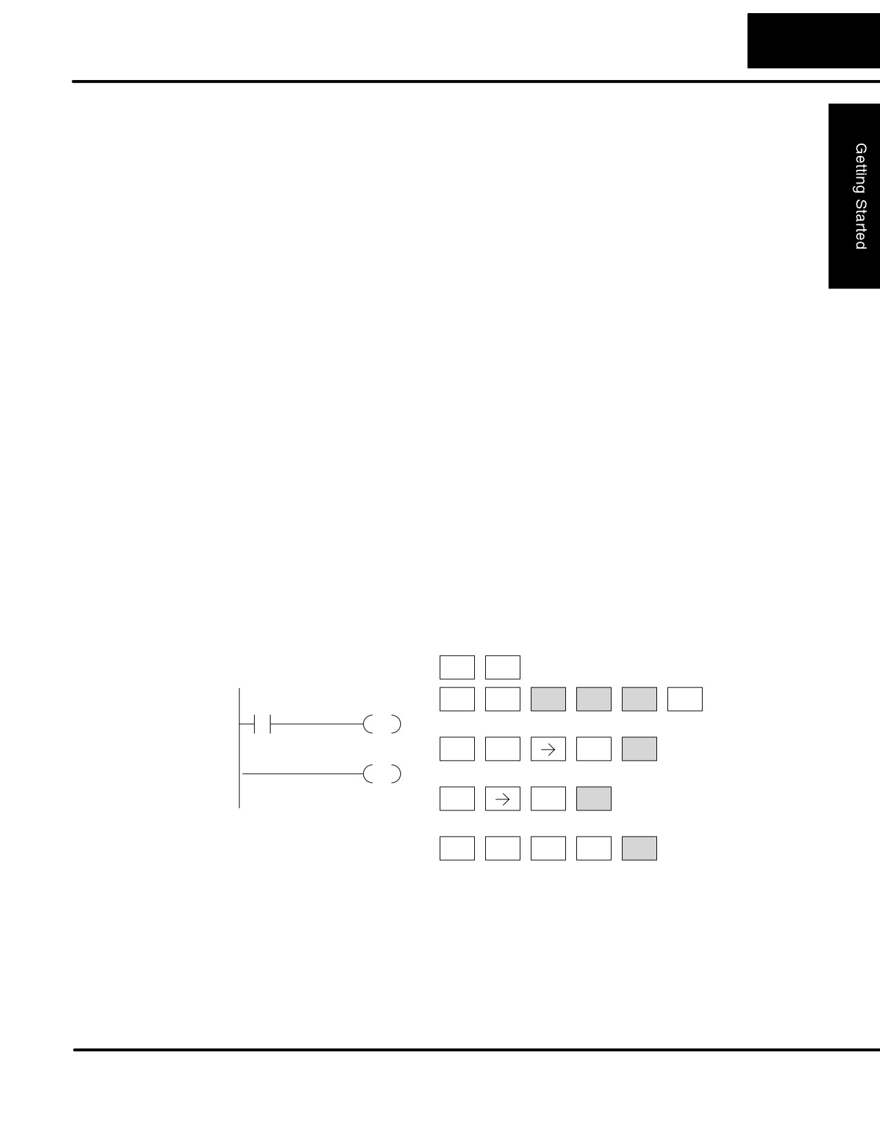
If you are learning how to program with the Handheld Programmer, make sure the
CPU is in Program Mode (the RUN LED on the front of the DL105 should be off.) If
the RUN LED is on, use the MODE key on the Handheld Programmer to put the PLC
in Program Mode. Enter the following keystrokes on the Handheld Programmer.
Clear the Program
Equivalent DirectSOFT32 display
CLR
CLR
C
E
AUX
ENT
ENT
CLR
X0
Y0
2
4
OUT
$
A
Move to the first
NEXT
ENT
STR
0
address and enter
X0 contact
END
GX
A
Enter output Y0
ENT
OUT
0
E
N
D
Enter the END
SHFT
ENT
4
TMR
3
statement
After entering the simple example program put the PLC in Run mode by using the
Mode key on the Handheld Programmer.
The RUN indicator on the PLC will illuminate indicating the CPU has entered the Run
mode. If not, repeat this step, ensuring the program is entered properly or refer to the
troubleshooting guide in chapter 8.
After the CPU enters the run mode, the output status indicator for Y should follow the
switch status on input channel X0. When the switch is on, the output will be on.
DL105 PLC User Manual, 2nd Edition, Rev. A
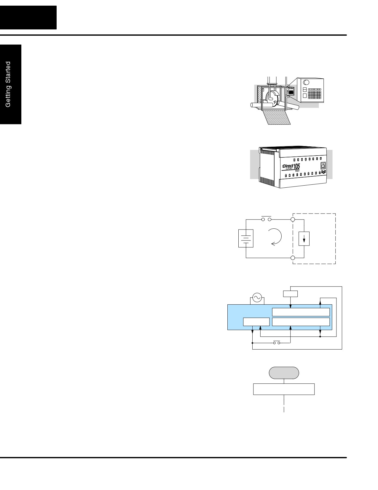
1-10
Getting Started
Steps to Designing a Successful System
Step 1:
Always make safety the first priority in any
Review the
system design. Chapter
2 provides
Installation
several guidelines that will help you
Guidelines
design a safer, more reliable system. This
chapter also includes wiring guidelines for
the various versions of the DL105 PLC.
Step 2:
The PLC is the heart of your automation
Understand the
system. Make sure you take time to
PLC Setup
understand the various features and setup
Procedures
requirements.
Step 3:
There are many considerations involved
PLC
Input
Review the I/O
when you select your I/O type and field
Selection Criteria
devices. Take time to understand how the
various types of sensors and loads can
+
Input
affect your choice of I/O type.
Sensing
-
Common
Step 4:
It is important to understand the various
AC
Power
Choose a System
system design options that are available
Loads
Wiring Strategy
before wiring field devices and field-side
power supplies to the Micro PLC.
DL105
Power Input
PLC
8 Outputs
Commons
+24 VDC
10 Inputs Commons
+
-
Step 5:
Before you begin to enter a program, it is
Understand the
very helpful to understand how the DL105
Power up
system processes information. This
System Operation
involves not only program execution
Initialize hardware
steps, but also involves the various modes
of operation and memory layout
characteristics.
DL105 PLC User Manual, 2nd Edition, Rev. A
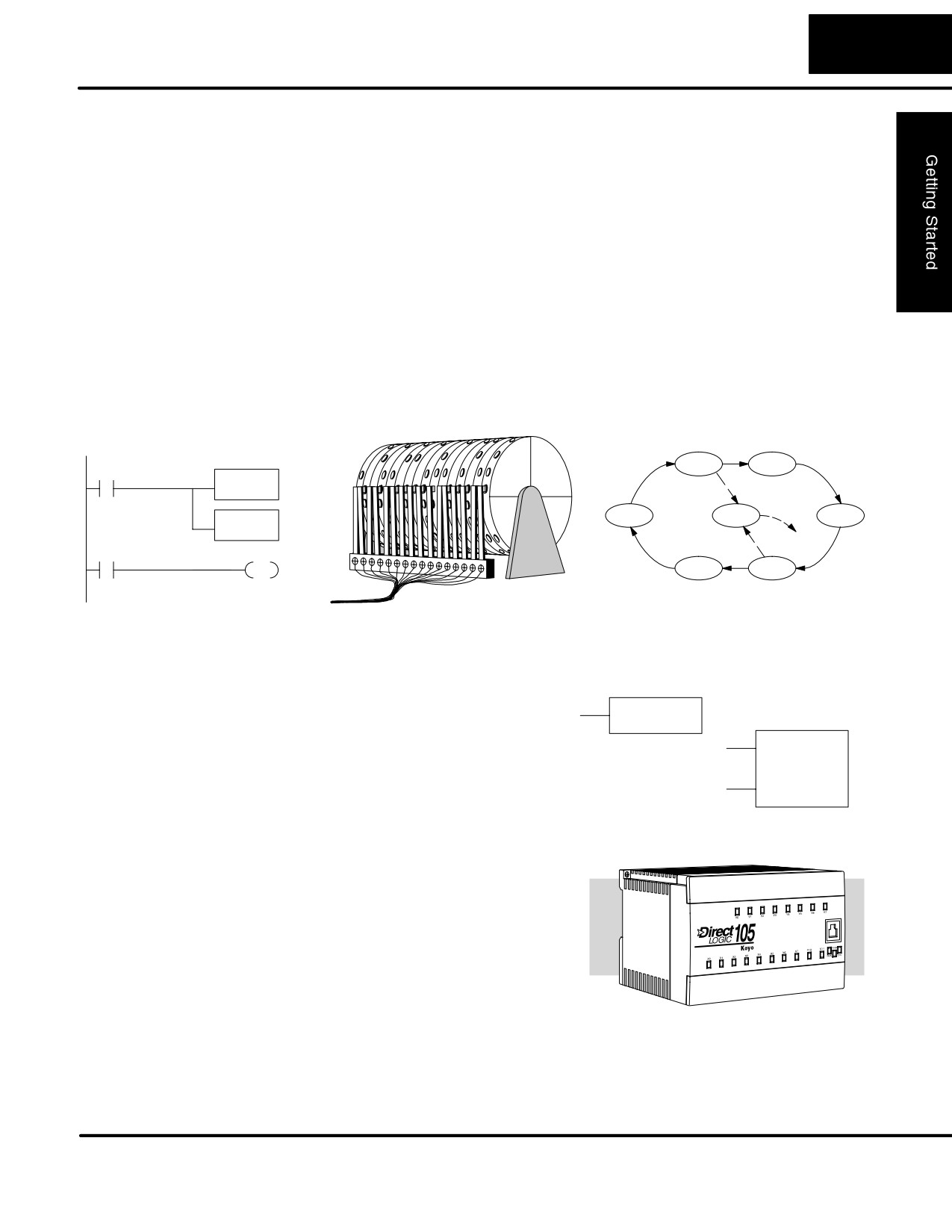
1-11
Getting Started
Step 6:
The DL105 PLC instruction set provides for three main approaches to solving the
Review the
application program, depicted in the figure below.
Programming
Concepts
S RLL diagram-style programming is the best tool for solving boolean logic
and general CPU register/accumulator manipulation. It includes dozens
of instructions, which will also be needed to augment drums and stages.
S The Timer/Event Drum Sequencer features up to 16 steps and offers
both time and/or event-based step transitions. The EDRUM instruction
is best for a repetitive process based on a single series of steps.
S Stage programming (also called RLLPlus) is based on state-transition
diagrams. Stages divide the ladder program into sections which
correspond to the states in a flow chart you draw for your process.
Standard RLL Programming
Timer/Event Drum Sequencer
Stage Programming
(see Chapter 5)
(see Chapter 6)
(see Chapter 7)
Push-UP
RAISE
X0
LDD
V1076
DOWN
LIGHT
UP
CMPD
K309482
SP62
Y0
Push-
OUT
LOWER
DOWN
After reviewing the programming concepts above, you’ll be equipped with a variety
of tools to write your application program.
Step 7:
Once you have installed the Micro PLC
TMR
T1
Choose the
and understand the main programming
K30
Instructions
concepts, you can begin writing your
CNT
CT3
application program. At that time you will
K10
begin to use one of the most powerful
instruction sets available in a small PLC.
Step 8:
Sometimes equipment failures occur
Understand the
when we least expect it. Switches fail,
Maintenance and
loads short and need to be replaced, etc.
Troubleshooting
In most cases, the majority of the
Procedures
troubleshooting and maintenance time is
spent trying to locate the problem. The
DL105 Micro PLC has many built-in
features such as error codes that can help
you quickly identify problems.
DL105 PLC User Manual, 2nd Edition, Rev. A
1-12
Getting Started
Questions and Answers about DL105 Micro PLCs
Q. What is the instruction set like?
A. The instruction set is very close to our popular DL230 CPU. However, there are
significant additions, such as the drum instruction and High-Speed I/O capability.
Q. Do I have to buy the full DirectSOFT32 programming package to program the DL105?
A. No. We offer a DL105-specific version of DirectSOFT32 that’s very affordable.
Q. Is the DL105 networkable or expandable?
A. No, the DL130 series is stand-alone PLCs. However, our DL205 system is
expandable and networkable (with DL240 CPU), yet very compact and affordable.
Q. Does the DL105 have motion control capability?
A. Yes. The High-Speed I/O features offer either encoder inputs with high-speed
counting and presets with interrupt, or a pulse/direction output for stepper control.
Three types of motion profiles are available, which are explained in Chapter 3.
Q. Are the ladder programs stored in a removable EPROM?
A. The DL105 contains a non-removable EEPROM for program storage, which may
be written and erased thousands of times. You may transfer programs to/from
DirectSOFT32 on a PC, or the HPP (which does support a removable EEPROM).
Q. Does the DL105 contain fuses for its outputs?
A. There are no output circuit fuses. Therefore, we recommend fusing each channel,
or fusing each common. See Chapter 2 for I/O wiring guidelines.
Q. Is the DL105 Micro PLC U.L.R approved?
A. The Micro PLC has been designed to meet the requirements of UL (Underwriters’
Laboratories, Inc.), CSA (Canadian Standards Association), and CUL (Canadian
Underwriters’ Laboratories, Inc.). Approvals are pending the completion of testing.
Q. Does the DL105 Micro PLC comply with European Union (EU) Directives?
A. Currently, the following four versions carry the CE label, indicating compliance
with European Union Directives: The F1-130DR-CE and F1-130DD-CE AC
powered versions and the F1-130DD-D and F1-130DR-D DC powered versions.
See Appendix E for further information on EU Directives.
DL105 PLC User Manual, 2nd Edition, Rev. A
1-13
Getting Started
Q. Which devices can I connect to the Com1 port of the DL105?
A. The port is RS-232C, fixed at 9600 baud, and uses the proprietary K-sequence
protocol. The port communicates with the following devices:
S DV-1000 Data Access Unit or Optimation Operator interface panels
S DirectSOFT32 (running on a personal computer)
S D2-HPP handheld programmer
S Other devices which communicate via K-sequence protcol should work
with the DL105 Micro PLC. Contact the vendor for details.
Q. Can the DL105 accept 5VDC inputs?
A. No, 5 volts is lower than the DC input ON threshold. However, many TTL logic
circuits can drive the inputs if they are wired as open collector (sinking) inputs. See
Chapter 2 for I/O wiring guidelines.
DL105 PLC User Manual, 2nd Edition, Rev. A
2
Installation, Wiring,
and Specifications
In This Chapter
Ċ Safety Guidelines
Ċ Orientation to DL105 Front Panel
Ċ Mounting Guidelines
Ċ Wiring Guidelines
Ċ System Wiring Strategies
Ċ Wiring Diagrams and Specifications
Ċ Glossary of Specification Terms
2-2
Installation, Wiring, and Specifications
Safety Guidelines
NOTE: Products with CE marks perform their required functions safely and adhere
to relevant standards as specified by EC directives provided they are used
according to their intended purpose and that the instructions in this manual are
adhered to. The protection provided by the equipment may be impaired if this
equipment is used in a manner not specified in this manual. A listing of our
WARNING: Providing a safe operating environment for personnel and equipment is
your responsibility and should be your primary goal during system planning and
installation. Automation systems can fail and may result in situations that can cause
serious injury to personnel or damage to equipment. Do not rely on the automation
system alone to provide a safe operating environment. You should use external
electromechanical devices, such as relays or limit switches, that are independent of
the PLC application to provide protection for any part of the system that may cause
personal injury or damage.
Every automation application is different, so there may be special requirements for
your particular application. Make sure you follow all national, state, and local
government requirements for the proper installation and use of your equipment.
Plan for Safety
The best way to provide a safe operating environment is to make personnel and
equipment safety part of the planning process. You should examine every aspect of
the system to determine which areas are critical to operator or machine safety. If you
are not familiar with PLC system installation practices, or your company does not
have established installation guidelines, you should obtain additional information
from the following sources.
S NEMA — The National Electrical Manufacturers Association, located in
Washington, D.C., publishes many different documents that discuss
standards for industrial control systems. You can order these
publications directly from NEMA. Some of these include:
ICS 1, General Standards for Industrial Control and Systems
ICS 3, Industrial Systems
ICS 6, Enclosures for Industrial Control Systems
S NEC — The National Electrical Code provides regulations concerning
the installation and use of various types of electrical equipment. Copies
of the NEC Handbook can often be obtained from your local electrical
equipment distributor or your local library.
S Local and State Agencies — many local governments and state
governments have additional requirements above and beyond those
described in the NEC Handbook. Check with your local Electrical
Inspector or Fire Marshall office for information.
Three Levels of
The publications mentioned provide many ideas and requirements for system
Protection
safety. At a minimum, you should follow these regulations. Also, you should use the
following techniques, which provide three levels of system control.
S Orderly system shutdown sequence in the PLC control program
S Mechanical disconnect for output module power
S Emergency stop switch for disconnecting system power
DL105 PLC User Manual, 2nd Edition, Rev. A
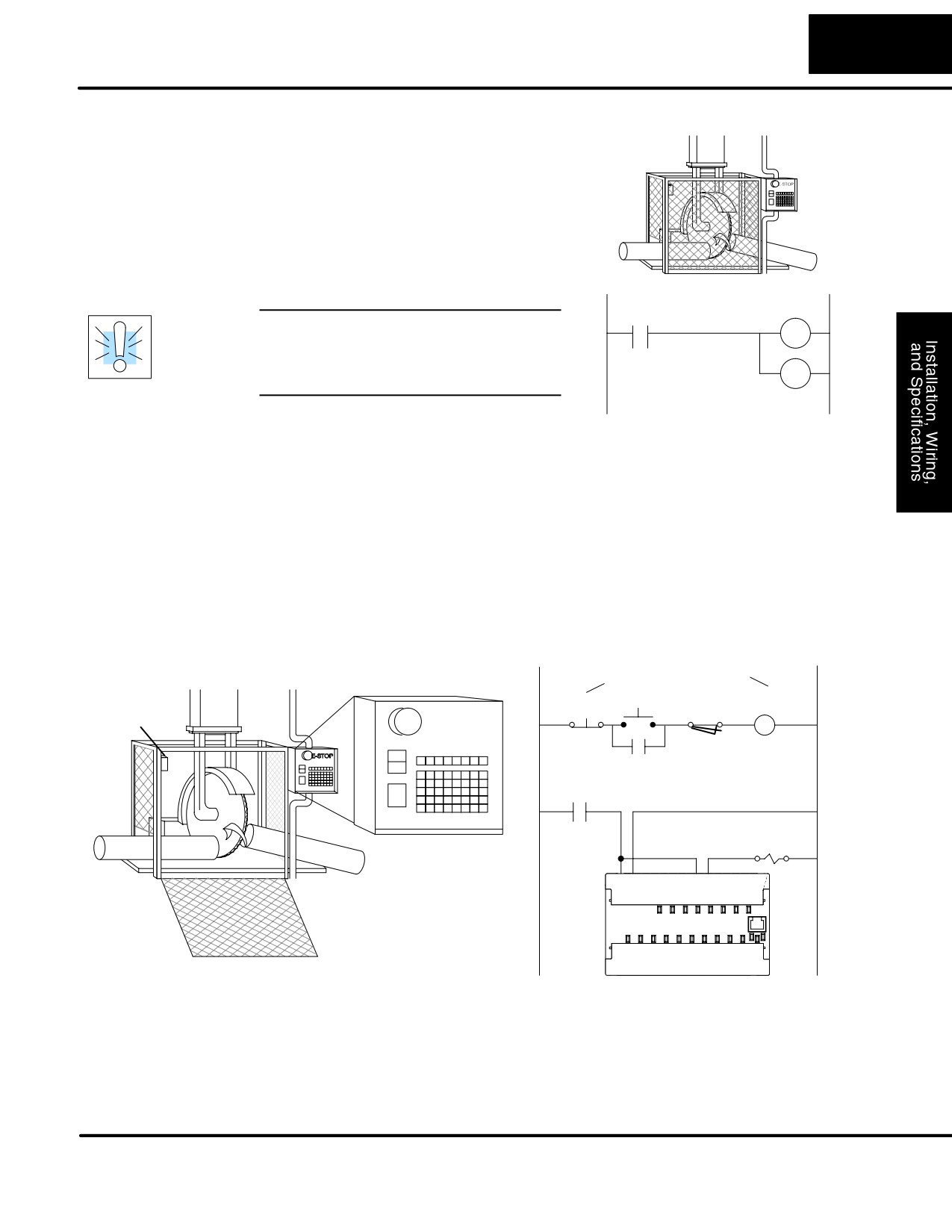
2-3
Installation, Wiring, and Specifications
Orderly System
The first level of fault detection is ideally
Shutdown
the PLC control program, which can
identify machine problems. You must
analyze your application and identify any
shutdown sequences that must be
performed. These types of problems are
usually things such as jammed parts, etc.
that do not pose a risk of personal injury
or equipment damage.
Turn off
Jam
Saw
Detect
WARNING: The control program must
RST
not be the only form of protection for any
problems that may result in a risk of
RST
personal injury or equipment damage.
Retract
Arm
System Power
You should also use electromechanical devices, such as master control relays
Disconnect
and/or limit switches, to prevent accidental equipment startup at an unexpected
time. These devices should be installed in such a manner to prevent any machine
operations from occurring.
For example, if the machine has a jammed part the PLC control program can turn off
the saw blade and retract the arbor. However, since the operator must open the
guard to remove the part, you should also include a bypass switch that disconnects
all system power any time the guard is opened.
Emergency Stop
The machinery must provide a quick manual method of disconnecting all system
power. The disconnect device or switch must be clearly labeled “Emergency Stop”.
Use EĆStop and Master Relay
Power On
Guard
Master
E STOP
Relay
Guard Limit Switch
Limit
Emergency
Stop
Master Relay Contacts
Master Relay Contacts
To disconnect
To disconnect PLC
Saw
PLC Power
output circuitry
Arbor
After an Emergency shutdown or any other type of power interruption, there may be
requirements that must be met before the PLC control program can be restarted. For
example, there may be specific register values that must be established (or
maintained from the state prior to the shutdown) before operations can resume. In
this case, you may want to use retentive memory locations, or include constants in
the control program to ensure a known starting point.
DL105 PLC User Manual, 2nd Edition, Rev. A
2-4
Installation, Wiring, and Specifications
Orientation to DL105 Front Panel
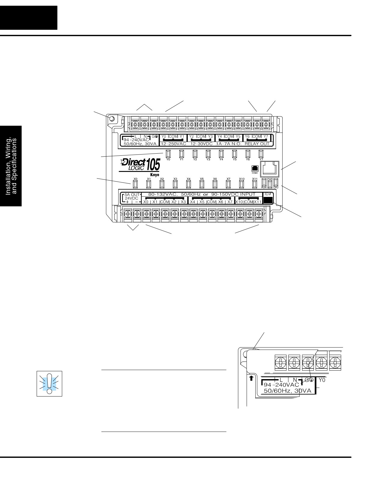
All connections, indicators, and labels on the DL105 Micro PLCs are located on its
front panel. Please refer to the drawing below.
External Power Input
Discrete Output Terminals
Output Circuit Power Input
(for DC Output versions only)
Mounting hole (1 of 2)
Output Status Indicators
Communications Port
Input Status Indicators
Run, Power, CPU
Indicators
ID# Area
Auxiliary Supply Terminals
Discrete Input Terminals
The upper connector accepts external power connections on the left-most
terminals. The remainder of the terminals accept wires for the eight output points
and their commons. On DC output versions, the end terminal on the right accepts
power for the output stage. In many applications the external power to the Micro PLC
also powers the loads and output circuit, so this terminal block groups them together.
The lower connector delivers the internal +24VDC auxiliary supply output on the two
left-most terminals (AC-powered units only). On DC-powered units, the terminals
are not used. The remaining terminals accept wires for the ten discrete inputs and
their commons. In many applications the auxiliary +24VDC output also powers the
input circuit, so this terminal block groups them together.
Accessing the
To access the terminals just pull forward
Pull Here (terminal block cover, 1 of 2)
I/O Terminals
on the corner of the terminal cover where it
is marked “pull”, as shown to the right.
After exposing the connector block, it may
ÉÉÉÉÉÉÉÉÉ
be removed from the unit if desired.
ÉÉÉÉÉÉÉÉ
ÉÉÉÉÉÉÉÉ
WARNING: For some applications, field
device power may still be present on the
ÉÉÉÉÉÉÉ
P
terminal block even though the Micro PLC
É
ÉÉÉÉÉ
is turned off. To minimize the risk of
L
L
ÉÉÉÉÉÉ
electrical shock, check all field device
power before you expose or remove either
connector. Be sure to leave the covers
normally closed.
DL105 PLC User Manual, 2nd Edition, Rev. A
2-5
Installation, Wiring, and Specifications
Protective Sheet
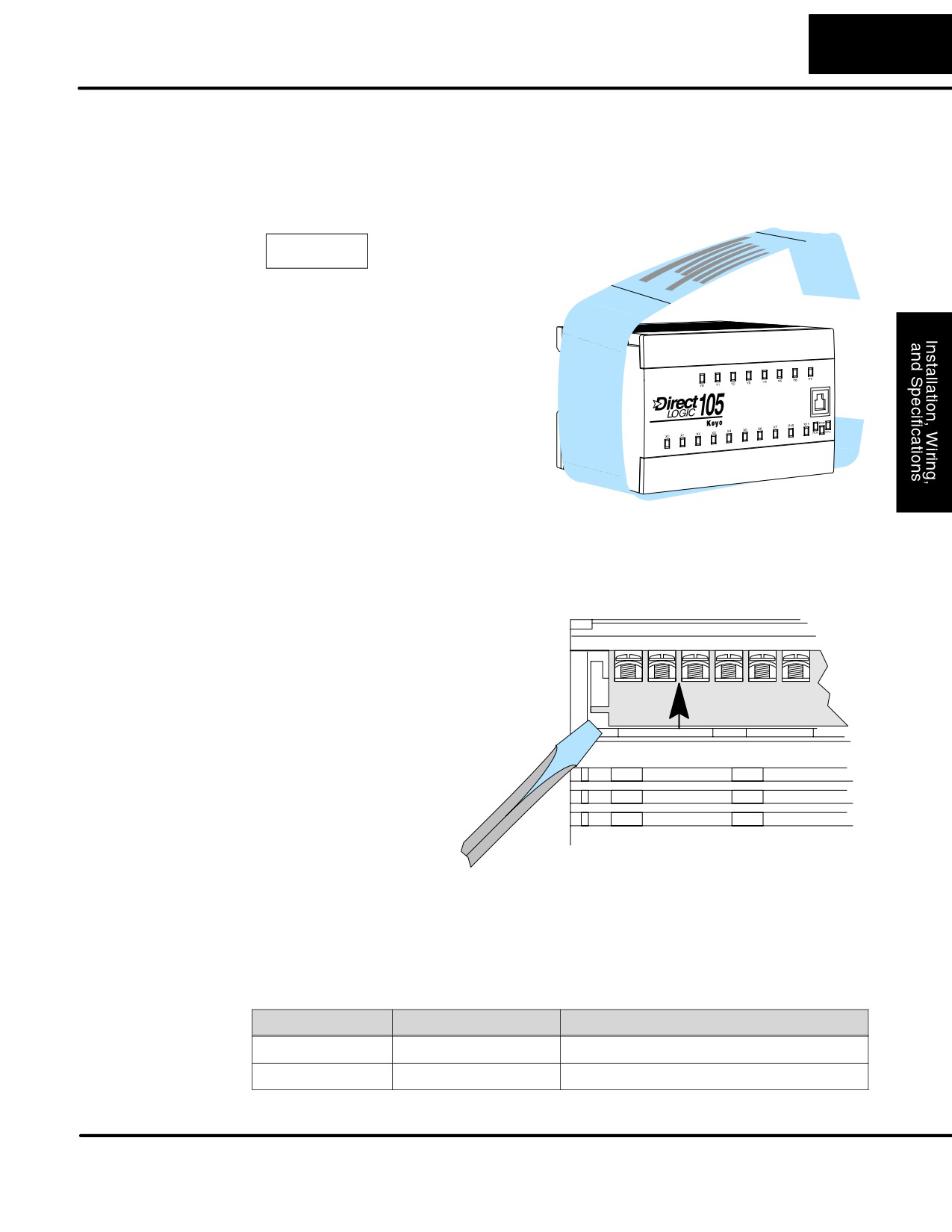
Some machine fabrication environments may accidentally cause conductive debris
for DL105 Vents
to fall through the DL105 cooling vents and into the unit. All DL105 units come with a
protective sheet wrapped around the unit, covering the cooling vents. However, it
must be removed before electrical operation. Just unfasten the sheet on the right
side of the unit. The instructions are reprinted below for your reference.
CAUTION
1. DO NOT REMOVE THIS PROTECTIVE
SHEET until installation and wiring are completed.
2. REMOVE THIS SHEET before operation
to enable heat to escape for proper cooling.
Connector
The input and output terminal block connectors on the DL105 are identical. The
Removal
connectors are designed for easy removal with just a small screwdriver. The drawing
below shows the procedure for removal at one end. You’ll need to work at both ends
of the connector, so the ends move upwards approximately together.
Connector Removal
1. Insert the screwdriver tip straight
into the opening at the corner of the
connector as shown.
2. Pry screwdriver tip so connector
moves upward in direction of arrow.
The two terminal block connectors on DL105 PLCs have regular screw terminals,
which will accept either standard or #2 Philips screwdriver tips. You can insert one 14
AWG wire under a terminal, or two 16 AWG wires (one on each side of the screw). Be
careful not to overtighten; maximum torque is 6 inch/ounces.
Spare terminal block connectors and connector covers may be ordered by individual
part numbers:
Part Number
Qty Per Package
Description
F1-IOCON
4
DL105 I/O Terminal Block
F1-IOCVR
4
DL105 I/O Terminal Cover
DL105 PLC User Manual, 2nd Edition, Rev. A
2-6
Installation, Wiring, and Specifications
Mounting Guidelines
In addition to the panel layout guidelines, other specifications can affect the
definition and installation of a PLC system. Always consider the following:
S Environmental Specifications
S Power Requirements
S Agency Approvals
S Enclosure Selection and Component Dimensions
Unit Dimensions
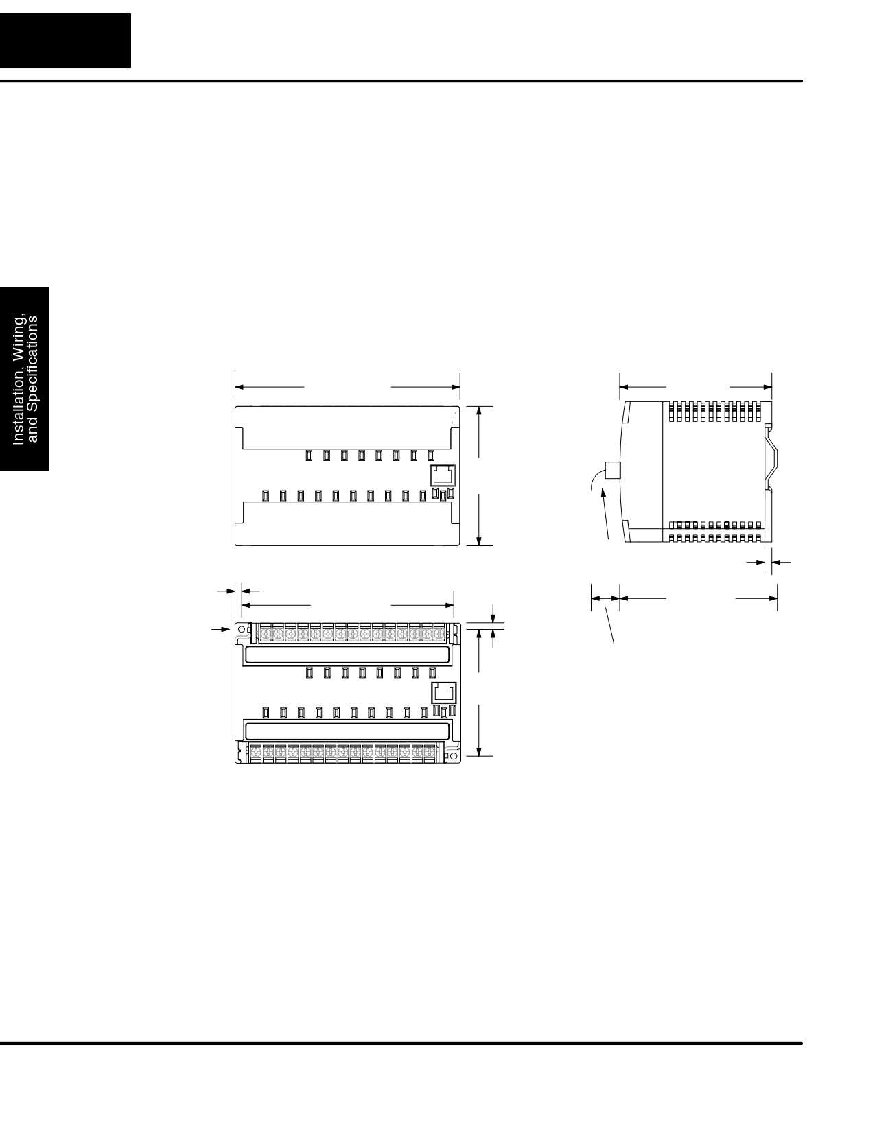
The following diagram shows the outside dimensions and mounting hole locations
for all versions of the DL105. Make sure you follow the installation guidelines to allow
proper spacing from other components.
5.12”
3.48”
129.9mm
88.3mm
3.16”
80.3mm
0.25” mounting tab
0.15”
6.4 mm
0.38mm
Cable
3.63”
4.82”
92.1mm
122.33mm
(DIN Rail)
2 holes, 0.150” dia,
0.15”
clearance for #6 screw
0.38mm
1.5” min. / 3” recommended
38.1 mm / 76.2mm
2.86”
72.64mm
Your selection of a proper enclosure is important to ensure safe and proper
Enclosures
operation of your DL105 system. Applications of DL105 systems vary and may
require additional features. The minimum considerations for enclosures include:
S Conformance to electrical standards
S Protection from the elements in an industrial environment
S Common ground reference
S Maintenance of specified ambient temperature
S Access to equipment
S Security or restricted access
S Sufficient space for proper installation and maintenance of equipment
DL105 PLC User Manual, 2nd Edition, Rev. A
2-7
Installation, Wiring, and Specifications
Panel Layout &
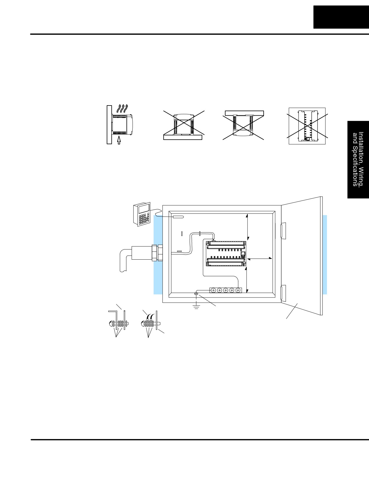
There are many things to consider when designing the panel layout. The following items
Clearances
correspond to the diagram shown. Note: there may be additional requirements,
depending on your application and use of other components in the cabinet.
1.
Mount the bases horizontally as shown below to provide proper ventilation.
You cannot mount the DL105 units vertically, upside down, or on a flat
horizontal surface. If you place more than one unit in a cabinet, there must
be a minimum of 7.2” (183mm) between the units.
ÉÉOK
ÇÇÇÇÇ
ÍÍÍÍÍ
ÉÉ
ÇÇÇÇÇ
Í
ÍÍÍ
ÉÉ
Í
ÍÍÍ
ÉÉ
ÇÇÇÇÇ
Í
ÍÍÍ
Airflow
ÉÉ
ÇÇÇÇÇ
ÍÍÍÍÍ
2.
Provide a minimum clearance of 2” (50mm) between the unit and all sides of
the cabinet. Note, remember to allow for any operator panels or other items
mounted in the door.
3.
There should also be at least 3” (78mm) of clearance between the unit and
any wiring ducts that run parallel to the terminals.
Temperature
Probe
Æ
2"
Á
50mm
DL105
min.
Micro PLC
Ã
Á
2"
Power
50mm
Source
min.
Ç
À
Á 2"
50mm
BUS Bar
min.
Ä
Å
Á
Panel
Ground Braid
Copper Lugs
Panel Ground
Earth Ground Terminal
Panel or
Note: there is a minimum of 2” (30mm)
Single Point
clearance between the panel door
or any devices mounted in the panel door
Ground
Star Washers
Star Washers
and the nearest DL105 component
Not to Scale
4. The ground terminal on the DL105 base must be connected to a single
point ground. Use copper stranded wire to achieve a low impedance.
Copper eye lugs should be crimped and soldered to the ends of the
stranded wire to ensure good surface contact.
5. There must be a single point ground (i.e. copper bus bar) for all devices in
the panel requiring an earth ground return. The single point of ground must
be connected to the panel ground termination. The panel ground
termination must be connected to earth ground. Minimum wire sizes, color
coding, and general safety practices should comply with appropriate
electrical codes and standards for your area.
DL105 PLC User Manual, 2nd Edition, Rev. A
2-8
Installation, Wiring, and Specifications
6. A good common ground reference (Earth ground) is essential for proper
operation of the DL105. One side of all control and power circuits and the
ground lead on flexible shielded cable must be properly connected to Earth
ground. There are several methods of providing an adequate common
ground reference, including:
a) Installing a ground rod as close to the panel as possible.
b) Connection to incoming power system ground.
7. Evaluate any installations where the ambient temperature may approach
the lower or upper limits of the specifications. If you suspect the ambient
temperature will not be within the operating specification for the DL105
system, measures such as installing a cooling/heating source must be
taken to get the ambient temperature within the range of specifications.
8. The DL105 systems are designed to be powered by 110 VAC , 220 VAC,
125 VDC or 24 VDC normally available throughout an industrial
environment. Isolation transformers and noise suppression devices are
not normally necessary, but may be helpful in eliminating/reducing
suspected power problems.
NOTE: If you are using other components in your system, make sure you refer to the
appropriate manual to determine how those units can affect mounting dimensions.
Agency Approvals
Some applications require agency approvals for particular components. The DL105
Micro PLC submission status for agency approval is listed below:
S UL (Underwriters’ Laboratories, Inc.)
pending (Apr., 1998)
S CSA (Canadian Standards Association)
pending (Apr., 1998)
S CUL (Canadian Underwriters’ Laboratories, Inc.) pending (Apr., 1998)
S CE (European Economic Union)
F1-130DD-D,
F1-130DR-D, F1-130DR-CE, and F1-130DD-CE carry CE mark
Environmental
The following table lists the environmental specifications that generally apply to
Specifications
DL105 Micro PLCs. The ranges that vary for the Handheld Programmer are noted at
the bottom of this chart. Certain output circuit types may have derating curves,
depending on the ambient temperature and the number of outputs ON. Please refer
to the appropriate section in this chapter pertaining to your particular DL105.
Specification
Rating
Storage temperature
-4° F to 158° F (-20° C to 70° C)
Ambient operating temperature*
32° F to 140° F (0° C to 60° C)
Ambient humidity**
5% - 95% relative humidity (non-condensing)
Vibration resistance
MIL STD 810C, Method 514.2
Shock resistance
MIL STD 810C, Method 516.2
Noise immunity
NEMA (ICS3-304)
Atmosphere
No corrosive gases
* Operating temperature for the Handheld Programmer and the DV-1000 is 32° to 122° F (0° to 50° C)
Storage temperature for the Handheld Programmer and the DV-1000 is -4° to 158° F (-20° to70° C).
**Equipment will operate down to 5% relative humidity. However, static electricity problems occur much
more frequently at low humidity levels (below 30%). Make sure you take adequate precautions when
you touch the equipment. Consider using ground straps, anti-static floor coverings, etc. if you use the
equipment in low-humidity environments.
DL105 PLC User Manual, 2nd Edition, Rev. A
2-9
Installation, Wiring, and Specifications
Using Mounting
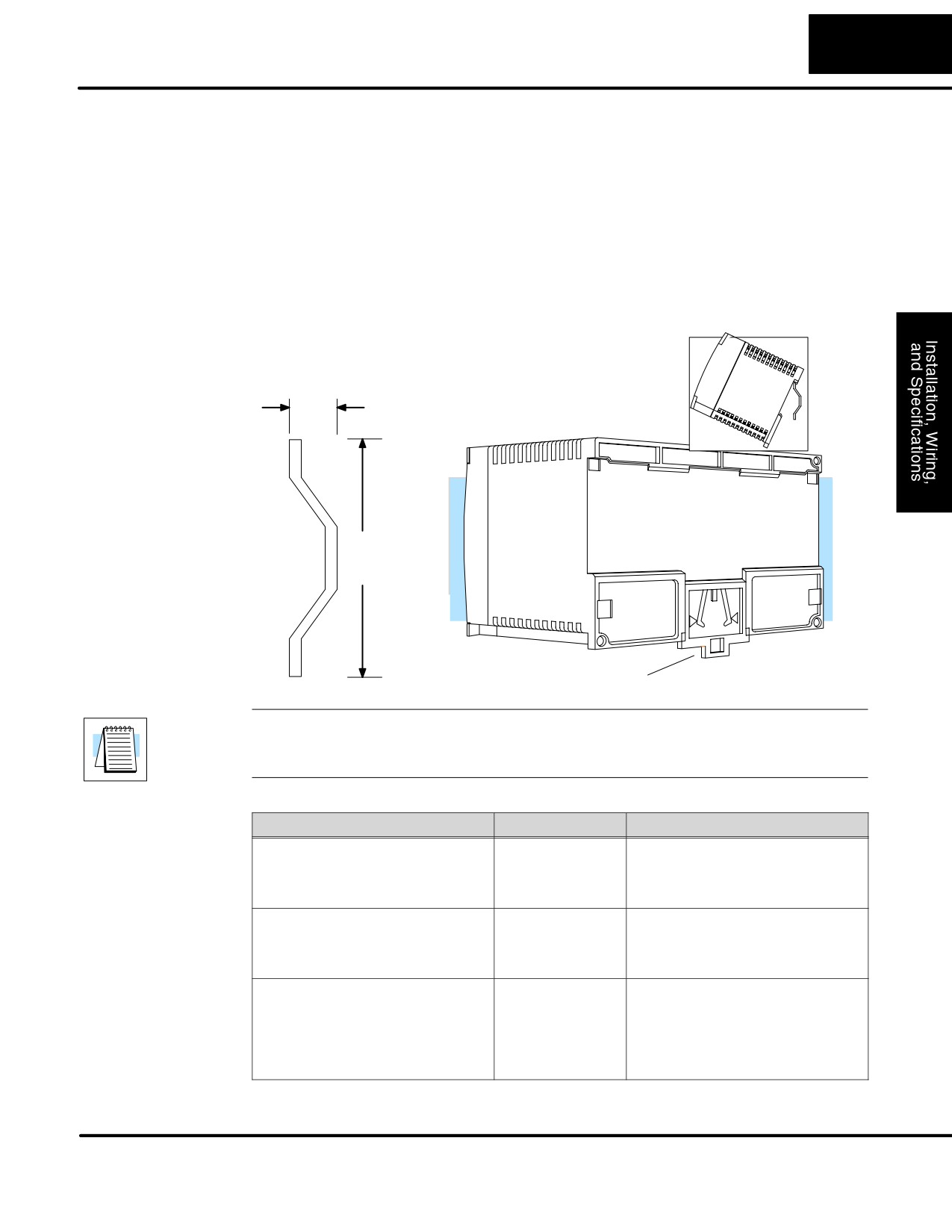
DL105 Micro PLCs can also be secured to a cabinet by using mounting rails. We
Rails
recommend rails that conform to DIN EN standard 50 022. They are approximately
35mm high, with a depth of 7.5mm. If you mount the Micro PLC on a rail, do consider
using end brackets on each side of the PLC. The end bracket helps keep the PLC
from sliding horizontally along the rail, reducing the possibility of accidentally pulling
the wiring loose.
On the bottom of the PLC is a small retaining clip. To secure the PLC to a DIN rail,
place it onto the rail and gently push up on the clip to lock it onto the rail.
To remove the PLC, pull down on the retaining clip, lift up on the PLC slightly, then
pulling it away from the rail.
DIN Rail Dimensions
DIN Rail slot.
Use 35mm x 7mm rail conforming to
DIN EN 50022.
7mm
35 mm
Retaining Clip
NOTE: We provide the following list as a guideline. Local and/or national codes may
require the use of a particular type of material. Consult the manufacturer or their
authorized representative prior to designing your system.
Vendor
Type
Materials and Lengths
Phoenix Contacts Products
NS 35/7,5
Steel, 6.5ft. (2m)
P.O. Box 4100
(part number 08 01 73 3)
Harrisburg, PA 17111-0100
717-944-1300
Weidmuller, Inc.
TS 35x7.5
Steel, aluminum, copper, PVC
821 Southlake Blvd.
Several lengths are available
Richmond, VA 23236
(consult manufacturer for
804-794-2877
appropriate part number)
Wieland
TS 35x27x7.5
Steel, 6.5ft. (2m)
available from
(part number 94F2750)
Newark Electronics
4108 North Ravenswood Ave.
Chicago, Il 60640
312-784-5100
DL105 PLC User Manual, 2nd Edition, Rev. A
2-10
Installation, Wiring, and Specifications
Wiring Guidelines
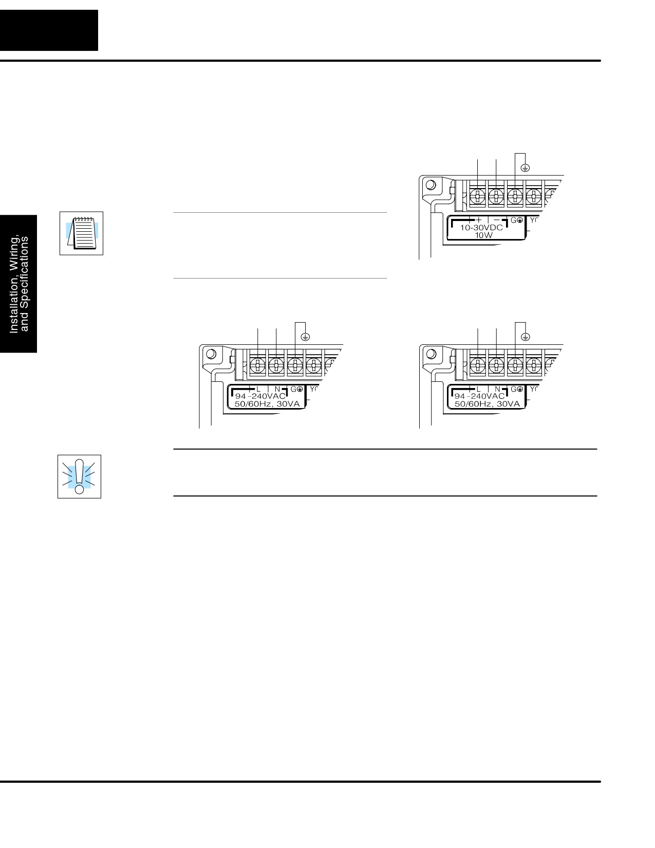
Power Input Wiring The diagram shows various possible
12/24 VDC Power Input
external power connections for DL105
10 - 30 VDC
Micro PLCs. The terminals can accept up
+
-
G
to 14 AWG wire. You may be able to use
larger wiring depending on the wire type,
but 14 AWG is the recommended size.
NOTE: You can connect either 115 VAC,
220 VAC, or 125 VDC to AC-powered
versions of the DL105. Special wiring or
jumpers are not required as with some of
the other DirectLOGIC products.
110/220 VAC Power Input
125 VDC Power Input
94 - 240 VAC
100 - 240 VDC
L
N
G
+
-
G
WARNING: Once the power wiring is connected, secure the terminal block cover in
the closed position. When the cover is open there is a risk of electrical shock if you
accidentally touch the connection terminals or power wiring.
Fuse Protection
There are no internal fuses for the input power circuits, so external circuit protection
for Input Power
is needed to ensure the safety of service personnel and the safe operation of the
equipment itself. To meet UL/CSA specifications, the input power must be fused.
Depending on the type of input power being used, follow these fuse protection
recommendations:
208/240 VAC Operation
When operating the unit from 208/240 VAC, whether the voltage source is a
step-down transformer or from two phases, fuse both the line (L) and neutral (N)
leads. The recommended fuse size is 0.375A (for example, a Littlefuse 312.375 or
equivalent).
110/125 VAC Operation
When operating the unit from 110/125 VAC, it is only necessary to fuse the line (L)
lead; it is not necessary to fuse the neutral (N) lead. The recommended fuse size is
0.5A (for example, a Littlefuse 312.500 or equivalent).
DL105 PLC User Manual, 2nd Edition, Rev. A
2-11
Installation, Wiring, and Specifications
125 VDC Operation
Proper fusing techniques are required when operating from 125 VDC. Depending on
your ground reference, the hot lead must be fused. A DC failure can maintain an arc
for much longer time and distance. Typically, the main bus is fused at a higher level
than the branch device, which in this case would be the DL105 unit. This double
fusing technique is required when operating from direct current. The recommended
fuse size for the branch circuit to the DL105 is 0.5A (for example, a Littlefuse 312.500
or equivalent).
12/24 VDC Operation
When operating at these lower dc voltages, wire gauge size is just as important as
proper fusing techniques. Using large conductors minimizes the voltage drop in the
conductor. Each DL105 input power terminal can accommodate one 14 AWG or two
16 AWG wires. Each terminal block junction and/or connection creates a voltage
drop, so try to keep the number of connections to a minimum. In general, when using
12/24 VDC input power, observe the same double fusing techniques that are used
with 125 VDC input power. The recommended fuse size for the branch circuit to the
DL105 is 1A (for example, a Littlefuse 312.001 or equivalent).
External
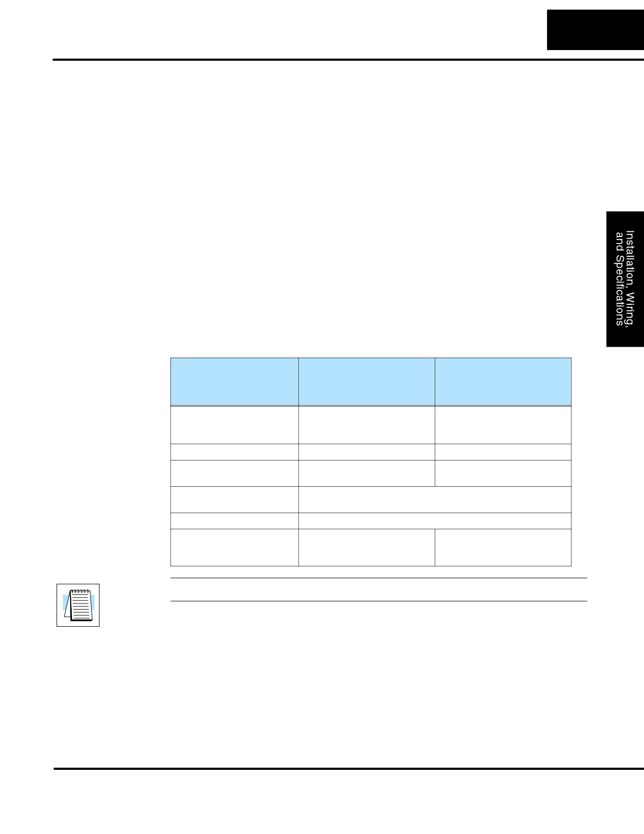
The power source must be capable of suppling voltage and current complying with
Power Source
individual Micro PLC specifications, according to the following specifications:
Part Numbers
F1-130AR, F1-130DR /
F1-130DR-D,
F1-130DR-CE, F1-130AD,
F1-130DD-D
F1-130DD / F1-130DD-CE,
F1-130AA, F1-130DA
Input Voltage Range
85-132 VAC (110 nominal)
10 - 30 VDC (12 to 24VDC)
170-264 VAC (220 nominal),
with less than 10% ripple
100 - 264 VDC (125 nominal)
Maximum Inrush Current
12 A, <1/2 mS
12 A, <1/2 mS
Maximum Power
30 VA (for AC power)
10W (0.3A @ 30VDC)
30 W (for DC power)
Voltage Withstand (dielectric)
1 minute @ 1500 VAC between primary, secondary, field
ground
Insulation Resistance
> 10 MW at 500 VDC
Auxiliary 24 VDC Output
21.6-26.4 VDC
None
Ripple less than 200 mV p-p
500 mA max, isolated.
NOTE:The rating between all internal circuits is BASIC INSULATION ONLY.
DL105 PLC User Manual, 2nd Edition, Rev. A
2-12
Installation, Wiring, and Specifications
Planning the
The following guidelines provide general information on how to wire the I/O
Wiring Routes
connections to DL105 Micro PLCs. For specific information on wiring a particular
PLC refer to the corresponding specification sheet further in this chapter.
1. Each terminal connection of the DL105 PLC can accept one 14 AWG wire
or two 16 AWG size wires. Do not exceed this recommended capacity.
2. Always use a continuous length of wire. Do not splice wires to attain a
needed length.
3. Use the shortest possible wire length.
4. Use wire trays for routing where possible.
5. Avoid running wires near high energy wiring.
6. Avoid running input wiring close to output wiring where possible.
7. To minimize voltage drops when wires must run a long distance , consider
using multiple wires for the return line.
8. Avoid running DC wiring in close proximity to AC wiring where possible.
9. Avoid creating sharp bends in the wires.
Fuse Protection
Input and Output circuits on DL105 Micro PLCs do not have internal fuses. However,
for Input and
the +24V Auxiliary Supply is current-limited. In order to protect your Micro PLC, we
Output Circuits
suggest you add external fuses to your I/O wiring. A fast-blow fuse, with a lower
current rating than the I/O bank’s common current rating can be wired to each
common. Or, a fuse with a rating of slightly less than the maximum current per output
point can be added to each output. Refer to the Micro PLC specification sheets
further in this chapter to find the maximum current per output point or per output
common. Adding the external fuse does not guarantee the prevention of Micro PLC
damage, but it will provide added protection.
External Fuses
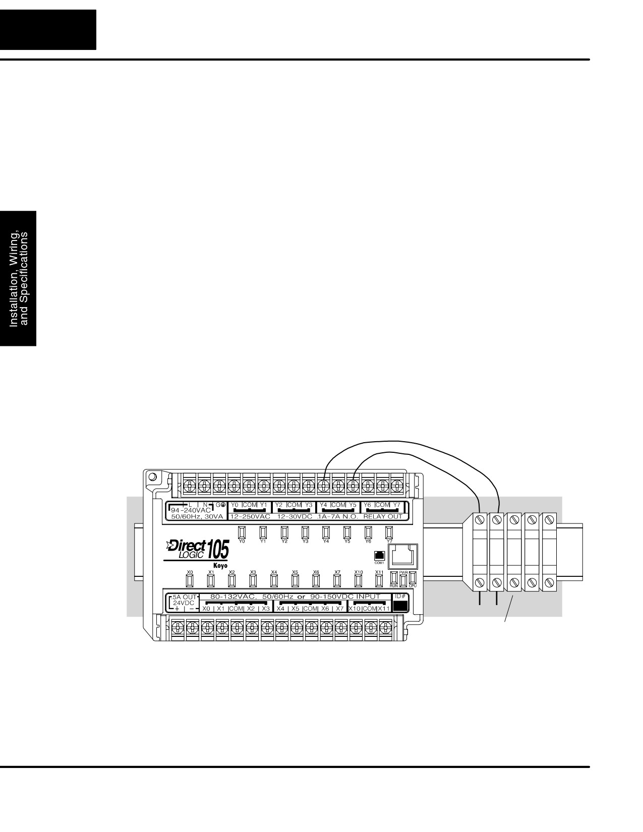
(shown with DIN Rail, Fuse Blocks)
I/O Point
All DL105 Micro PLCs have a fixed I/O configuration. It follows the same octal
Numbering
numbering system used on other DirectLogic family PLCs, starting at X0 and Y0. The
letter X is always used to indicate inputs and the letter Y is always used for outputs.
The I/O numbering always starts at zero and does not include the digits 8 or 9. The
addresses are typically assigned in groups of 8 or 16, depending on the number of
points in an I/O group. For the DL105 the ten inputs use reference numbers X0 - X7
and X10 - X11. The eight output points use references Y0 - Y7.
DL105 PLC User Manual, 2nd Edition, Rev. A
2-13
Installation, Wiring, and Specifications
System Wiring Strategies
The DL105 Micro PLC is very flexible and will work in many different wiring
configurations. By studying this section before actual installation, you can probably
find the best wiring strategy for your application . This will help to lower system cost,
wiring errors, and avoid safety problems.
PLC Isolation
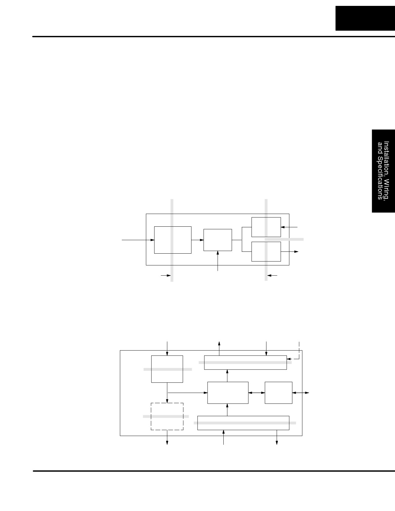
PLC circuitry is divided into three main regions separated by isolation boundaries,
Boundaries
shown in the drawing below. Electrical isolation provides safety, so that a fault in one
area does not damage another. A transformer in the power supply provides
magnetic isolation between the primary and secondary sides. Opto-couplers
provide optical isolation in Input and Output circuits. This isolates logic circuitry from
the field side, where factory machinery connects. Note that the discrete inputs are
isolated from the discrete outputs, because each is isolated from the logic side.
Isolation boundaries protect the operator interface (and the operator) from power
input faults or field wiring faults. When wiring a PLC, it is extremely important to avoid
making external connections that connect logic side circuits to any other.
Primary Side
Secondary, or
Field Side
Logic side
PLC
Input
Discrete Inputs
Main
Circuit
Power Input
Power
CPU
Supply
Output
Discrete Outputs
Circuit
Isolation
Programming Device or
Isolation
Boundary
Operator Interface
Boundary
The next figure shows the internal layout of DL105 PLCs, as viewed from the front
panel. In addition to the basic circuits covered above, it includes an auxiliary
+24VDC power supply with its own isolation boundary. Since the supply output is
isolated from the other three circuits, it can power input and/or output circuits!
Power Input
Power Input
8 Discrete Outputs
Commons
(DC Out versions only)
DL105
PLC
Main
Output Circuit
Power
Supply
Comm.
To Programming
CPU
Port
Device, or
Operator
Auxiliary
Interface
+24VDC
Supply
Input Circuit
+24VDC Out
10 Discrete Inputs
Commons
(AC-powered versions only)
DL105 PLC User Manual, 2nd Edition, Rev. A
//////////////////////////////////////////