DL105 Micro PLC. User Manual (2003) - page 7
6-3
Drum Instruction Programming
Drum Chart
For editing purposes, the electronic drum is presented in chart form in
Representation
DirectSOFT32 and in this manual. Imagine slicing the surface of a hollow drum
cylinder between two rows of pegs, then pressing it flat. Now you can view the drum
as a chart as shown below. Each row represents a step, numbered 1 through 16.
Each column represents an output, numbered 0 through 15 (to match word bit
numbering). The solid circles in the chart represent pegs (On state) in the
mechanical drum, and the open circles are empty peg sites (Off state).
OUTPUTS
STEP
15 14 13 12 11
10 9
8
7
6
5
4
3
2
1
0
1
f F f F f f F f f f F f f F f f
2
f F f F F f F f f f f F f f F f
3
f F F F F f F F f f f f f f f f
4
F F f F F f F f F f f f f f f F
5
f f f F f f F f F f F f F f f F
6
f f f F f f F f F f F f F F f F
7
F f f F f f F F F F f F F F f F
8
F f F f f F f F F f f f F f f F
9
f f f f f f f F F f f f F f f f
10
f f f f f f f F F F f f f f f f
11
F f f f F f f f f F f f f f F f
12
f F f f F F f f F f F F f F F f
13
f f F f f f f f f f f F F f F f
14
f f f f f f f F f f f F F f F F
15
F f f f f F f F f F f F f f F F
16
f f F f f f f F f F f F F f f F
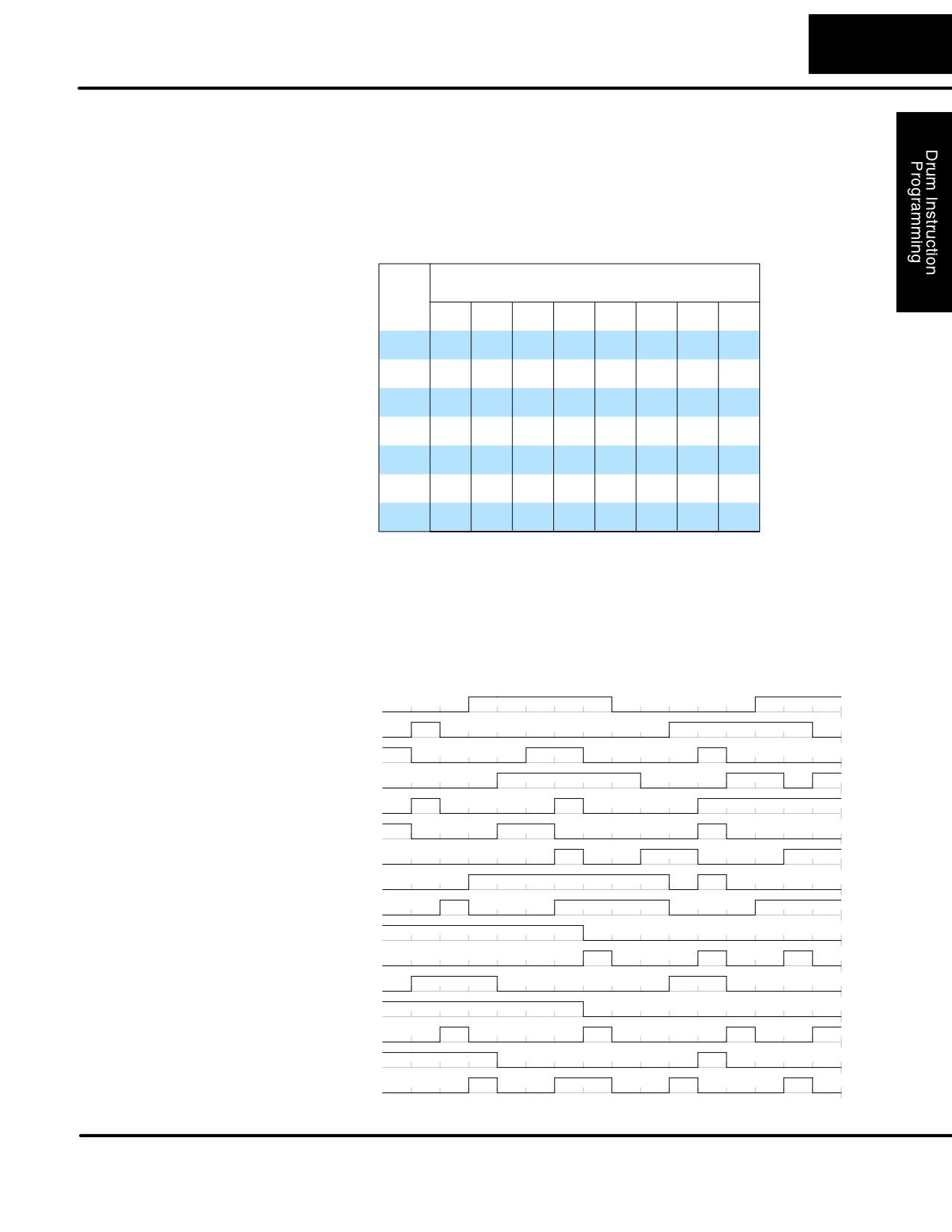
The mechanical drum sequencer derives its name from sequences of control
Output Sequences
changes on its electrical outputs. The following figure shows the sequence of On/Off
controls generated by the drum pattern above. Compare the two, and you will find
that they are equivalent! If you can see their equivalence, you are well on your way to
understanding drum instruction operation.
Step
1
2
3
4
5
6
7
8
9
10
11
12
13
14
15
16
Output
1
0
0
1
1
0
1
2
0
1
3
0
1
4
0
1
5
0
1
6
0
1
7
0
1
8
0
1
9
0
1
10
0
1
11
0
1
12
0
1
13
0
1
14
0
1
15
0
DL105 PLC User Manual, 2nd Edition, Rev. A
6-4
Drum Instruction Programming
Step Transitions
Drum Instruction
EDRUM operation in the F1-130 includes the following features:
Parameters
S Up to 16 steps
S Time-based step transitions
S Event-based step transitions
S Up to 16 discrete outputs per drum (X, Y, or C type)
The EDRUM has 16 steps, and each step has 16 outputs. Refer to the figure below.
Each output can be either an X, Y, or C coil, offering a lot of programming flexibility.
We assign Step 1 an arbitrary unique output pattern (f= Off, F= On) as shown.
When programming the EDRUM instruction, you also determine both the output
assignment and the On/Off state (pattern) at that time. All steps use the same output
assignment, but each step may have its own unique output pattern.
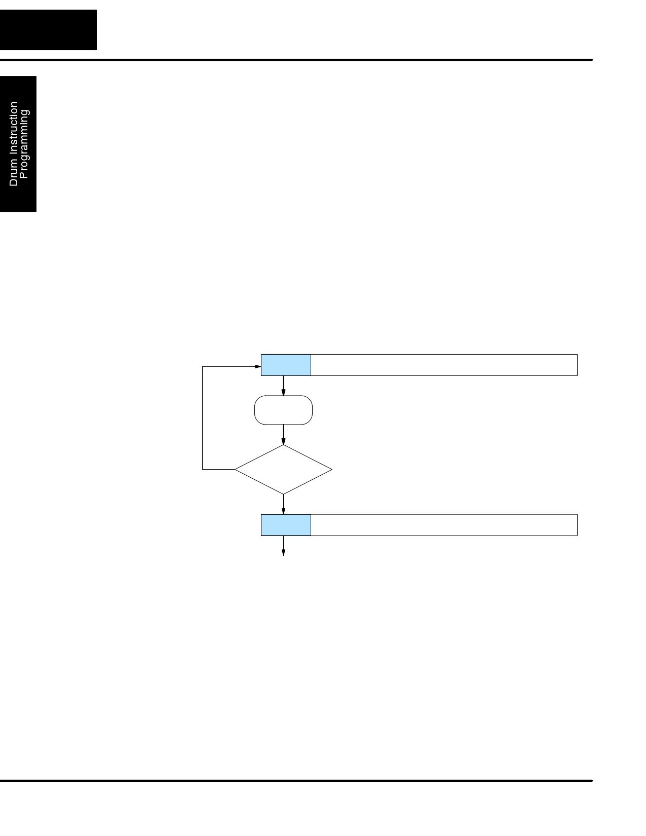
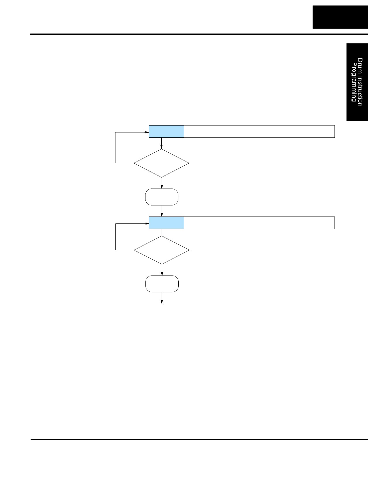
Timer-Only
Drums move from one step to another based on time and/or an external event
Transitions
(input). Each step has its own transition condition which you assign during the drum
instruction entry. The figure below shows how timer-only transitions work.
Step 1
Outputs: F f f f F f F f f f f F F f f f
Increment
count timer
No
Has counts per
step expired?
Yes
Step 2
Outputs:
f f f
F f f f f F F f F f f F F
Use next transition criteria
The drum stays in Step 1 for a specific duration (user-programmable). The timebase
of the timer is programmable, from 0.01 seconds to 99.99 seconds. This establishes
the resolution, or the duration of each “tick of the clock”. Each step uses the same
timebase, but has its own unique counts per step, which you program. When the
counts for Step 1 have expired, then the drum moves to Step 2. The outputs change
immediately to match the new pattern for Step 2.
The drum spends a specific amount of time in each step, given by the formula:
Time in step = 0.01 seconds X Timebase x Counts per step
DL105 PLC User Manual, 2nd Edition, Rev. A
6-5
Drum Instruction Programming
For example, if you program a 5 second time base and 12 counts for Step 1, then the
drum will spend 60 seconds in Step 1. The maximum time for any step is given by the
formula:
Max Time per step = 0.01 seconds X 9999 X 9999
= 999,800 seconds = 277.7 hours = 11.6 days
NOTE: When first choosing the timebase resolution, a good rule of thumb is to make
it about 1/10 the duration of the shortest step in your drum. Then you will be able to
optimize the duration of that step in 10% increments. Other steps with longer
durations allow optimizing by even smaller increments (percentage-wise). Also,
note that the drum instruction executes once per CPU scan. Therefore, it is pointless
to specify a drum timebase that is much faster than the CPU scan time.
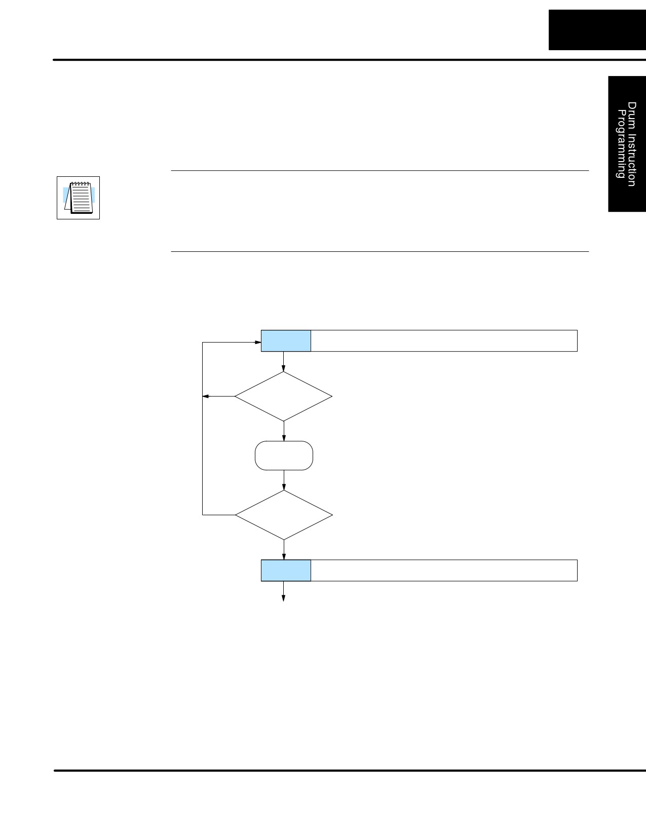
Timer and Event
Step transitions may also occur based on time and/or external events. The figure
Transitions
below shows how step transitions work in these cases.
Step 1
Outputs: F f f f F f F f f f f F F f f f
No
Is Step event
true?
Yes
Increment
count timer
Has step
No
counts expired?
Yes
Step 2
Outputs:
f f f
F f f f f F F f F f f F F
Use next transition criteria
When the drum enters Step 1, it sets the output pattern as shown. Then it begins
polling the external input programmed for that step. You can define event inputs as
X, Y, or C discrete point types. Suppose we select X0 for the Step 1 event input. If X0
is off, then the drum remains in Step 1. When X0 is On, the event criteria is met and
the timer increments. The timer increments as long as the event (X0) remains true.
When the counts for Step 1 have expired, then the drum moves to Step 2. The
outputs change immediately to match the new pattern for Step 2.
DL105 PLC User Manual, 2nd Edition, Rev. A
6-6
Drum Instruction Programming
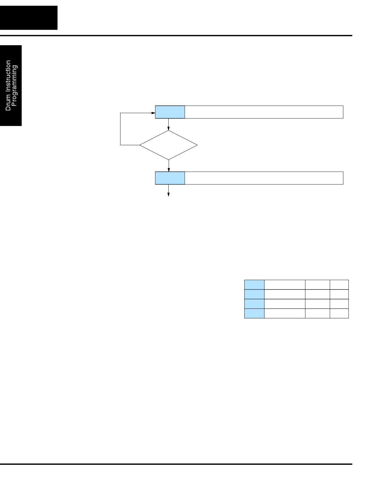
Event-Only
Step transitions do not require both the event and the timer criteria programmed for
Transitions
each step. You have the option of programming just one of the two, and even mixing
transition types among all the steps of the drum. For example, you might want Step 1
to transition on an event, Step 2 to transition on time only, and Step 3 to transition on
both time and an event. Furthermore, you may elect to use only part of the 16 steps,
and only part of the 16 outputs.
Step 1
Outputs: F f f f F f F f f f f F F f f f
No
Is Step event
true?
Yes
Step 2
Outputs:
f f f
F f f f f F F f F f f F F
Use next transition criteria
Counter
Each drum instruction uses the resources of four counters in the CPU. When
Assignments
programming the drum instruction, you select the first counter number. The drum
also uses the next three counters automatically. The counter bit associated with the
first counter turns on when the drum has completed its cycle, going off when the
drum is reset. These counter values and the counter bit precisely indicate the
progress of the drum instruction, and can be monitored by your ladder program.
Suppose we program a timer drum to have
Counter Assignments
8 steps, and we select CT10 for the
CT10
Counts in step
V1010
1528
counter number
(remember, counter
CT11
Timer Value
V1011
0200
numbering is in octal). Counter usage is
shown to the right. The right column holds
CT12
Preset Step
V1012
0001
typical values, interpreted below.
CT13
Current Step
V1013
0004
CT10 shows that we are at the 1528th count in the current step, which is step 4
(shown in CT13). If we have programmed step 4 to have 3000 counts, then the step
is just over half completed. CT11 is the count timer, shown in units of 0.01 seconds.
So, each least-significant-digit change represents 0.01 seconds. The value of 200
means that we have been in the current count (1528) for 2 seconds (0.01 x 100).
Finally, CT12 holds the preset step value which was programmed into the drum
instruction. When the drum’s Reset input is active, it presets to step 1 in this case.
The value of CT12 changes only if the ladder program writes to it, or the drum
instruction is edited and the program is restarted. Counter bit CT10 turns on when
the drum cycle is complete, and turns off when the drum is reset.
DL105 PLC User Manual, 2nd Edition, Rev. A
6-7
Drum Instruction Programming
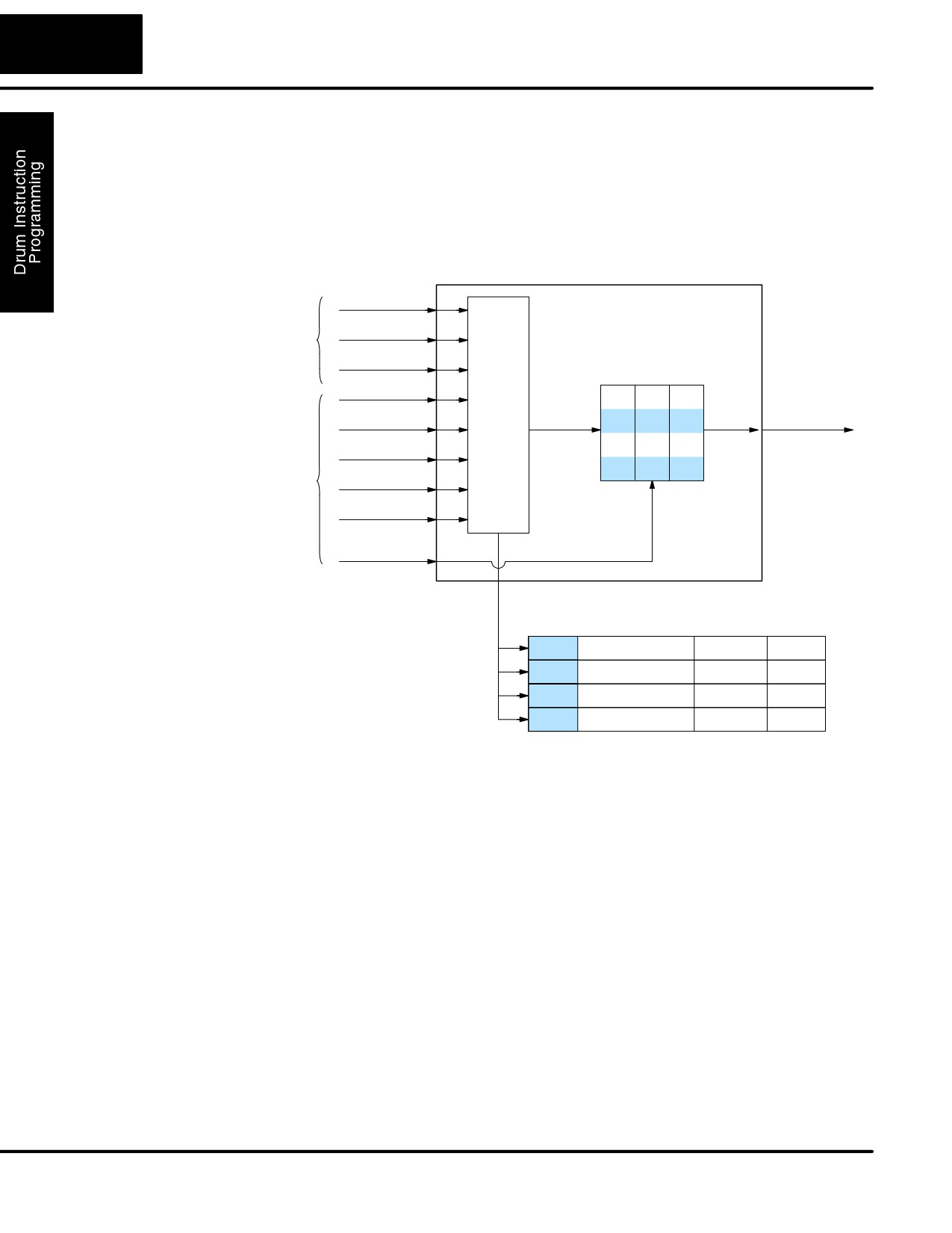
Last Step
The last step in a drum sequence may be any step number, since partial drums are
Completion
valid. Refer to the following figure. When the transition conditions of the last step are
met, the drum sets the counter bit corresponding to the counter named in the drum
instruction box (such as CT0). Then it moves to a final “drum complete” state. The
drum outputs remain in the pattern defined for the last step. Having finished a drum
cycle, the Start and Jog inputs have no effect at this point.
The drum leaves the “drum complete” state when the Reset input becomes active (or
on a program-to-run mode transition). It resets the drum complete bit (such as CT0),
and then goes directly to the appropriate step number defined as the preset step.
Last step
Outputs: F F F f f f F f f F f F F F f F
No
Are transition
(Timer and/or
conditions met?
Event criteria)
Yes
Set
Set Drum Complete bit
CT0 = 1
Complete
Outputs: F F F f f f F f f F f F F F f F
No
Reset Input
Active?
Yes
Reset
Reset Drum Complete bit
CT0 = 0
Go to Preset Step
DL105 PLC User Manual, 2nd Edition, Rev. A
6-8
Drum Instruction Programming
Overview of Drum Operation
Drum Instruction
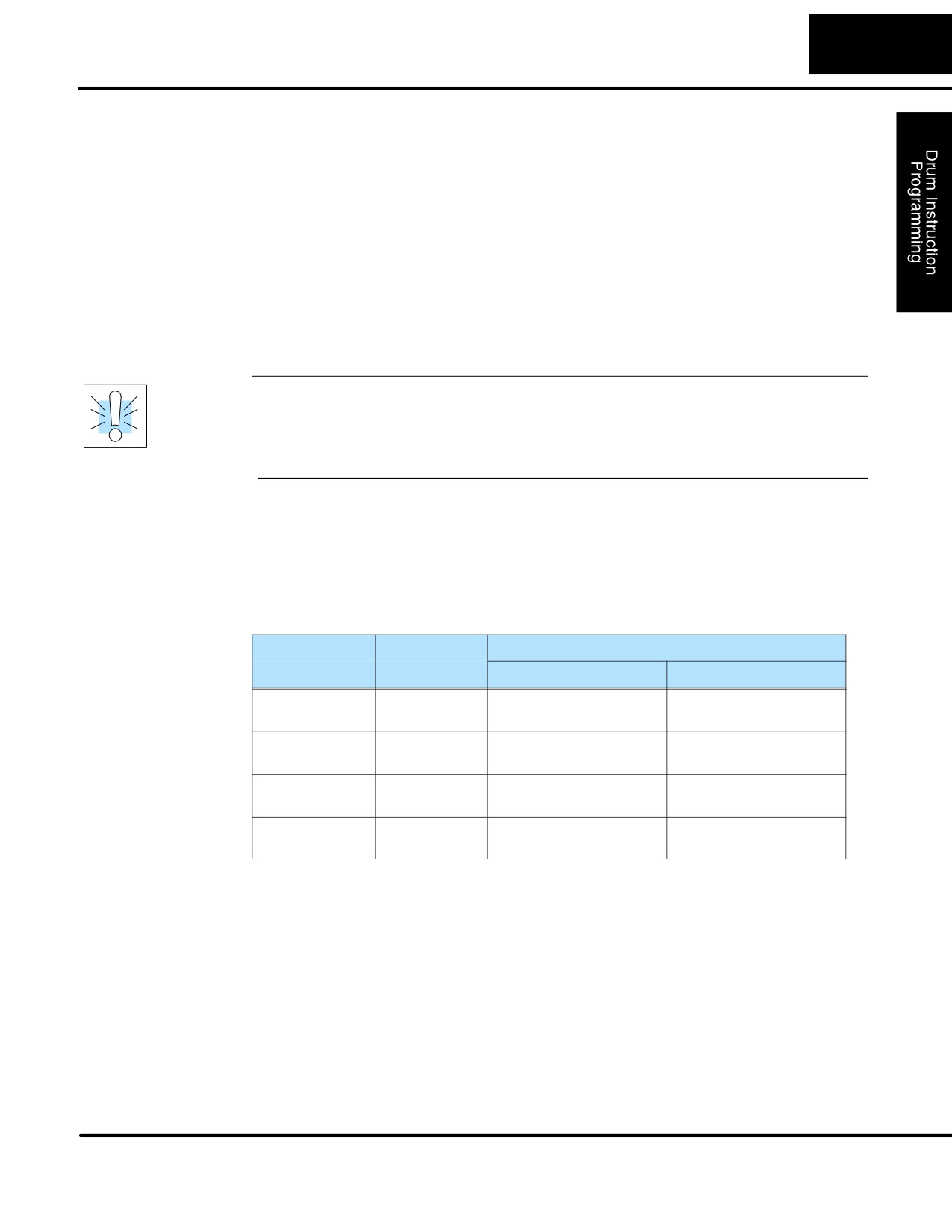
The drum instruction utilizes various inputs and outputs in addition to the drum
Block Diagram
pattern itself. Refer to the figure below.
Inputs
DRUM INSTRUCTION
Outputs
Block Diagram
Start
Realtime
Jog
Inputs
(from ladder)
Reset
Drum
Preset Step
f f
F f
f f
f f
f f
f f
Step
Final Drum
f f
f f
F f
Counts/Step
Step
Pointer
Outputs
F F
f F
F f
Control
f F
F f
F f
Timebase
f F
F f
F F
f F
f f
F F
Programming
f F
F f
f F
Selections
Events
Counter #
Pattern
Counter Assignments
CT0
Counts in step
V1000
xxxx
CT1
Timer Value
V1001
xxxx
CT2
Preset Step
V1002
xxxx
CT3
Current Step
V1003
xxxx
The drum instruction accepts several inputs for step control, the main control of the
drum. The inputs and their functions are:
S Start - The Start input is effective only when Reset is off. When Start is
on, the drum timer runs if it is in a timed transition, and the drum looks
for the input event during event transitions. When Start is off, the drum
freezes in its current state (Reset must remain off), and the drum
outputs maintain their current on/off pattern.
S Jog - The jog input is only effective when Reset is off (Start may be
either on or off). The jog input increments the drum to the next step on
each off-to-on transition.
S Reset - The Reset input has priority over the Start input. When Reset is
on, the drum moves to its preset step. When Reset is off, then the Start
input operates normally.
S Preset Step - A step number from 1 to 16 that you define (typically is
step 1). The drum moves to this step whenever Reset is on, and
whenever the CPU first enters run mode.
DL105 PLC User Manual, 2nd Edition, Rev. A
6-9
Drum Instruction Programming
S Counts/Step - The number of timer counts the drum spends in each
step. Each step has its own counts parameter. However, programming
the counts/step is optional.
S Timer Value - the current value of the counts/step timer.
S Counter # - The counter number specifies the first of four consecutive
counters which the drum uses for step control. You can monitor these to
determine the drum’s progress through its control cycle. The DL105 has
64 counters (CT0 - CT77 in octal).
S Events - Either an X, Y, C, S, T, or CT type discrete point serves as
step transition inputs. Each step has its own event. However,
programming the event is optional.
WARNING: The outputs of a drum are enabled any time the CPU is in Run Mode.
The Start Input does not have to be on, and the Reset input does not disable the
outputs. Upon entering Run Mode, drum outputs automatically turn on or off
according to the pattern of the current step of the drum. This initial step number
depends on the counter memory configuration: non-retentive versus retentive.
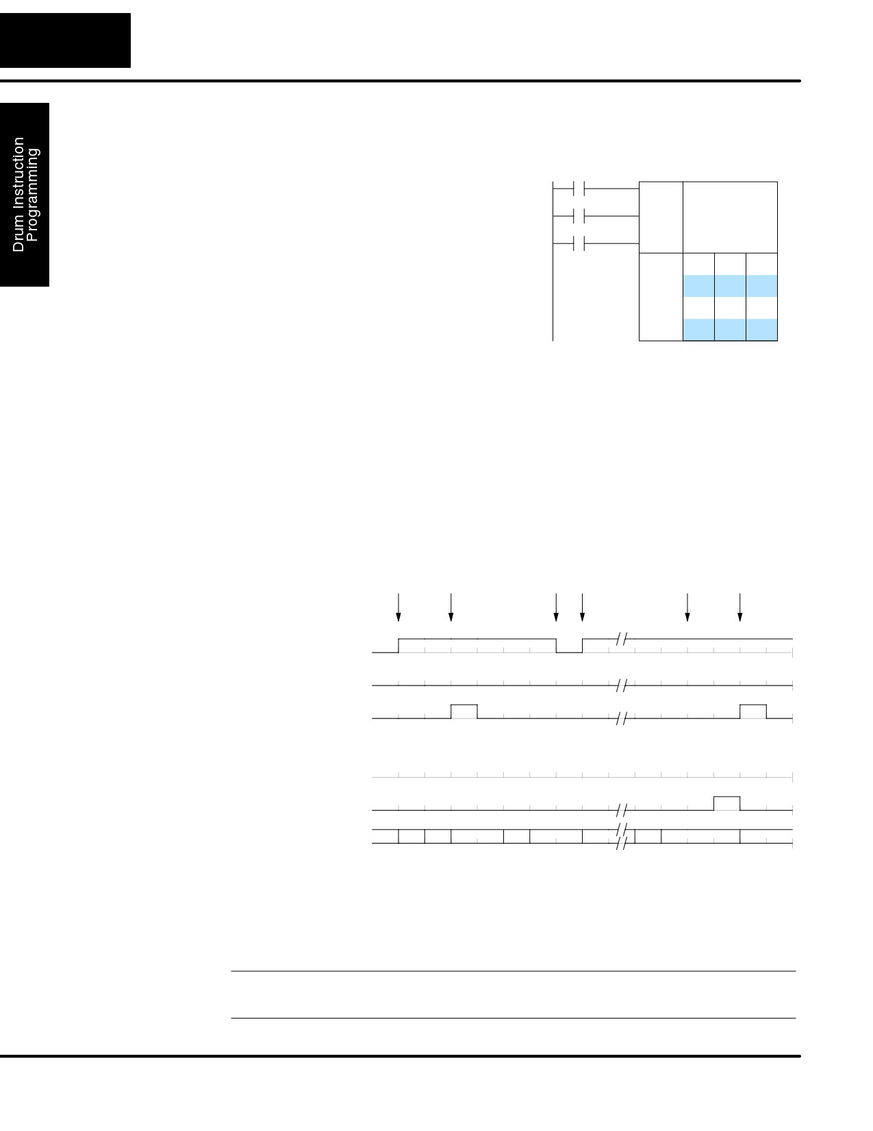
Powerup State of
The choice of the starting step on powerup and program-to-run mode transitions are
Drum Registers
important to consider for your application. Please refer to the following chart. If the
counter memory is configured as non-retentive, the drum is initialized the same way
on every powerup or program-to-run mode transition. However, if the counter
memory is configured to be retentive, the drum will stay in its previous state.
Counter Num-
Function
Initialization on Powerup
ber
Non-Retentive Case
Retentive Case
CT(n)
Current Step
Initialize = 0
Use Previous (no
Count
change)
CT(n + 1)
Counter Timer
Initialize = 0
Use Previous (no
Value
change)
CT(n + 2)
Preset Step
Initialize = Preset Step #
Use Previous (no
change)
CT(n + 3)
Current Step #
Initialize = Preset Step #
Use Previous (no
change)
Applications with relatively fast drum cycle times typically will need to be reset on
powerup, using the non-retentive option. Applications with relatively long drum cycle
times may need to resume at the previous point where operations stopped, using the
retentive case. The default option is the retentive case. This means that if you
initialize scratchpad V-memory, the memory will be retentive.
DL105 PLC User Manual, 2nd Edition, Rev. A
6-10
Drum Instruction Programming
Drum Control Techniques
Drum
Now we are ready to put together the
X0
Start
Control Inputs
concepts on the previous pages and
X1
demonstrate general control of the drum
Jog
Setup
Outputs
Info.
instruction box. The drawing to the right
X2
Reset
shows a simplified generic drum
f f
F f
f f
instruction. Inputs from ladder logic
Steps
f f
f f
f f
f f
f f
F f
control the Start, Jog, and Reset Inputs.
F F
f F
F f
The first counter bit of the drum (CT0, for
f F
F f
F f
f F
F f
F F
example) indicates the drum cycle is
f F
f f
F F
done.
f F
F f
f F
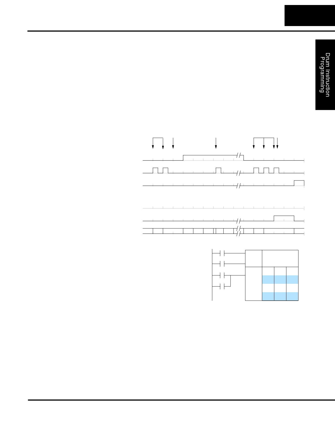
The timing diagram below shows an arbitrary timer drum input sequence and how
the drum responds. As the CPU enters Run mode it initializes the step number to the
preset step number (typically it is Step 1). When the Start input turns on the drum
begins running, waiting for an event and/or running the timer (depends on the setup).
After the drum enters Step 2, Reset turns On while Start is still On. Since Reset has
priority over Start, the drum goes to the preset step (Step 1). Note that the drum is
held in the preset step during Reset, and that step does not run (respond to events or
run the timer) until Reset turns off.
After the drum has entered step 3, the Start input goes off momentarily, halting the
drum’s timer until Start turns on again.
Start
Reset
Hold Resume
Drum
Reset
drum drum
drum drum
Complete drum
Inputs
1
Start
0
1
Jog
0
1
Reset
0
Drum Status
1
1
2
1
1
2
3
3
4
15
16
16
16
1
1
Step #
1
Drum
Complete (CT0)
0
1
Outputs (x 16)
0
When the drum completes the last step (Step 16 in this example), the Drum
Complete bit (CT0) turns on, and the step number remains at 16. When the Reset
input turns on, it turns off the Drum Complete bit (CT0), and forces the drum to enter
the preset step.
NOTE: The timing diagram shows all steps using equal time durations. Step times
can vary greatly, depending on the counts/step programmed.
DL105 PLC User Manual, 2nd Edition, Rev. A
6-11
Drum Instruction Programming
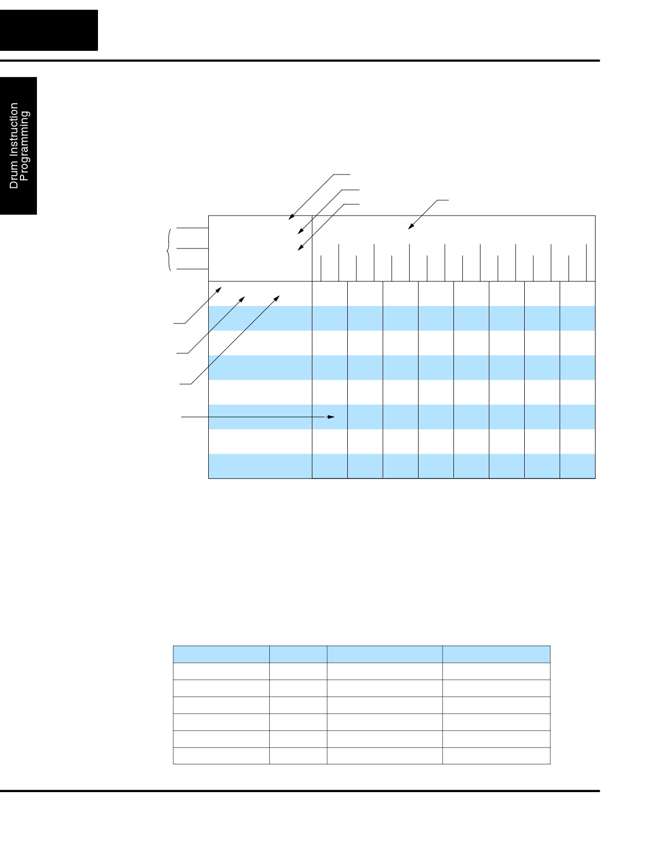
In the figure below, we focus on how the Jog input works on event drums. To the left
of the diagram, note that the off-to-on transitions of the Jog input increments the
step. Start may be either on or off (however, Reset must be off). Two jogs takes the
drum to step three. Next, the Start input turns on, and the drum begins running
normally. During step 6 another Jog input signal occurs. This increments the drum to
step 7, setting the timer to 0. The drum begins running immediately in step 7,
because Start is already on. The drum advances to step 8 normally.
As the drum enters step 14, the Start input turns off. Two more Jog signals moves the
drum to step 16. However, note that a third Jog signal is required to move the drum
through step 16 to “drum complete”. Finally, a Reset input signal arrives which forces
the drum into the preset step and turns off the drum complete bit.
Jog
Reset
Jog
Jog
Drum
drum drum
drum
drum
Complete
Inputs
1
Start
0
1
Jog
0
1
Reset
0
Drum Status
1
2
3
3
3
4
5
6,7
8
14
15
16
16
16
1
Step #
1
Drum
Complete (CT0)
0
1
Outputs (x 16)
0
Self-Resetting
Applications often require drums that
X0
Start
Drum
automatically start over once they
Setup
X1
Outputs
complete a cycle. This is easily
Start
Info.
accomplished, using the drum complete
f f
F f
f
f
X2
Steps
Reset
f f
f f
f
f
bit. In the figure to the right, the drum
f f
f f
F
f
instruction setup is for CT0, so we logically
CT0
F F
f F
F
f
f F
F f
F
f
OR the drum complete bit (CT0) with the
f F
F f
F
F
Reset input. When the last step is done,
f F
f f
F
F
f F
F f
f
F
the drum turns on CT0 which resets itself
to the preset step, also resetting CT0.
Contact X2 still works as a manual reset.
Initializing Drum
The outputs of a drum are enabled any
time the CPU is in run mode. On
Outputs
program-to-run mode transitions, the drum goes to the preset step, and the outputs
energize according to the pattern of that step. If your application requires all outputs
to be off at powerup, make the preset step in the drum a “reset step”, with all outputs
off.
Using Complex
Each event-based transition accepts only one contact reference for the event.
Event Step
However, this does not limit events to just one contact. Just use a control relay
Transitions
contact such as C0 for the step transition event. Elsewhere in ladder logic, you may
use C0 as an output coil, making it dependent on many other “events” (contacts).
DL105 PLC User Manual, 2nd Edition, Rev. A
6-12
Drum Instruction Programming
Drum Instruction
Event Drum
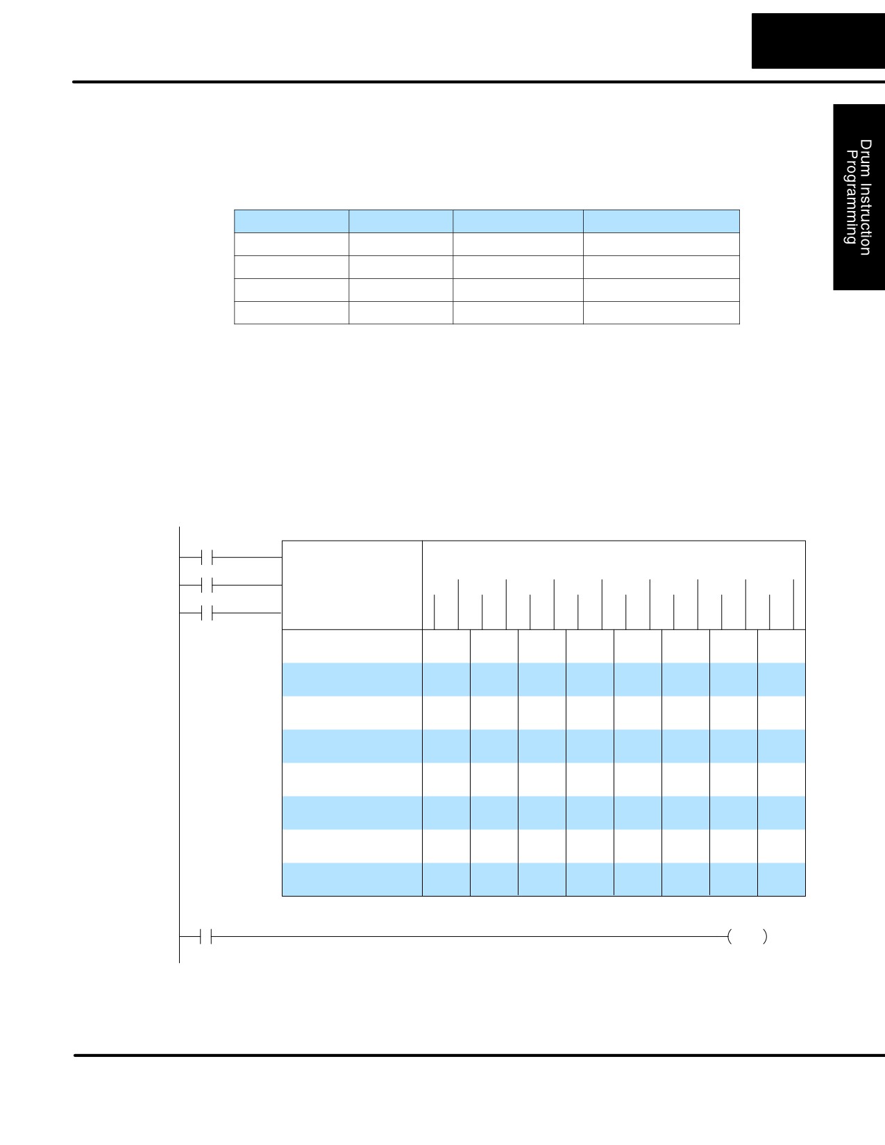
The Event Drum (EDRUM) features time-based and event-based step transitions. It
(EDRUM)
operates according to the general principles of drum operation covered in the
beginning of this chapter. Below is the instruction as displayed by DirectSOFT32.
Counter Number
EDRUM2
Step Preset
Timebase
Discrete Output Assignment
Start
EDRUM CT aa
15
0
Step Preset K bb
(Ffff)
(Ffff)
(Ffff)
(Ffff)
(Ffff)
(Ffff)
(Ffff)
(Ffff)
Control
Jog
(Ffff)
(Ffff)
(Ffff)
(Ffff)
(Ffff)
(Ffff)
(Ffff)
(Ffff)
Inputs
0.01 sec/Count
Reset
K cccc
Step # Counts Event
1
Kdddd
Eeeee
f f
f f
f f
f f
f f
f f
f f
f f
2
Kdddd
Eeeee
f f
f f
f f
f f
f f
f f
f f
f f
3
Kdddd
Eeeee
f f
f f
f f
f f
f f
f f
f f
f f
Step Number
4
Kdddd
Eeeee
f f
f f
f f
f f
f f
f f
f f
f f
5
Kdddd
Eeeee
f f
f f
f f
f f
f f
f f
f f
f f
6
Kdddd
Eeeee
f f
f f
f f
f f
f f
f f
f f
f f
Counts per Step
7
Kdddd
Eeeee
f f
f f
f f
f f
f f
f f
f f
f f
8
Kdddd
Eeeee
f f
f f
f f
f f
f f
f f
f f
f f
Event per step
9
Kdddd
Eeeee
f f
f f
f f
f f
f f
f f
f f
f f
10
Kdddd
Eeeee
f f
f f
f f
f f
f f
f f
f f
f f
Output Pattern
11
Kdddd
Eeeee
f f
f f
f f
f f
f f
f f
f f
f f
f= Off, F= On
12
Kdddd
Eeeee
f f
f f
f f
f f
f f
f f
f f
f f
13
Kdddd
Eeeee
f f
f f
f f
f f
f f
f f
f f
f f
14
Kdddd
Eeeee
f f
f f
f f
f f
f f
f f
f f
f f
15
Kdddd
Eeeee f f
f f
f f
f f
f f
f f
f f
f f
16
Kdddd
Eeeee
f f
f f
f f
f f
f f
f f
f f
f f
The Event Drum features 16 steps and 16 discrete outputs. Step transitions occur on
timed and/or event basis. The jog input also advances the step on each off-to-on
transition. Time is specified in counts per step, and events are specified as discrete
contacts. Unused steps must be programmed with “counts per step” = 0, and event =
“K0000”. The discrete output points may be individually assigned.
Whenever the Start input is energized, the drum’s timer is enabled. As long as the
event is true for the current step, the timer runs during that step. When the step count
equals the counts per step, the drum transitions to the next step. This process stops
when the last step is complete, or when the Reset input is energized. The drum
enters the preset step chosen upon a CPU program-to-run mode transition, and
whenever the Reset input is energized.
Drum Parameters
Field
Data Types
Ranges
Counter Number
aa
-
0 - 74
Preset Step
bb
K
1 - 16
Timer base
cccc
K
0.01 - 99.99 seconds
Counts per step
dddd
K
0 - 9999
Event
eeee
X, Y, C, S, T, CT
see page 4-28
Discrete Outputs
ffff
X, Y, C
see page 4-28
DL105 PLC User Manual, 2nd Edition, Rev. A
6-13
Drum Instruction Programming
Drum instructions use four counters in the CPU. The ladder program can read the
counter values for the drum’s status. The ladder program may write a new preset
step number to CT(n+2) at any time. However, the other counters are for monitoring
purposes only.
Counter Number
Ranges of (n)
Function
Counter Bit Function
CT(n)
0 - 74
Counts in step
CTn = Drum Complete
C( n+1)
1 - 75
Timer value
CT(n+1) = (not used)
CT( n+2)
2 -76
Preset Step
CT(n+2) = (not used)
CT( n+3)
3 -77
Current Step
CT(n+1) = (not used)
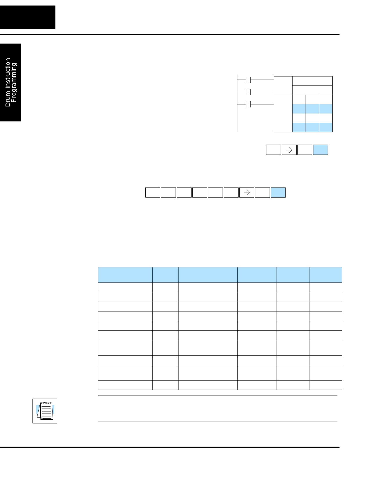
The following ladder program shows the EDRUM instruction in a typical ladder
program, as shown by DirectSOFT32. Steps 1 through 11 are used, and all sixteen
output points are used. The preset step is step 1. The timebase runs at (K100 x 0.01)
= 0.1 second per count. Therefore, the duration of step 1 is (5 x 0.1) = 0.5 seconds.
Note that step 1 is time-based only (event = “K0000”). And, the output pattern for
step 1 programs all outputs off, which is a typically desirable powerup condition. In
the last rung, the Drum Complete bit (CT4) turns on output Y0 upon completion of the
last step (step 10). A drum reset also resets CT4.
DirectSOFT32
X0
Start
15
0
EDRUM CT 4
X1
Step Preset K 1
(C34)
(Y6)
(C14)
(Y0)
(C4)
(Y5)
(Y1)
(C7)
Jog
(Y3)
(Y7)
(C30)
(Y2)
(C2)
(Y6)
(Y4)
(C10)
X2
0.01 sec/Count: K 100
Reset
Step # Counts Event
1
K0005
K0000
f f
f f
f f
f f
f f
f f
f f
f f
2
K0020
C3
F f
f F
F f
f f
f f
f F
f f
F f
3
K0150
X1
f f
F f
F f
f f
F f
f F
f F
f f
4
K0048
X2
f F
f f
f F
f f
f F
F F
f F
F f
5
K0180
C0
f F
f F
f f
f F
f F
F f
F f
f F
6
K0923
C1
F f
f F
f f
F F
f F
f f
f f
F F
7
K0120
X0
f F
f f
f F
f f
F f
f f
f F
F f
8
K0864
X5
F f
f F
f f
F f
f F
f F
F f
f F
9
K1200
X3
f f
f f
f f
F F
F f
f f
F f
F f
10
K0400
C12
f F
f F
F f
f f
f F
F f
f F
f f
11
K0000
C20
F f
f f
f F
f f
f F
f f
f F
F F
12
K0000
Eeeee
f f
f f
f f
f f
f f
f f
f f
f f
13
K0000
Eeeee
f f
f f
f f
f f
f f
f f
f f
f f
14
K0000
Eeeee
f f
f f
f f
f f
f f
f f
f f
f f
15
K0000
Eeeee
f f
f f
f f
f f
f f
f f
f f
f f
16
K0000
Eeeee
f f
f f
f f
f f
f f
f f
f f
f f
CT4
Y0
Drum Complete
OUT
DL105 PLC User Manual, 2nd Edition, Rev. A
6-14
Drum Instruction Programming
Handheld
The EDRUM instruction may be programmed using either DirectSOFT32 or a
Programer
handheld programmer. This section covers entry via the handheld programmer
Drum Mnemonics
(Refer to the DirectSOFT32 manual for drum instruction entry using that tool).
X0
First, enter Store instructions for the
Start
Setup
Outputs
ladder rungs controlling the drum’s ladder
X1
Jog
Info.
inputs. In the example to the right, the
Mask
f f
F f
f f
timer drum’s Start, Jog, and Reset inputs
X2
Steps
Reset
f f
f f
f f
are controlled by X0, X1 and X2
f f
f f
F f
F F
f F
F f
respectively. The required keystrokes are
f F
F f
F f
listed beside the mnemonic.
f F
F f
F F
f F
f f
F F
These keystrokes precede the EDRUM
f F
F f
f F
instruction mnemonic. Note that the
Handheld Programmer Keystrokes
ladder rungs for Start, Jog, and Reset
$
A
Store X0
ENT
inputs are not limited to being
STR
0
single-contact rungs.
(Repeat for Store X1 and Store X2)
After the Store instructions, enter the EDRUM (using Counter CT0) as shown:
Handheld Programmer Keystrokes
E
D
R
U
M
A
EDRUM CNT0
SHFT
ENT
4
3
ORN
ISG
ORST
0
After entering the EDRUM mnemonic as above, the handheld programmer creates
an input form for all the drum parameters. The input form consists of approximately
fifty or more default mnemonic entries containing DEF (define) statements. The
default mnemonics are already “input” for you, so they appear automatically. Use the
NXT and PREV keys to move forward and backward through the form. Only the
editing of default values is required, thus eliminating many keystrokes. The entries
required for the basic timer drum are in the chart below.
Drum Parameters
Multiple
Mnemonic / Entry
Default
Valid Data
Ranges
Entries
Mnemonic
Types
Start Input
-
STR (plus input rung)
-
-
-
Jog Input
-
STR (plus input rung)
-
-
-
Reset Input
-
STR (plus input rung)
-
-
Drum Mnemonic
-
DRUM CNT aa
-
K
0 - 74
Preset Step
1
bb
DEF K0000
K
1 - 16
Timer base
1
cccc
DEF K0000
K
2 - 9999
Output points
16
ffff
DEF 0000
X, Y, C *
see page
4-28
Counts per step
16
dddd
DEF K0000
K
0 - 9999
Events
16
dddd
DEF K0000
X, Y, C, S,
see page
T, CT
4-28
Output pattern
16
gggg
DEF K0000
K
0 - FFFF
NOTE: Default entries for output points and events are “DEF 0000”, which means
they are unassigned. If you need to go back and change an assigned output as
unused again, enter “K0000”. The entry will again show as “DEF 0000”.
DL105 PLC User Manual, 2nd Edition, Rev. A
6-15
Drum Instruction Programming
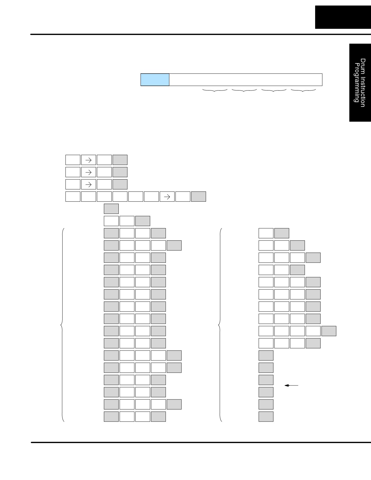
Using the DRUM entry chart (two pages before), we show the method of entry for the
basic time/event drum instruction. First, we convert the output pattern for each step
to the equivalent hex number, as shown in the following example.
Step 1
Outputs:
f f f f
F f f F f f f F F f F f
- converts to:
15
0
0
9
1
A
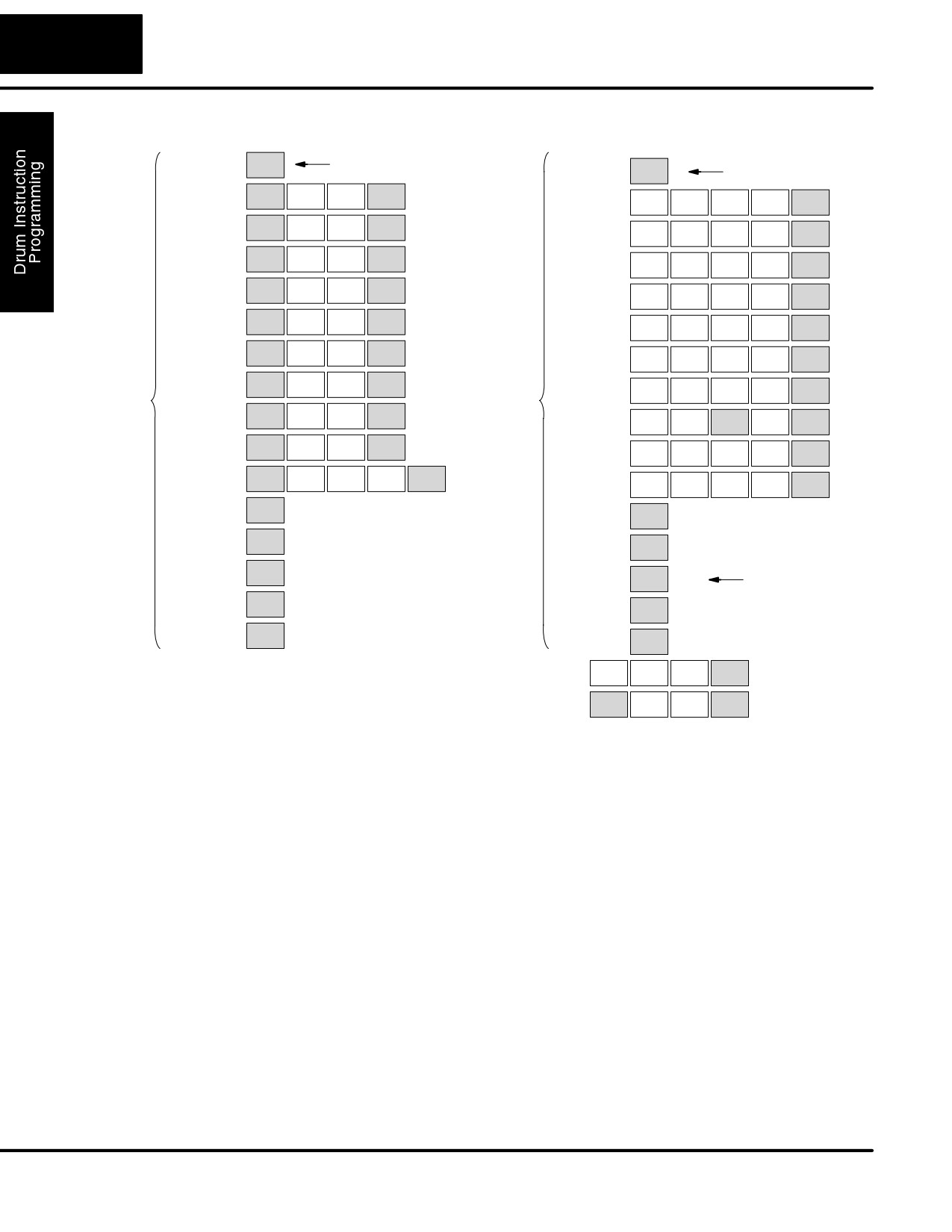
The following diagram shows the method for entering the previous EDRUM example
on the HHP. The default entries of the form are in parenthesis. After the drum
instruction entry (on the fourth row), the remaining keystrokes over-write the
numeric portion of each default DEF statement. NOTE: Drum editing requires
Handheld Programmer firmware version 1.7 or later.
Handheld Programmer Keystrokes
$
A
NOTE: You may use the NXT and PREV keys
Start
ENT
STR
0
to skip past entries for unused outputs or steps.
$
B
Jog
ENT
STR
1
$
C
Reset
ENT
STR
2
E
D
R
U
M
A
Drum Inst.
SHFT
ENT
4
3
ORN
ISG
ORST
0
Preset Step
( DEF K0001)
NEXT
G
E
Handheld Programmer Keystrokes cont’d
Time Base
( DEF K0000 )
NEXT
6
4
C
H
F
1
( DEF 0000 )
SHFT
NEXT
1
( DEF K0000 )
NEXT
2
7
5
C
B
A
C
A
( DEF 0000 )
SHFT
NEXT
( DEF K0000 )
NEXT
2
1
0
2
0
Y
B
B
F
A
( DEF 0000 )
SHFT
NEXT
( DEF K0000 )
NEXT
MLS
1
1
5
0
Y
E
E
F
( DEF 0000 )
SHFT
NEXT
( DEF K0000 )
NEXT
MLS
4
4
5
Y
F
B
I
A
( DEF 0000 )
SHFT
NEXT
( DEF K0000 )
NEXT
MLS
5
1
8
0
Y
G
J
C
D
( DEF 0000 )
SHFT
NEXT
( DEF K0000 )
NEXT
MLS
6
9
2
3
C
E
B
C
A
( DEF 0000 )
SHFT
NEXT
( DEF K0000 )
NEXT
2
4
1
2
0
C
C
I
G
E
( DEF 0000 )
SHFT
NEXT
NEXT
2
2
Counts/
( DEF K0000 )
8
6
4
Outputs
Y
A
Step
B
C
A
A
( DEF 0000 )
SHFT
NEXT
( DEF K0000 )
NEXT
MLS
0
1
2
0
0
Y
C
E
A
A
( DEF 0000 )
SHFT
NEXT
( DEF K0000 )
NEXT
MLS
2
4
0
0
C
B
E
( DEF 0000 )
SHFT
NEXT
( DEF K0000 )
NEXT
2
1
4
C
D
A
( DEF 0000 )
SHFT
NEXT
( DEF K0000 )
NEXT
2
3
0
( DEF 0000 )
SHFT
Y
G
NEXT
( DEF K0000 )
NEXT
MLS
6
skip over
Y
H
unused steps
( DEF 0000 )
SHFT
NEXT
( DEF K0000 )
NEXT
MLS
7
C
D
E
( DEF 0000 )
SHFT
NEXT
( DEF K0000 )
NEXT
2
3
4
Y
B
16
( DEF 0000 )
SHFT
NEXT
16( DEF K0000 )
NEXT
MLS
1
(Continued on next page)
DL105 PLC User Manual, 2nd Edition, Rev. A
6-16
Drum Instruction Programming
Handheld Programmer Keystrokes cont’d
Handheld Programmer Keystrokes cont’d
1
( DEF 0000 )
NEXT
skip over unused event
1
( DEF K0000 )
NEXT
step 1 pattern = 0000
( DEF 0000 )
Y
E
SHFT
NEXT
J
I
B
C
MLS
4
( DEF K0000 )
NEXT
9
8
1
2
X
B
( DEF 0000 )
SHFT
NEXT
C
I
J
E
SET
1
( DEF K0000 )
NEXT
2
8
9
4
( DEF 0000 )
SHFT
X
C
NEXT
E
E
H
G
SET
2
( DEF K0000 )
NEXT
4
4
7
6
C
A
( DEF 0000 )
SHFT
NEXT
F
B
G
J
2
0
( DEF K0000 )
NEXT
5
1
6
9
C
B
( DEF 0000 )
SHFT
NEXT
J
D
E
D
2
1
( DEF K0000 )
NEXT
9
3
4
3
X
A
( DEF 0000 )
SHFT
NEXT
E
E
I
G
SET
0
( DEF K0000 )
NEXT
4
4
8
6
X
F
( DEF 0000 )
SHFT
NEXT
J
E
F
J
SET
5
Output
( DEF K0000 )
NEXT
9
4
5
9
Events
X
D
Pattern
( DEF 0000 )
SHFT
NEXT
D
I
A
SET
3
( DEF K0000 )
SHFT
NEXT
3
8
0
( DEF 0000 )
SHFT
Y
H
NEXT
F
I
G
E
MLS
7
( DEF K0000 )
NEXT
5
8
6
4
C
C
A
( DEF 0000 )
SHFT
NEXT
I
E
E
H
2
2
0
( DEF K0000 )
NEXT
8
4
4
7
( DEF 0000 )
NEXT
( DEF K0000 )
NEXT
( DEF 0000 )
NEXT
( DEF K0000 )
NEXT
( DEF 0000 )
NEXT
( DEF K0000 )
NEXT
unused steps
( DEF 0000 )
NEXT
( DEF K0000 )
NEXT
16
( DEF 0000 )
NEXT
16
( DEF K0000 )
NEXT
$
GY
A
NEXT
STR
CNT
0
Last rung
Y
A
SHFT
NEXT
MLS
0
NOTE: You may use the NXT and PREV keys
to skip past entries for unused outputs or steps.
DL105 PLC User Manual, 2nd Edition, Rev. A
7
RLLPLUS
Stage Programming
In This Chapter
Ċ Introduction to Stage Programming
Ċ Learning to Draw State Transition Diagrams
Ċ Using the Stage Jump Instruction for State Transitions
Ċ Stage Program Example: Toggle On/Off Lamp Controller
Ċ Four Steps to Writing a Stage Program
Ċ Stage Program Example: A Garage Door Opener
Ċ Stage Program Design Considerations
Ċ RLLPLUS Stage Instructions
Ċ Questions and Answers about Stage Programs
7-2
RLLPLUS Stage Programming
Introduction to Stage Programming
Stage Programming provides a way to organize and program complex applications
with relative ease, when compared to purely relay ladder logic (RLL) solutions.
Stage programming does not replace or negate the use of traditional boolean ladder
programming. This is why Stage Programming is also called RLLPLUS. You won’t
have to discard any training or experience you already have. Stage programming
simply allows you to divide and organize a RLL program into groups of ladder
instructions called stages. This allows quicker and more intuitive ladder program
development than traditional RLL alone provides.
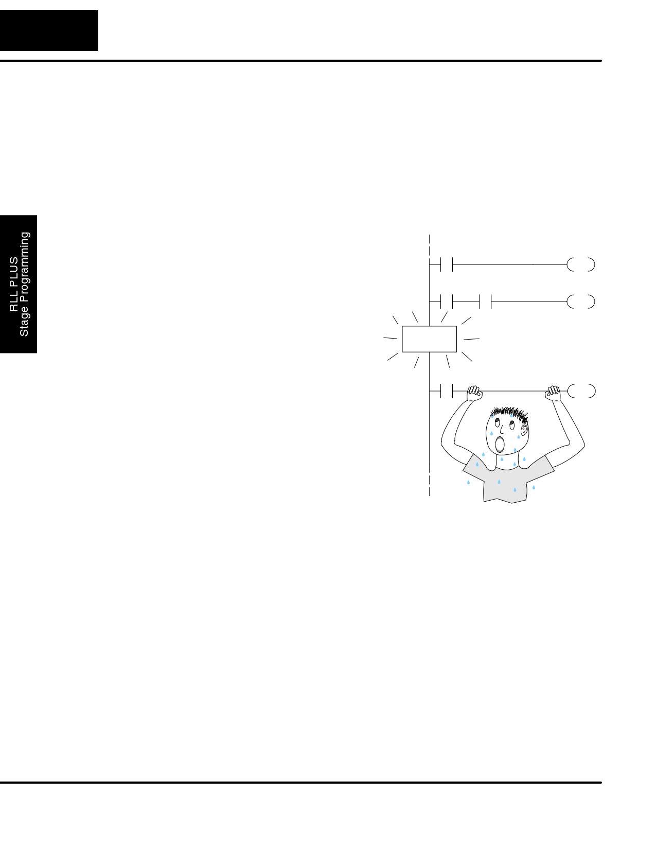
Overcoming
Many PLC programmers in the industry
“Stage Fright”
have become comfortable using RLL for
X0
C0
every PLC program they write... but often
RST
remain skeptical or even fearful of learning
new techniques such as stage
X4
C1
Y0
programming. While RLL is great at
SET
solving boolean logic relationships, it has
disadvantages as well:
STAGE!
S Large programs can become almost
unmanageable, because of a lack of
structure.
X3
Y2
S In RLL, latches must be tediously
OUT
created from self-latching relays.
S When a process gets stuck, it is
difficult to find the rung where the
error occurred.
S Programs become difficult to modify
later, because they do not intuitively
resemble the application problem
they are solving.
It’s easy to see that these inefficiencies consume a lot of additional time, and time is
money. Stage programming overcomes these obstacles! We believe a few
moments of studying the stage concept is one of the greatest investments in
programming speed and efficiency a PLC programmer can make!
So, we encourage you to study stage programming and add it to your “toolbox” of
programming techniques. This chapter is designed as a self-paced tutorial on stage
programming. For best results:
S Start at the beginning and do not skip over any sections.
S Study each stage programming concept by working through each
example. The examples build progressively on each other.
S Read the stage Questions and Answers at the end of the chapter for a
quick review.
DL105 PLC User Manual, 2nd Edition, Rev. A
7-3
RLLPLUS Stage Programming
Learning to Draw State Transition Diagrams
Introduction to
Those familiar with ladder program
Process States
execution know that the CPU must scan
Ladder
Inputs
Outputs
the ladder program repeatedly, over and
Program
over. Its three basic steps are:
1. Read the inputs
PLC Scan
2. Execute the ladder program
3. Write the outputs
1) Read Execute
Write
The benefit is that a change at the inputs
2) Read
Execute
Write
can affect the outputs in just a few
3) Read
(etc
)
milliseconds.
Most manufacturing processes consist of a series of activities or conditions , each
lasting for several seconds. minutes, or even hours. We might call these “process
states”, which are either active or inactive at any particular time. A challenge for RLL
programs is that a particular input event may last for just a brief instant. We typically
create latching relays in RLL to preserve the input event in order to maintain a
process state for the required duration.
We can organize and divide ladder logic into sections called “stages”, representing
process states. But before we describe stages in detail, we will reveal the secret to
understanding stage programming: state transition diagrams.
The Need for State
Sometimes we need to forget about the scan nature of PLCs, and focus our thinking
Diagrams
toward the states of the process we need to identify. Clear thinking and concise
analysis of an application gives us the best chance at writing efficient, bug-free
programs. State diagrams are just a tool to help us draw a picture of our process!
You’ll discover that if we can get the picture right, our program will also be right!
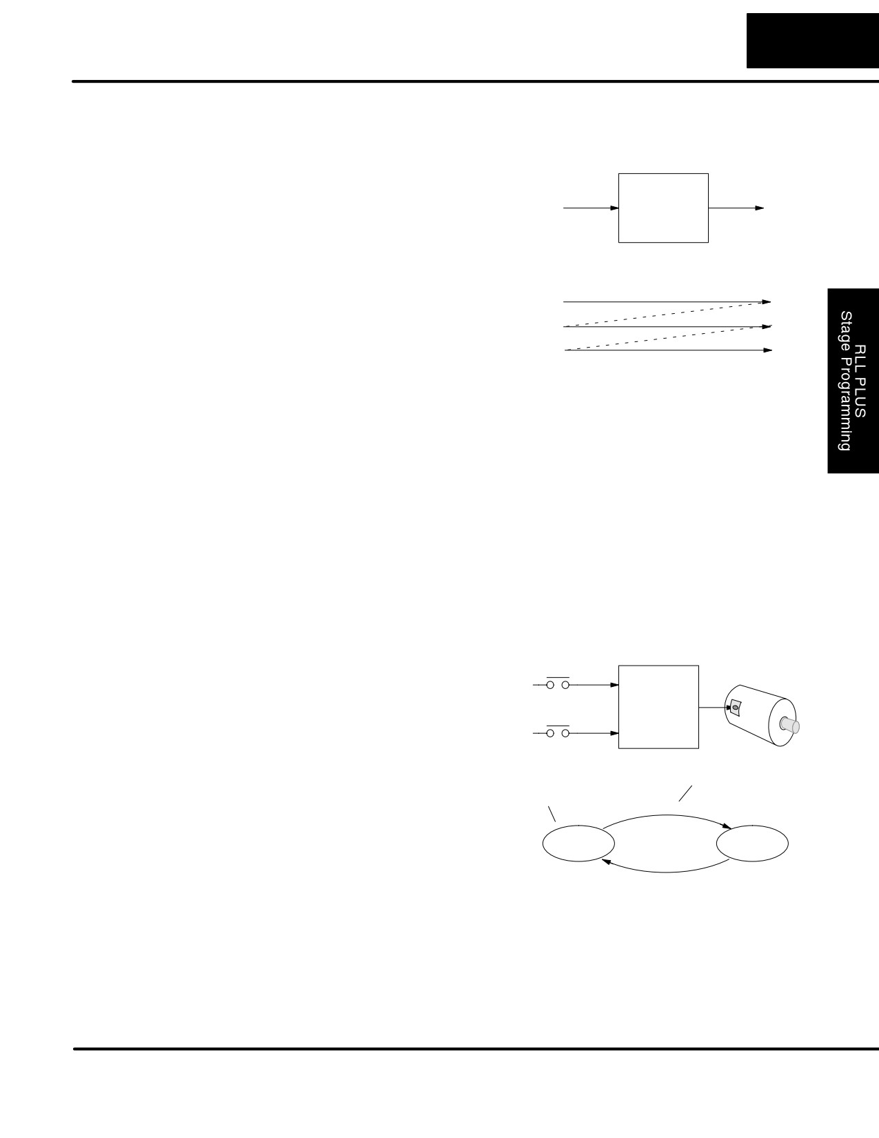
A 2-State Process
Consider the simple process shown to the
Inputs
Outputs
right, which controls an industrial motor.
On
We will use a green momentary SPST
X0
Motor
pushbutton to turn the motor on, and a red
Ladder
Y0
one to turn it off. The machine operator will
Off
Program
X1
press the appropriate pushbutton for just a
second or so. The two states of our
process are ON and OFF.
Transition condition
The next step is to draw a state transition
State
diagram, as shown to the right. It shows
X0
the two states OFF and ON, with two
transition lines in-between. When the
OFF
ON
event X0 is true, we transition from OFF to
X1
ON. When X1 is true, we transition from
ON to OFF.
Output equation: Y0 = ON
If you’re following along, you are very close to grasping the concept and the
problem-solving power of state transition diagrams. The output of our controller is
Y0, which is true any time we are in the ON state. In a boolean sense, Y0=ON state.
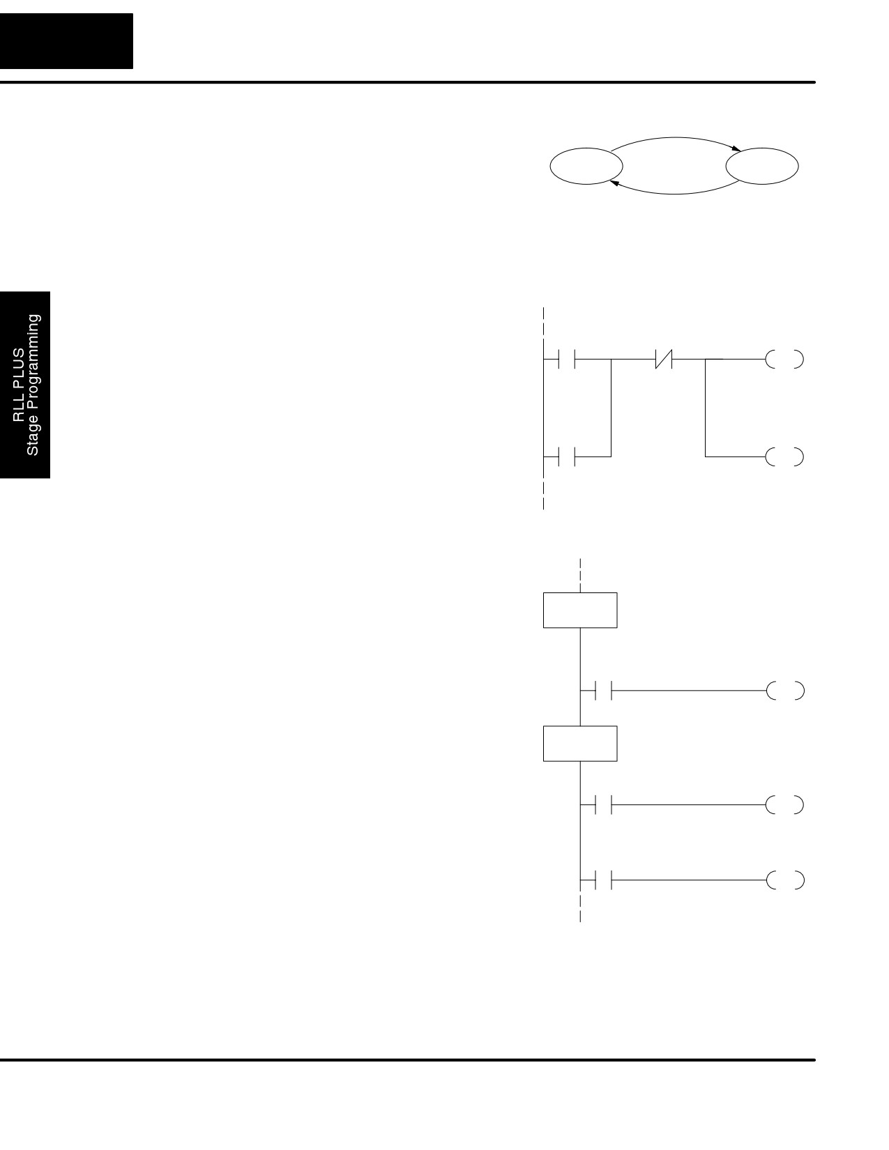
Next, we will implement the state diagram first as RLL, then as a stage program. This
will help you see the relationship between the two methods in problem solving.
DL105 PLC User Manual, 2nd Edition, Rev. A
7-4
RLLPLUS Stage Programming
The state transition diagram to the right is
X0
a picture of the solution we need to create.
The beauty of it is this: it expresses the
OFF
ON
problem
independently
of
the
X1
programming language we may use to
realize it. In other words, by drawing the
diagram we have already solved the
Output equation: Y0 = ON
control problem!
First, we’ll translate the state diagram to traditional RLL. Then we’ll show how easy it
is to translate the diagram into a stage programming solution.
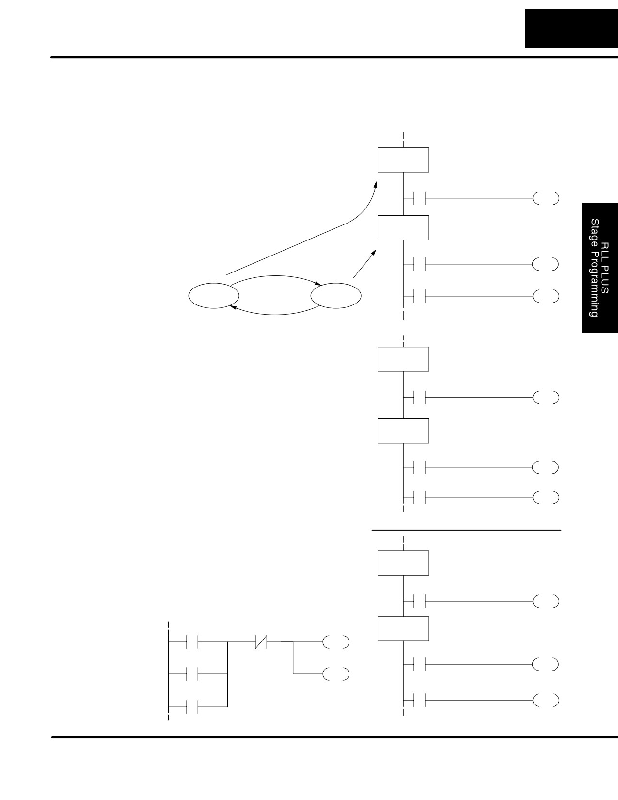
RLL Equivalent
The RLL solution is shown to the right. It
Set
Reset
Latch
consists of a self-latching control relay,
X0
X1
C0
C0. When the On pushbutton (X0) is
OUT
pressed, output coil C0 turns on and the
C0 contact on the second row latches
itself on. So, X0 sets the latch C0 on, and
Latch
Output
it remains on after the X0 contact opens.
The motor output Y0 also has power flow,
C0
Y0
so the motor is now on.
OUT
When the Off pushbutton (X1) is pressed,
it opens the normally-closed X1 contact,
which resets the latch. Motor output Y0
turns off when the latch coil C0 goes off.
Stage Equivalent
The stage program solution is shown to
the right. The two inline stage boxes S0
and S1 correspond to the two states OFF
SG
and ON. The ladder rung(s) below each
S0
OFF State
stage box belong to each respective
stage. This means that the PLC only has
Transition
to scan those rungs when the
X0
S1
corresponding stage is active!
JMP
For now, let’s assume we begin in the OFF
State, so stage S0 is active. When the On
SG
pushbutton
(X0) is pressed, a stage
ON State
S1
transition occurs. The JMP S1 instruction
Output
executes, which simply turns off the stage
SP1
Always on
Y0
bit S0 and turns on stage bit S1. So on the
OUT
next PLC scan, the CPU will not execute
stage S0, but will execute stage S1!
Transition
In the On State (stage S1), we want the
X1
S0
motor to always be on. The special relay
JMP
contact SP1 is defined as always on, so Y0
turns the motor on.
When the Off pushbutton (X1) is pressed, a transition back to the Off State occurs.
The JMP S0 instruction executes, which simply turns off the stage bit S1 and turns on
stage bit S0. On the next PLC scan, the CPU will not execute stage S1, so the motor
output Y0 will turn off. The Off state (stage 0) will be ready for the next cycle.
DL105 PLC User Manual, 2nd Edition, Rev. A
7-5
RLLPLUS Stage Programming
Let’s Compare
Right now, you may be thinking
“I don’t see the big advantage to Stage
Programming... in fact, the stage program is longer than the plain RLL program”.
Well, now is the time to exercise a bit of faith. As control problems grow in complexity,
stage programming quickly out-performs RLL in simplicity, program size, etc.
For example, consider the diagram below.
Notice how easy it is to correlate the OFF
SG
and ON states of the state transition
S0
OFF State
diagram below to the stage program at the
right. Now, we challenge anyone to easily
X0
S1
identify the same states in the RLL
JMP
program on the previous page!
SG
ON State
S1
SP1
Y0
OUT
X0
X1
S0
OFF
ON
JMP
X1
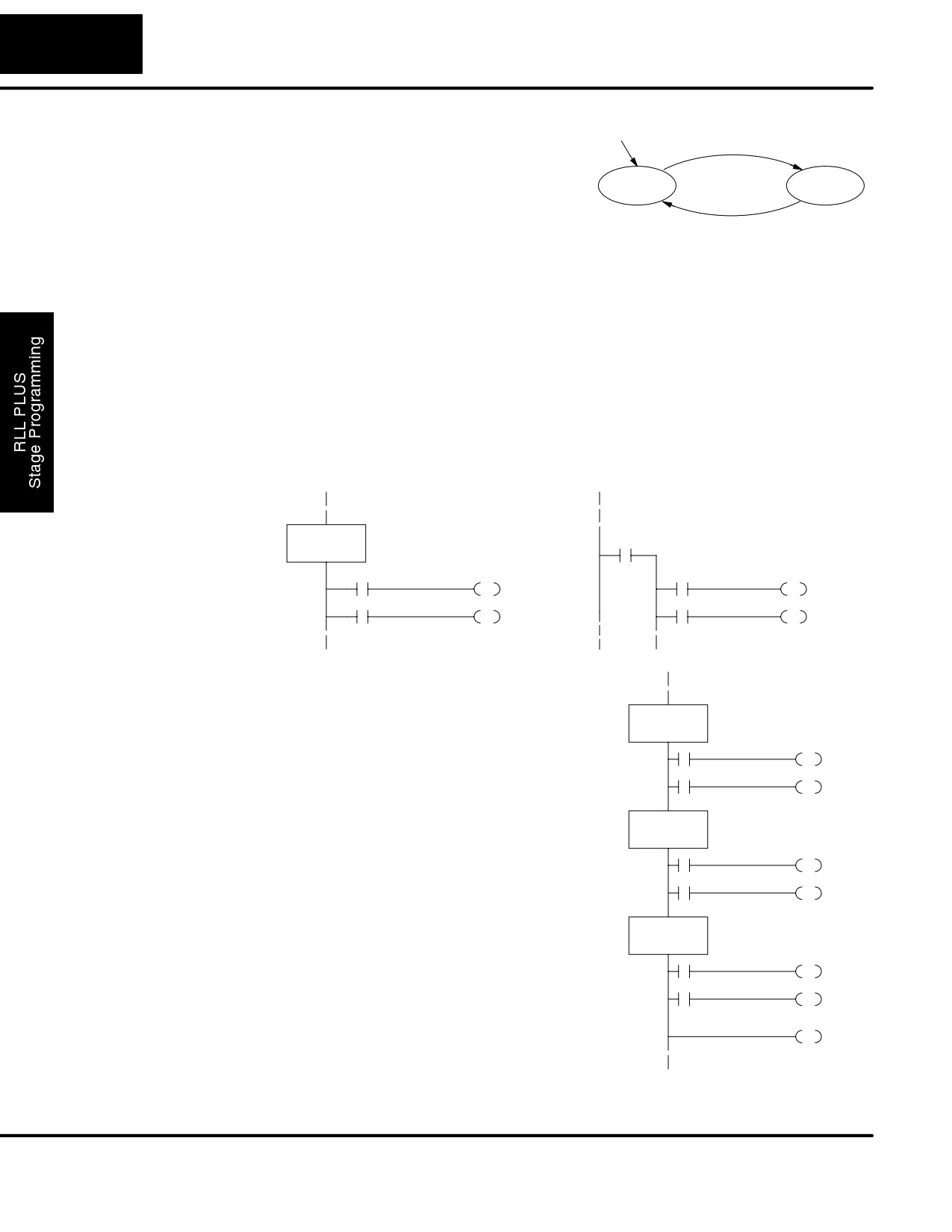
Initial Stages
At powerup and Program-to-Run Mode
Powerup in OFF State
transitions, the PLC always begins with all
ISG
normal stages (SG) off. So, the stage
S0
Initial Stage
programs shown so far have actually had
X0
S1
no way to get started (because rungs are
not scanned unless their stage is active).
JMP
Assume that we want to always begin in
the Off state (motor off), which is how the
SG
S1
RLL program works. The Initial Stage
(ISG) is defined to be active at powerup. In
SP1
Y0
the modified program to the right, we have
OUT
changed stage S0 to the ISG type. This
X1
S0
ensures the PLC will scan contact X0 after
powerup, because Stage S0 is active.
JMP
After powerup, an Initial Stage (ISG)
works just like any other stage!
We can change both programs so that the
Powerup in ON State
motor is ON at powerup. In the RLL below,
SG
we must add a first scan relay SP0,
S0
latching C0 on. In the stage example to the
right, we simply make Stage S1 an initial
X0
S1
stage (ISG) instead of S0.
JMP
Powerup in ON State
ISG
X0
X1
C0
Initial Stage
S1
OUT
SP1
Y0
C0
Y0
OUT
OUT
X1
S0
SP0
JMP
First Scan
DL105 PLC User Manual, 2nd Edition, Rev. A
7-6
RLLPLUS Stage Programming
We can mark our desired powerup state
Powerup
as shown to the right, which helps us
X0
remember to use the appropriate Initial
Stages when creating a stage program. It
OFF
ON
is permissible to have as many initial
X1
stages as the process requires.
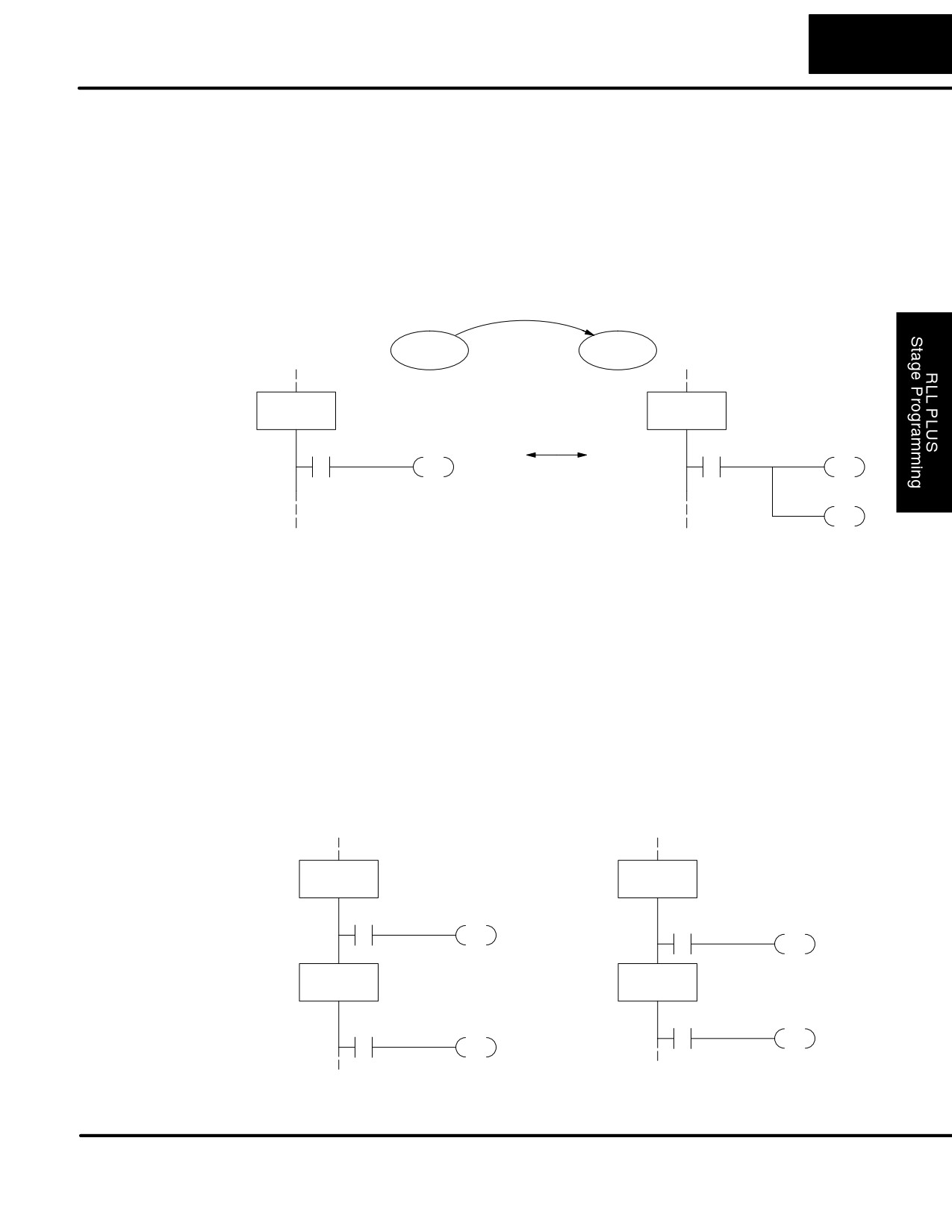
You may recall that a stage is just a section of ladder program which is either active or
What Stage Bits Do
inactive at a given moment. All stage bits (S0 to S77) reside in the PLC’s image
register as individual status bits. Each stage bit is either a boolean 0 or 1 at any time.
Program execution always reads ladder rungs from top to bottom, and from left to
right. The drawing below shows the effect of stage bit status. The ladder rungs below
the stage instruction continuing until the next stage instruction or the end of program
belong to stage 0. Its equivalent operation is shown on the right. When S0 is true, the
two rungs have power flow.
S If Stage bit S0 = 0, its ladder rungs are not scanned (executed).
S If stage bit S0 = 1, its ladder rungs are scanned (executed).
Actual Program Appearance
Functionally Equivalent Ladder
SG
S0
S0
(includes all rungs in stage)
Stage Instruction
The inline stage boxes on the left power
Characteristics
rail divide the ladder program rungs into
stages. Some stage rules are:
SG
S0
S Execution - Only logic in active
stages are executed on any scan.
S Transitions - Stage transition
instructions take effect on the next
occurrence of the stages involved.
SG
S1
S Octal numbering - Stages are
numbered in octal, like I/O points,
etc. So “S8” is not valid.
S Total Stages - The DL105 offers up
to 256 stages (S0 to S377 in octal).
SG
S2
S No duplicates - Each stage number
is unique and can be used just once.
S Any order - You can skip numbers
and sequence the stage numbers in
any order.
END
S Last Stage - the last stage in the
ladder program includes all rungs
from its stage box until the end coil.
DL105 PLC User Manual, 2nd Edition, Rev. A
7-7
RLLPLUS Stage Programming
Using the Stage Jump Instruction for State Transitions
Stage Jump, Set,
The stage JMP instruction we have used deactivates the stage in which the
and Reset
instruction occurs, while activating the stage in the JMP instruction. Refer to the
Instructions
state transition shown below. When contact X0 energizes, the state transition from
S0 to S1 occurs. The two stage examples shown below are equivalent. So, the stage
Jump instruction is equal to a Stage Reset of the current stage, plus a Stage Set
instruction for the stage to which we want to transition.
X0
S0
S1
SG
SG
S0
S0
Equivalent
X0
S1
X0
S0
JMP
RST
S1
SET
Please Read Carefully - The jump instruction is easily misunderstood. The “jump”
does not occur immediately like a GOTO or GOSUB program control instruction
when executed. Here’s how it works:
S The jump instruction resets the stage bit of the stage in which it occurs.
All rungs in the stage still finish executing during the current scan, even
if there are other rungs in the stage below the jump instruction!
S The reset will be in effect on the following scan, so the stage that
executed the jump instruction previously will be inactive and bypassed.
S The stage bit of the stage named in the Jump instruction will be set
immediately, so the stage will be executed on its next occurrence. In the
left program shown below, stage S1 executes during the same scan as
the JMP S1 occurs in S0. In the example on the right, Stage S1
executes on the next scan after the JMP S1 executes, because stage
S1 is located above stage S0.
SG
SG
Executes on next
S0
S1
scan after Jmp
X0
S1
S1
Y0
JMP
OUT
SG
Executes on same
SG
S1
scan as Jmp
S0
X0
S1
S1
Y0
JMP
OUT
Note: Assume we start with Stage 0 active and stage 1 inactive for both examples.
DL105 PLC User Manual, 2nd Edition, Rev. A
7-8
RLLPLUS Stage Programming
Stage Program Example: Toggle On/Off Lamp Controller
A 4-State Process
In the process shown to the right, we use
Inputs
Outputs
an ordinary momentary pushbutton to
control a light bulb. The ladder program
Toggle
will latch the switch input, so that we will
X0
Ladder
Y0
push and release to turn on the light, push
Program
and release again to turn it off (sometimes
called toggle function). Sure, we could just
buy a mechanical switch with the alternate
on/off action built in... However, this
Powerup
example is educational and also fun!
X0
Next we draw the state transition diagram.
OFF
ON
A typical first approach is to use X0 for
both transitions (like the example shown
X0
to the right). However, this is incorrect
Output equation: Y0 = ON
(please keep reading).
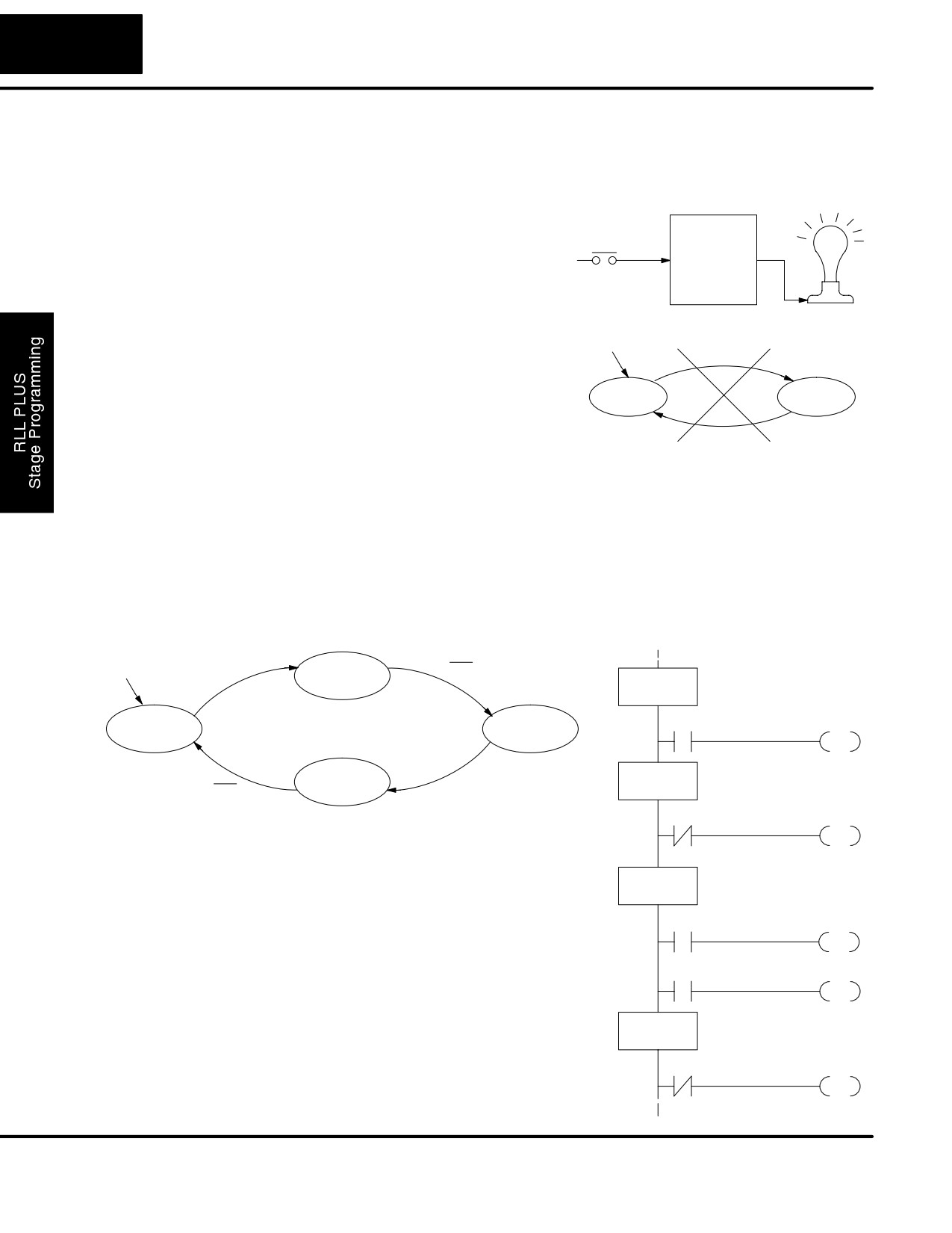
Note that this example differs from the motor example, because now we have just
one pushbutton. When we press the pushbutton, both transition conditions are met.
We would just transition around the state diagram at top speed. If implemented in
stage, this solution would flash the light on or off each scan (obviously undesirable)!
The solution is to make the the push and the release of the pushbutton separate
events. Refer to the new state transition diagram below. At powerup we enter the
OFF state. When switch X0 is pressed, we enter the Press-ON state. When it is
released, we enter the ON state. Note that X0 with the bar above it denotes X0 NOT.
Powerup
X0
Push-ON
X0
ISG
OFF State
S0
X0
S1
OFF
ON
JMP
SG
Push-OFF
Push-On State
X0
S1
X0
X0
S2
Output equation: Y0 = ON
JMP
When in the ON state, another push and
release cycle similarly takes us back to the
SG
OFF state. Now we have two unique states
ON State
S2
(OFF and ON) used when the pushbutton is
Output
released, which is what was required to solve
SP1
Y0
the control problem.
OUT
The equivalent stage program is shown to the
X0
S3
right. The desired powerup state is OFF, so
JMP
we make S0 an initial stage (ISG). In the ON
state, we add special relay contact SP1,
SG
Push-Off State
S3
which is always on.
Note that even as our programs grow more
X0
S0
complex, it is still easy to correlate the state
JMP
transition diagram with the stage program!
DL105 PLC User Manual, 2nd Edition, Rev. A
7-9
RLLPLUS Stage Programming
Four Steps to Writing a Stage Program
By now, you’ve probably noticed that we follow the same steps to solve each
example problem. The steps will probably come to you automatically if you work
through all the examples in this chapter. It’s helpful to have a checklist to guide us
through the problem solving. The following steps summarize the stage program
design procedure:
1. Write a Word Description of the application.
Describe all functions of the process in your own words. Start by listing what
happens first, then next, etc. If you find there are too many things happening at once,
try dividing the problem into more than one process. Remember, you can still have
the processes communicate with each other to coordinate their overall activity.
2. Draw the Block Diagram.
Inputs represent all the information the process needs for decisions, and outputs
connect to all devices controlled by the process.
S Make lists of inputs and outputs for the process.
S Assign I/O point numbers (X and Y) to physical inputs and outputs.
3. Draw the State Transition Diagram.
The state transition diagram describes the central function of the block diagram,
reading inputs and generating outputs.
S Identify and name the states of the process.
S Identify the event(s) required for each transition between states.
S Ensure the process has a way to re-start itself, or is cyclical.
S Choose the powerup state for your process.
S Write the output equations.
4. Write the Stage Program.
Translate the state transition diagram into a stage program.
S Make each state a stage. Remember to number stages in octal. Up to
256 total stages are available in the DL205, numbered 0 to 377 in octal.
S Put transition logic inside the stage which originates each transition (the
stage each arrow points away from).
S Use an initial stage (ISG) for any states that must be active at powerup.
S Place the outputs or actions in the appropriate stages.
You’ll notice that Steps 1 through 3 just prepare us to write the stage program in Step
4. However, the program virtually writes itself because of the preparation
beforehand. Soon you’ll be able to start with a word description of an application and
create a stage program in one easy session!
DL105 PLC User Manual, 2nd Edition, Rev. A
7-10
RLLPLUS Stage Programming
Stage Program Example: A Garage Door Opener
Garage Door
In this next stage programming example
Opener Example
we’ll create a garage door opener
controller. Hopefully most readers are
familiar with this application, and we can
have fun besides!
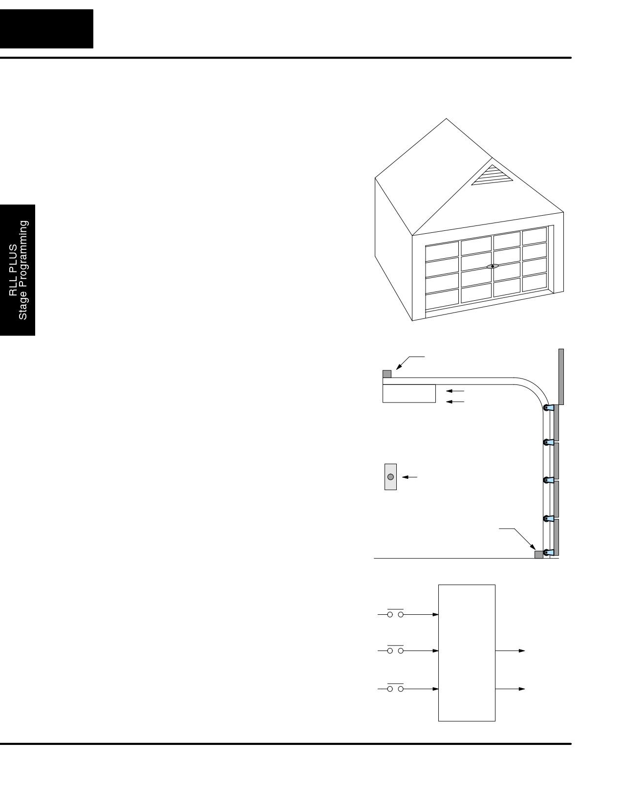
The first step we must take is to describe
how the door opener works. We will start
by achieving the basic operation, waiting
to add extra features later. Stage
programs are very easy to modify.
Our garage door controller has a motor
which raises or lowers the door on
command. The garage owner pushes and
releases a momentary pushbutton once to
raise the door. After the door is up, another
push-release cycle will lower the door.
In order to identify the inputs and outputs
Up limit switch
of the system, it’s sometimes helpful to
sketch its main components, as shown in
the door side view to the right. The door
Motor
Raise
has an up limit and a down limit switch.
Lower
Each limit switch closes only when the
door has reach the end of travel in the
corresponding direction. In the middle of
travel, neither limit switch is closed.
The motor has two command inputs: raise
Door
and lower. When neither input is active,
Command
the motor is stopped.
The door command is just a simple
pushbutton. Whether wall-mounted as
Down limit switch
shown, or a radio-remote control, all door
control commands logical OR together as
one pair of switch contacts.
Draw the Block
The block diagram of the controller is
Inputs
Outputs
Diagram
shown to the right. Input X0 is from the
Toggle
pushbutton door control. Input X1
X0
energizes when the door reaches the full
To motor:
up position. Input X2 energizes when the
Ladder
Up limit
door reaches the full down position. When
Program
X1
Y1
Raise
the door is positioned between fully up or
down, both limit switches are open.
Down limit
The controller has two outputs to drive the
X2
Y2
Lower
motor. Y1 is the up
(raise the door)
command, and Y2 is the down (lower the
door) command.
DL105 PLC User Manual, 2nd Edition, Rev. A
7-11
RLLPLUS Stage Programming
Draw the State
Now we are ready to draw the state transition diagram. Like the previous light bulb
Diagram
controller example, this application also has just one switch for the command input.
Refer to the figure below.
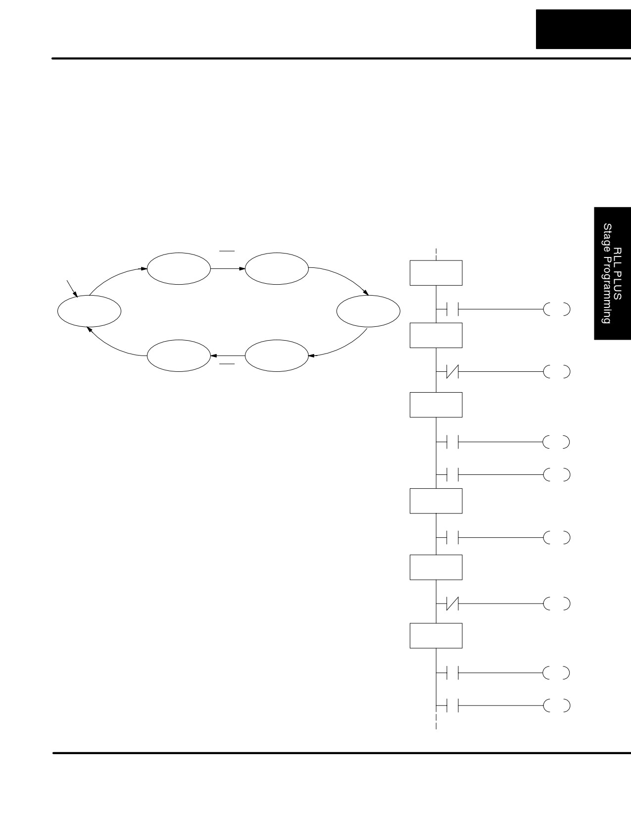
S When the door is down (DOWN state), nothing happens until X0
energizes. Its push and release brings us to the RAISE state, where
output Y1 turns on and causes the motor to raise the door.
S We transition to the UP state when the up limit switch (X1) energizes,
and turns off the motor.
S Then nothing happens until another X0 press-release cycle occurs. That
takes us to the LOWER state, turning on output Y2 to command the
motor to lower the door. We transition back to the DOWN state when the
down limit switch (X2) energizes.
X0
X0
X1
Push-UP
RAISE
ISG
Powerup
DOWN State
S0
X0
S1
DOWN
UP
JMP
SG
Push-UP State
S1
X2
LOWER
Push-DOWN
X0
X0
S2
X0
JMP
Output equations: Y1 = RAISE Y2 = LOWER
SG
RAISE State
S2
The equivalent stage program is shown to the
right. For now, we will assume the door is
SP1
Y1
down at powerup, so the desired powerup
OUT
state is DOWN. We make S0 an initial stage
X1
S3
(ISG). Stage S0 remains active until the door
JMP
control pushbutton activates. Then we
transition (JMP) to Push-UP stage, S1.
SG
UP State
S3
A push-release cycle of the pushbutton takes
us through stage S1 to the RAISE stage, S2.
X0
S4
We use the always-on contact SP1 to
JMP
energize the motor’s raise command, Y1.
When the door reaches the fully-raised
SG
Push-DOWN State
position, the up limit switch X1 activates. This
S4
takes us to the UP Stage S3, where we wait
X0
S5
until another door control command occurs.
JMP
In the UP Stage S3, a push-release cycle of
the pushbutton will take us to the LOWER
SG
Stage S5, where we activate Y2 to command
LOWER State
S5
the motor to lower the door. This continues
SP1
Y2
until the door reaches the down limit switch,
X2. When X2 closes, we transition from Stage
OUT
S5 to the DOWN stage S0, where we began.
X2
S0
NOTE: The only special thing about an initial
JMP
stage (ISG) is that it is automatically active at
powerup. Afterwards, it is just like any other.
DL105 PLC User Manual, 2nd Edition, Rev. A
7-12
RLLPLUS Stage Programming
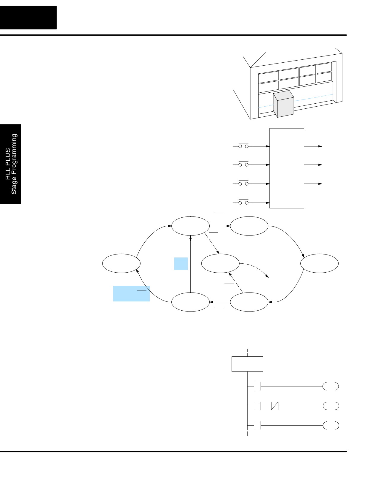
Add Safety
Next we will add a safety light feature to
Light Feature
the door opener system. It’s best to get the
main function working first as we have
done, then adding the secondary features.
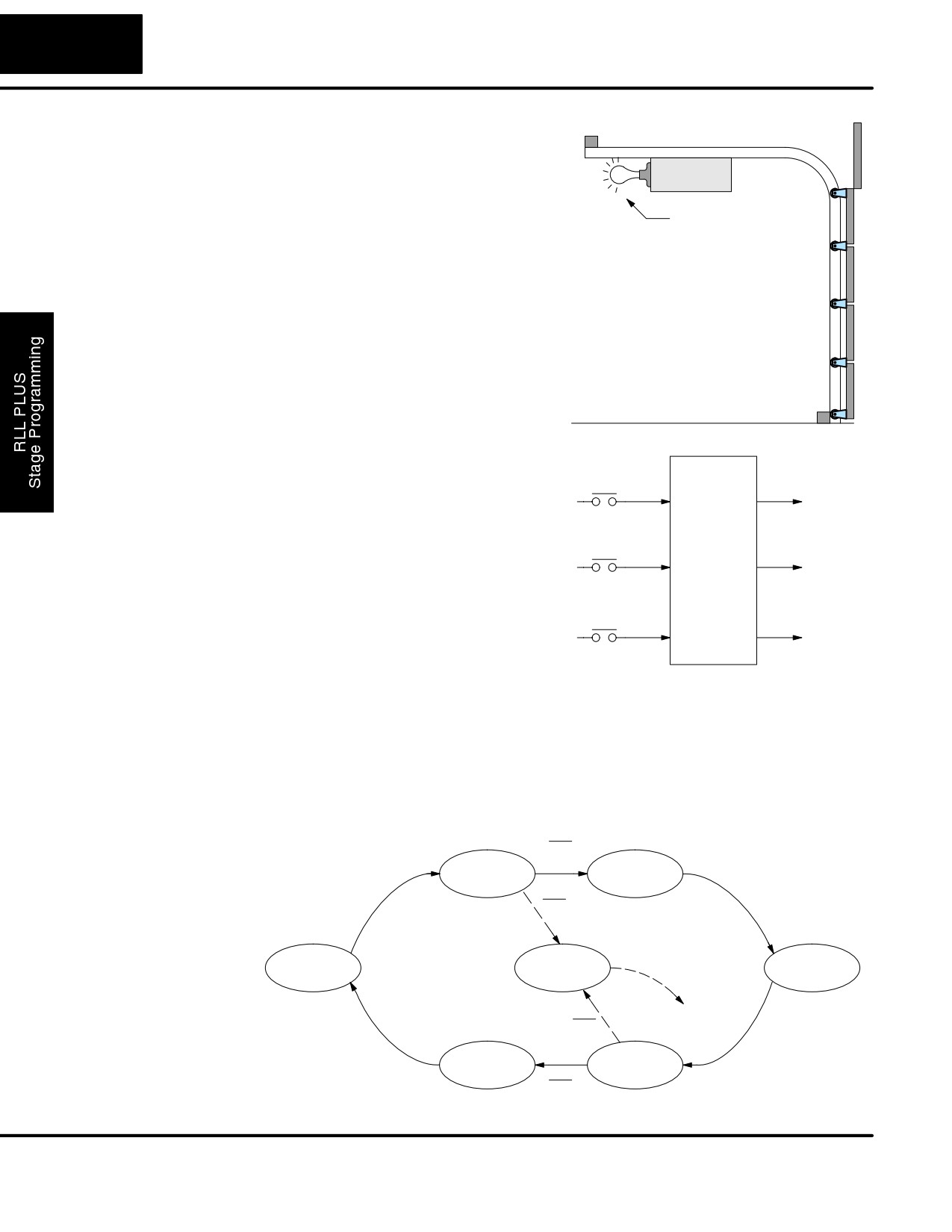
The safety light is standard on many
Safety light
commercially-available garage door
openers. It is shown to the right, mounted
on the motor housing. The light turns on
upon any door activity, remaining on for
approximately 3 minutes afterwards.
This part of the exercise will demonstrate
the use of parallel states in our state
diagram. Instead of using the JMP
instruction, we’ll use the set and reset
commands.
Modify the
To control the light bulb, we add an output
Inputs
Outputs
Block Diagram and
to our controller block diagram, shown to
Toggle
State Diagram
the right, Y3 is the light control output.
X0
Y1
Raise
In the diagram below, we add an additional
state called
“LIGHT”. Whenever the
Ladder
Up limit
garage owner presses the door control
Program
X1
Y2
switch and releases, the RAISE or
Lower
LOWER state is active and the LIGHT
state is simultaneously active. The line to
Down limit
the Light state is dashed, because it is not
X2
Y3
Light
the primary path.
We can think of the Light state as a parallel process to the raise and lower state. The
paths to the Light state are not a transition (Stage JMP), but a State Set command. In
the logic of the Light stage, we will place a three-minute timer. When it expires, timer
bit T0 turns on and resets the Light stage. The path out of the Light stage goes
nowhere, indicating the Light stage just becomes inactive, and the light goes out!
Output equations:
Y1 = RAISE
Y2 = LOWER
X0
Y3 = LIGHT
X0
Push-UP
RAISE
X1
X0
DOWN
LIGHT
T0
UP
X0
X2
LOWER
Push-DOWN
X0
X0
DL105 PLC User Manual, 2nd Edition, Rev. A
7-13
RLLPLUS Stage Programming
Using a Timer
The finished modified program is shown to
Inside a Stage
the right. The shaded areas indicate the
ISG
DOWN State
program additions.
S0
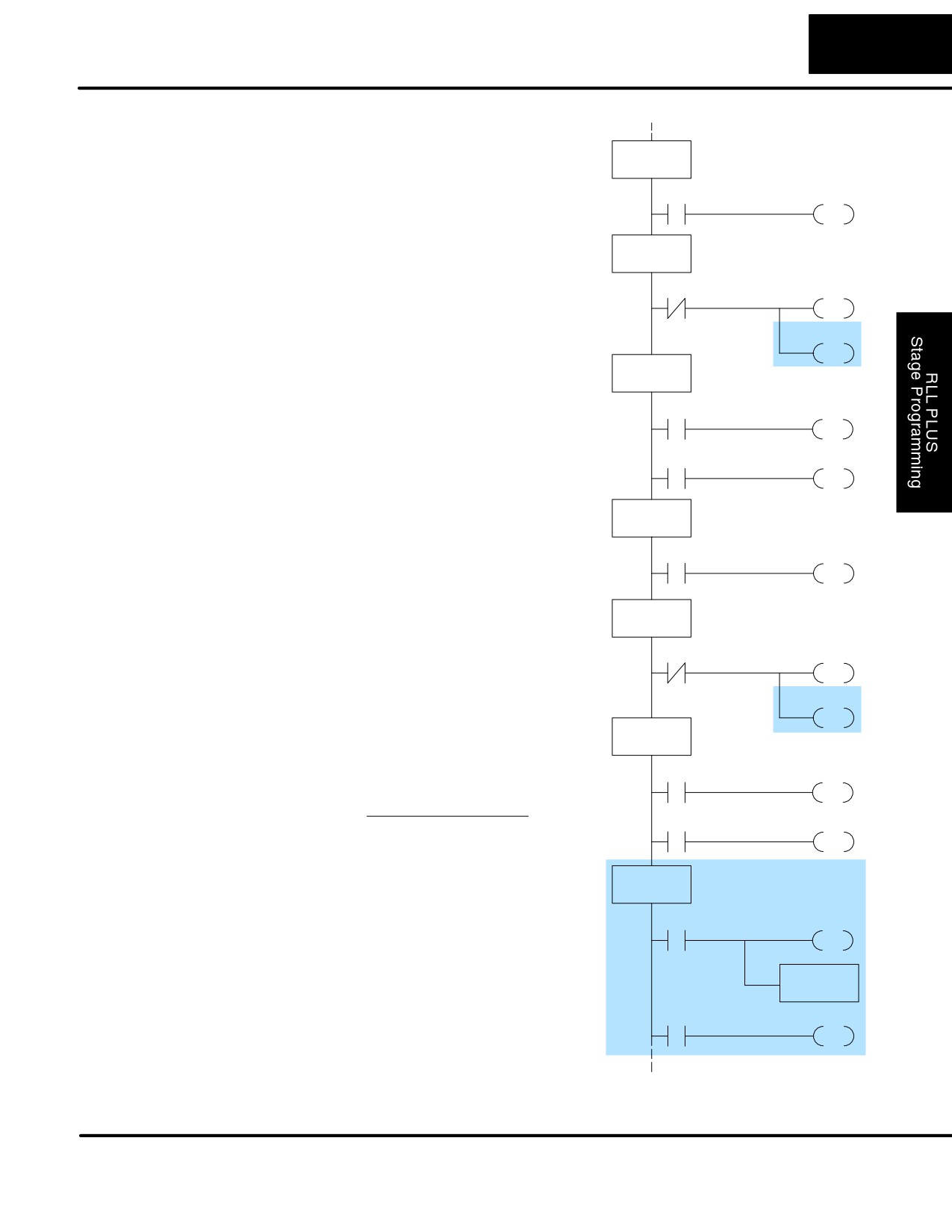
In the Push-UP stage S1, we add the Set
X0
S1
Stage Bit S6 instruction. When contact X0
JMP
opens, we transition from S1 and go to two
new active states: S2 and S6. In the
SG
Push-UP State
S1
Push-DOWN state S4, we make the same
additions. So, any time someone presses
X0
S2
the door control pushbutton, the light turns
JMP
on.
S6
Most new stage programmers would be
SET
concerned about where to place the Light
SG
S2
RAISE State
Stage in the ladder, and how to number it.
The good news is that it doesn’t matter!
SP1
Y1
S Just choose an unused stage
OUT
number, and use it for the new stage
X1
S3
and as the reference from other
JMP
stages.
S Placement in the program is not
SG
UP State
critical, so we place it at the end.
S3
You might think that each stage has to be
X0
S4
directly under the stage that transitions to
JMP
it. While it is good practice, it is not
required (that’s good, because our two
SG
Push-DOWN State
locations for the Set S6 instruction make
S4
that impossible). Stage numbers and how
X0
S5
they are used determines the transition
JMP
paths.
S6
In stage S6, we turn on the safety light by
SET
energizing Y3. Special relay contact SP1
SG
is always on. Timer T0 times at 0.1 second
S5
LOWER State
per count. To achieve 3 minutes time
SP1
Y2
period, we calculate:
OUT
3 min. x 60 sec/min
K=
X2
S0
0.1 sec/count
JMP
K=1800 counts
The timer has power flow whenever stage
SG
LIGHT State
S6
S6 is active. The corresponding timer bit
T0 is set when the timer expires. So three
SP1
Y3
minutes later, T0=1 and the instruction
OUT
Reset S6 causes the stage to be inactive.
While Stage S6 is active and the light is on,
TMR T0
K1800
stage transitions in the primary path
continue normally and independently of
T0
S6
Stage 6. That is, the door can go up, down,
RST
or whatever, but the light will be on for
precisely 3 minutes.
DL105 PLC User Manual, 2nd Edition, Rev. A
7-14
RLLPLUS Stage Programming
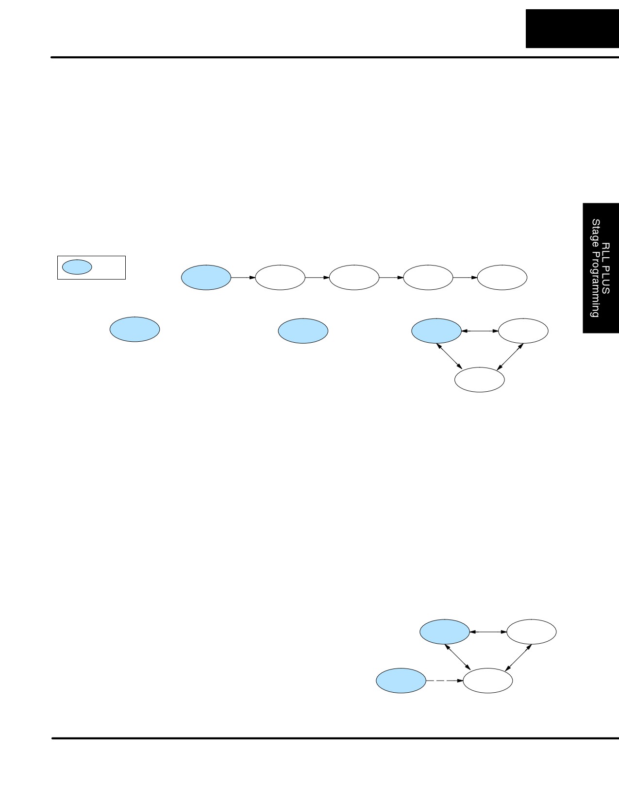
Add Emergency
Some garage door openers today will
Stop Feature
detect an object under the door. This halts
further lowering of the door. Usually
implemented
with
a
photocell
(“electric-eye”), a door in the process of
being lowered will halt and begin raising.
We will define our safety feature to work in
this way, adding the input from the
photocell to the block diagram as shown to
the right. X3 will be on if an object is in the
path of the door.
Inputs
Outputs
Next, we make a simple addition to the
Toggle
state transition diagram, shown in shaded
X0
Y1
Raise
areas in the figure below. Note the new
Up limit
transition path at the top of the LOWER
Ladder
X1
Y2
state. If we are lowering the door and
Program
Lower
detect an obstruction (X3), we then jump
Down limit
to the Push-UP State. We do this instead
X2
Y3
Light
of jumping directly to the RAISE state, to
Obstruction
give the Lower output Y2 one scan to turn
X3
off, before the Raise output Y1 energizes.
X0
X0
Push-UP
RAISE
X1
X0
DOWN
X3
LIGHT
T0
UP
X0
X2 and
X3
LOWER
Push-DOWN
X0
X0
Exclusive
It is theoretically possible that the down limit (X2) and the obstruction input (X3)
Transitions
could energize at the same moment. In that case, we would “jump” to the Push-UP
and DOWN states simultaneously, which does not make sense.
Instead, we give priority to the obstruction
by changing the transition condition to the
SG
DOWN state to [X2 AND NOT X3]. This
S5
LOWER State
ensures the obstruction event has the
SP1
Y2
priority. The modifications we must make
OUT
to the LOWER stage (S5) logic are shown
to the right. The first rung remains
to Push-UP
X2
X3
S0
unchanged. The second and third rungs
JMP
implement the transitions we need. Note
the opposite relay contact usage for X3,
X3
to DOWN
S2
which ensures the stage will execute only
JMP
one of the JMP instructions.
DL105 PLC User Manual, 2nd Edition, Rev. A
7-15
RLLPLUS Stage Programming
Stage Program Design Considerations
Stage Program
The examples so far in this chapter used one self-contained state diagram to
Organization
represent the main process. However, we can have multiple processes
implemented in stages, all in the same ladder program. New stage programmers
sometimes try to turn a stage on and off each scan, based on the false assumption
that only one stage can be on at a time. For ladder rungs that you want to execute
each scan, just put them in a stage that is always on.
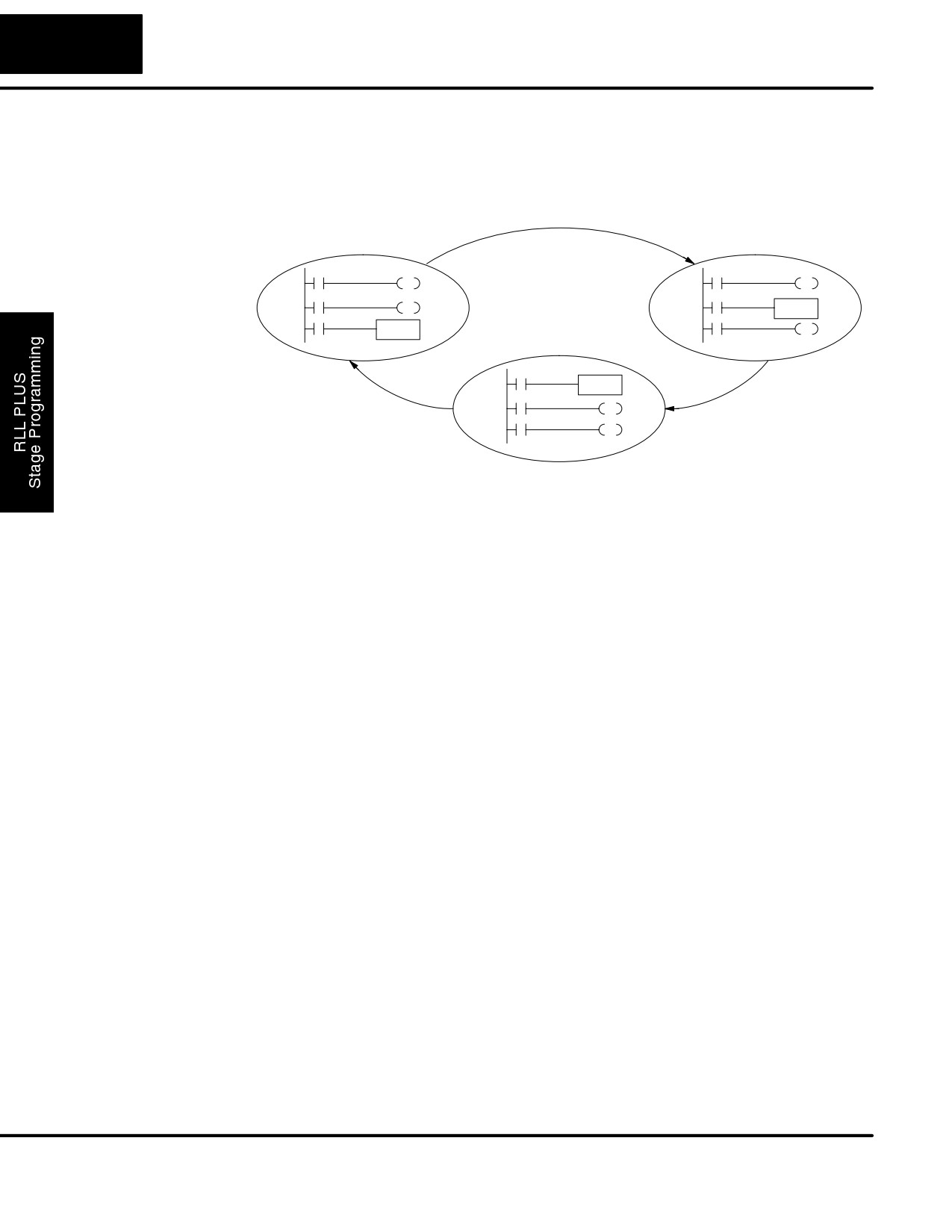
The following figure shows a typical application. During operation, the primary
manufacturing activity Main Process, Powerup Initialization, E-Stop and Alarm
Monitoring, and Operator Interface are all running. At powerup, three initial stages
shown begin operation.
Main Process
XXX
= ISG
Idle
Fill
Agitate
Rinse
Spin
Powerup Initialization
E-Stop and Alarm Monitoring
Operator Interface
Powerup
Monitor
Control
Recipe
Status
In a typical application, the separate stage sequences above operate as follows:
S Powerup Initialization - This stage contains ladder rung tasks done
just once at powerup. Its last rung resets the stage, so this stage is only
active for one scan (or only as many scans that are required).
S Main Process - this stage sequence controls the heart of the process
or machine. One pass through the sequence represents one part cycle
of the machine, or one batch in the process.
S E-Stop and Alarm Monitoring - This stage is always active because it
is watching for errors that could indicate an alarm condition or require an
emergency stop. It is common for this stage to reset stages in the main
process or elsewhere, in order to initialize them after an error condition.
S Operator Interface - this is another task that must always be active
and ready to respond to an operator. It allows an operator interface to
change modes, etc. independently of the current main process step.
Although we have separate processes,
Operator Interface
there can be coordination among them.
For example, in an error condition, the
Control
Recipe
Status Stage may want to automatically
switch the operator interface to the status
mode to show error information as shown
Set
Monitor
Status
to the right. The monitor stage could set
the stage bit for Status and Reset the
E-Stop and
stages Control and Recipe.
Alarm Monitoring
DL105 PLC User Manual, 2nd Edition, Rev. A
7-16
RLLPLUS Stage Programming
How Instructions We can think of states or stages as simply dividing up our ladder program as
depicted in the figure below. Each stage contains only the ladder rungs which are
Work Inside Stages
needed for the corresponding state of the process. The logic for transitioning out of a
stage is contained within that stage. It’s easy to choose which ladder rungs are active
at powerup by using an “initial” stage type (ISG).
Stage 0
Stage 1
Stage 2
Most all instructions work just like they do in standard RLL. You can think of a stage
just like a miniature RLL program which is either active or inactive.
Output Coils - As expected, output coils in active stages will turn on or off outputs
according to power flow into the coil. However, note the following:
S Outputs work as usual, provided each output reference (such as “Y3”) is
used in only one stage.
S An output can be referenced from more than one stage, as long as only
one of the stages is active at a time.
S If an output coil is controlled by more than one stage simultaneously, the
active stage nearest the bottom of the program determines the final
output status during each scan. Therefore, use the OROUT instruction
instead when you want multiple stages to have a logical OR control of
an output.
One-Shot or PD coils - Use care if you must use a Positive Differential coil in a
stage. Remember that the input to the coil must make a 0-1 transition. If the coil is
already energized on the first scan when the stage becomes active, the PD coil will
not work. This is because the 0-1 transition did not occur.
PD coil alternative: If there is a task which you want to do only once (on 1 scan), it can
be placed in a stage which transitions to the next stage on the same scan.
Counter - In using a counter inside a stage, the stage must be active for one scan
before the input to the counter makes a 0-1 transition. Otherwise, there is no real
transition and the counter will not count.
The ordinary Counter instruction does have a restriction inside stages: it may not be
reset from other stages using the RST instruction for the counter bit. However, the
special Stage Counter provides a solution (see next paragraph).
Stage Counter - The Stage Counter has the benefit that its count may be globally
reset from other stages by using the RST instruction. It has a count input, but no reset
input. This is the only difference from a standard counter.
Drum - Realize that the drum sequencer is its own process, and is a different
programming method than stage programming. If you need to use a drum with
stages, be sure to place the drum instruction in an ISG stage that is always active.
DL105 PLC User Manual, 2nd Edition, Rev. A
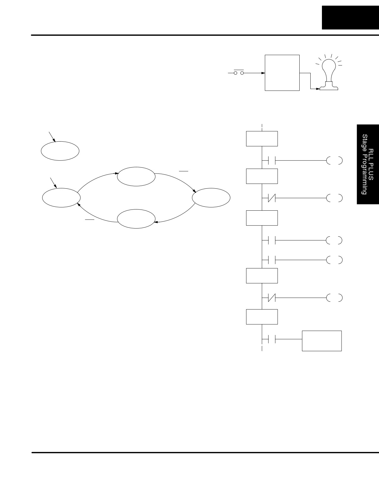
7-17
RLLPLUS Stage Programming
Using a Stage as a You may recall the light bulb on-off
Supervisory
controller example from earlier in this
Toggle
Process
chapter. For the purpose of illustration,
X0
Ladder
Y0
suppose we want to monitor the
Program
“productivity” of the lamp process, by
counting the number of on-off cycles
which occurs. This application will require
the addition of a simple counter, but the
key decision is in where to put the counter.
Powerup
ISG
OFF State
S0
Supervisor
Supervisor Process
X0
S1
JMP
Powerup
X0
SG
Push-ON
X0
Push-On State
S1
X0
S2
OFF
Main Process
ON
JMP
SG
Push-OFF
ON State
X0
S2
X0
SP1
Y0
New stage programming students will
OUT
typically try to place the counter inside one the
X0
S3
the stages of the process they are trying to
monitor. The problem with this approach is
JMP
that the stage is active only part of the time. In
SG
order for the counter to count, the count input
Push-Off State
S3
must transition from off to on at least one scan
after its stage activates. Ensuring this
X0
S0
requires extra logic that can be tricky.
JMP
In this case, we only need to add another
supervisory stage as shown above, to “watch”
ISG
Supervisor State
S4
the main process. The counter inside the
supervisor stage uses the stage bit S1 of the
S1
SGCNT CT0
main process as its count input. Stage bits
used as a contact let us monitor a process!
K5000
Note that both the Supervisor stage and the
OFF stage are initial stages. The supervisor
stage remains active indefinitely.
Stage Counter
The counter in the above example is a special Stage Counter. Note that it does not
have a reset input. The count is reset by executing a Reset instruction, naming the
counter bit (CT0 in this case). The Stage Counter has the benefit that its count may
be globally reset from other stages. The standard Counter instruction does not have
this global reset capability. You may still use a regular Counter instruction inside a
stage... however, the reset input to the counter is the only way to reset it.
DL105 PLC User Manual, 2nd Edition, Rev. A
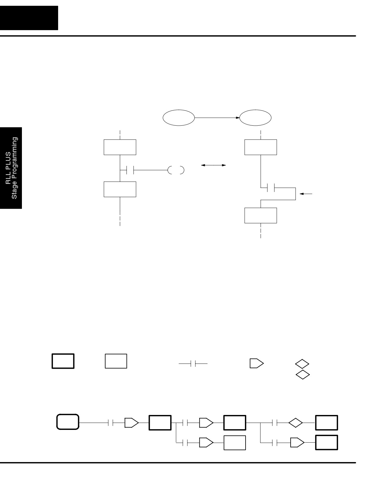
7-18
RLLPLUS Stage Programming
Power Flow
Our discussion of state transitions has shown how the stage JMP instruction makes
Transition
the current stage inactive and the next stage (named in the JMP) active. As an
Technique
alternative way to enter this in DirectSOFT32, you may use the power flow method
for stage transitions.
The main requirement is that the current stage be located directly above the next
(jump-to) stage in the ladder program. This arrangement is shown in the diagram
below, by stages S0 and S1, respectively.
X0
S0
S1
SG
SG
S0
S0
Equivalent
X0
S1
All other rungs in stage...
JMP
X0
SG
Power flow
S1
transition
SG
S1
Recall that the stage JMP instruction may occur anywhere in the current stage, and
the result is the same. However, power flow transitions (shown above) must occur as
the last rung in a stage. All other rungs in the stage will precede it. The power flow
transition method is also achievable on the handheld programmer, by simply
following the transition condition with the stage instruction for the next stage.
The power flow transition method does eliminate one stage JMP instruction, its only
advantage. However, it is not as easy to make program changes as using the stage
JMP. Therefore, we advise using stage JMP transitions for most programmers.
Stage View in
The stage View option in DirectSOFT32 will let you view the ladder program as a
DirectSOFT32
flow chart. The figure below shows the symbol convention used in the diagrams. You
may find the stage view useful as a tool to verify that your stage program has
faithfully reproduced the logic of the state transition diagram you intend to realize.
SG
Stage
Reference to
Transition
J
Jump
S Set Stage
a stage
Logic
R Reset Stage
The following diagram is a typical stage view of a ladder program containing stages.
Note the left-to-right direction of the flow chart.
ISG
SG
SG
SG
J
J
S
S0
S1
S2
S4
SG
SG
J
J
S3
S5
DL105 PLC User Manual, 2nd Edition, Rev. A
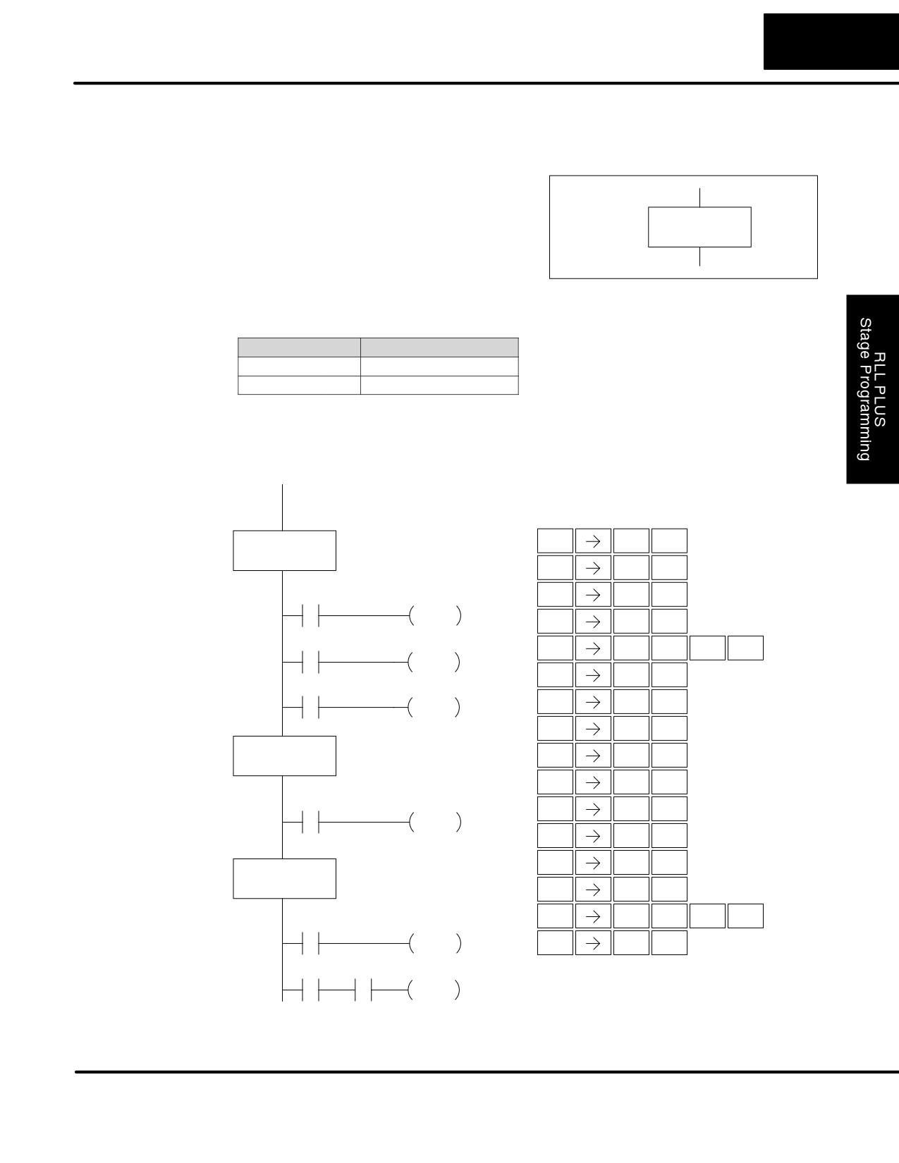
7-19
RLLPLUS Stage Programming
RLLPLUS Stage Instructions
Stage
The Stage instructions are used to create
(SG)
structured RLLPLUS programs. Stages are
program segments which can be activated
SG
by transitional logic, a jump or a set stage
S aaa
that is executed from an active stage.
Stages are deactivated one scan after
transitional logic, a jump, or a reset stage
instruction is executed.
Operand Data Type
DL130 Range
aaa
Stage
S
0-377
The following example is a simple RLLPLUS Stage program. This program utilizes an
initial stage, and jump instructions to create a structured program.
DirectSOFT32
Handheld Programmer Keystrokes
U
A
ISG
S0
ENT
ISG
0
$
A
ENT
STR
0
GX
A
X0
Y0
ENT
OUT
0
OUT
$
B
ENT
STR
1
X1
S2
X
S
C
SHFT
ENT
SET
RST
2
SET
$
F
ENT
STR
5
X5
S1
K
B
ENT
JMP
JMP
1
2
B
ENT
SG
1
SG
S1
$
C
ENT
STR
2
GX
B
ENT
OUT
1
X2
Y1
2
C
ENT
SG
2
OUT
$
G
ENT
STR
6
GX
C
ENT
SG
S2
OUT
2
$
H
ENT
STR
7
V
S
B
SHFT
ENT
X6
AND
RST
1
Y2
K
A
OUT
ENT
JMP
0
X7
S1
S0
JMP
DL105 PLC User Manual, 2nd Edition, Rev. A
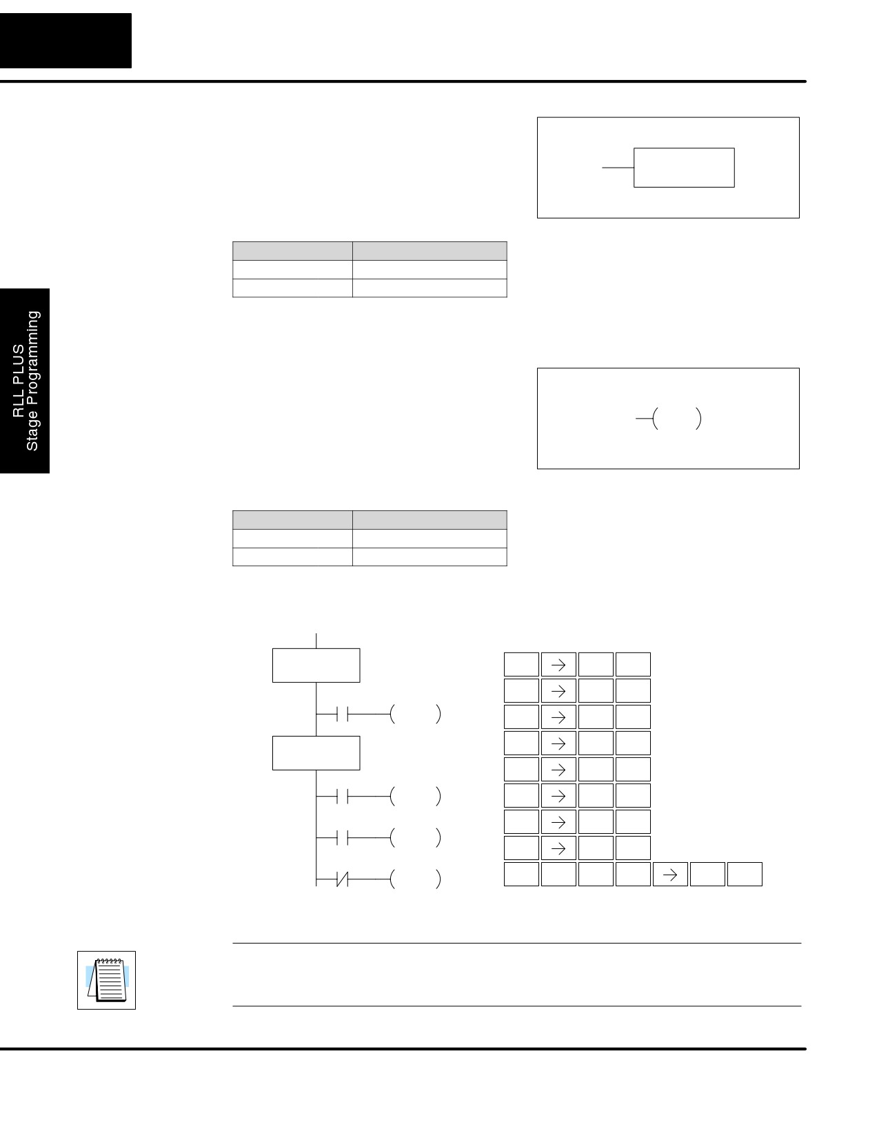
7-20
RLLPLUS Stage Programming
Initial Stage
The Initial Stage instruction is normally used
(ISG)
as the first segment of an RLLPLUS Stage
program. Multiple Initial Stages are allowed
ISG
S aaa
in a program. They will be active when the
CPU enters the Run mode allowing for a
starting point in the program.
Operand Data Type
DL130 Range
aaa
Stage
S
0-377
Initial Stages are also activated by transitional logic, a jump or a set stage executed
from an active stage.
JUMP
The Jump instruction allows the program to
(JMP)
transition from an active stage containing
S aaa
the jump instruction to another stage
JMP
(specified in the instruction). The jump
occurs when the input logic is true. The
active stage containing the Jump will
deactivate 1 scan later.
Operand Data Type
DL130 Range
aaa
Stage
S
0-377
In the following example, only stage ISG0 will be active when program execution.
begins. When X1 is on, program execution will jump from Initial Stage 0 to Stage 1.
DirectSOFT
Handheld Programmer Keystrokes
ISG
S0
U
A
ENT
ISG
0
$
B
ENT
S1
STR
1
X1
JMP
K
B
ENT
JMP
1
2
B
SG
S1
ENT
SG
1
$
C
ENT
Y5
STR
2
X2
GX
F
OUT
ENT
OUT
5
S2
$
H
ENT
X7
STR
7
JMP
K
C
ENT
JMP
2
S3
X7
N
K
D
SHFT
SHFT
ENT
JMP
TMR
JMP
3
S
S
S
NOTE: The F1-130 CPU does not have the Not Jump instruction (as does other
PLC families). You may still achieve the same result by using the Jump instruction,
while inverting the sense of contact logic that activates that instruction.
DL105 PLC User Manual, 2nd Edition, Rev. A
7-21
RLLPLUS Stage Programming
Questions and Answers about Stage Programming
We include the following commonly-asked questions about Stage Programming as
an aid to new students. All question topics are covered in more detail in this chapter.
Q. What does stage programming do that I can’t do with regular RLL programs?
A. Stages allow you to identify all the states of your process before you begin
programming. This approach is more organized, because you divide up a ladder
program into sections. As stages, these program sections are active only when they
are actually needed by the process. Most processes can be organized into a
sequence of stages, connected by event-based transitions.
Q. Isn’t a stage really just like a software subroutine?
A. No, it is very different. A subroutine is called by a main program when needed, and
executes just once before returning to the point from which it was called. A stage,
however, is part of the main program. It represents a state of the process, so an
active stage executes on every scan of the CPU until it becomes inactive.
Q. What are Stage Bits?
A. A stage bit is just a single bit in the CPU’s image register, representing the
active/inactive status of the stage in real time. For example, the bit for Stage 0 is
referenced as “S0”. If S0 = 0, then the ladder rungs in Stage 0 are bypassed (not
executed) on each CPU scan. If S0 = 1, then the ladder rungs in Stage 0 are
executed on each CPU scan. Stage bits, when used as contacts, allow one part of
your program to monitor another part by detecting stage active/inactive status.
Q. How does a stage become active?
A. There are three ways:
S If the Stage is an initial stage (ISG), it is automatically active at powerup.
S Another stage can execute a stage JMP instruction naming this stage,
which makes it active upon its next occurrence in the program.
S A program rung can execute a Set Stage Bit instruction (such as Set
S0).
Q. How does a stage become inactive?
A. There are three ways:
S Standard Stages (SG) are automatically inactive at powerup.
S A stage can execute a stage JMP instruction, resetting its Stage Bit to 0.
S Any rung in the program can execute a Reset Stage Bit instruction (such
as Reset S0).
Q. What about the power flow technique of stage transitions?
A. The power flow method of connecting adjacent stages (directly above or below in
the program) actually is the same as the stage Jump instruction executed in the
stage above, naming the stage below. Power flow transitions are more difficult to edit
in DirectSOFT32, we list them separately from two preceding questions.
DL105 PLC User Manual, 2nd Edition, Rev. A
7-22
RLLPLUS Stage Programming
Q. Can I have a stage which is active for only one scan?
A. Yes, but this is not the intended use for a stage. Instead, just make a ladder rung
active for 1 scan by including a stage Jump instruction at the bottom of the rung.
Then the ladder will execute on the last scan before its stage jumps to a new one.
Q. Isn’t a stage JMP just like a regular GOTO instruction used in software?
A. No, it is very different. A GOTO instruction sends the program execution
immediately to the code location named by the GOTO. A stage JMP simply resets
the stage Bit of the current stage, while setting the stage Bit of the stage named in the
JMP instruction. Stage bits are 0 or 1, determining the inactive/active status of the
corresponding stages. A stage JMP has the following results:
S When the JMP is executed, the remainder of the current stage’s rungs
are executed, even if they reside past(under) the JMP instruction. On
the following scan, that stage is not executed, because it is inactive.
S The stage named in the stage JMP instruction will be executed upon its
next occurrence. If located past (under) the current stage, it will be
executed on the same scan. If located before (above) the current stage,
it will be executed on the following scan.
Q. How can I know when to use stage JMP, versus a Set Stage Bit or Reset Stage Bit?
A. These instructions are used according to the state diagram topology you have
derived:
S Use a stage JMP instruction for a state transition... moving from one
state to another.
S Use a Set Stage Bit instruction when the current state is spawning a
new parallel state or stage sequence, or when a supervisory state is
starting a state sequence under its command.
S Use a Reset Bit instruction when the current state is the last state in a
sequence and its task is complete, or when a supervisory state is
ending a state sequence under its command.
Q. What is an initial stage, and when do I use it?
A. An initial stage (ISG) is automatically active at powerup. Afterwards, it works just
like any other stage. You can have multiple initial stages, if required. Use an initial
stage for ladder that must always be active, or as a starting point.
Q. Can I have place program ladder rungs outside of the stages, so they are always on?
A. It is possible, but it’s not good software design practice. Place ladder that must
always be active in an initial stage, and do not reset that stage or use a stage JMP
instruction inside it. It can start other stage sequences at the proper time by setting
the appropriate stage Bit(s).
Q. Can I have more than one active stage at a time?
A. Yes, and this is a normal occurrence for many programs. However, it is important
to organize your application into separate processes, each made up of stages. And a
good process design will be mostly sequential, with only one stage on at a time.
However, all the processes in the program may be active simultaneously.
DL105 PLC User Manual, 2nd Edition, Rev. A
8
Maintenance and
Troubleshooting
In This Chapter
Ċ Hardware System Maintenance
Ċ Diagnostics
Ċ CPU Indicators
Ċ Communications Problems
Ċ I/O Point Troubleshooting
Ċ Noise Troubleshooting
Ċ Machine Startup and Program Troubleshooting
8-2
Maintenance and Troubleshooting
Hardware System Maintenance
Standard
No regular or preventative maintenance is required for this product (there are no
Maintenance
internal batteries); however, a routine maintenance check (about every one or two
months) of your PLC and control system is good practice, and should include the
following items:
S Air Temperature - Check the air temperature in the control cabinet, so
the operating temperature range of any component is not exceeded.
S Air Filter - If the control cabinet has an air filter, clean or replace it
periodically as required.
S Fuses or breakers - verify that all fuses and breakers are intact.
S DL105 Air Vents - check that all air vents are clear. If the exterior case
needs cleaning, disconnect the input power, and carefully wipe the case
using a damp cloth. Do not let water enter the case through the air vents
and do not use strong detergents because this may discolor the case.
Diagnostics
Diagnostics
Your DL105 Micro PLC performs many pre-defined diagnostic routines with every
CPU scan. The diagnostics can detect various errors or failures in the PLC. The two
primary error classes are fatal and non-fatal.
Fatal Errors
Fatal errors are errors which may cause the system to function improperly, perhaps
introducing a safety problem. The CPU will automatically switch to Program Mode if
it is in Run Mode. (Remember, in Program Mode all outputs are turned off.) If the fatal
error is detected while the CPU is in Program Mode, the CPU will not allow you to
transition to Run Mode until the error has been corrected.
Some examples of fatal errors are:
S Power supply failure
S Parity error or CPU malfunction
S Particular programming errors
Non-fatal Errors
Non-fatal errors are errors that need your attention, but should not cause improper
operation. They do not cause or prevent any mode transitions of the CPU. The
application program can use special relay contacts to detect non-fatal errors, and
even take the system to an orderly shutdown or switch the CPU to Program Mode if
desired. An example of a non-fatal error is:
S Particular programming errors
Finding Diagnostic
The programming devices will notify you of an error if one occurs while online.
Information
S DirectSOFT32 provides the error number and an error message.
S The handheld programmer displays error numbers and short
descriptions of the error.
Appendix B has a complete list of error messages in order by error number.
Many error messages point to supplemental V-memory locations which contain
related information. Special relays (SP contacts) also provide error indications.
DL105 PLC User Manual, 2nd Edition, Rev. A
8-3
Maintenance and Troubleshooting
V-memory Error
The following table names the specific memory locations that correspond to certain
Code Locations
types of error messages.
Error Class
Error Category
Diagnostic
V-memory
User-Defined
Error code used with FAULT instruc-
V7751
tion
System Error
Fatal Error code
V7755
Major Error code
V7756
Minor Error code
V7757
Grammatical
Address where syntax error occurs
V7763
Error Code found during syntax check
V7764
CPU Scan
Number of scans since last Program
V7765
to Run Mode transition
Current scan time (ms)
V7775
Minimum scan time (ms)
V7776
Maximum scan time (ms)
V7777
Special Relays (SP) The special relay table also includes status indicators which can indicate errors. For
Corresponding to a more detailed description of each of these special relays refer to Appendix D.
Error Codes
CPU Status Relays
Accumulator Status Relays
SP12
Terminal Run mode
SP60
Acc. is less than value
SP16
Terminal Program mode
SP61
Acc. is equal to value
SP20
STOP instruction was executed
SP62
Acc. is greater than value
SP22
Interrupt enabled
SP63
Acc. result is zero
System Monitoring Relays
SP64
Half borrow occurred
SP40
Critical error
SP65
Borrow occurred
SP41
Non-critical error
SP66
Half carry occurred
SP44
Program memory error
SP67
Carry occurred
SP50
Fault instruction was executed
SP70
Result is negative (sign)
SP51
Watchdog timeout
SP71
Pointer reference error
SP52
Syntax error
SP73
Overflow
SP53
Cannot solve the logic
SP75
Data is not in BCD
SP76
Load zero
DL105 PLC User Manual, 2nd Edition, Rev. A
8-4
Maintenance and Troubleshooting
DL105 Micro PLC These errors can be generated by the CPU or by the Handheld Programmer,
depending on the actual error. Appendix B provides a more complete description of
Error Codes
the error codes.
The errors can be detected at various times. However, most of them are detected at
power-up, on entry to Run Mode, or when a Handheld Programmer key sequence
results in an error or an illegal request.
Error
Description
Error
Description
Code
Code
E003
Software time-out
E526
Unit is offline
E004
Invalid instruction
E527
Unit is online
(RAM parity error in the CPU)
E528
CPU mode
E099
Program memory exceeded
E540
CPU locked
E151
Invalid command
E541
Wrong password
E155
RAM failure
E542
Password reset
E210
Power fault
E601
Memory full
E312
Communications error 2
E602
Instruction missing
E313
Communications error 3
E604
Reference missing
E316
Communications error 6
E620
Out of memory
E320
Time out
E621
EEPROM Memory not blank
E321
Communications error
E622
No Handheld Programmer EEPROM
E501
Bad entry
E624
V memory only
E502
Bad address
E625
Program only
E503
Bad command
E627
Bad write operation
E504
Bad reference / value
E628
Memory type error (should be EEPROM)
E505
Invalid instruction
E640
Mis-compare
E506
Invalid operation
E650
Handheld Programmer system error
E520
Bad operation - CPU in Run
E651
Handheld Programmer ROM error
E524
Bad operation - CPU in Program
E652
Handheld Programmer RAM error
DL105 PLC User Manual, 2nd Edition, Rev. A