DL105 Micro PLC. User Manual (2003) - page 9
E-2
PLC Memory
DL105 PLC Memory
When designing a PLC application, it is important for the PLC user to understand the
different types of memory in the PLC. Two types of memory are used by the DL105
CPU, RAM and EEPROM. This memory can be configured by the PLC user as either
retentive or non-retentive memory.
Retentive memory is memory that is configured by the user to maintain values
through a power cycle or a PROGRAM to RUN transition. Non-retentive memory is
memory that is configured by the PLC user to clear data after a power cycle or a
PROGRAM to RUN transition. The retentive ranges can can be configured with
either the handheld programmer using AUX 57 or DirectSOFT32 (PLC Setup).
The contents of RAM memory can be written to and read from for an infinite number
of times, but RAM requires a power source to maintain the contents of memory.The
contents of RAM are maintained by the internal power supply (5VDC) only while the
PLC is powered by an external source, normally 120VAC. When power to the PLC is
turned off, the contents of RAM are maintained by a “Super-Capacitor”. If the
Super-Capacitor ever discharges, the contents of RAM will be lost. The data
retention time of the Super-Capacitor backed RAM is 3 weeks maximum, and 4 1/2
days minimum (at 60° C).
The contents of EEPROM memory can be read from for an infinite number of times
but there is a limit to the number of times it can be written to (typical specification is
100,000 writes). EEPROM does not require a power source to maintain the memory
contents. It will retain the contents of memory indefinately.
PLC user V-memory is stored in both volatile RAM and non-volatile EEPROM
memory. Data being stored in RAM uses V2000-V2377. Data stored in EEPROM
uses V4000-V4177 and V7630-V7647.
Data values that must be retained for long periods of time, when the PLC is powered
off, should be stored in EEPROM based V-memory.
Data values that are continually changing or which can be initialized with program
logic should be stored in RAM based V-memory.
DL105 PLC User Manual, 2nd Edition, Rev. A
F
European Union
Directives (CE)
In This Appendix
Ċ European Union (EU) Directives
Ċ Basic EMC Installation Guidelines
F-2
European Union Directives
European Union (EU) Directives
NOTE: The information contained in this section is intended as a guideline and is
based on our interpretation of the various standards and requirements. Since the
actual standards are issued by other parties and in some cases Governmental
agencies, the requirements can change over time without advance warning or notice.
Changes or additions to the standards can possibly invalidate any part of the
information provided in this section.
This area of certification and approval is absolutely vital to anyone who wants to do
business in Europe. One of the key tasks that faced the EU member countries and
the European Economic Area (EEA) was the requirement to bring several similar yet
distinct standards together into one common standard for all members. The primary
purpose of a single standard was to make it easier to sell and transport goods
between the various countries and to maintain a safe working and living
environment. The Directives that resulted from this merging of standards are now
legal requirements for doing business in Europe. Products that meet these
Directives are required to have a CE mark to signify compliance.
As of January 1, 1997, the members of the EU are Austria, Belgium, Denmark,
Member Countries
Finland, France, Germany, Greece, Ireland, Italy, Luxembourg, The Netherlands,
Portugal, Spain, Sweden, and the United Kingdom. Iceland, Liechtenstein, and
Norway together with the EU members make up the European Economic Area
(EEA) and all are covered by the Directives.
There are several Directives that apply to our products. Directives may be amended,
Applicable
or added, as required.
Directives
S Electromagnetic Compatibility Directive (EMC) — this Directive
attempts to ensure that products placed on the market do not generate
electromagnetic disturbances that would affect other apparatus,
including radio and/or telecommunications equipment.
S Machinery Safety Directive — this Directive covers the safety aspects
of the equipment, installation, etc. There are several areas involved,
including testing standards covering both electrical noise immunity and
noise generation.
S Low Voltage Directive — this Directive is also safety related and
covers electrical equipment that has voltage ranges of 50-1000VAC
and/or 75-1500VDC.
S Battery Directive — this Directive covers the production, recycling, and
disposal of batteries.
Certain standards within each Directive already require mandatory compliance. The
Compliance
EMC Directive, which has gained the most attention, became mandatory as of
January 1, 1996. The Low Voltage Directive became mandatory as of January 1,
1997.
Ultimately, we are all responsible for our various pieces of the puzzle. As
manufacturers, we must test our products and document any test results and/or
installation procedures that are necessary to comply with the Directives. As a
machine builder, you are responsible for installing the products in a manner which
will ensure compliance is maintained. You are also responsible for testing any
combinations of products that may (or may not) comply with the Directives when
used together.
DL105 PLC User Manual, 2nd Edition, Rev. A
F-3
European Union Directives
The end user of the products must comply with any Directives that may cover
maintenance, disposal, etc. of equipment or various components. Although we
strive to provide the best assistance available, it is impossible for us to test all
possible configurations of our products with respect to any specific Directive.
Because of this, it is ultimately your responsibility to ensure that your machinery (as
a whole) complies with these Directives and to keep up with applicable Directives
and/or practices that are required for compliance.
As of July 1, 1997, the DL105 (F1-130DR-CE, F1-130DD-CE, F1-130DR-D, and
F1-130DD-D versions only), DL205, DL305, and DL405 PLC systems
manufactured by Koyo Electronics Industries or FACTS Engineering, when properly
installed and used, conform to the Electromagnetic Compatibility (EMC), Low
Voltage Directive, and Machinery Directive requirements of the following standards.
S Emissions
EN50081-1
Generic domestic and light industrial environment
EN50081-2
Generic heavy industrial environment
S Immunity
EN50082-1
Generic domestic and light industrial environment
EN50082-2
Generic heavy industrial environment
S Low Voltage Directive
EN61131-2
PLC Product Standard
EN61010-1
Installation Category 1
S Machinery Directive
EN60204-1 Safety of Machinery
Special Installation
The installation requirements to comply with the requirements of the Machinery
Manual
Directive, EMC Directive and Low Voltage Directive are slightly more complex than
the normal installation requirements found in the United States. To help with this, we
have published a special manual which you can order:
S DA-EU-M - EU Installation Manual that covers special installation
requirements to meet the EU Directive requirements. Order this manual
to obtain the most up-to-date information.
DL105 PLC User Manual, 2nd Edition, Rev. A
F-4
European Union Directives
Other Sources of
Although the EMC Directive gets the most attention, other basic Directives, such as
Information
the Machinery Directive and the Low Voltage Directive, also place restrictions on the
control panel builder. Because of these additional requirements it is recommended
that the following publications be purchased and used as guidelines:
S BSI publication TH 42073: February 1996 - covers the safety and
electrical aspects of the Machinery Directive
S EN 60204-1:1992 - General electrical requirements for machinery, including
Low Voltage and EMC considerations
S IEC 1000-5-2: EMC earthing and cabling requirements
S IEC 1000-5-1: EMC general considerations
It may be possible for you to obtain this information locally; however, the official
source of applicable Directives and related standards is:
The Office for Official Publications of the European Communities
L-2985 Luxembourg; quickest contact is via the World Wide Web at
Another source is:
British Standards Institution - Sales Department
Linford Wood
Milton Keynes
MK14 6LE
United Kingdom; the quickest contact is via the World Wide Web at
Basic EMC Installation Guidelines
Enclosures
The simplest way to meet the safety requirements of the Machinery and Low Voltage
Directives is to house all control equipment in an industry standard lockable steel
enclosure. This has an added benefit because it will also help ensure that the EMC
characteristics are well within the requirements of the EMC Directive. Although the
RF emissions from the PLC equipment, when measured in the open air, are well
below the EMC Directive limits, certain configurations can increase emission levels.
For example, where several identical DL305 or DL405 CPU and expansion rack
power supplies are incorporated into one enclosure, small variations in the RF
emission frequencies of the different supplies can add together to raise the total
emission levels. Standard industrial steel enclosures without any special shielding
measures will easily provide 30-50 dB attenuation which gives a wide margin for
error. Holes in the enclosure, for the passage of cables or to mount operator
interfaces, will only expose single PLC units, so no special precautions need to be
taken. However, glass door enclosures should be avoided in situations where
multiple units are housed in the control cubicle.
DL105 PLC User Manual, 2nd Edition, Rev. A
F-5
European Union Directives
AC Mains Filters
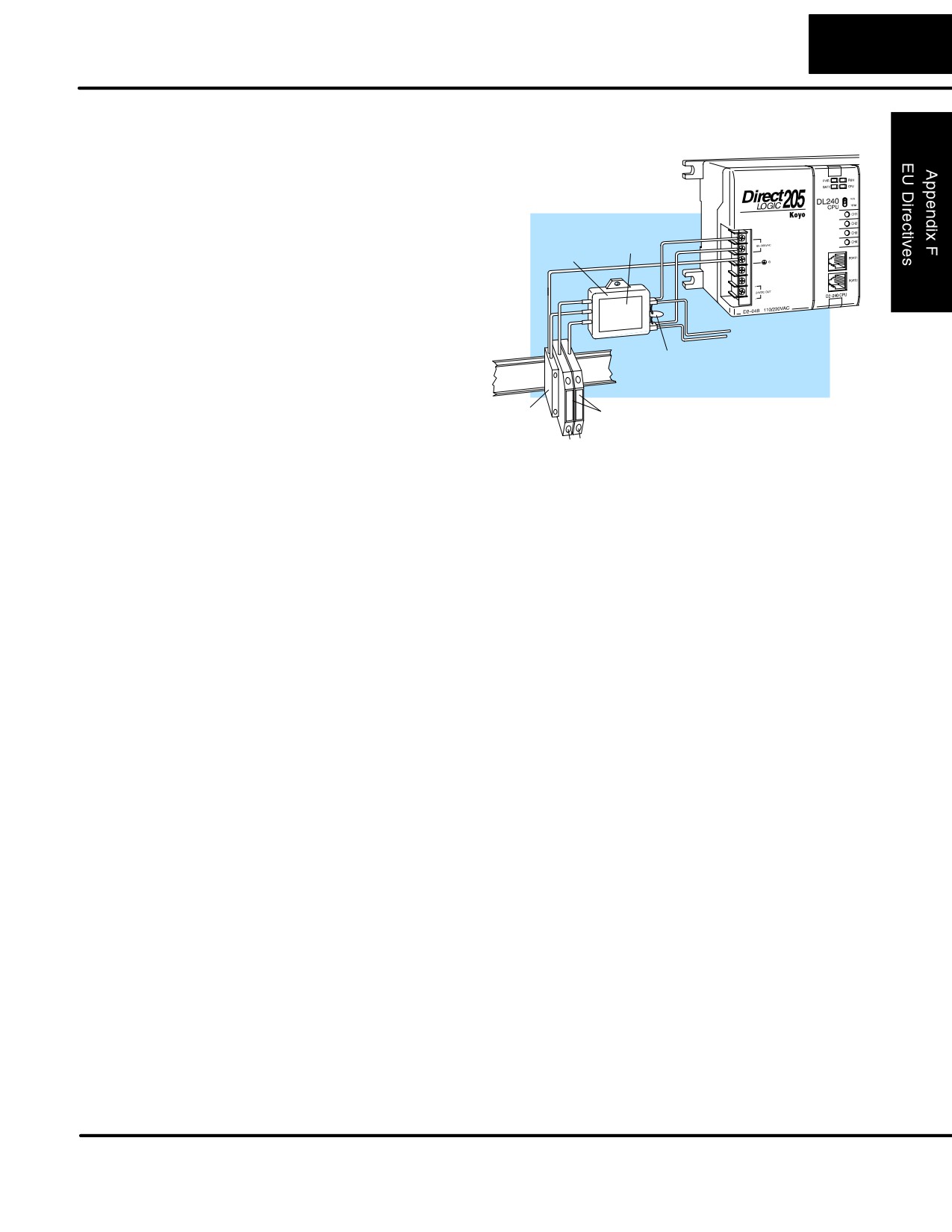
DL105, DL205 and DL305 AC
powered base power supplies
require extra mains filtering to
comply with the EMC Directive
on conducted RF emissions.
All PLC equipment has been
Schaffner
FN2010
tested with filters from
Filter
Schaffner, which reduce
emissions to negligible levels if
the filters
are properly
grounded
(earth ground). A
To AC
filter with a current rating
Input
suitable to supply all PLC
Transient
Circuitry
Suppressor
power supplies and AC input
modules should be selected.
Fused
We suggest the FN2010 for
Earth
Terminals
DL105/DL205 systems and
Terminal
the FN2080 for DL305
L N
systems. DL405 systems do
not require extra filtering.
Suppression and
In order to comply with the fire risk requirements of the Low Voltage and Machinery
Fusing
Directive electrical standards EN 61010-1, and EN 60204-1, by limiting the power
into “unlimited” mains circuits with power leads reversed, it is necessary to fuse both
AC and DC supply inputs. You should also install a transient voltage suppressor
across the power input connections of the PLC. Choose a suppressor such as a metal
oxide varistor, with a rating of 275VAC working voltage for 230V nominal supplies
(150VAC working voltage for 115V supplies) and high energy capacity (eg. 140
joules).
Transient suppressors must be protected by fuses and the capacity of the transient
suppressor must be greater than the blow characteristics of the fuses or circuit
breakers to avoid a fire risk. A recommended AC supply input arrangement for Koyo
PLCs is to use twin 3 amp TT fused terminals with fuse blown indication, such as
DINnectors DN-F10L terminals, or twin circuit breakers, wired to a Schaffner FN2010
filter or equivalent, with high energy transient suppressor soldered directly across the
output terminals of the filter. PLC system inputs should also be protected from voltage
impulses by deriving their power from the same fused, filtered, and surge-suppressed
supply.
Internal Enclosure
A heavy-duty star earth terminal block should be provided in every cubicle for the
Grounding
connection of all earth ground straps, protective earth ground connections, mains
filter earth ground wires, and mechanical assembly earth ground connections. This
should be installed to comply with safety and EMC requirements, local standards, and
the requirements found in IEC 1000-5-2.The Machinery Directive also requires that
the common terminals of PLC input modules, and common supply side of loads driven
from PLC output modules should be connected to the protective earth ground
terminal.
DL105 PLC User Manual, 2nd Edition, Rev. A
F-6
European Union Directives
Equi-potential
Grounding
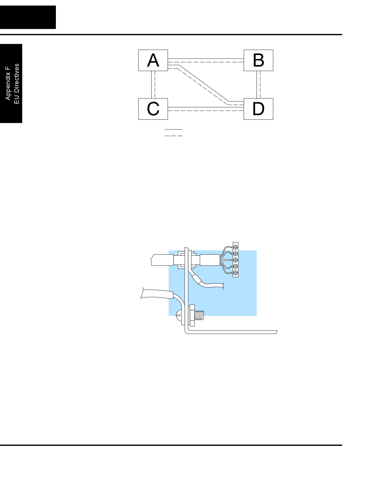
Serial Communication Cable
Key
Equi-potential Bond
Adequate site earth grounding must be provided for equipment containing modern
electronic circuitry. The use of isolated earth electrodes for electronic systems is
forbidden in some countries. Make sure you check any requirements for your
particular destination. IEC 1000-5-2 covers equi-potential bonding of earth grids
adequately, but special attention should be given to apparatus and control cubicles
that contain I/O devices, remote I/O racks, or have inter-system communications with
the primary PLC system enclosure. An equi-potential bond wire must be provided
alongside all serial communications cables, and to any separate items of the plant
which contain I/O devices connected to the PLC. The diagram shows an example
of four physical locations connected by a communications cable.
Conductive
Communications
Screened
Adapter
and Shielded
Cable
Cables
Serial
ÎÎÎÎ
I/O
ÎÎÎÎ
To Earth
Block
Equi-potential
Bond
Control Cubicle
Good quality 24 AWG minimum twisted-pair shielded cables, with overall foil and
braid shields are recommended for analog cabling and communications cabling
outside of the PLC enclosure. To date it has been a common practice to only provide
an earth ground for one end of the cable shield in order to minimize the risk of noise
caused by earth ground loop currents between apparatus. The procedure of only
grounding one end, which primarily originated as a result of trying to reduce hum in
audio systems, is no longer applicable to the complex industrial environment.
Shielded cables are also efficient emitters of RF noise from the PLC system, and can
interact in a parasitic manner in networks and between multiple sources of
interference.
DL105 PLC User Manual, 2nd Edition, Rev. A
F-7
European Union Directives
The recommendation is to use shielded cables as electrostatic “pipes” between
apparatus and systems, and to run heavy gauge equi-potential bond wires
alongside all shielded cables. When a shielded cable runs through the metallic wall
of an enclosure or machine, it is recommended in IEC 1000-5-2 that the shield
should be connected over its full perimeter to the wall, preferably using a conducting
adapter, and not via a pigtail wire connection to an earth ground bolt. Shields must be
connected to every enclosure wall or machine cover that they pass through.
Analog and RS232
Providing an earth ground for both ends of the shield for analog circuits provides the
Cables
perfect electrical environment for the twisted pair cable as the loop consists of signal
and return, in a perfectly balanced circuit arrangement, with connection to the
common of the input circuitry made at the module terminals. RS232 cables are
handled in the same way.
Multidrop Cables
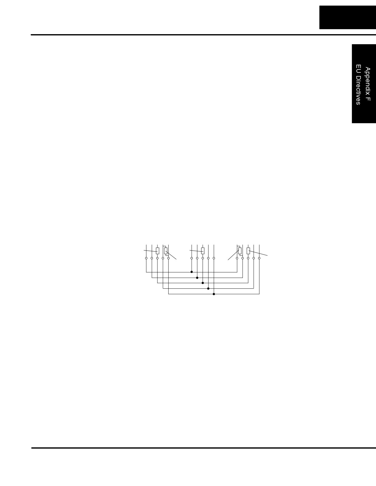
RS422 twin twisted pair, and RS485 single twisted pair cables also require a 0V link,
which has often been provided in the past by the cable shield. It is now
recommended that you use triple twisted pair cabling for RS422 links, and twin
twisted pair cable for RS485 links. This is because the extra pair can be used as the
0V inter-system link. With loop DC power supplies earth grounded in both systems,
earth loops are created in this manner via the inter-system 0v link. The installation
guides encourage earth loops, which are maintained at a low impedance by using
heavy equi-potential bond wires. To account for non-European installations
using single-end earth grounds, and sites with far from ideal earth ground
characteristics, we recommend the addition of 100 ohm resistors at each 0V
link connection in network and communications cables.
Last Slave
Slave n
Master
TXD 0V
RXD
TXD 0V RXD
RXD 0V TXD
+
-
+
-
+
-
+
-
+
-
+
-
100W
100W
100W
Termination
Termination
When you run cables between PLC items within an enclosure which also contains
Shielded Cables
susceptible electronic equipment from other manufacturers, remember that these cables
within Enclosures
may be a source of RF emissions. There are ways to minimize this risk. Standard data
cables connecting PLCs and/or operator interfaces should be routed well away from other
equipment and their associated cabling. You can make special serial cables where the
cable shield is connected to the enclosure’s earth ground at both ends, the same way as
external cables are connected.
Network Isolation For safety reasons, it is a specific requirement of the Machinery Directive that a keyswitch
must be provided that isolates any network input signal during maintenance, so that
remote commands cannot be received that could result in the operation of the machinery.
The FA-ISONET does not have a keyswitch! Use a keylock and switch on your enclosure
which when open removes power from the FA-ISONET. To avoid the introduction of
noise into the system, any keyswitch assembly should be housed in its own earth
grounded steel box and the integrity of the shielded cable must be maintained.
Again, for further information on EU directives we recommend that you get a copy of
our EU Installation Manual (DA-EU-M). Also, if you are connected to the World
Wide Web, you can check the EU Commision’s official site at:
DL105 PLC User Manual, 2nd Edition, Rev. A