Indian motorcycle 2017. Service Manual - page 38
10.68
9927618 R03 - 2017 Indian Motorcycle (Full-Size) Service Manual
IINNSSTTRRUUM
MEENNTT CCLLUUSSTTEERR ((CCHHIIEEFFTTAAIINN // RROOAADDM
MAASSTTEERR))
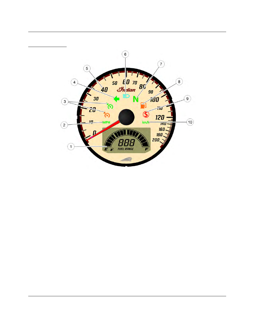
SPEEDOMETER DISPLAY
|
|
|
10.68 9927618 R03 - 2017 Indian Motorcycle (Full-Size) Service Manual IINNSSTTRRUUM MEENNTT CCLLUUSSTTEERR ((CCHHIIEEFFTTAAIINN // RROOAADDM MAASSTTEERR)) SPEEDOMETER DISPLAY |