Indian motorcycle 2017. Service Manual - page 36


  Главная      Manuals     Indian motorcycle 2017. Service Manual


Search            copyright infringement  


Content      ..     34      35      36      37     ..


Indian motorcycle 2017. Service Manual - page 36


10.36

9927618 R03 - 2017 Indian Motorcycle (Full-Size) Service Manual

EECCM

M CCOONNNNEECCTTOORR M

MAAPP

See ECM Connector Map, page 4.24.

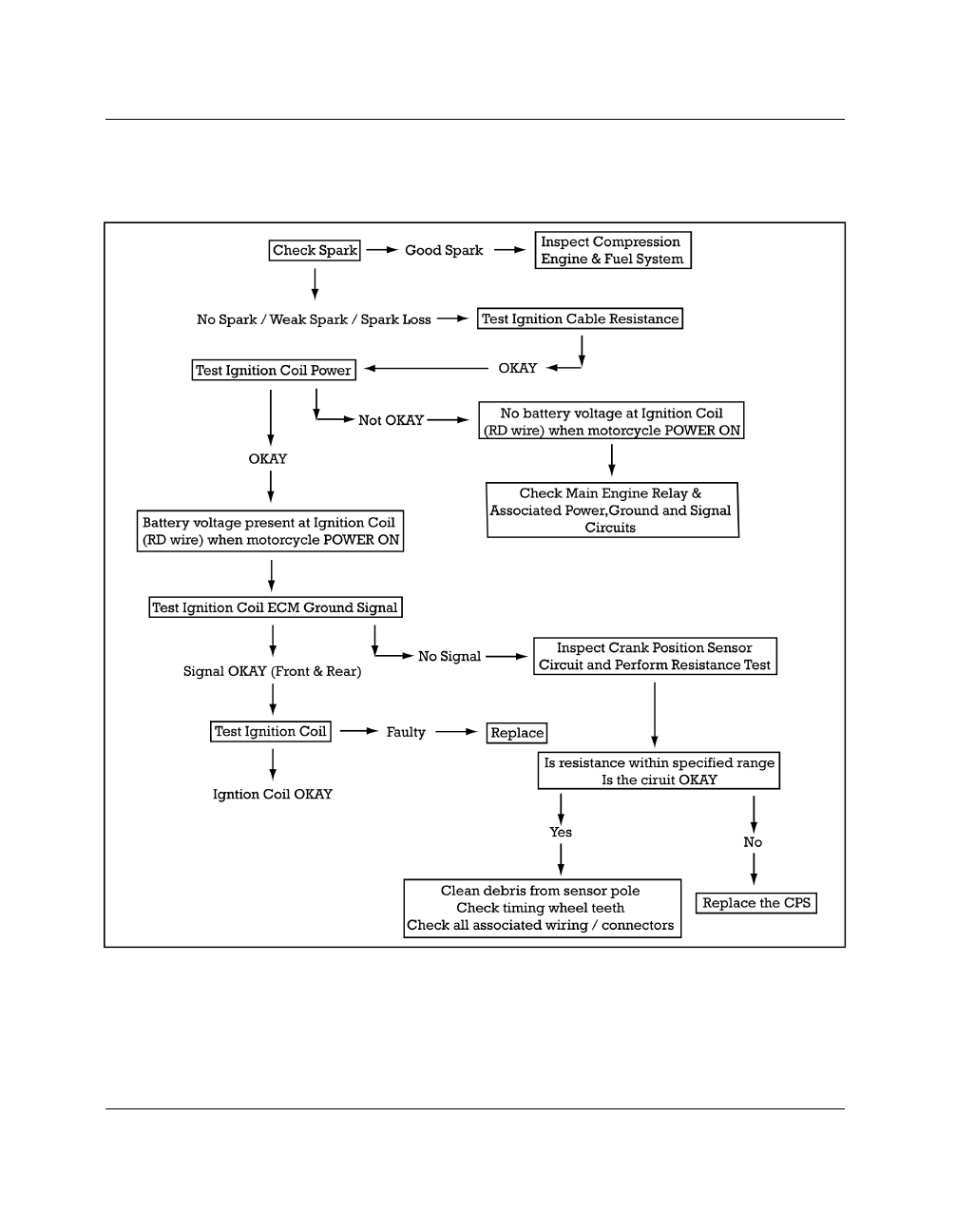
IIGGNNIITTIIOONN SSYYSSTTEEM

M TTEESSTT FFLLOOW

WCCHHAARRTT

ELECTRICAL

10

10.37

BBAATTTTEERRYY VVOOLLTTAAGGEE IINNSSPPEECCTTIIOONN:: TTEESSTT 11

1.

Remove the seat. See Seat Removal / Installation -
All (except Roadmaster), page 7.21.

2.

Set multi meter to measure DC Volts.

3.

Inspect battery voltage.

4.

If the battery voltage is below 12.5 V DC charge or
replace the battery with a fully charged battery.

NOTE

When operating the starter with a low battery, the

voltage available for the ignition coils can drop

below the minimum required to produce spark.

SSPPAARRKK IINNSSPPEECCTTIIOONN:: TTEESSTT 22

1.

Connect an inductive timing light to one spark
plug wire.

2.

Press ON to power up the motorcycle and place
the STOP/RUN switch in the RUN position.

3.

Shift transmission into neutral and pull in clutch
lever.

4.

Depress starter button and observe timing light.

5.

Determine

if

timing

light

flashes

without

interruption for both cylinders.

6.

Consistent flashes indicate that some secondary
voltage is present. The likelihood of an ignition
related problem is reduced but not eliminated.
Keep the following points in mind:

• There is a threshold voltage and amperage

requirement for timing lights below which they will
not trigger and therefore, not flash.

• Fouled spark plugs may drop secondary voltage so

low that a timing light will not trigger and therefore,
not flash.

• With no current flowing (open secondary side of the

ignition coil) the timing light will not flash.

• A faulty high tension lead (plug wire) or poor

connection is one example of an open secondary.

7.

Replace spark plugs, connect plug wires and re-
test.

8.

If timing light does not flash consistently for one or
both cylinders, test high tension leads (Test 3).

IIGGNNIITTIIOONN CCAABBLLEE RREESSIISSTTAANNCCEE:: TTEESSTT 33

1.

Remove high tension leads by pulling firmly on the
boots at the coil and spark plug. DO NOT pull on
the wire or it may become permanently damaged.

NOTE

The plug caps or coil ends are NOT removable. Wire

must be replaced as an assembly.

2.

Test each high tension lead with an ohmmeter and
compare to specification. Move wire to detect
internal breaks or poor connections at terminal
ends.

High Tension Lead Resistance: 1860

Ω

± 20%

ELECTRICAL

10.38

9927618 R03 - 2017 Indian Motorcycle (Full-Size) Service Manual

IIGGNNIITTIIOONN CCOOIILL PPOOW

WEERR &

& GGRROOUUNNDD SSIIGGNNAALL TTEESSTT 44

Power To Ignition Coil

Battery voltage must be present at the ignition coil (Pin
B) when the power button is switched on and the
electrical system powered up.

1.

Disconnect the electrical connector from the
ignition

coil.

See

Ignition

Coil

Removal

/

Installation, page 10.40.

2.

Set the multi meter to measure VDC and insert the
meter leads into the appropriate jacks.

3.

Connect the black lead to ground (on the engine).

4.

Connect a small thin test adapter lead to the
center terminal of the ignition coil primary
connector and the red meter lead to the test
adapter.

5.

Press

the

power

button

to

power

up

the

motorcycle electrical system and place the STOP/
RUN switch in the RUN position.

6.

Battery voltage should appear on the center
terminal of the coil connector (RD wire).

7.

With transmission in Neutral, crank the engine.
Battery voltage should again be present on center
wire.

Ignition Coil Ground Signal

The following steps will test the ECM (Ground)
Signal To Ignition Coil

ECM ground signal must be present at each of the
outer terminals of the ignition coil primary
harness connector. The signal will appear as a
pulse on the meter between Ground (-) and Open
(OL).

8.

Set the multi meter to measure resistance (

Ω

).

9.

Place a small thin test adapter into one of the outer
terminals of the ignition coil connector (either the
WH or BK wire) and connect one meter lead to the
test adapter..

10. Ground the other lead to the engine.

11. Place transmission in Neutral.

12. Press

the

power

button

to

power

up

the

motorcycle electrical system and place the STOP/
RUN switch in the RUN position.

13. Crank the engine with the electric starter and

watch the display on the multi meter. The meter
display should pulse evenly while engine is
cranking, indicating a ground signal is present.

14. Repeat the test on the other outside wire in the

connector.

• If no pulse is present, test the Crankshaft Position

Sensor.

• If the signal is present on one wire and not the other,

test related wiring and connections.

• If both signals are present and there was battery

voltage on the RD wire (center terminal) but still no
spark, test the ignition coil windings. (Test 5).

ELECTRICAL

10

10.39

IIGGNNIITTIIOONN CCOOIILL RREESSIISSTTAANNCCEE:: TTEESSTT 55

Ignition Coil Primary Winding

1.

Remove ignition coil. See

2.

Set the multi meter to measure resistance (

Ω

) and

insert the meter leads into the appropriate jacks.

3.

Measure

resistance

between

terminal

3

and

terminal 2 on the coil. Compare to specification.

4.

Measure

resistance

between

terminal

1

and

terminal 2 on the coil. Compare to specification.

Primary Coil Resistance: 0.4–0.6

Ω

Ignition Coil Secondary Windings

5.

Remove ignition coil. See Ignition Coil Removal /
Installation, page 10.40.

6.

Select DIODE CHECK function on the multi meter.

7.

Place red meter lead on terminal 2 (center) of coil
primary and black lead on secondary terminal
and record.

8.

Move black DMM lead to the other secondary
terminal and record. (Reading should be the same
for both secondary windings).

9.

Repeat measurements on each secondary coil with
meter leads reversed.

NOTE

Diode inside the secondary coil requires the Diode

Check function of multi meter.

Secondary Coil Resistance: 2.0–2.5 VDC

or

Open Line (OL) with leads reversed

10. Compare readings to specification. Resistance

should be low with leads one way and OL with
leads reversed.

CCRRAANNKKSSHHAAFFTT PPOOSSIITTIIOONN SSEENNSSOORR ((CCPPSS)) RREESSIISSTT--

AANNCCEE IINNSSPPEECCTTIIOONN::

See Crankshaft Position Sensor, Test / Replace, page
4.50.

ELECTRICAL

10.40

9927618 R03 - 2017 Indian Motorcycle (Full-Size) Service Manual

IIGGNNIITTIIOONN CCOOIILL RREEM

MOOVVAALL // IINNSSTTAALLLLAATTIIOONN

1.

Verify that motorcycle is not powered up and the
STOP / RUN switch is in the OFF position.

2.

Remove the horn assembly. See Horn Removal /
Installation, page 10.56.

3.

Remove the ignition cables from the coil and
disconnect the electrical connector from the coil.

4.

Remove the ground wire

q

from the coil bracket.

5.

Release harness retainer from coil bracket.

6.

Using a 10mm socket, remove the four fasteners

w

securing the coil bracket to the engine and
remove the coil assembly.

7.

INSTALLATION

of

the

ignition

coil

is

performed

by

reversing

the

removal

procedure. Torque fasteners to specification.

TORQUE

Coil Ground to Bracket:

84 in-lbs (10 Nm)

Ignition Coil to Bracket:

84 in-lbs (10 Nm)

ELECTRICAL

10

10.41

CCHHAASSSSIISS EELLEECCTTRRIICCAALL

GGEENNEERRAALL IINNFFOORRM

MAATTIIOONN

SSEERRVVIICCEE NNOOTTEESS

Keep the following notes in mind when diagnosing an
electrical problem:

• Refer to wiring diagram for stator and electrical

component resistance specifications.

• When measuring resistance of a component that has

a resistance value under 10 Ohms, remember to
subtract meter lead resistance from the reading.
Connect the leads together and record the
resistance. The resistance of the component is equal
to tested value minus the lead resistance.

• Become familiar with the operation of your meter. Be

sure leads are in the proper jack for the test being
performed (i.e. 10A jack for current readings). Refer
to the Owner’s Manual included with your meter for
more information.

• Pay attention to the prefix on the multimeter reading

(K, M, etc.) and the position of the decimal point.

• For resistance readings, isolate the component to be

tested. Disconnect it from the wiring harness or
power supply.

SSPPEECCIIAALL TTOOOOLLSS

TOOL DESCRIPTION

PART NUMBER

Battery Tester

PV-50296

Electrical Tester Kit

PV-43526

Smartlink Module Kit

PU-47471

TPMS Activation Tool

PF-51288

USB to Serial Adapter

PU-50621

TTOORRQQUUEE SSPPEECCIIFFIICCAATTIIOONNSS

PART DESCRIPTION

TORQUE

SPECIFICATION

Head Light Bezel
(Chieftain / Roadmaster)

36 in-lbs (4 Nm)

Head Light Retaining
Ring

12 in-lbs (1 Nm)

Horn to Bracket Nut

84 in-lbs (10 Nm)

Ignition Cover

84 in-lbs (10 Nm)

License Plate Bracket to
Tail Light

84 in-lbs (10 Nm)

License Plate Light

15 in-lbs (2 Nm)

Tail Light Fastener

84 in-lbs (10 Nm)

Turn Signal Fastener

18 ft-lbs (24 Nm)

Turn Signal, Front
(Chieftain / Roadmaster)

36 in-lbs (4 Nm)

VCM Mounting Plate

84 in-lbs (10 Nm)

ELECTRICAL

10.42

9927618 R03 - 2017 Indian Motorcycle (Full-Size) Service Manual

AASSSSEEM

MBBLLYY VVIIEEW

WSS

HHEEAADD LLIIGGHHTT

NUMBER

PART DESCRIPTION

TORQUE (IF APPLICABLE)

q

Fastener, Retaining Ring (QTY.4)

12 in-lbs (1 Nm)

w

Retaining Ring

-

e

Head Light Housing

-

r

Fastener, Head Light Mount

NA

t

Fastener, Adjuster

NA

y

Spring, Adjuster

-

u

Head Light Carrier

-

ELECTRICAL

10

10.43

TTAAIILL LLIIGGHHTT // LLIICCEENNSSEE PPLLAATTEE LLIIGGHHTT

NUMBER

PART DESCRIPTION

TORQUE (IF APPLICABLE)

q

Fastener, Turn Signal — M8 x 1.25 x 12 (QTY.2)

18 ft-lbs (24 Nm)

w

Fastener, Tail Light Asm — M6 x 1.0 x 10
(QTY.3)

84 in-lbs (10 Nm)

e

Pad, Tail Light Bezel

-

ELECTRICAL

10.44

9927618 R03 - 2017 Indian Motorcycle (Full-Size) Service Manual

FFUUSSEE BBOOXX

FFUUSSEE BBOOXX LLOOCCAATTIIOONN

There are two fuse boxes utilized on the full size Indian
Motorcycle platform.

• The J-Case fuse box

q

which is located on the rear

of the battery box.

• The main fuse box

w

which is located beneath the

LH upper side cover.

ELECTRICAL

10

10.45

FFUUSSEE AAPPPPLLIICCAATTIIOONN CCHHAARRTT

PIN

CIRCUIT DESCRIPTION

FROM

TO

1

Engine Breaker Output

Fuse Box

Splice (ENGBRK)

2

Engine Relay Power Output

Fuse Box

Splice (ENGPWR)

3

Engine Relay Power Output

Fuse Box

Splice (ENGPWR)

4

Fuel Pump Power

Fuse Box

Fuel Pump

5

Engine Breaker Output

Fuse Box

Splice (ENGBRK)

6

Main Engine Relay Control

Fuse Box

Splice (E115)

7

Run / Stop Switch Power

Fuse Box

Splice (ENGBRK)

8

Fuel Pump Relay Control

ECM 1

Fuse Box

9

Engine Relay Power Output

Fuse Box

Splice (ENGPWR)

10

Starter Solenoid Control

Fuse Box

Starter Solenoid

11

Chassis Fuse Power Output

Fuse Box

Splice (CHPWR)

12

Auxiliary Engine Relay Power Output

Fuse Box

Splice (AUXENG)

13

Engine Relay Power Output

Splice (ENGPWR)

Fuse Box

14

Starter Relay Control

ECM 1

Fuse Box

15

Chassis Fuse Power Output

Fuse Box

Splice (CHPWR)

16

Main Engine Relay Control

Fuse Box

Splice (E115)

17

Auxiliary Engine Relay Power Output

Fuse Box

Splice (AUXENG)

ELECTRICAL

10.46

9927618 R03 - 2017 Indian Motorcycle (Full-Size) Service Manual

PIN

CIRCUIT DESCRIPTION

FROM

TO

18

Accessory Switched Output

Fuse Box

Splice (ACCSW)

19

Switched Power Control

VCM A

Fuse Box

20

Switched Power

Fuse Box

Fuse Box

21

Auxiliary Switched Fuse Output

Fuse Box

Fuse Box

22

Auxiliary Switched Relay Control

ECM 1

Fuse Box

23

VCM Accessory Power Output

Fuse Box

Splice (VCMACC)

24

Ground

Splice (GND2)

Fuse Box

25

Main Fuse Output

Splice (MPWR)

Fuse Box

26

Not Used

27

Not Used

28

Not Used

29

VCM Power Control

VCM B

Fuse Box

30

Not Used

31

Not Used

32

Not Used

33

Main Fuse Output

Fuse Box

Splice (MPWR)

34

Main Fuse Output

Fuse Box

Splice (MPWR)

35

Main Fuse Output

Fuse Box

Splice (MPWR)

36

Main Fuse Output

Fuse Box

Splice (MPWR)

37

Engine Breaker Output

Fuse Box

Splice (ENGBRK)

38

Chassis Fuse Output Power

Fuse Box

Splice (CHPWR)

39

Switched Power

Fuse Box

Fuse Box

40

Radio Fuse Output Power

Fuse Box

Fairing

41

Main Fuse Output

Splice (MPWR)

Fuse Box

42

Main Fuse Output

Splice (MPWR)

Fuse Box

43

Main Fuse Output

Fuse Box

Splice (MPWR)

44

Main Fuse Output

Fuse Box

Splice (MPWR)

45

Accessory Constant Fuse Output

Fuse Box

Splice (ACCCONST1)

46

Auxiliary Switched Fuse Output

Fuse Box

Fuse Box

47

Instrumentation Fuse Output

Fuse Box

Speedometer

48

Trunk Amp Power

Fuse Box

Trunk

ELECTRICAL

10

10.47

VVEEHHIICCLLEE CCOONNTTRROOLL M

MOODDUULLEE ((VVCCM

M))

VVEEHHIICCLLEE CCOONNTTRROOLL M

MOODDUULLEE ((VVCCM

M)) SSEERRVVIICCEE NNOOTTEESS

Replacement of the Vehicle Control Module (VCM)
should only be performed by a qualified dealer.
Vehicle

Control

Module

(VCM)

setup

and

initialization requires the use of Digital Wrench.

ELECTRICAL

10.48

9927618 R03 - 2017 Indian Motorcycle (Full-Size) Service Manual

VVEEHHIICCLLEE CCOONNTTRROOLL M

MOODDUULLEE ((VVCCM

M)),,

RREEM

MOOVVAALL // IINNSSTTAALLLLAATTIIOONN

CAUTION

The negative battery cable MUST be disconnected

before the VCM can be removed.

Electrical tape can be used to cover the negative

battery terminal and cable end to prevent a short

from occurring across the VCM during removal.

1. Connect to vehicle using Digital Wrench.

2. Using Digital Wrench, access and record the Key

Fob number.

3. Record the 4 digit consumer PIN (as provided by

the consumer).

4. Remove seat. See Seat Removal / Installation - All

(except Roadmaster), page 7.21.

5. Using a 5mm hex wrench, remove the bolt

w

securing the VCM mounting plate to the battery
box.

6. Disconnect the negative battery cable.

7. Disconnect the three multi-plugs

q

from the VCM.

8. Lift the VCM / mounting plate assembly from the

rear and disengage hinge pins from the battery
box to remove.

9.

INSTALLATION is performed by reversing the
removal procedure.

10. Torque

the

VCM

mounting

fastener

to

specification.

TORQUE

Vehicle Control Module Mounting Plate Fastener:

84

in-lbs (10 Nm)

11. Reconnect to vehicle using Digital Wrench.

12. Using Digital Wrench, program the Key Fob

number.

13. Set a new consumer PIN.

14. Record the new Master PIN by uploading a new

Service Report.

15.

Chieftain

/

Roadmaster

ONLY:

Initialize

/

reactivate the TPMS sensors.

16. Test ride the vehicle to verify all systems are

operating correctly.

ELECTRICAL

10

10.49

VVCCM

M CCOONNNNEECCTTOORR M

MAAPP

Connector: VCM A

PIN NUMBER

WIRE COLOR

FUNCTION

1

YE/WH

START SWITCH OUTPUT

2

BU/WH

BAG UNLOCK

3

BU/DG

BAG LOCK

4

VT/YE

IGNITION SWITCH SIGNAL

5

WH

NOT USED

6

-

-

7

WH

NOT USED

8

YE

CAN HIGH

9

DG

CAN LOW

10

PK

NOT USED

11

OG/YE

SWITCHED POWER CONTROL

12

GY/RD

AUX LIGHT SWITCH INDICATOR LIGHT

13

BU/RD

HEATED GRIP SWITCH OUTPUT

14

-

-

15

-

-

16

-

-

17

YE/BK

TRANS GEAR POSITION SENSOR OUTPUT

18

BK

NOT USED

ELECTRICAL

10.50

9927618 R03 - 2017 Indian Motorcycle (Full-Size) Service Manual

Connector: VCM 1

PIN NUMBER

WIRE COLOR

FUNCTION

1

YE

HIGH BEAM OUTPUT

2

DG

LOW BEAM OUTPUT

3

PK

HEATED GRIPS OUTPUT

4

WH

HORN POWER

5

RD

VCM POWER

6

GY/DB

WINDSHIELD MOTOR A

7

GY/DG

WINDSHIELD MOTOR B

8

OG/WH

LOCK B SIGNAL

9

RD/WH

LOCK A SIGNAL

10

-

-

11

RD

VCM POWER

12

DG/RD

LH AUX LIGHT POWER

13

DG/BN

RH AUX LIGHT POWER

14

BN/WH

NOT USED

15

-

-

16

-

-

17

BK

VCM GROUND

18

-

-

19

-

-

20

RD

VCM POWER

ELECTRICAL

10

10.51

Connector: VCM B

PIN NUMBER

WIRE COLOR

FUNCTION

1

RD/YE

VCM CONTOL POWER

2

WH/BK

MODE SWITCH 1

3

GN

MODE SWITCH 2

4

GY

HORN SWITCH OUTPUT

5

DG/YE

HEADLIGHT CONTROL

6

DG/BK

AUX LIGHT SWITCH OUTPUT

7

DB/BK

HAZARD SWITCH OUTPUT

8

YE/BD

OIL PRESSURE SWITCH

9

BK

NOT USED

10

OG

CRUISE CONTROL ON/OFF SWITCH OUTPUT

11

WH

CRUISE CONTROL SET/ACCEL SWITCH

12

WH/DG

CRUISE CONTROL RESUME / DECEL SWITCH

13

BU/YE

HEATED GRIP SWITCH INCREASE

14

BU/BK

HEATED GRIP SWITCH DECREASE

15

YE/DG

LEFT TURN SIGNAL CONTROL

16

BN

RIGHT TURN SIGNAL CONTROL

17

BN/DB

WINDSHIELD SWITCH UP

18

DG/DB

WINDSHIELD SWITCH DOWN

ELECTRICAL


Content      ..     34      35      36      37     ..