Indian motorcycle 2017. Service Manual - page 37


  Главная      Manuals     Indian motorcycle 2017. Service Manual


Search            copyright infringement  


Content      ..     35      36      37      38     ..


Indian motorcycle 2017. Service Manual - page 37


10.52

9927618 R03 - 2017 Indian Motorcycle (Full-Size) Service Manual

HHEEAADDLLIIGGHHTT SSEERRVVIICCEE

HHEEAADDLLIIGGHHTT BBUULLBB RREEPPLLAACCEEM

MEENNTT -- AALLLL M

MOODDEELLSS

IMPORTANT

Avoid touching a halogen bulb with bare fingers. Oil

from your skin leaves a residue, causing a hot spot

that will shorten the life of the bulb. If a bulb is

touched, clean it thoroughly with denatured alcohol.

Chief Classic / Chief Vintage / Chief Dark Horse /
Springfield

NOTE

It is not necessary to remove the headlight nacelle to
replace the headlight bulb on

Chief Classic / Chief

Vintage / Chief Dark Horse / Springfield

models.

1. Turn handlebar all the way to the left.

2. Reach in the space between the head tube and

nacelle to remove bulb and disconnect.

3. Using a clean, oil-free cloth, replace the headlight

bulb.

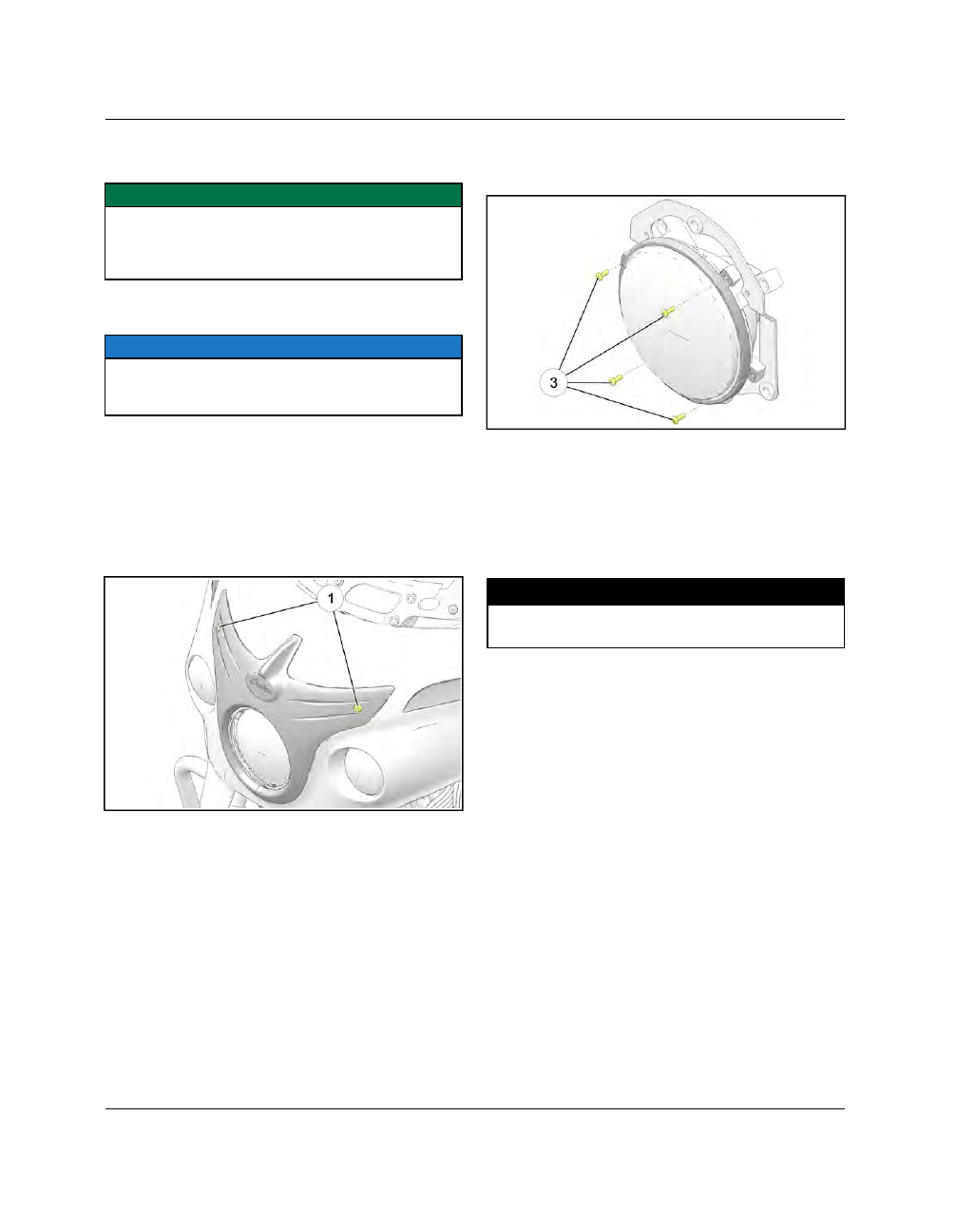
Chieftain Dark Horse / Chieftain / Roadmaster

1. Remove two fasteners

q

and head light bezel.

2. Remove fasteners

e

. Remove headlight retaining

ring and withdraw the reflector assembly far
enough to remove bulb.

3. Remove the headlight bulb from the reflector and

unplug.

4. Using a clean, oil-free cloth, install the new

headlight bulb.

5.

Reverse removal procedure to install.

6. Torque

all

fasteners

to

specification

upon

reassembly.

TORQUE

Headlight Retaining Ring Fasteners:

12 in-lbs (1 Nm)

Bezel Fasteners:

36 in-lbs (4 Nm)

ELECTRICAL

10

10.53

HHEEAADDLLIIGGHHTT W

WAARRNNIINNGG IINNDDIICCAATTOORRSS

Indian motorcycles are equipped with “tell tales”
indicating when a fault occurs with the low or high
beam headlight.

2014 models:

If a fault occurs with the headlight bulb

(low or high beam) the ‘Check Engine’ light will
illuminate and fault codes will be stored. Once the
bulb has been replaced and the issue corrected, the
‘Check Engine’ light will turn off however stored fault
codes will need to be erased.

2015 and later models:

If a fault occurs with the

headlight bulb (low or high beam) the high beam
indicator light will flash on the instrument cluster.
Once the bulb has been replaced and the issue
corrected, the high beam indicator will return to
normal operation.

ELECTRICAL

10.54

9927618 R03 - 2017 Indian Motorcycle (Full-Size) Service Manual

HHOORRNN SSEERRVVIICCEE

GGEENNEERRAALL OOVVEERRIIEEW

W

The horn uses a load-sensing circuit for diagnostic
purposes. The VCM sends a 12V pull-up voltage to the
horn through the WH wire.

• With the horn disconnected, you should see 12V at

the horn connector when checked with a DVOM.

• When the horn is connected, the 12V pull-up goes

away.

• The horn circuit is a Normally Open circuit, so

depressing the horn provides the VCM a path to
ground. The VCM responds by sending 12V to the
horn making it sound.

LLOOAADD SSIIDDEE TTEESSTTIINNGG

12 VDC is supplied to the WH wire.

• With the horn disconnected, Use a DVOM to probe

the WH wire at the connector and chassis ground.
Voltage reading should be 12V.

• Connect the horn and probe the WH wire at the

connector and chassis ground. Voltage reading
should be 0V.

• Resistance from the horn connector BK to GND

should be 0.2 Ohms.

• Resistance from the WH wire to the VCM should be

0.2 Ohms.

• With the horn connected, probe the BK and WH

wires. Depress the horn. Voltage reading should be
12V.

SSW

WIITTCCHH SSIIDDEE TTEESSTTIINNGG

8 VDC is supplied on the Gray wire to the horn button.

• Voltage should read 0.005 when the button is

depressed.

• Digital Wrench can see button switch open and

close.

• With the VCM connected, bypass the switch by

providing the the GY wire a direct path to ground.
The horn should sound until the ground path is
removed.

ELECTRICAL

10

10.55

HHOORRNN BBRREEAAKKOOUUTT DDIIAAGGRRAAM

M

ELECTRICAL

10.56

9927618 R03 - 2017 Indian Motorcycle (Full-Size) Service Manual

HHOORRNN RREEM

MOOVVAALL // IINNSSTTAALLLLAATTIIOONN

1.

Remove the three fasteners

q

securing the horn

cover to the bracket and remove cover.

2.

Disconnect the horn electrical connector

w

.

3.

Using a 10mm wrench, remove the fastener

e

securing the horn to the ignition coil bracket.
Remove the horn.

4.

Installation is performed by reversing the
removal procedure.

5.

Torque fasteners to specification.

TORQUE

Horn to Bracket:

84 in-lbs (10 Nm)

TORQUE

Ignition Coil Cover:

84 in-lbs (10 Nm)

ELECTRICAL

10

10.57

TTAAIILL LLIIGGHHTT SSEERRVVIICCEE

LLEEDD TTAAIILL // BBRRAAKKEE LLIIGGHHTT OOPPEERRAATTIIOONN

The multiple LED tail / brake lamp functions much like
a conventional incandescent tail / brake lamp. LED
lights require a regulated current supply to prevent
damage, so a current regulation circuit is incorporated
inside the tail lamp unit. Direct 12 volt battery power
can be applied directly to the brake or tail lamp wire
for testing purposes, but polarity MUST be observed
or the LEDs will be permanently damaged.

Tail / Brake Light Power Supply:

When the motorcycle is powered ON, battery voltage
is delivered to the TAIL / BRAKE LEDs on the DARK
BLUE / PINK wire from the Secondary Engine Relay.
Current through each TAIL LED (WHITE wire) is
limited (inside tail lamp unit) to approximately 250
mA.

Tail / Brake Light Ground Signal:

The front and rear brake light switches provide a path
to ground to the ECM via WHITE / RED wire (front
brake switch) and YELLOW / VIOLET wire (rear brake
switch). When the ECM receives a grounding signal
from either of the brake switches, ground is provided
to the tail / brake light LED, thus illuminating the light.

When the motorcycle is powered ON, the ECM
provides a ground path to the tail light LED, thus
illuminating the light.

TTAAIILL // BBRRAAKKEE // LLIICCEENNSSEE PPLLAATTEE LLIIGGHHTT,, RREEM

MOOVVAALL //

IINNSSTTAALLLLAATTIIOONN

NOTE

The tail and brake lights are LEDs and cannot be

replaced individually. If the lights fail to function

when activated, and all circuit tests indicate correct

power and ground distribution, the tail /brake light

must be replaced as an assembly. The license plate

light can be replaced individually.

1.

Place the motorcycle in an upright position with
the front wheel clamped in a wheel vise.

2.

Working from beneath the rear fender, access the
three tail light fasteners

q

and remove.

3.

Lift the tail light assembly off of the rear fender
and disconnect the electrical connectors

w

noting

their position for reassembly.

4.

Remove the tail light assembly.

License Plate Light Removal

ELECTRICAL

10.58

9927618 R03 - 2017 Indian Motorcycle (Full-Size) Service Manual

5.

Remove nuts

e

and washers.

6.

Remove the two fasteners

r

and separate the

license plate bracket from the tail light assembly.

7.

Remove the license plate light

t

from the license

plate bracket.

Tail / Brake Light Removal

8.

Remove fastener

y

and remove the tail light from

the mount.

9.

Installation is performed by reversing the
removal procedure. Torque all fasteners to
specification.

TORQUE

Tail Light to Mount:

84 in-lbs (10 Nm)

TORQUE

License Plate Light to Mount:

15 in-lbs (2 Nm)

TORQUE

License Plate Bracket to Tail Light:

84 in-lbs (10 Nm)

TORQUE

Tail Light Asm to Fender:

84 in-lbs (10 Nm)

ELECTRICAL

10

10.59

TTRRUUNNKK LLEEDD RREEPPLLAACCEEM

MEENNTT -- BBRRAAKKEE // IINNTTEERRIIOORR

((RROOAADDM

MAASSTTEERR))

1. Open trunk lid.

2. Disconnect the interior light electrical connector

from the base of the switch plunger.

3. Locate the brake LED connector

q

where it is

tucked into the trunk lid and disconnect.

4. Remove the three fasteners

w

securing the LED to

the trunk lid using a 3mm hex wrench.

5. Feed the LED electrical connector through the

conduit and remove the LED assembly.

6.

Installation is performed by reversing the
removal procedure. Torque all fasteners to
specification.

TORQUE

LED Trunk Light Fasteners:

36 in-lbs (4 Nm)

ELECTRICAL

10.60

9927618 R03 - 2017 Indian Motorcycle (Full-Size) Service Manual

TTUURRNN SSIIGGNNAALL // HHAAZZAARRDD SSYYSSTTEEM

M SSEERRVVIICCEE

TTUURRNN SSIIGGNNAALL OOPPEERRAATTIIOONN

The turn signal / hazard light system does not utilize a
conventional “flasher module”, but instead receives a
grounding signal from the ECM. Power to the LED turn
signals is provided via the SEC ENGINE RELAY
located in the main fuse box. Turn Signal INPUTS &
OUTPUTS can be located in the ECM Connector Map
and Fuse Application Chart.

See ECM Connector Map, page 4.24.

See Fuse Application Chart, page 10.45.

NOTE

The turn signals use LED lights and must be replaced

as an assembly. Bulbs cannot be replaced

individually.

FFRROONNTT TTUURRNN SSIIGGNNAALL RREEM

MOOVVAALL // IINNSSTTAALLLLAATTIIOONN

((CCHHIIEEFFTTAAIINN // RROOAADDM

MAASSTTEERR))

NOTE

The turn signals are LED and must be replaced as an

assembly. Bulbs cannot be replaced individually.

1. Remove the outer fairing. Depending on model see

Outer Fairing Removal - (Chieftain Dark Horse),
page 7.45 
or Outer Fairing Removal - (Chieftain /
Roadmaster), page 7.51.

2. Remove two fasteners

q

securing the turn signal

light to the fairing.

3. Remove turn signal.

4.

Installation is performed by reversing the
removal procedure. Torque all fasteners to
specification.

TORQUE

Turn Signal Fasteners:

36 in-lbs (4 Nm)

FFRROONNTT TTUURRNN SSIIGGNNAALL,, RREEM

MOOVVAALL // IINNSSTTAALLLLAATTIIOONN

((CCLLAASSSSIICC // VVIINNTTAAGGEE // DDAARRKK HHOORRSSEE))

NOTE

Turn signals are LEDs and must be replaced as an

assembly. Turn signal bulbs cannot be replaced

independently.

1. Locate turn signal connectors inside the nacelle

and disconnect.

2. Remove fastener

q

and remove turn signal from

bracket.

3.

Installation is performed by reversing the
removal procedure. Torque all fasteners to
specification.

TORQUE

Turn Signal Fastener:

18 ft-lbs (24 Nm)

ELECTRICAL

10

10.61

RREEAARR TTUURRNN SSIIGGNNAALL,,RREEM

MOOVVAALL // IINNSSTTAALLLLAATTIIOONN

((AALLLL M

MOODDEELLSS))

1.

Remove the tail light assembly. See Tail Light /
License Plate Light, page 10.43.

2.

Remove fastener

q

and withdraw the turn signal

from the tail light assembly.

3.

Installation is performed by reversing the
removal procedure. Torque all fasteners to
specification.

TORQUE

Turn Signal Fastener:

18 ft-lbs (24 Nm)

ELECTRICAL

10.62

9927618 R03 - 2017 Indian Motorcycle (Full-Size) Service Manual

IINNSSTTRRUUM

MEENNTTAATTIIOONN

IINNSSTTRRUUM

MEENNTT CCLLUUSSTTEERR ((CCHHIIEEFF CCLLAASSSSIICC // CCHHIIEEFF VVIINNTTAAGGEE //CCHHIIEEFF DDAARRKK HHOORRSSEE // SSPPRRIINNGGFFIIEELLDD))

For detailed information regarding MODE selection and Multi-Function Display operation refer to the
Indian Motorcycle Owner’s Manual.

The instrument cluster includes the speedometer, indicator lamps, Multi-Function Display (MFD) and fuel gauge
(where applicable).

NUMBER

LIGHT

INDICATES

CONDITION

q

Cruise Control
Status

Cruise control is enabled, but not set. Arrow appears in
the upper left hand corner when cruise control is set to
the desired speed.

w

Low Oil Pressure

This lamp illuminates when oil pressure drops below a
safe operating pressure while the engine is running. If this
lamp illuminates while the engine is running above idle
speed, turn the engine off as soon as safely possible and
check the oil level.

If the oil level is correct and the lamp

remains on after the engine is restarted, turn the engine off
immediately. See your dealer.

e

Fuel Gauge

The segments of the fuel gauge show the level of fuel in
the fuel tank. When the last segment clears, a low fuel
warning is activated. All segments including the fuel icon
will flash. Refuel promptly.

ELECTRICAL

10

10.63

NUMBER

LIGHT

INDICATES

CONDITION

r

Vehicle speed

When standard mode is selected, speed displays in miles
per hour.

t

High Beam

The headlight switch is set to high beam. This indicator
will flash if there is a problem with the low or high beam
light.

y

Chassis Fault

The alert symbol illuminates if a chassis fault occurs.

u

Vehicle Speed

Analog display of vehicle road speed in MPH or km/h.

i

Left Turn Signal

The turn signal indicator flashes when the left turn signal
(hazard) is active.

If there is a problem in the signal system,

the lamps will flash at twice the normal rate.

o

Anti-Lock Brake
System Status

The indicator remains on until the anti-lock system
activates, which occurs when vehicle speed exceeds 6
MPH (10 km/h). When the lamp is illuminated, the anti-
lock brakes will not activate, but the conventional brake
system will continue to operate normally.

a

Neutral

The transmission is in neutral.

s

Tire Pressure
Monitoring System
(TPMS)

(If equipped) The TPMS indicator illuminates if low tire
pressure is detected. It will also illuminate along with the
Low Battery Voltage indicator when TPMS battery power
is low, requiring service.

d

Right Turn Signal

The turn signal indicator flashes when the right turn
signal (hazard) is active.

If there is a problem in the signal

system, the lamps will flash at twice the normal rate.

f

Check Engine

If this lamp illuminates while the engine is running, see your
dealer promptly.

The light will remain on if the tilt sensor

shuts down the engine. If abnormal sensor or engine
operation is detected the light will remain on as long as
the fault condition exists. Retrieve the error codes for
diagnosis.

g

Sidestand
Indicator

Illuminates when the sidestand is in the down position.

h

Vehicle Speed

When metric mode is selected, speed displays in
kilometers per hour.

j

Multi-Function
Display (MFD)

ELECTRICAL

10.64

9927618 R03 - 2017 Indian Motorcycle (Full-Size) Service Manual

NUMBER

LIGHT

INDICATES

CONDITION

k

Low Battery
Voltage / Charge
Status

This lamp illuminates when battery voltage is low. Turn
non-essential accessories off to conserve power. Make
sure the charging system is operating properly. This lamp
also illuminates with the security light and/or power
switch when the key fob battery is low, and with the TPMS
lamp when the TPMS sensor battery is low.

l

Security System
Status

This indicator lamp illuminates while the security system
is searching for the key fob signal and when the security
system is locked. The lamp flashes if the key fob is not
detected within range or if the fob is not programmed
properly. It also illuminates with the low battery voltage
indicator when the key fob battery is low.

ELECTRICAL

10

10.65

Multi-Function Display (MFD)

The power switch must be ON to access the MFD. Use the mode switches to toggle through the modes of the MFD
and to change settings in the display. The LH mode switch

q

is located on the backside of the LH switch cube.

MODES AVAILABLE

Odometer

Engine Speed

Trip Odometer 1

Average Fuel Economy

Trip Odometer 2

DC Voltage

Clock

Ambient Air Temperature

Gear Indicator

Fuel Range

Odometer

The odometer displays total distance traveled.

Trip Odometers

The trip odometers (Trip 1 and Trip 2) display total distance traveled since being reset. To reset a trip odometer,
toggle to the trip odometer, then press and hold the LEFT-TOGGLE switch until the trip odometer resets to zero.

Engine Speed

Engine Speed displays in revolution per minute (RPM).

DC Voltage

The volt meter displays battery voltage. If the engine is not running, approximate

battery

voltage displays. If the

engine is running, approximate

charging

voltage displays.

Gear Position

Gear position displays at all times while the engine is running, unless a fault occurs with the gear position sensor.

Temperature

The temperature area displays ambient air temperature.

Fuel Range

The fuel range displays the distance the motorcycle can travel on the remaining fuel in the fuel tank.

ELECTRICAL

10.66

9927618 R03 - 2017 Indian Motorcycle (Full-Size) Service Manual

IINNSSTTRRUUM

MEENNTT CCLLUUSSTTEERR ((CCHHIIEEFFTTAAIINN DDAARRKK HHOORRSSEE))

For

detailed

information

regarding

MODE

selection and Multi-Function Display operation
refer to the Indian Motorcycle Owner’s Manual.

q

q

Speedometer

w

w

Multi-Function Display (MFD)

e

e

Indicator Lights

r

r

Tachometer

t

t

Fuel Gauge

Indicator Lights

LIGHT

INDICATES

CONDITION

Neutral

The transmission is in neutral.

High Beam

The headlight switch is set to high beam. This indicator will flash
if there is a problem with the low or high beam light.

Left Turn Signal

The turn signal indicator flashes when the left turn signal (hazard)
is active.

If there is a problem in the signal system, the lamps will

flash at twice the normal rate.

Right Turn Signal

The turn signal indicator flashes when the right turn signal
(hazard) is active.

If there is a problem in the signal system, the

lamps will flash at twice the normal rate.

Cruise Control Status

Amber Lamp:

Cruise control is enabled, but not set.

Green Lamp:

Cruise control is set to the desired speed.

ELECTRICAL

10

10.67

LIGHT

INDICATES

CONDITION

Check Engine

If this lamp illuminates while the engine is running, see your dealer
promptly.

The light will remain on if the tilt sensor shuts down the

engine. If abnormal sensor or engine operation is detected the
light will remain on as long as the fault condition exists. Retrieve
the error codes for diagnosis.

Anti-Lock Brakes NOT

Activated

The indicator remains on until the anti-lock system activates,
which occurs when vehicle speed exceeds 6 MPH (10 km/h).
When the lamp is illuminated, the anti-lock brakes will not
activate, but the conventional brake system will continue to
operate normally.

Vehicle Speed Units

When metric mode is selected, speed displays in kilometers per
hour.

Vehicle Speed Units

When standard mode is selected, speed displays in miles per
hour.

Low Oil Pressure

This lamp illuminates when oil pressure drops below a safe
operating pressure while the engine is running. If this lamp
illuminates while the engine is running above idle speed, turn
the engine off as soon as safely possible and check the oil level.

If

the oil level is correct and the lamp remains on after the engine is
restarted, turn the engine off immediately. See your dealer.

Low Fuel

This lamp illuminates when approximately one gallon (3.8 liters)
of fuel remains in the fuel tank. The LCD Display will switch into a
Low Fuel Mileage Counter Mode to provide the rider with
mileage tracking from the time the indicator was activated.

Tire Pressure Warning

The TPMS indicator illuminates if low tire pressure is detected. It
will also illuminate along with the Low Battery Voltage indicator
when TPMS battery power is low, requiring service.

Low Battery Voltage

This lamp illuminates when battery voltage is low. Turn non-
essential accessories off to conserve power. Make sure the
charging system is operating properly. This lamp also illuminates
with the security light and/or power switch when the key fob
battery is low, and with the TPMS lamp when the TPMS sensor
battery is low.

Security System Locked

This indicator lamp illuminates while the security system is
searching for the key fob signal and when the security system is
locked. The lamp flashes if the key fob is not detected within
range or if the fob is not programmed properly. It also illuminates
with the low battery voltage indicator when the key fob battery is
low.

ELECTRICAL


Content      ..     35      36      37      38     ..