Indian motorcycle 2017. Service Manual - page 35
10.20
9927618 R03 - 2017 Indian Motorcycle (Full-Size) Service Manual
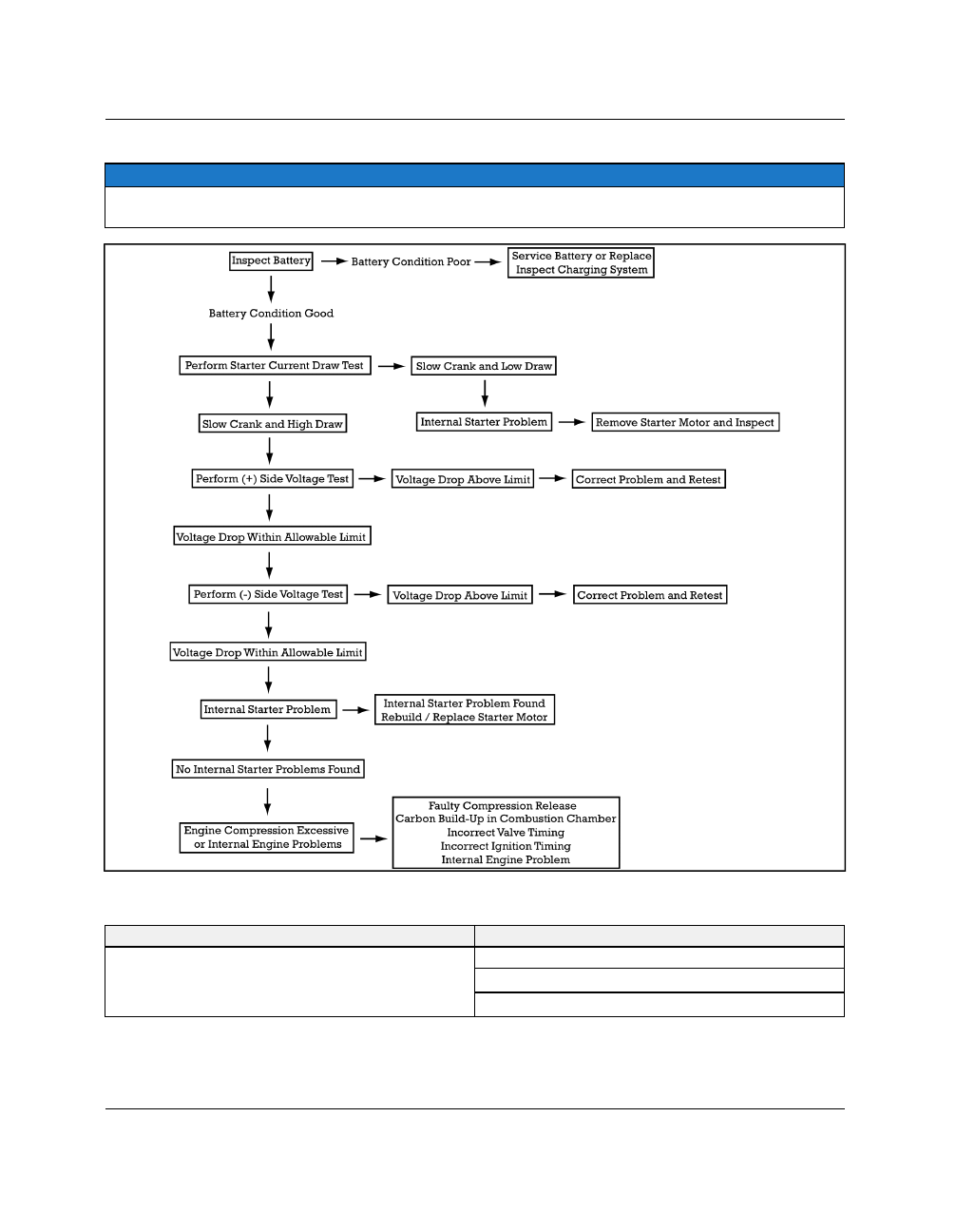
TTRROOUUBBLLEESSHHOOOOTTIINNGG FFLLOOW
W CCHHAARRTT 22
NOTE
These procedures require a Digital Multi Meter (DMM) and high a high current shunt, or an inductive ammeter
clamp and a DMM.
TTRROOUUBBLLEESSHHOOOOTTIINNGG FFLLOOW
W CCHHAARRTT 33
SYMPTOM
POSSIBLE CAUSE
Starter motor turns, but engine does not turn. The
starter motor can be heard spinning.
Starter clutch malfunction.
Starter torque limit clutch slipping.
Starter gears damage.