Indian motorcycle 2017. Service Manual - page 33
 

  Главная      Manuals     Indian motorcycle 2017. Service Manual


Search            copyright infringement  


Content      ..     31      32      33      34     ..


Indian motorcycle 2017. Service Manual - page 33


9

9.27

13. Slowly pump lever to set brake pads against disc.

Lever should be firm, not spongy. If lever is
spongy, inspect pad installation, bleed brake lines
and inspect brake disc.

14. Install reservoir cover and torque to specification.

TORQUE

Master Cylinder Reservoir Cover:

14 in-lbs (2 Nm)

15. Operate brake lever several times until lever is

firm and pressure can be felt.

WARNING

After pad installation or any brake system repair,

safely elevate wheel, apply and release brake pedal

or lever 2-3 times and release. Verify wheel turns

freely without drag. If brake drag is evident, do not

operate the motorcycle. Inspect vehicle to determine

cause and then repair as necessary.

RREEAARR BBRRAAKKEE PPAADD RREEPPLLAACCEEM

MEENNTT

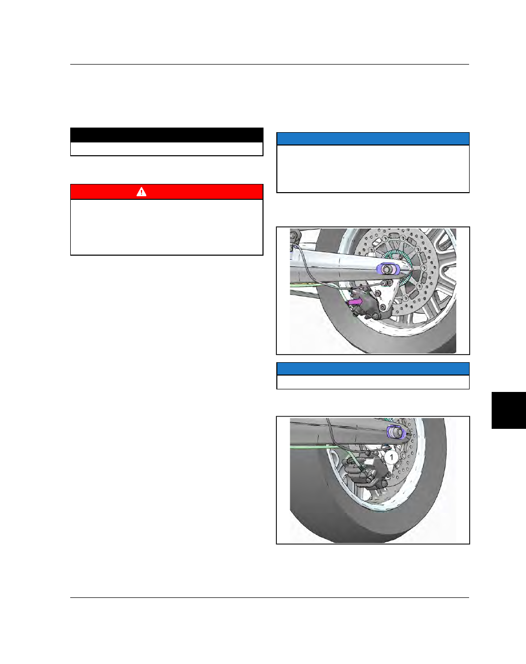
Always replace brake pads as a set. The rear pads can
be

changed

with

the

caliper

installed

on

the

motorcycle.

Do not attempt to remove the caliper from the bracket
with bracket installed.

NOTE

Brake fluid will be forced back into the reservoir

when pads are pushed back. Remove reservoir cover

and monitor fluid level, or attach a hose to the brake

bleeder screw and open the bleed screw while

pushing the pads and pistons back.

1.

Push caliper toward wheel to push pad and pistons
back

and

provide

clearance

for

new

pad

installation.

NOTE

The caliper should move freely on the guide pins.

2.

Slide retaining pin

q

out until inner pad can be

removed. Note orientation of spring plate.

BRAKES

9.28

9927618 R03 - 2017 Indian Motorcycle (Full-Size) Service Manual

3.

Slide inner pad out front edge of rear caliper.
Install new pad. Be sure backing plate is properly
installed on new pad with insulator between brake
pad and plate. Slide pad into place and engage
tab in the back of the caliper.

4.

Install new outer brake pad. Be sure tab is
engaged with caliper as it is for the inner pad.

5.

Apply silicone grease to O-ring on pad retaining
pin.

TORQUE

Brake Pad Retaining Pin:

120 in-lbs (14 Nm)

6.

Inspect fluid level in the reservoir and adjust as
necessary.

7.

Pump brake pedal slowly several times to set new
pads against disc, until lever is firm and pressure
can be felt.

8.

Bleed brake system if necessary.

WARNING

After pad installation or any brake system repair,

safely elevate wheel, apply and release brake pedal

or lever 2-3 times and release. Verify wheel turns

freely without drag. If rear brake drag is evident,

inspect pedal clearance. Do not operate the

motorcycle if drag is still evident after clearance

adjustment. Inspect vehicle to determine cause and

repair as necessary.

BBRRAAKKEE DDIISSCC IINNSSPPEECCTTIIOONN

1.

Visually inspect disc for cracks or damage.

2.

Measure brake disc thickness in several locations
around disc with a micrometer, and along

wear

surface

and compare to specifications. See Service

Specifications, page 9.4.

NOTE

Replace the brake disc if any measurement is worn

beyond the service limit.

3.

With disc mounted to wheel, inspect for brake disc
runout / warpage with a dial indicator and
compare

to

specifications.

See

Service

Specifications, page 9.4.

NOTE

Runout should be measured 2-4mm in from outside

edge of disc.

4.

Replace brake disc if dial indicator reading
displays excessive brake disc runout and other
possible causes have been eliminated.

BRAKES

9

9.29

FFRROONNTT M

MAASSTTEERR CCYYLLIINNDDEERR SSEERRVVIICCEE

CAUTION

Brake fluid and brake cleaners could damage paint,

plastics and some rubber compounds. Cover or

remove plastic and painted parts before working on

the brake system. If brake fluid is spilled on cosmetic

surfaces, immediately rinse the area with a mild

solution of soap and water until all traces of brake

fluid are removed. Be sure master cylinder reservoir

is level before removing cover.

NOTE

Replace all rubber parts upon assembly.

1.

Clean the master cylinder. Attach a drain hose to
caliper bleed screw and place the end in a
suitable container. Drain brake fluid from the front
brake system by slowly pumping brake lever.

2.

Remove the RH side mirror from the lever perch.

3.

Remove banjo fastener

q

and brake line from

master cylinder.

4.

Remove fasteners

w

, clamp, and master cylinder.

5.

Remove reservoir cover

e

and diaphragm

r

.

6.

Remove the circlip

t

and pivot pin

y

and pull

lever assembly out of master cylinder.

7.

Pull push rod

u

and dust boot

i

out of master

cylinder.

8.

Remove snap ring.

BRAKES

9.30

9927618 R03 - 2017 Indian Motorcycle (Full-Size) Service Manual

9.

Slide piston

o

out with spring. Note spring

orientation for assembly of new spring (new
parts).

10. Clean master cylinder with isopropyl alcohol and

dry with compressed air. DO NOT soak in alcohol
for

more

than

30

seconds.

DO

NOT

aim

pressurized air directly at the level sight glass.

11. Inspect cylinder bore and chamfer of bore for

corrosion, scratches, scoring, or pitting. Replace
master cylinder if any of these conditions are
evident.

12. Measure the diameter of the bore. Replace master

cylinder if worn beyond the service limit.

Master Cylinder Bore Diameter Service Limit:

.6886

in (17.49 mm)

13. Measure the diameter of the master cylinder

piston. Replace piston if worn beyond the Service
Limit.

Master Cylinder Piston Diameter Service Limit:

.6811

in (17.30 mm)

14. Clean the compensating port and supply port with

compressed air to be sure they are clean and
unobstructed.

15. Apply a light film of special lubricant from piston

kit to each piston seal cup.

16. Assemble the piston / spring assembly as shown.

Large diameter of beveled edge on piston cups
face toward spring. Install a new retaining ring on
end of piston with machined edge (sharpest of the
two edges).

17. Carefully install spring / piston assembly into

master cylinder bore. Work the front piston seal
carefully past the chamfer and into bore. Use care
not to damage or fold the seal when working it
past the chamfer.

18. Continue to install the piston until the rear seal is

past the chamfer. Push and hold the piston in far
enough to allow the retaining ring to be installed.

19. Be sure retaining ring is fully seated in the groove.

20. Clean the bore from the retaining ring outward, so

the outer edge of the new dust boot adheres
properly and will not dislodge from the bore.

21. Install new boot, seating the outer edge fully in the

bore and engage outer lip of boot in piston
groove.

22. Apply special lubricant from kit to brake lever

contact surface.

23. Install master cylinder on handlebar. Torque

clamp fasteners to specification.

TORQUE

Master Cylinder Clamp Fasteners:

70 in-lbs (8 Nm)

BRAKES

9

9.31

FFRROONNTT CCAALLIIPPEERR SSEERRVVIICCEE

CAUTION

Brake fluid and brake cleaners will damage paint,

plastics and some rubber compounds. Cover or

remove plastic and painted parts before working on

the brake system. If brake fluid is spilled on cosmetic

surfaces, immediately rinse the area with a mild

solution of soap and water until all traces of brake

fluid are removed. Make sure the master cylinder

reservoir being worked on is level before removing

the cap.

NOTE

Replace all rubber parts upon assembly. Keep parts

in order for assembly.

The top and bottom pistons in

the caliper are not the same size

.

1.

Remove two acorn nuts

q

and fastener

w

from

each side of the motorcycle and remove the
caliper covers

e

.

.

2.

Remove banjo fastener

q

, sealing washers, and

brake hose from caliper assembly and allow it to
drain into a container.

3.

Remove front caliper mounting studs

w

and

remove the caliper.

4.

Cover the end of brake line (s) to prevent debris
from entering.

5.

Cover the brake hose connection on the caliper
and clean the outer surfaces of caliper assembly
with brake cleaner (commercially available) or
isopropyl alcohol. Dry with compressed air.

6.

Remove pad retaining pin

e

and brake pads.

NOTE

Pads contaminated with oil or grease must be

replaced as a set.

BRAKES

9.32

9927618 R03 - 2017 Indian Motorcycle (Full-Size) Service Manual

7.

Remove the four caliper fasteners

r

using an E12

reverse Torx socket.

8.

Separate the halves. Note the O-ring

t

used to

seal the fluid passage. this O-ring must be
replaced along with all rubber parts during
assembly.

9.

Keep parts in order for assembly in the same bore.

Top and bottom pistons (in each caliper half) have
different diameters.

10. Remove each piston with a caliper piston pliers. If

a caliper piston pliers is not available, wrap the
caliper in a shop towel and apply short bursts of
compressed air through the brake line hole and
through the transfer passage to force the pistons
out of the bore.

11. Remove dust seals and piston seals. Use care not

to damage the seal bores.

12. Clean all parts thoroughly with isopropyl alcohol.

Be sure the seal bores are clean, removing all
traces of dirt or dried brake fluid.

13. Clean piston seal and dust seal bores to remove

residue that could cause the pistons to stick,
resulting in brake drag.

14. Inspect each piston bore for corrosion, scratches,

scoring, or pitting. Replace caliper if any of these
conditions are evident.

15. Measure the diameter of each caliper bore.

Replace caliper if any is worn beyond the service
limit.

Front Caliper Bore Diameter:

Standard = 30.23 mm | Limit = 30.31 mm (1.1933

in)

Standard = 33.96 mm | Limit = 34.04 mm (1.3401

in)

16. Measure the outside diameter of each piston in two

spots 90° apart, 5mm from outer edge. Repeat
measurement 5mm from inner edge. Replace
piston if worn beyond service limit at any
measuring point.

Front Caliper Piston Outside Diameter:

Standard = 30.15 mm | Limit = 30.09 mm (1.1846

in)

Standard = 33.91 mm | Limit = 33.85 mm (1.3327

in)

NOTE

Install all new rubber parts during assembly. Do not

reuse old seals or boots.

17. Apply special lubricant from service kit to new

piston seals and dust seals.

18. Apply special assembly oil (included in kit) to

outer surface of all pistons.

19. Install piston seals and dust seals in caliper body.

20. Install pistons in their respective bores.

21. Clean threads of each caliper body fastener. Be

sure threads are free from any oil, grease, or brake
fluid. Apply a few drops of Loctite 242 (Blue) non
permanent locking agent to the threads of each
fastener.

22. Install a new O-ring on fluid transfer passage,

assemble halves of caliper and start (4) fasteners
while holding pressure on halves to keep O-ring in
place.

23. Evenly tighten fasteners by hand until halves are

secured.

24. Torque caliper body fasteners to specification.

TORQUE

Caliper Body Fasteners:

20 ft-lbs (27 Nm)

BRAKES

9

9.33

25. Install

brake

pads.

Torque

retaining

pin

to

specification.

TORQUE

Brake Pad Retaining Pin:

120 in-lbs (14 Nm)

FFRROONNTT CCAALLIIPPEERR IINNSSTTAALLLLAATTIIOONN

1.

Clean mounting surfaces of caliper and fork leg.

2.

Apply brake cleaner or isopropyl alcohol to a
clean shop towel and wipe brake discs clean.

3.

Separate brake pads and install caliper assembly
over brake disc.

4.

Install caliper mounting studs and torque to
specification.

TORQUE

Caliper Mounting Studs:

35 ft-lbs (48 Nm)

5.

Connect brake hose to caliper with banjo fastener
and new sealing washers. Torque to specification.

TORQUE

Banjo Fastener (Brake Line):

18 ft-lbs (24 Nm)

6.

Fill and bleed the front brake hydraulic system.
See ABS Front Brake Bleeding, page 9.24.

WARNING

After pad installation or any brake system repair,

safely elevate the wheel, apply and release the brake

pedal or lever 2-3 times and release. Verify the wheel

turns freely without drag. If brake drag is evident, do

not operate the motorcycle. Inspect the vehicle to

determine the cause and then repair as necessary.

BRAKES

9.34

9927618 R03 - 2017 Indian Motorcycle (Full-Size) Service Manual

RREEAARR M

MAASSTTEERR CCYYLLIINNDDEERR SSEERRVVIICCEE

CAUTION

Brake fluid and brake cleaners will damage paint,

plastics and some rubber compounds. Cover or

remove plastic and painted parts before working on

the brake system. If brake fluid is spilled on cosmetic

surfaces, immediately rinse the area with a mild

solution of soap and water until all traces of brake

fluid are removed. Make sure the master cylinder

reservoir being worked on is level before removing

the cap. Replace all rubber parts upon assembly.

NOTE

Replace all rubber parts upon assembly.

1.

Remove brake line banjo fastener

q

, sealing

washers and brake line. Allow fluid to drain into a
container.

2.

Remove cotter pin

w

from push rod pin and

remove washer.

3.

Remove jamb nut

e

.

4.

Remove master cylinder from floorboard support.

5.

Remove external snap ring

r

, washer

t

and dust

boot

y

and return spring (not shown).

6.

Remove internal snap ring followed by piston and
cups.

7.

Inspect cylinder bore and chamfer on the front of
the bore for corrosion, scratches, scoring, or
pitting. Replace master cylinder if any of these
conditions are evident.

8.

Measure the bore diameter. Replace if worn
beyond

the

service

limit.

See

Service

Specifications, page 9.4.

9.

Clean compensating port and supply port with
compressed air to be sure they are clean and
unobstructed.

10. Clean all parts with clean Indian Motorcycle DOT

4 brake fluid or isopropyl alcohol.

11. Replace ALL RUBBER PARTS with new.

12. Carefully assemble the piston and cups into the

master cylinder bore.

BRAKES

9

9.35

13. Install the push rod, push rod retainer and internal

snap ring.

14. Install the return spring, dust boot, washer and

external snap ring.

15. Install the master cylinder and torque the jamb nut

and brake line banjo fastener to specification.

TORQUE

Brake Line Banjo Fastener:

18 ft-lbs (24 Nm)

Rear Master Cylinder Jamb Nut:

35 ft-lbs (48 Nm)

16. Install the push rod retaining pin, washer and

cotter pin.

RREEAARR CCAALLIIPPEERR SSEERRVVIICCEE

1.

Remove banjo fastener

q

and sealing washers

from rear caliper and allow fluid to drain into a
container.

2.

Remove caliper fasteners

w

and lower caliper off

of mounting bracket.

3.

Remove pin

e

and brake pads. Note orientation of

spring plate for assembly.

4.

Slide caliper bracket off pins and remove spring
plate.

BRAKES

9.36

9927618 R03 - 2017 Indian Motorcycle (Full-Size) Service Manual

5.

Remove caliper pistons. Keep pistons in order for
installation in their respective bores.

6.

Remove dust seals and piston seals. Use care not
to damage the seal bores.

7.

Clean caliper thoroughly with isopropyl alcohol.
Dry with compressed air. Clean seal grooves
thoroughly. Any residue left behind in the grooves
could cause caliper pistons to stick and result in
brake drag.

8.

Inspect each bore and surface of each piston for
corrosion, scratches, scoring, or pitting. Replace
caliper assembly if any of these conditions are
evident.

9.

Measure diameter of each bore and piston.
Replace caliper assembly or parts if worn beyond
service limit.

Caliper Piston Bore DiameterService Limit: 27.05 mm

(1.0649 in)

Caliper Piston DiameterService Limit: 26.935 mm

(1.0604 in)

10. Install all new rubber parts during assembly. Do

not reuse old seals or boots. Apply special
lubricant from service kit to new piston seals and
dust seals.

11. Apply special assembly oil to outer surface of all

pistons.

12. Install piston seals and dust seals in caliper body.

13. Install pistons in their respective bore.

14. Replace caliper pin boot on bracket and on

caliper. Apply special lubricant from service kit to
boots and both pins.

15. Assemble bracket to caliper. Remove excess

lubricant.

16. Install spring plate and outer brake pad. Start pad

pin through outer pad.

17. Install inner pad with insulator and backing plate.

18. Torque brake pad retaining pin to specification.

TORQUE

Brake Pad Retaining Pin:

120 in-lbs (14 Nm)

19. Be sure end tabs of pads are both fully engaged in

the heel plate on bracket.

20. Install caliper to bracket and torque caliper

fasteners to specification.

TORQUE

Caliper Fasteners:

31 ft-lbs (42 Nm)

21. Install brake line with new sealing washers and

torque banjo fastener to specification.

TORQUE

Banjo Fastener (Rear Caliper):

18 ft-lbs (24 Nm)

22. Bleed brake system. See ABS Rear Brake Bleeding,

page 9.23.

BRAKES

9

9.37

RREEAARR CCAALLIIPPEERR IINNSSTTAALLLLAATTIIOONN

1.

Install caliper to rear mounting bracket and torque
to specification.

TORQUE

Caliper Fasteners:

31 ft-lbs (42 Nm)

2.

Install brake hose, and banjo fastener with new
sealing washers.

TORQUE

Banjo Fastener (Rear Caliper):

18 ft-lbs (24 Nm)

3.

Fill and bleed the rear hydraulic brake system.
See ABS Rear Brake Bleeding, page 9.23.

WARNING

After pad installation or any brake system repair,

safely elevate the wheel, apply and release the brake

pedal or lever 2-3 times and release. Verify the wheel

turns freely without drag. If brake drag is evident, do

not operate the motorcycle. Inspect the vehicle to

determine the cause and then repair as necessary.

BRAKES

9.38

9927618 R03 - 2017 Indian Motorcycle (Full-Size) Service Manual

TTRROOUUBBLLEESSHHOOOOTTIINNGG

PROBLEM

POSSIBLE CAUSE

POSSIBLE REPAIR NEEDED

Weak Brakes or
Erratic Braking
Action

Fluid Leakage (External)
Fluid Leakage (Internal of Master Cylinder)
Worn Pads
Oil Contamination of Brake Pads and/or Brake
Disc
Air In System
Low Brake Fluid Level In Reservoir
Excessive Brake Disc Runout
Worn or Damaged Wheel Bearings
Loose Front Axle Nut or Clamps or Loose Rear
Axle
Caliper Mount Surface Uneven Or Misaligned;
Missing or Damaged Fasteners
Clogged or Restricted Hydraulic Line
Caliper Bracket Misaligned, Bent or Distorted
Loose Brake Disc
Brake Pads Glazed

Repair or Replace Leaking Component
Replace Master Cylinder
Replace Brake Pads
Pads Must Be Replaced. Disc May Be
Cleaned.
Bleed Air From System
Fill Reservoir, Bleed Brakes, Top Off Fluid
Level.
Replace Brake Disc.
Replace Wheel Bearings.
Torque Correctly
Inspect / Repair
Replace Line(s)
Replace Bracket
Install New Fasteners. Torque to
Specification
Replace Pads. Avoid Needless Heavy
Braking for 100-200 miles (Burnish New
Brake Pads).

Poor Brakes or
No Brakes When
First Applied.
Brake Lever
Pressure Present
If Lever Is
“Pumped”.

Air In System
Low Brake Fluid Level In Reservoir
Brake Disc is Bent or Warped
Caliper Misalignment
External Leak
Internal Leak (master cylinder)
Faulty Brake Hose

Bleed Air From System
Fill Reservoir, Bleed Brakes, Top Off Fluid
Level.
Replace Brake Disc
Determine Cause and Correct
Repair or Replace Damaged Component
Repair or Replace Master Cylinder
Inspect for Bulges / Replace

Brake Pedal or
Brake Lever
Pulsates

Brake Disc Bent or Warped
Mounting Surface of Brake Disc Uneven / Disc
Loose
Caliper Mount Surface Uneven Or Misaligned;
Missing or Damaged Fasteners

Replace Brake Disc
Repair or Replace as Necessary

Excessive Lever
or Pedal Travel /
Spongy Brake
Feel.

Air in System
Loose Mounting Hardware
Low Brake Fluid Level In Reservoir
Incorrect Brake Fluid Used
See “Weak / Erratic Brakes” and Poor Brakes”
possible causes above.

Bleed Air From System
Repair as Necessary
Fill Reservoir, Bleed Brakes, Top Off Fluid
Level.
Flush System and Replace With Correct
Fluid

Fluid Leakage

Loose Banjo Fittings
Damaged Banjo Fitting Sealing Washers
Cracked / Damaged Hose
Worn Master Cylinder Piston, Caliper Piston(s)
or Seals
Diaphragm (master Cylinder reservoir)
Leaking
Fluid level too high (new brake pads installed
without removing added fluid)

Tighten to Specified Torque
Replace
Replace
Repair / Replace Master Cylinder or
Wheel Caliper.
Inspect / Replace Cover, Cap, Diaphragm
or Reservoir as Required
Correct fluid level

BRAKES

9

9.39

PROBLEM

POSSIBLE CAUSE

POSSIBLE REPAIR NEEDED

Brakes Drag
Excessively or
Self-Apply
(Brakes
Overheat)

Reservoir Over Filled
Brake Pedal Or Lever Not Returning
Completely To Rest Position
Inadequate Freeplay
Compensating Port Plugged
Internal Corrosion of Components (Master
Cylinder / Caliper)
Rear Caliper: Corrosion of Sliding Parts, Bent
or Damaged Parts
Contaminated Brake Fluid
Caliper Pistons Sticking
Rider Error (Operator Riding Brakes)

Adjust Level As Necessary
Inspect Linkage, Pivots and Mechanism
For Cause Of Binding Or Restricted
Movement;
Measure Pedal Clearance / Adjust
Repair or Replace Master Cylinder
Replace Damaged Component
Repair or Replace As Necessary
Flush System, Install Correct Fluid
Repair / Replace Caliper (Corrosion /
Buildup of Residue In Caliper Piston Seal
Grooves)
Educate Operator

Brake Squeal/
Squeak

If noise is minor and inconsistent, some brake
squeak / squeal is characteristic of disc brakes
and usually caused by dust / dirt on pads and /
or brake disc.
Pad Not Secure in Caliper
Aftermarket (not genuine Indian Motorcycle)
Parts
Worn or Damaged Wheel Bearing(s)
Worn Pads / Disc

Apply non oil-based solvent to a clean
shop towel and wipe dust / dirt from
brake disc.
Repair as Necessary. Inspect Pad
Installation
Install Genuine Indian Motorcycle Parts
Replace
Replace

BRAKES

10

10.1

ELECTRICAL

CHAPTER 10

ELECTRICAL

STARTING / CHARGING. . . . . . . . . . . . . . . . . . . . . . . . . . . . . . . . . . . . . . . . . . . . . . . . . . . . . . . . . . . . . . . . . . . . . . . . . . . . . . . .10.5

GENERAL INFORMATION

. . . . . . . . . . . . . . . . . . . . . . . . . . . . . . . . . . . . . . . . . . . . . . . . . . . . . . . . . . . . . . . . . . . . . . . . . . . .10.5

SERVICE NOTES

. . . . . . . . . . . . . . . . . . . . . . . . . . . . . . . . . . . . . . . . . . . . . . . . . . . . . . . . . . . . . . . . . . . . . . . . . . . . . . . .10.5

SPECIAL TOOLS

. . . . . . . . . . . . . . . . . . . . . . . . . . . . . . . . . . . . . . . . . . . . . . . . . . . . . . . . . . . . . . . . . . . . . . . . . . . . . . . . .10.6

TORQUE SPECIFICATIONS

. . . . . . . . . . . . . . . . . . . . . . . . . . . . . . . . . . . . . . . . . . . . . . . . . . . . . . . . . . . . . . . . . . . . . .10.6

SERVICE SPECIFICATIONS - STARTING / CHARGING

. . . . . . . . . . . . . . . . . . . . . . . . . . . . . . . . . . . . . . . . . .10.7

ASSEMBLY VIEWS

. . . . . . . . . . . . . . . . . . . . . . . . . . . . . . . . . . . . . . . . . . . . . . . . . . . . . . . . . . . . . . . . . . . . . . . . . . . . . . . . . . . .10.8

STARTER MOTOR / SOLENOID

. . . . . . . . . . . . . . . . . . . . . . . . . . . . . . . . . . . . . . . . . . . . . . . . . . . . . . . . . . . . . . . . . .10.8

STATOR

. . . . . . . . . . . . . . . . . . . . . . . . . . . . . . . . . . . . . . . . . . . . . . . . . . . . . . . . . . . . . . . . . . . . . . . . . . . . . . . . . . . . . . . . .10.9

REGULATOR / RECTIFIER

. . . . . . . . . . . . . . . . . . . . . . . . . . . . . . . . . . . . . . . . . . . . . . . . . . . . . . . . . . . . . . . . . . . . . 10.10

BATTERY BOX

. . . . . . . . . . . . . . . . . . . . . . . . . . . . . . . . . . . . . . . . . . . . . . . . . . . . . . . . . . . . . . . . . . . . . . . . . . . . . . . . . 10.11

BATTERY SERVICE

. . . . . . . . . . . . . . . . . . . . . . . . . . . . . . . . . . . . . . . . . . . . . . . . . . . . . . . . . . . . . . . . . . . . . . . . . . . . . . . . . 10.12

BATTERY REMOVAL

. . . . . . . . . . . . . . . . . . . . . . . . . . . . . . . . . . . . . . . . . . . . . . . . . . . . . . . . . . . . . . . . . . . . . . . . . . . 10.12

BATTERY INSTALLATION

. . . . . . . . . . . . . . . . . . . . . . . . . . . . . . . . . . . . . . . . . . . . . . . . . . . . . . . . . . . . . . . . . . . . . . 10.13

BATTERY BOX REMOVAL

. . . . . . . . . . . . . . . . . . . . . . . . . . . . . . . . . . . . . . . . . . . . . . . . . . . . . . . . . . . . . . . . . . . . . . 10.13

BATTERY BOX INSTALLATION

. . . . . . . . . . . . . . . . . . . . . . . . . . . . . . . . . . . . . . . . . . . . . . . . . . . . . . . . . . . . . . . . . 10.14

BATTERY CHARGING - NEW BATTERY

. . . . . . . . . . . . . . . . . . . . . . . . . . . . . . . . . . . . . . . . . . . . . . . . . . . . . . . . 10.15

BATTERY CHARGING - IN SERVICE

. . . . . . . . . . . . . . . . . . . . . . . . . . . . . . . . . . . . . . . . . . . . . . . . . . . . . . . . . . . 10.16

BATTERY INSPECTION

. . . . . . . . . . . . . . . . . . . . . . . . . . . . . . . . . . . . . . . . . . . . . . . . . . . . . . . . . . . . . . . . . . . . . . . . 10.16

BATTERY TESTING

. . . . . . . . . . . . . . . . . . . . . . . . . . . . . . . . . . . . . . . . . . . . . . . . . . . . . . . . . . . . . . . . . . . . . . . . . . . . 10.16

STARTER MOTOR SERVICE

. . . . . . . . . . . . . . . . . . . . . . . . . . . . . . . . . . . . . . . . . . . . . . . . . . . . . . . . . . . . . . . . . . . . . . . . 10.17

SAFETY INFORMATION

. . . . . . . . . . . . . . . . . . . . . . . . . . . . . . . . . . . . . . . . . . . . . . . . . . . . . . . . . . . . . . . . . . . . . . . 10.17

STARTING SYSTEM DIAGNOSTIC TABLE

. . . . . . . . . . . . . . . . . . . . . . . . . . . . . . . . . . . . . . . . . . . . . . . . . . . . . . 10.17

STARTER CIRCUIT DIAGRAM

. . . . . . . . . . . . . . . . . . . . . . . . . . . . . . . . . . . . . . . . . . . . . . . . . . . . . . . . . . . . . . . . . 10.18

TROUBLESHOOTING FLOW CHART 1

. . . . . . . . . . . . . . . . . . . . . . . . . . . . . . . . . . . . . . . . . . . . . . . . . . . . . . . . . 10.19

TROUBLESHOOTING FLOW CHART 2

. . . . . . . . . . . . . . . . . . . . . . . . . . . . . . . . . . . . . . . . . . . . . . . . . . . . . . . . . 10.20

TROUBLESHOOTING FLOW CHART 3

. . . . . . . . . . . . . . . . . . . . . . . . . . . . . . . . . . . . . . . . . . . . . . . . . . . . . . . . . 10.20

STARTING SYSTEM TESTS

. . . . . . . . . . . . . . . . . . . . . . . . . . . . . . . . . . . . . . . . . . . . . . . . . . . . . . . . . . . . . . . . . . . . . . . . . . 10.21

BATTERY LOAD TEST

. . . . . . . . . . . . . . . . . . . . . . . . . . . . . . . . . . . . . . . . . . . . . . . . . . . . . . . . . . . . . . . . . . . . . . . . . 10.21

STARTER SOLENOID GROUND CIRCUIT TEST

. . . . . . . . . . . . . . . . . . . . . . . . . . . . . . . . . . . . . . . . . . . . . . . . 10.21

GEAR POSITION SWITCH NEUTRAL INDICATOR TEST

. . . . . . . . . . . . . . . . . . . . . . . . . . . . . . . . . . . . . . . . 10.22

CLUTCH SWITCH CIRCUIT TEST

. . . . . . . . . . . . . . . . . . . . . . . . . . . . . . . . . . . . . . . . . . . . . . . . . . . . . . . . . . . . . . 10.23

CLUTCH SWITCH REMOVAL / INSTALLATION

. . . . . . . . . . . . . . . . . . . . . . . . . . . . . . . . . . . . . . . . . . . . . . . . 10.23

STARTER SOLENOID POSITIVE CIRCUIT TEST

. . . . . . . . . . . . . . . . . . . . . . . . . . . . . . . . . . . . . . . . . . . . . . . . 10.24

STARTER CURRENT DRAW TEST

. . . . . . . . . . . . . . . . . . . . . . . . . . . . . . . . . . . . . . . . . . . . . . . . . . . . . . . . . . . . . . 10.24

STARTER CLUTCH REMOVAL

. . . . . . . . . . . . . . . . . . . . . . . . . . . . . . . . . . . . . . . . . . . . . . . . . . . . . . . . . . . . . . . . . 10.25

STARTER MOTOR, REMOVAL / INSTALLATION

. . . . . . . . . . . . . . . . . . . . . . . . . . . . . . . . . . . . . . . . . . . . . . . . 10.25

CHARGING SYSTEM SERVICE

. . . . . . . . . . . . . . . . . . . . . . . . . . . . . . . . . . . . . . . . . . . . . . . . . . . . . . . . . . . . . . . . . . . . . 10.26

TROUBLESHOOTING, CHARGING SYSTEM

. . . . . . . . . . . . . . . . . . . . . . . . . . . . . . . . . . . . . . . . . . . . . . . . . . . 10.26

CURRENT DRAIN INSPECTION

. . . . . . . . . . . . . . . . . . . . . . . . . . . . . . . . . . . . . . . . . . . . . . . . . . . . . . . . . . . . . . . . 10.27

REGULATED VOLTAGE / AMPERAGE OUTPUT INSPECTION (ALL MODELS)

. . . . . . . . . . . . . . . . . . 10.27

STATOR AC VOLTAGE OUTPUT TEST

. . . . . . . . . . . . . . . . . . . . . . . . . . . . . . . . . . . . . . . . . . . . . . . . . . . . . . . . . 10.28

STATOR RESISTANCE TEST

. . . . . . . . . . . . . . . . . . . . . . . . . . . . . . . . . . . . . . . . . . . . . . . . . . . . . . . . . . . . . . . . . . . 10.29

10.2

9927618 R03 - 2017 Indian Motorcycle (Full-Size) Service Manual

STATOR WINDINGS TO GROUND INSPECTION

. . . . . . . . . . . . . . . . . . . . . . . . . . . . . . . . . . . . . . . . . . . . . . . . . . . . 10.30

STATOR REMOVAL

. . . . . . . . . . . . . . . . . . . . . . . . . . . . . . . . . . . . . . . . . . . . . . . . . . . . . . . . . . . . . . . . . . . . . . . . . . . . . . . . . 10.30

STATOR INSTALLATION

. . . . . . . . . . . . . . . . . . . . . . . . . . . . . . . . . . . . . . . . . . . . . . . . . . . . . . . . . . . . . . . . . . . . . . . . . . . . 10.31

FLYWHEEL REMOVAL

. . . . . . . . . . . . . . . . . . . . . . . . . . . . . . . . . . . . . . . . . . . . . . . . . . . . . . . . . . . . . . . . . . . . . . . . . . . . . . 10.32

RECTIFIER / REGULATOR CONNECTOR INSPECTION

. . . . . . . . . . . . . . . . . . . . . . . . . . . . . . . . . . . . . . . . . . . . . 10.32

DIODE LEAKAGE TEST

. . . . . . . . . . . . . . . . . . . . . . . . . . . . . . . . . . . . . . . . . . . . . . . . . . . . . . . . . . . . . . . . . . . . . . . . . . . . . 10.32

REGULATOR / RECTIFIER REPLACEMENT

. . . . . . . . . . . . . . . . . . . . . . . . . . . . . . . . . . . . . . . . . . . . . . . . . . . . . . . . . 10.33

IGNITION SYSTEM . . . . . . . . . . . . . . . . . . . . . . . . . . . . . . . . . . . . . . . . . . . . . . . . . . . . . . . . . . . . . . . . . . . . . . . . . . . . . . . . . . . . . . . . . 10.34

GENERAL INFORMATION

. . . . . . . . . . . . . . . . . . . . . . . . . . . . . . . . . . . . . . . . . . . . . . . . . . . . . . . . . . . . . . . . . . . . . . . . . . . . . . . 10.34

SERVICE NOTES

. . . . . . . . . . . . . . . . . . . . . . . . . . . . . . . . . . . . . . . . . . . . . . . . . . . . . . . . . . . . . . . . . . . . . . . . . . . . . . . . . . . 10.34

SPECIAL TOOLS

. . . . . . . . . . . . . . . . . . . . . . . . . . . . . . . . . . . . . . . . . . . . . . . . . . . . . . . . . . . . . . . . . . . . . . . . . . . . . . . . . . . . 10.34

TORQUE SPECIFICATIONS

. . . . . . . . . . . . . . . . . . . . . . . . . . . . . . . . . . . . . . . . . . . . . . . . . . . . . . . . . . . . . . . . . . . . . . . . . 10.34

SERVICE SPECIFICATIONS

. . . . . . . . . . . . . . . . . . . . . . . . . . . . . . . . . . . . . . . . . . . . . . . . . . . . . . . . . . . . . . . . . . . . . . . . 10.34

TROUBLESHOOTING

. . . . . . . . . . . . . . . . . . . . . . . . . . . . . . . . . . . . . . . . . . . . . . . . . . . . . . . . . . . . . . . . . . . . . . . . . . . . . . . . . . . . 10.35

BASICS

. . . . . . . . . . . . . . . . . . . . . . . . . . . . . . . . . . . . . . . . . . . . . . . . . . . . . . . . . . . . . . . . . . . . . . . . . . . . . . . . . . . . . . . . . . . . . 10.35

TEST LEAD ADAPTER KIT

. . . . . . . . . . . . . . . . . . . . . . . . . . . . . . . . . . . . . . . . . . . . . . . . . . . . . . . . . . . . . . . . . . . . . . . . . . 10.35

ECM CONNECTOR MAP

. . . . . . . . . . . . . . . . . . . . . . . . . . . . . . . . . . . . . . . . . . . . . . . . . . . . . . . . . . . . . . . . . . . . . . . . . . . 10.36

IGNITION SYSTEM TEST FLOWCHART

. . . . . . . . . . . . . . . . . . . . . . . . . . . . . . . . . . . . . . . . . . . . . . . . . . . . . . . . . . . . . 10.36

BATTERY VOLTAGE INSPECTION: TEST 1

. . . . . . . . . . . . . . . . . . . . . . . . . . . . . . . . . . . . . . . . . . . . . . . . . . . . . . . . . . 10.37

SPARK INSPECTION: TEST 2

. . . . . . . . . . . . . . . . . . . . . . . . . . . . . . . . . . . . . . . . . . . . . . . . . . . . . . . . . . . . . . . . . . . . . . . . 10.37

IGNITION CABLE RESISTANCE: TEST 3

. . . . . . . . . . . . . . . . . . . . . . . . . . . . . . . . . . . . . . . . . . . . . . . . . . . . . . . . . . . . 10.37

IGNITION COIL POWER & GROUND SIGNAL TEST 4

. . . . . . . . . . . . . . . . . . . . . . . . . . . . . . . . . . . . . . . . . . . . . . . 10.38

IGNITION COIL RESISTANCE: TEST 5

. . . . . . . . . . . . . . . . . . . . . . . . . . . . . . . . . . . . . . . . . . . . . . . . . . . . . . . . . . . . . . 10.39

CRANKSHAFT POSITION SENSOR (CPS) RESISTANCE INSPECTION:

. . . . . . . . . . . . . . . . . . . . . . . . . . . . . . . 10.39

IGNITION COIL REMOVAL / INSTALLATION

. . . . . . . . . . . . . . . . . . . . . . . . . . . . . . . . . . . . . . . . . . . . . . . . . . . . . . . 10.40

CHASSIS ELECTRICAL. . . . . . . . . . . . . . . . . . . . . . . . . . . . . . . . . . . . . . . . . . . . . . . . . . . . . . . . . . . . . . . . . . . . . . . . . . . . . . . . . . . . . 10.41

GENERAL INFORMATION

. . . . . . . . . . . . . . . . . . . . . . . . . . . . . . . . . . . . . . . . . . . . . . . . . . . . . . . . . . . . . . . . . . . . . . . . . . . . . . . 10.41

SERVICE NOTES

. . . . . . . . . . . . . . . . . . . . . . . . . . . . . . . . . . . . . . . . . . . . . . . . . . . . . . . . . . . . . . . . . . . . . . . . . . . . . . . . . . . 10.41

SPECIAL TOOLS

. . . . . . . . . . . . . . . . . . . . . . . . . . . . . . . . . . . . . . . . . . . . . . . . . . . . . . . . . . . . . . . . . . . . . . . . . . . . . . . . . . . . 10.41

TORQUE SPECIFICATIONS

. . . . . . . . . . . . . . . . . . . . . . . . . . . . . . . . . . . . . . . . . . . . . . . . . . . . . . . . . . . . . . . . . . . . . . . . . 10.41

ASSEMBLY VIEWS

. . . . . . . . . . . . . . . . . . . . . . . . . . . . . . . . . . . . . . . . . . . . . . . . . . . . . . . . . . . . . . . . . . . . . . . . . . . . . . . . . . . . . . . 10.42

HEAD LIGHT

. . . . . . . . . . . . . . . . . . . . . . . . . . . . . . . . . . . . . . . . . . . . . . . . . . . . . . . . . . . . . . . . . . . . . . . . . . . . . . . . . . . . . . . 10.42

TAIL LIGHT / LICENSE PLATE LIGHT

. . . . . . . . . . . . . . . . . . . . . . . . . . . . . . . . . . . . . . . . . . . . . . . . . . . . . . . . . . . . . . . 10.43

FUSE BOX

. . . . . . . . . . . . . . . . . . . . . . . . . . . . . . . . . . . . . . . . . . . . . . . . . . . . . . . . . . . . . . . . . . . . . . . . . . . . . . . . . . . . . . . . . . . . . . . 10.44

FUSE BOX LOCATION

. . . . . . . . . . . . . . . . . . . . . . . . . . . . . . . . . . . . . . . . . . . . . . . . . . . . . . . . . . . . . . . . . . . . . . . . . . . . . . 10.44

FUSE APPLICATION CHART

. . . . . . . . . . . . . . . . . . . . . . . . . . . . . . . . . . . . . . . . . . . . . . . . . . . . . . . . . . . . . . . . . . . . . . . . 10.45

VEHICLE CONTROL MODULE (VCM)

. . . . . . . . . . . . . . . . . . . . . . . . . . . . . . . . . . . . . . . . . . . . . . . . . . . . . . . . . . . . . . . . . . . 10.47

VEHICLE CONTROL MODULE (VCM) SERVICE NOTES

. . . . . . . . . . . . . . . . . . . . . . . . . . . . . . . . . . . . . . . . . . . . 10.47

VEHICLE CONTROL MODULE (VCM), REMOVAL / INSTALLATION

. . . . . . . . . . . . . . . . . . . . . . . . . . . . . . . . 10.48

VCM CONNECTOR MAP

. . . . . . . . . . . . . . . . . . . . . . . . . . . . . . . . . . . . . . . . . . . . . . . . . . . . . . . . . . . . . . . . . . . . . . . . . . . 10.49

HEADLIGHT SERVICE

. . . . . . . . . . . . . . . . . . . . . . . . . . . . . . . . . . . . . . . . . . . . . . . . . . . . . . . . . . . . . . . . . . . . . . . . . . . . . . . . . . . 10.52

HEADLIGHT BULB REPLACEMENT - ALL MODELS

. . . . . . . . . . . . . . . . . . . . . . . . . . . . . . . . . . . . . . . . . . . . . . . . . . 10.52

HEADLIGHT WARNING INDICATORS

. . . . . . . . . . . . . . . . . . . . . . . . . . . . . . . . . . . . . . . . . . . . . . . . . . . . . . . . . . . . . . 10.53

HORN SERVICE

. . . . . . . . . . . . . . . . . . . . . . . . . . . . . . . . . . . . . . . . . . . . . . . . . . . . . . . . . . . . . . . . . . . . . . . . . . . . . . . . . . . . . . . . . 10.54

GENERAL OVERIEW

. . . . . . . . . . . . . . . . . . . . . . . . . . . . . . . . . . . . . . . . . . . . . . . . . . . . . . . . . . . . . . . . . . . . . . . . . . . . . . . 10.54

LOAD SIDE TESTING

. . . . . . . . . . . . . . . . . . . . . . . . . . . . . . . . . . . . . . . . . . . . . . . . . . . . . . . . . . . . . . . . . . . . . . . . . . . . . . . 10.54

SWITCH SIDE TESTING

. . . . . . . . . . . . . . . . . . . . . . . . . . . . . . . . . . . . . . . . . . . . . . . . . . . . . . . . . . . . . . . . . . . . . . . . . . . . 10.54

ELECTRICAL

10

10.3

HORN BREAKOUT DIAGRAM

. . . . . . . . . . . . . . . . . . . . . . . . . . . . . . . . . . . . . . . . . . . . . . . . . . . . . . . . . . . . . . . . . . . . . . . 10.55

HORN REMOVAL / INSTALLATION

. . . . . . . . . . . . . . . . . . . . . . . . . . . . . . . . . . . . . . . . . . . . . . . . . . . . . . . . . . . . . . . . . 10.56

TAIL LIGHT SERVICE

. . . . . . . . . . . . . . . . . . . . . . . . . . . . . . . . . . . . . . . . . . . . . . . . . . . . . . . . . . . . . . . . . . . . . . . . . . . . . . . . . . . . 10.57

LED TAIL / BRAKE LIGHT OPERATION

. . . . . . . . . . . . . . . . . . . . . . . . . . . . . . . . . . . . . . . . . . . . . . . . . . . . . . . . . . . . . 10.57

TAIL / BRAKE / LICENSE PLATE LIGHT, REMOVAL / INSTALLATION

. . . . . . . . . . . . . . . . . . . . . . . . . . . . . . . 10.57

TRUNK LED REPLACEMENT - BRAKE / INTERIOR (ROADMASTER)

. . . . . . . . . . . . . . . . . . . . . . . . . . . . . . . . . 10.59

TURN SIGNAL / HAZARD SYSTEM SERVICE

. . . . . . . . . . . . . . . . . . . . . . . . . . . . . . . . . . . . . . . . . . . . . . . . . . . . . . . . . . . . . 10.60

TURN SIGNAL OPERATION

. . . . . . . . . . . . . . . . . . . . . . . . . . . . . . . . . . . . . . . . . . . . . . . . . . . . . . . . . . . . . . . . . . . . . . . . . 10.60

FRONT TURN SIGNAL REMOVAL / INSTALLATION (CHIEFTAIN / ROADMASTER)

. . . . . . . . . . . . . . . . . . 10.60

FRONT TURN SIGNAL, REMOVAL / INSTALLATION (CLASSIC / VINTAGE / DARK HORSE)

. . . . . . . . . 10.60

REAR TURN SIGNAL,REMOVAL / INSTALLATION (ALL MODELS)

. . . . . . . . . . . . . . . . . . . . . . . . . . . . . . . . . . . 10.61

INSTRUMENTATION

. . . . . . . . . . . . . . . . . . . . . . . . . . . . . . . . . . . . . . . . . . . . . . . . . . . . . . . . . . . . . . . . . . . . . . . . . . . . . . . . . . . . . 10.62

INSTRUMENT CLUSTER (CHIEF CLASSIC / CHIEF VINTAGE /CHIEF DARK HORSE /

SPRINGFIELD)

. . . . . . . . . . . . . . . . . . . . . . . . . . . . . . . . . . . . . . . . . . . . . . . . . . . . . . . . . . . . . . . . . . . . . . . . . . . . . . . . . . . 10.62

INSTRUMENT CLUSTER (CHIEFTAIN DARK HORSE)

. . . . . . . . . . . . . . . . . . . . . . . . . . . . . . . . . . . . . . . . . . . . . . . . 10.66

INSTRUMENT CLUSTER (CHIEFTAIN / ROADMASTER)

. . . . . . . . . . . . . . . . . . . . . . . . . . . . . . . . . . . . . . . . . . . . . 10.68

SPEEDOMETER DISPLAY

. . . . . . . . . . . . . . . . . . . . . . . . . . . . . . . . . . . . . . . . . . . . . . . . . . . . . . . . . . . . . . . . . . . . . . 10.68

TACHOMETER DISPLAY

. . . . . . . . . . . . . . . . . . . . . . . . . . . . . . . . . . . . . . . . . . . . . . . . . . . . . . . . . . . . . . . . . . . . . . . 10.70

RIDE COMMAND SYSTEM

. . . . . . . . . . . . . . . . . . . . . . . . . . . . . . . . . . . . . . . . . . . . . . . . . . . . . . . . . . . . . . . . . . . . . . . . . . . . . . 10.72

OVERVIEW

. . . . . . . . . . . . . . . . . . . . . . . . . . . . . . . . . . . . . . . . . . . . . . . . . . . . . . . . . . . . . . . . . . . . . . . . . . . . . . . . . . . . . . . . 10.72

HAND CONTROLS

. . . . . . . . . . . . . . . . . . . . . . . . . . . . . . . . . . . . . . . . . . . . . . . . . . . . . . . . . . . . . . . . . . . . . . . . . . . . . . . . . . 10.72

TRIGGER CONTROLS

. . . . . . . . . . . . . . . . . . . . . . . . . . . . . . . . . . . . . . . . . . . . . . . . . . . . . . . . . . . . . . . . . . . . . . . . . . . . . . 10.72

AUDIO CONTROLS

. . . . . . . . . . . . . . . . . . . . . . . . . . . . . . . . . . . . . . . . . . . . . . . . . . . . . . . . . . . . . . . . . . . . . . . . . . . . . . . . . 10.73

MAP CONTROLS

. . . . . . . . . . . . . . . . . . . . . . . . . . . . . . . . . . . . . . . . . . . . . . . . . . . . . . . . . . . . . . . . . . . . . . . . . . . . . . . . . . . 10.73

RIDE COMMAND™ SETTINGS

. . . . . . . . . . . . . . . . . . . . . . . . . . . . . . . . . . . . . . . . . . . . . . . . . . . . . . . . . . . . . . . . . . . . . 10.73

GENERAL

. . . . . . . . . . . . . . . . . . . . . . . . . . . . . . . . . . . . . . . . . . . . . . . . . . . . . . . . . . . . . . . . . . . . . . . . . . . . . . . . . . . . . . . . . . 10.75

TIME

. . . . . . . . . . . . . . . . . . . . . . . . . . . . . . . . . . . . . . . . . . . . . . . . . . . . . . . . . . . . . . . . . . . . . . . . . . . . . . . . . . . . . . . . . . . . . . . 10.75

AUDIO

. . . . . . . . . . . . . . . . . . . . . . . . . . . . . . . . . . . . . . . . . . . . . . . . . . . . . . . . . . . . . . . . . . . . . . . . . . . . . . . . . . . . . . . . . . . . . 10.76

VEHICLE

. . . . . . . . . . . . . . . . . . . . . . . . . . . . . . . . . . . . . . . . . . . . . . . . . . . . . . . . . . . . . . . . . . . . . . . . . . . . . . . . . . . . . . . . . . . 10.76

DOWNLOAD NEW SOFTWARE

. . . . . . . . . . . . . . . . . . . . . . . . . . . . . . . . . . . . . . . . . . . . . . . . . . . . . . . . . . . . . . . . . . . . . 10.77

ON YOUR PERSONAL COMPUTER

. . . . . . . . . . . . . . . . . . . . . . . . . . . . . . . . . . . . . . . . . . . . . . . . . . . . . . . . . . . . . . . . . . 10.77

ON YOUR MOTORCYCLE

. . . . . . . . . . . . . . . . . . . . . . . . . . . . . . . . . . . . . . . . . . . . . . . . . . . . . . . . . . . . . . . . . . . . . . . . . . 10.77

ON YOUR RIDE COMMAND™ DISPLAY SCREEN

. . . . . . . . . . . . . . . . . . . . . . . . . . . . . . . . . . . . . . . . . . . . . . . . . . . 10.77

DOWNLOAD NEW MAPS

. . . . . . . . . . . . . . . . . . . . . . . . . . . . . . . . . . . . . . . . . . . . . . . . . . . . . . . . . . . . . . . . . . . . . . . . . . . 10.78

ON YOUR MOTORCYCLE

. . . . . . . . . . . . . . . . . . . . . . . . . . . . . . . . . . . . . . . . . . . . . . . . . . . . . . . . . . . . . . . . . . . . . . . . . . 10.78

ON YOUR RIDE COMMAND™ DISPLAY SCREEN

. . . . . . . . . . . . . . . . . . . . . . . . . . . . . . . . . . . . . . . . . . . . . . . . . . . 10.78

ON YOUR PERSONAL COMPUTER

. . . . . . . . . . . . . . . . . . . . . . . . . . . . . . . . . . . . . . . . . . . . . . . . . . . . . . . . . . . . . . . . . . 10.78

ON YOUR MOTORCYCLE

. . . . . . . . . . . . . . . . . . . . . . . . . . . . . . . . . . . . . . . . . . . . . . . . . . . . . . . . . . . . . . . . . . . . . . . . . . 10.78

ON YOUR RIDE COMMAND™ DISPLAY SCREEN

. . . . . . . . . . . . . . . . . . . . . . . . . . . . . . . . . . . . . . . . . . . . . . . . . . . 10.78

RIDE COMMAND DIAGNOSTICS / TROUBLESHOOTING

. . . . . . . . . . . . . . . . . . . . . . . . . . . . . . . . . . . . . . . . . . . 10.79

CRUISE CONTROL

. . . . . . . . . . . . . . . . . . . . . . . . . . . . . . . . . . . . . . . . . . . . . . . . . . . . . . . . . . . . . . . . . . . . . . . . . . . . . . . . . . . . . . 10.82

CRUISE CONTROL OVERVIEW

. . . . . . . . . . . . . . . . . . . . . . . . . . . . . . . . . . . . . . . . . . . . . . . . . . . . . . . . . . . . . . . . . . . . . 10.82

CRUISE CONTROL DIAGNOSTICS

. . . . . . . . . . . . . . . . . . . . . . . . . . . . . . . . . . . . . . . . . . . . . . . . . . . . . . . . . . . . . . . . . 10.83

SECURITY ALARM

. . . . . . . . . . . . . . . . . . . . . . . . . . . . . . . . . . . . . . . . . . . . . . . . . . . . . . . . . . . . . . . . . . . . . . . . . . . . . . . . . . . . . . . 10.84

POWER WINDSHIELD

. . . . . . . . . . . . . . . . . . . . . . . . . . . . . . . . . . . . . . . . . . . . . . . . . . . . . . . . . . . . . . . . . . . . . . . . . . . . . . . . . . . 10.86

POWER WINDSHIELD OPERATION

. . . . . . . . . . . . . . . . . . . . . . . . . . . . . . . . . . . . . . . . . . . . . . . . . . . . . . . . . . . . . . . . . 10.86

POWER WINDSHIELD MOTOR, REMOVAL

. . . . . . . . . . . . . . . . . . . . . . . . . . . . . . . . . . . . . . . . . . . . . . . . . . . . . . . . . 10.87

ELECTRICAL


Content      ..     31      32      33      34     ..