Indian motorcycle 2017. Service Manual - page 32
 

  Главная      Manuals     Indian motorcycle 2017. Service Manual


Search            copyright infringement  


Content      ..     30      31      32      33     ..


Indian motorcycle 2017. Service Manual - page 32


9.10

9927618 R03 - 2017 Indian Motorcycle (Full-Size) Service Manual

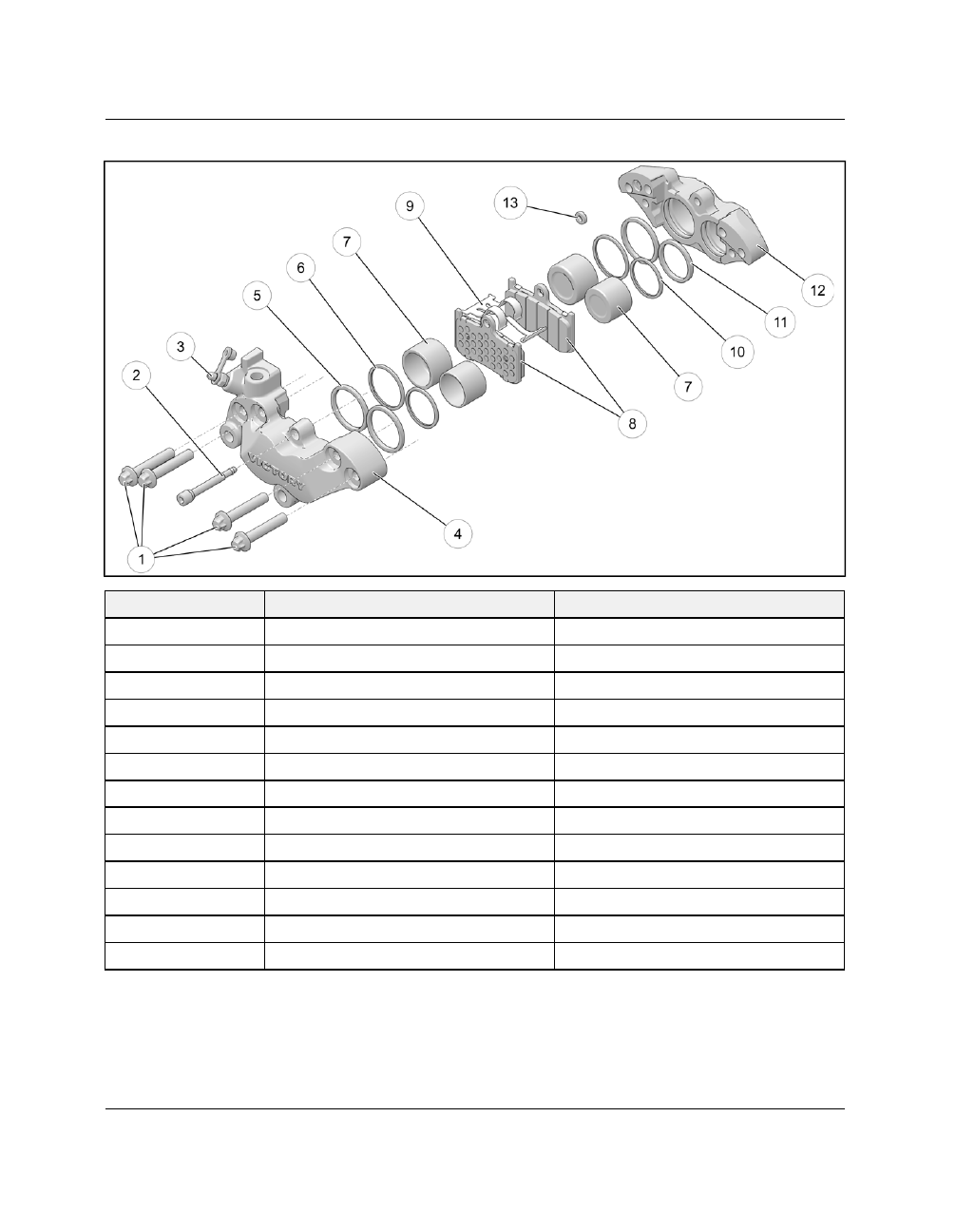
FFRROONNTT BBRRAAKKEE CCAALLIIPPEERR

NUMBER

PART DESCRIPTION

TORQUE (IF APPLICABLE)

q

Fastener, Caliper Body

20 ft-lbs (27 Nm)

w

Pad Retaining Pin

120 in-lbs (14 Nm)

e

Screw, Bleeder

48 in-lbs (5 Nm)

r

Caliper Body, Outboard

-

t

Piston Seal

-

y

Dust Seal

-

u

Piston

-

i

Brake Pads

-

o

Pad Spring

-

a

Dust Seal

-

s

Piston Seal

-

d

Caliper Body, Inboard

-

f

O-Ring, Caliper Passage

-

BRAKES

9

9.11

RREEAARR BBRRAAKKEE CCAALLIIPPEERR

NUMBER

PART DESCRIPTION

TORQUE (IF APPLICABLE)

q

Fastener, Caliper Retainer

20 ft-lbs (27 Nm)

w

Pad Retaining Pin

120 in-lbs (14 Nm)

e

Caliper Body

-

r

Guide Pin

-

t

Piston Seal

-

y

Dust Seal

-

u

Piston

-

i

Brake Pad, Outboard

-

o

Pad Spring

-

a

Brake Pad, Inboard

-

s

Carrier, Caliper

-

BRAKES

9.12

9927618 R03 - 2017 Indian Motorcycle (Full-Size) Service Manual

AABBSS M

MOODDUULLEE

BRAKES

9

9.13

W

WHHEEEELL SSPPEEEEDD SSEENNSSOORR,, FFRROONNTT

BRAKES

9.14

9927618 R03 - 2017 Indian Motorcycle (Full-Size) Service Manual

W

WHHEEEELL SSPPEEEEDD SSEENNSSOORR,, RREEAARR

BRAKES

9

9.15

AANNTTII--LLOOCCKK BBRRAAKKEESS SSYYSSTTEEM

M ((AABBSS)) SSEERRVVIICCEE

AABBSS SSYYSSTTEEM

M SSAAFFEETTYY PPRREECCAAUUTTIIOONNSS

Before working on an Indian Motorcycle equipped
with anti-lock brakes, review and understand all
general brake system, brake fluid, and ABS specific
precautions and system information. Do not attempt
maintenance or repair of the anti-lock brake system
without the proper tools.

WARNING

Proper brake system bleeding is extremely

important to ensure adequate lever reserve in the

system. Always perform the Brake Lever Reserve test

described in this manual after bleeding the anti-lock

brake system.

• Operating with non-recommended tires or improper

tire pressure may reduce the effectiveness of the
anti-lock brake system.

• Always install the recommended size and type of

tires specified for the vehicle.

• Always maintain the recommended tire pressure.
• Indian Motorcycle DOT 4 Brake Fluid is

recommended. Change every 10,000 miles (16,000
km) or 2 years, whichever comes first.

• The anti-lock brake system will not prevent wheel

lock-up, loss of traction, or loss of control

under all

conditions

. Always adhere to all safe motorcycle

riding practices as recommended.

• It is not unusual to leave tire marks on the road

surface during a hard braking event.

• The anti-lock braking system does not compensate

for or reduce the risk associated with:

• excessive speed
• reduced traction on rough, uneven or loose surfaces
• poor judgement

improper operation

AABBSS GGEENNEERRAALL IINNFFOORRM

MAATTIIOONN

The Anti-Lock Brake System is a safety feature
designed to prevent wheel lock-up and improve
control of the motorcycle during extreme braking
events, including:

• Panic braking
• Slick surface braking (such as wet road surfaces)
• Surface transitions (from asphalt to oily asphalt or

cobblestone, etc.)

Here are a few general points to note about ABS:

• The anti-lock brake system cannot be turned OFF.
• The ABS indicator lamp (located on the Instrument

Cluster) always illuminates when the key is in the
ON position and remains on until the anti-lock
system activates, which occurs when vehicle speed
exceeds 6 mph (10 kph).

• If the lamp is not illuminated when the key is ON,

connect Digital Wrench and perform an ABS System
inspection to determine the cause.

• When the ABS lamp is illuminated, the anti-lock

brakes will not activate, but the conventional brake
system will continue to operate normally.

• If the lamp continues to illuminate after the vehicle

speed exceeds 6 mph (10 kph), the system is not
functioning. Connect Digital Wrench and perform an
ABS System inspection to determine the cause.

• When the anti-lock brakes engage during a braking

event, the rider will feel pulsing at the brake lever
or pedal.

Continue to apply steady pressure to the

brakes for the best stopping performance

.

• The wheel speed sensor-to-pulse ring air gap is

adjustable. Shims can be added or removed to
bring the air-gap into specification. See adjustment
procedure outlined in this chapter.

• The ABS system

can

be reprogrammed.

• The ABS light is controlled via CAN BUS.
• Wheel speed sensors provide feedback for both

anti-lock brake operation and vehicle road speed.

• If fuse is open or removed, the ABS light will remain

ON after 6 mph (10 kph). ABS will not be active.
Normal (conventional) braking will be available
provided the system components (master cylinder,
lines, calipers, etc.) are in working order.

BRAKES

9.16

9927618 R03 - 2017 Indian Motorcycle (Full-Size) Service Manual

AABBSS SSYYSSTTEEM

M CCOOM

MPPOONNEENNTTSS

The following parts

function

in the same manner as the

same component in a non-ABS system, although parts
are not necessarily interchangeable. Always refer to
the appropriate ABS parts information when replacing
a component or component parts.

• Front Brake Calipers
• Rear Brake Caliper
• Front Master Cylinder
• Rear Master Cylinder
• Brake Light Switch
• Brake Lines

In addition to the brake system components listed
above, the following are exclusive to ABS equipped
vehicles:

• Wheel Speed Sensors (Front located on front left

fork leg; Rear mounted on rear caliper bracket)

• Wheel Speed Sensor Pulse Rings (Front and Rear

mounted to wheel with 3 disc fasteners)

• ABS Module Assembly
• ABS Related Wiring
• ABS Indicator Lamp

AABBSS OOVVEERRVVIIEEW

W OOFF OOPPEERRAATTIIOONN

The ABS system is active and available when vehicle
speed exceeds 6 mph (10 kph).

The system uses two independent Hall-Effect

Wheel

Speed Sensors

. One sensor is mounted to the front left

fork leg and one is mounted to the rear brake caliper
bracket. Two

Pulse Rings

are also used, one mounted

to the left front brake disc hub and one to the rear
brake disc hub, which rotate with the wheels. When
the vehicle is

in

motion,

the multiple

reluctor

segments on each pulse ring pass by the center pole
of the respective wheel speed sensor, generating an
electrical pulse signal in the sensor which is sent to
the

ABS Module

which is located in front of the rear

wheel.

The ABS Module interprets wheel speed signal pulses
to determine speed, rate-of-change, and front / rear
wheel speed differential to determine if wheel lock-up
is about to occur. When wheel lock-up is imminent
during a braking event, the ABS Module controls the
operation of solenoids and a pressure pump (located
inside the

ABS Module)

to regulate the amount of line

pressure and cycles (length of time) applied to the
caliper pistons and brake pads. This pressure / time
modulation can often be felt at the brake lever or the
brake pedal during an ABS braking event and is a
normal condition. Note that the brake fluid is not
diverted inside the module and does not “flow” in the
system any more than occurs in a conventional (non-
ABS) brake system.

If the surface coefficient changes (such as moving from
wet pavement to dry pavement) the ABS system will
recalculate (in a matter of milliseconds) and adjust
pressure output to caliper(s) as required.

In the event of a system fault, the ECM turns on the
ABS indicator lamp (via the CAN BUS) and leaves it on
even after vehicle speed exceeds 6 mph (10 kph)
activation speed.

If a system fault occurs, the light will remain on (and
ABS will not be active) until the ignition key is turned
to OFF position and back to ON.

The ABS Module Assembly is serviceable only as an
assembly. The module itself is not rebuildable.

Disconnect negative (-) battery cable from battery
before

servicing

ABS

brake

lines

or

system

components.

BRAKES

9

9.17

AABBSS TTRROOUUBBLLEE CCOODDEESS

C1022

520250

7

ABS Pulsar (front)

COG Chip

ON

C1023

520251

7

ABS Pulsar (rear)

COG Chip

ON

C1024

520252

5

ABS Solenoid (RRI)

Open / Short

ON

C1025

520253

5

ABS Solenoid (RRO)

Open / Short

ON

C1026

520254

5

ABS Solenoid (FFI)

Open/Short

ON

C1027

520255

5

ABS Solenoid (FFO)

Open/Short

ON

C1028

520256

5

ABS Solenoid (RFI)

Open/Short

ON

C1029

520257

5

ABS Solenoid (RFO)

Open/Short

ON

C1032

520258

11

ABS Actuator (front)

Wheel Lock (or VSS failure) ABS On

ON

C103A

520313

11

ABS Actuator (front)

Wheel Lock (or VSS failure) ABS Off

ON

C1033

520259

11

ABS Actuator (rear)

Wheel Lock (or VSS failure) ABS On

ON

C103B

520314

11

ABS Actuator (rear)

Wheel Lock (or VSS failure) ABS Off

ON

C0020

520260

8

ABS Motor

Motor Lock

ON

C1020

3

Off Stick

ON

C1021

4

On Stick

ON

C1034

520261

7

ABS Fail Safe Relay

On/Off Stick

ON

C1038

520262

4

ABS Source Voltage

Drop

ON

C1039

3

Raise

ON

C1040

520263

31

ABS Tire

Irregular Tire Size

ON

C1041

520264

12

ABS ECU

ECU Error

ON

C1042

520265

7

ABS Module

Incomplete Evacuation and Fill

ON

AABBSS AANNDD LLOOW

W BBAATTTTEERRYY VVOOLLTTAAGGEE

When attempting to start an engine on a bike with a weak battery (less than 12.5 volts KOEO) it is possible that
the ‘Check Engine’ light will illuminate and trouble code P106B will be stored in the ECM.

The P106B code indicates the engine is not getting a speed signal from the ABS module. This code DOES NOT
indicate the presence of a single faulty wheel speed sensor.

Possible Causes:

• Low battery voltage - particularly while engine is cranking
• CAN bus communication error between the ABS module and the ECM
• Both front and rear wheel speed sensors are faulty
• Faulty connection at ABS module
• ABS module not programmed (partial ECUID present in Digital Wrench)

When diagnosing this code, make sure the battery is fully charged and passes a load test prior to clearing and
retesting.

BRAKES

9.18

9927618 R03 - 2017 Indian Motorcycle (Full-Size) Service Manual

W

WHHEEEELL SSPPEEEEDD SSEENNSSOORR RREEPPLLAACCEEM

MEENNTT

Removal - Front

1.

Remove fastener

q

securing the Wheel Speed

Sensor to bracket.

2.

Withdraw speed sensor and remove any existing
shims.

3.

Noting their position, clip cable ties securing the
harness to the motorcycle.

4.

Locate connector and disconnect the wheel speed
sensor.

• Chief speed sensor connector is located in the

headlight nacelle.

• Chieftain / Roadmaster speed sensor connector is

located in the fairing behind the headlight
assembly.

Installation - Front

5.

Reverse procedure to install.

6.

Verify speed sensor air gap is within specification.
Perform adjustment procedure if necessary. See
Wheel Speed Sensor Air Gap Adjustment, page
9.19.

Removal - Rear

7.

Remove left hand saddlebag. Refer to Owner’s
Manual.

8.

Remove fastener

w

securing the Wheel Speed

Sensor to the bracket.

9.

Withdraw speed sensor and remove any existing
shims.

10. Noting their position, clip the cable ties securing

the speed sensor harness to the rear brake line
and remove P-clamp

e

from the left side of the

swingarm.

NOTE

The P-clamp fastener can be accessed from beneath

the motorcycle. Use a short 10 mm socket and ratchet

between the swingarm and inner fender wall.

11. Remove the battery box / ECM assembly to access

speed sensor plug, and disconnect. See Battery
Box Removal, page 10.13.

Installation - Rear

12. Reverse procedure to install.

13. Verify speed sensor air gap is within specification.

Perform adjustment procedure if necessary. See
Wheel Speed Sensor Air Gap Adjustment, page
9.19.

BRAKES

9

9.19

W

WHHEEEELL SSPPEEEEDD SSEENNSSOORR AAIIRR GGAAPP AADDJJUUSSTTM

MEENNTT

MEASUREMENT

Wheel Speed Sensor Air gap = .030” ± .010” (.75

mm ± .25 mm)

NOTE

Wheel Speed Sensor air gap is adjusted by adding

and removing shims. Shims are added to increase

gap and removed to decrease gap. No more than 3

shims (per Wheel Speed Sensor) should be used at

one time.

1.

Using a suitable feeler gauge, measure the air gap
between the ABS Pulse Ring and the Wheel Speed
Sensor.

2.

If the Wheel Speed Sensor air gap is out of
specification, proceed to step 3.

3.

Remove Wheel Speed Sensor from bracket.

4.

Withdraw the speed sensor and remove any
existing shims.

5.

Based on air gap measurement, add or remove
shims to achieve the specified air gap.

6.

Reinstall Wheel Speed Sensor and torque to
specification.

TORQUE

Wheel Speed Sensor:

96 in-lbs (11 Nm)

BRAKES

9.20

9927618 R03 - 2017 Indian Motorcycle (Full-Size) Service Manual

AABBSS M

MOODDUULLEE RREEPPLLAACCEEM

MEENNTT

NOTE

Do not disassemble the ABS module. The ABS

module is serviceable only as a sealed (pre-bled)

assembly. If ABS module has failed internally, replace

complete assembly.

WARNING

The hydraulic brake system MUST be completely

bled following removal or replacement of the ABS

module. Follow the brake bleeding procedure

outlined in this chapter after ABS module service.

Removal

1.

Disconnect the negative battery cable.

2.

Position motorcycle in an upright position with the
front wheel clamped in a wheel vise.

3.

California

Models

ONLY:

Remove

the

evaporative

emissions

charcoal

canister,

if

equipped.

See

Evaporative

Emission

Control

(California Models), page 1.48

4.

Remove the swingarm assembly. See Swingarm
Removal, page 8.63.

5.

Remove nut

q

securing P-clamp to bottom of ABS

Module bracket.

6.

Remove two starter solenoid fasteners

w

.

7.

Disconnect three multi plugs from the ABS Module.

8.

Disconnect hydraulic lines

e r

from ABS module

and cap off lines to prevent contamination.

9.

Remove fastener

t

securing ABS module to

bracket.

10. Remove ABS module.

Installation

11. Reverse procedure to install.

12. Bleed brake system as outlined in this chapter.

13. Attach Digital Wrench and check for ABS trouble

codes.

BRAKES

9.22

9927618 R03 - 2017 Indian Motorcycle (Full-Size) Service Manual

AABBSS BBRRAAKKEE SSYYSSTTEEM

M BBLLEEEEDDIINNGG

BBRRAAKKEE FFLLUUIIDD RREEPPLLAACCEEM

MEENNTT &

& BBLLEEEEDDIINNGG

PPRREECCAAUUTTIIOONNSS

WARNING

Contaminated brake discs or brake pads greatly

reduce braking performance and increase stopping

distance. Do not attempt to clean contaminated pads.

Replace them. Clean the brake disc with brake

cleaner.

WARNING

This brake system requires ethylene-glycol based

fluid (DOT 4). Do not use or mix different types of

fluid such as silicone-based or petroleum-based.

WARNING

Do not use brake fluid taken from old, used or

unsealed containers. Never reuse brake fluid. Brake

fluid can accumulate moisture, reducing it’s

performance.

WARNING

Brake fluid is poisonous. Keep brake fluid tightly

sealed and out of reach of children.

WARNING

A soft, spongy feeling in the brake lever and/or

brake pedal could indicate a hazardous condition in

the brake system. Do not operate the motorcycle

until the failure in the brake system is corrected.

WARNING

An unsafe condition exists when air is trapped in the

hydraulic brake system. Air in the brake hydraulic

system acts like a soft spring and absorbs a large

percentage of the pressure developed by the master

cylinder. Without this pressure, the braking system

cannot develop full braking force to allow for safe,

controlled stops. It is extremely important to bleed

the brakes properly after any brake system work has

been performed or when inspection reveals spongy

brakes.

Keep

these

points

in

mind

when

bleeding

hydraulic brakes:

• The master cylinder reservoirs have limited

capacities. It is easy to empty them during the
bleeding procedure. This introduces air into the
system which you are trying to purge. Watch the
reservoir closely and add fluid when necessary to
keep the level above the LOW mark and prevent air
from re-entering the system.

• Apply only light to moderate pressure to the lever or

pedal when bleeding the brake system. Extreme
pressure or rapid movement will cause a surge of
fluid through the small orifices of the brake system
when the bleeder screw is opened and could
introduce air into the system by means of cavitation.

• Small amounts of air can become trapped in the

banjo fastener fittings at the master cylinder(s) and
junction points of brake lines. These fittings can be
purged of air by following a standard bleeding
procedure at these fittings (instead of the bleed
screw on caliper) if necessary to speed the bleeding
process. This is usually only needed if system was
completely drained of fluid. Bleed each line
connection, starting with the fitting closest to the
master cylinder, working toward the caliper, and
ending with the bleed screw.

• Always torque banjo fasteners and other brake

system fasteners and components to specified
torque.

• Always install NEW genuine Indian Motorcycle

replacement parts and rubber parts upon assembly.
Apply special lubricant where indicated (included
in service kits).

BRAKES

9

9.23

AABBSS BBRRAAKKEE VVAACCUUUUM

M BBLLEEEEDDEERR

A vacuum bleeder is recommended for ABS system
bleeding and can also be used to bleed conventional
(non-ABS) brake systems. One style of bleeder is
shown below.

AABBSS FFLLUUIIDD CCHHAANNGGEE

Review

Brake

Fluid

Replacement

and

Bleeding

Precautions before working with brake fluid.

NOTE

When bleeding or flushing the system, monitor fluid

level in master cylinder reservoir constantly. DO NOT

allow fluid level to fall below the LOW level.

Use only DOT 4 brake fluid from a sealed container.

NOTE

EMPTY LINES - If system is dry or very low on fluid

due to parts replacement or disassembly, fill

reservoir and pump lever or pedal slowly through

stroke range until air bubbles no longer rise through

the fluid into the reservoir.

FLUSHING THE SYSTEM - Brake systems should be

flushed every 2 years or more often if the fluid is

discolored. To flush the system, follow normal brake

bleeding process, and pump fluid through the

system until fluid moving through the bleeder hose is

clear. Do not allow reservoir level to fall below the

LOW level or complete system bleeding will be

required.

AABBSS RREEAARR BBRRAAKKEE BBLLEEEEDDIINNGG

NOTE

The use of a vacuum bleeder is recommended. DO

NOT allow fluid level in reservoir to drop below the

LOW mark at any time during the bleeding

procedure.

Repeat entire bleed procedure at least once.

1.

Remove rubber cap from rear caliper bleed screw

q

and place a box end wrench on the screw.

2.

Attach a tight-fitting clear hose from the vacuum
bleeder to the bleed screw and apply vacuum.

3.

Fill rear brake fluid reservoir and leave cover off
so fluid can be added as it is drawn through the
system.

4.

Open bleed screw about 1/4 turn.

5.

Pump brake pedal repeatedly with smooth full
strokes while adding brake fluid to the reservoir as
required. For best results pump the pedal at a
fairly rapid rate but avoid pumping too fast or fluid
may become aerated. After about 2 cups of fluid
have been run through the system, the bleeder
hose should have clear, bubble-free fluid running
through it.

6.

Close bleeder screw and fill the brake fluid
reservoir.

7.

Repeat the entire bleeding process

to be sure all air

is purged from the system.

8.

Torque all bleed screws to specification and install
the rubber caps.

TORQUE

Caliper Bleeder Screws:

48 in-lbs (5 Nm)

9.

After completing the bleeding procedure a second
time,

inspect

brake

fluid

level

and

add

if

necessary.

BRAKES

9.24

9927618 R03 - 2017 Indian Motorcycle (Full-Size) Service Manual

10. Clean

the

reservoir

cover,

diaphragm,

and

reservoir

sealing

surface.

If

diaphragm

is

extended, return it to normal (flat) position. Install
diaphragm and cover.

11. If pedal is not firm, repeat bleeding procedure and

insect brake system.

AABBSS FFRROONNTT BBRRAAKKEE BBLLEEEEDDIINNGG

NOTE

Bleed left front caliper first then right caliper.

Repeat the bleeding procedure at least once.

1.

Pull

brake

lever

forward

and

rotate

reach

adjustment dial

q

to the longest reach setting to

maximize lever stroke for bleeding.

2.

Remove front brake fluid reservoir cover

w

and

leave it off so fluid can be added as it is drawn
through the system.

3.

Remove rubber cap from bleeder screw

e

on

front

left

caliper and place a box end wrench on the

screw.

4.

Attach tight fitting clear hose from vacuum
bleeder to bleed screw and apply vacuum.

5.

Hold lever to handlebar or hold firm pressure on
lever, then open bleed screw about 1/4 turn.

6.

Pump brake lever repeatedly with smooth full
strokes while adding brake fluid to the reservoir as
required. For best results pump the lever at a fairly
rapid rate but avoid pumping too fast or fluid may
become aerated. After about 2 cups of fluid have
been run through the system, the bleeder hose
should have clear, bubble-free fluid running
through it.

7.

Close bleeder screw and fill the brake fluid
reservoir.

8.

Proceed to Step 9 to bleed the right front brake
caliper.

9.

Remove rubber cap from bleeder screw on

front

right

caliper and place a box end wrench on the

screw.

10. Connect vacuum bleeder hose to the bleed screw

and start vacuum.

11. Hold lever to handlebar or hold firm pressure on

lever, then open bleed screw about 1/4 turn.

12. Pump brake lever repeatedly with smooth full

strokes while adding brake fluid to the reservoir as
required. For best results pump the lever at a fairly
rapid rate but avoid pumping too fast or fluid may
become aerated. After about 2 cups of fluid have
been run through the system, the bleeder hose
should have clear, bubble-free fluid running
through it.

13. Close bleed screw.

BRAKES

9

9.25

14. Once both front calipers have been bled, repeat

procedure again on left caliper, then right to
ensure all air has been purged.

15. Fill fluid reservoir and install diaphragm and

cover. Torque cover fasteners to specification.

TORQUE

Front Master Cylinder Cover:

14 in-lbs (2 Nm)

16. Perform Brake Lever Reserve Inspection. See

Brake Lever Reserve Inspection, page 9.25.

BBRRAAKKEE LLEEVVEERR RREESSEERRVVEE IINNSSPPEECCTTIIOONN

This procedure requires use of the Brake Lever Re-
serve Tool

(PV-50104)

.

1.

Turn handlebars fully LEFT.

2.

Set front brake lever reach adjustment

q

so it is

closest to handlebar.

3.

Place grommet of Brake Lever Reserve Inspection
Tool

PV-50104

on ball end of front brake lever.

4.

Connect a scale (commercially available) with a
minimum of 25 kg / 50 lb capacity to end of tool.

5.

Keep tool centered so it does not touch hand grip.
Pull on scale to specified force.

Brake Lever Reserve Force:

37 lbs (16.8 kg)

6.

Have an assistant verify brake lever

does not

contact

hand

grip.

Clearance

must

exist

at

specified pull force as shown.

7.

If lever makes contact with hand grip or bar end,
bleed the front brake system.

8.

See troubleshooting if bleeding problems persist.

BRAKES

9.26

9927618 R03 - 2017 Indian Motorcycle (Full-Size) Service Manual

BBRRAAKKEE SSYYSSTTEEM

M SSEERRVVIICCEE

FFRROONNTT BBRRAAKKEE PPAADD RREEPPLLAACCEEM

MEENNTT

NOTE

Always replace brake pads as a set and always

replace pads in both front calipers at the same time.

1.

Remove two acorn nuts

q

and fastener

w

from

each side of the motorcycle and remove the
caliper covers

e

.

.

2.

Remove brake pad pin

q

.

3.

Remove pad spring

w

; note direction of plate

(wide legs at top) for assembly.

4.

Push each pad back by hand to gain clearance for
new pads.

NOTE

Brake fluid will be forced back into the reservoir

when pads are pushed back. Remove reservoir cover

and monitor fluid level, or attach a hose to the brake

bleeder screw and open the bleed screw while

pushing the pads and pistons back.

5.

Remove each pad.

6.

Wipe brake disc clean with a shop towel sprayed
with brake cleaner (commercially available).

7.

Inspect caliper piston seals for any sign of fluid
leakage.

8.

Install isolator on new brake pads. Be sure isolator
plate does not protrude from the brake backing
plate.

9.

Install new brake pads with friction material
toward disc. Apply silicone grease to O-ring on
pad retaining pin.

10. Insert pin through caliper and through outer pad.

Lay spring in place over pads and press on center
while sliding pin through spring and then through
inner pad.

11. Torque pad retaining pin to specification.

TORQUE

Pad Retaining Pin:

120 in-lbs (14 Nm)

12. Inspect brake fluid in reservoir and set to proper

level.

BRAKES


Content      ..     30      31      32      33     ..