Indian motorcycle 2017. Service Manual - page 31
8.93
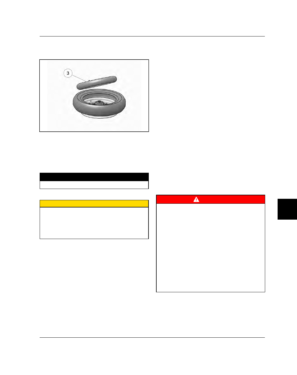
8.
Install the tube
e
into the tire starting at the valve
stem and working around until the entire tube is
laying inside the tire in a natural position.
9.
Arrange the tube, if necessary, to remove kinks or
bends, making sure that the valve stem projects
straight out and forms a 90 degree angle with the
rim.
10. Thread the valve stem lock nut until it fully draws
the valve stem through the rim and torque to
specification.
TORQUE
Valve Stem Lock Nut:
13 in-lbs (2 Nm)
11. For tube type tires, also observe the following:
CAUTION
Make sure your tire irons are smooth and free of
scratches or any sharp edges. Polish them if
necessary. Do not slide the tire iron in any more than
is necessary. When installing tube type tires, avoid
lifting the tire iron past vertical to minimize the
chance of pinching the tube.
12. Install valve core if it was removed.
13. Line up balance dot.
14. Confirm that the directional arrows are pointing in
the correct direction.
15. Inflate tire observing the precautions listed below.
Tire Inflation & Precautions
• Wear approved eye protection
• Lubricate the tire beads with a tire mounting
lubricant before inflation.
• Lock assembly on mounting machine or place in
safety cage before inflating to seat beads
• Use extension gauge and hose with slip-on air
chuck.
• Stand back with no part of your body within the
perimeter of the assembled tire and rim.
• Inflate with core in valve stem
• Never inflate above 42 psi to seat beads
• If beads do not seat by 42 psi. Deflate and repeat
procedures. Never use a volatile substance or
rubber “donut” to aid bead seating.
16. Inspect the line molded onto the tire side walls. It
must be the same distance from the rim all the way
around the tire. If the distance varies it indicates
that tire is not seated properly.
17. If tire is not seated correctly, deflate and unseat
the tire, lubricate the tire beads and repeat
inflation procedure.
18. Install wheel assembly onto balance stand and
spin. Observe the wheel assembly while it is
spinning to make sure the tire is seated properly.
19. Adjust tire pressures to specifications.
20. Balance tire / wheel assembly.
WARNING
FOR REPAIRED TIRES
: Speed should not exceed
50 MPH for the first 24 hours after repair and
repaired tire should never be used over 80 MPH.
Inspect inflation pressure after tire cools for at least
three hours following run-in.
FOR NEW TIRES
: Replacement of OEM tires or
replacement with differently constructed tires will
not immediately produce improved reactions the
same as the original tires when new. When new tires
are installed, they should not be subjected to
maximum power or hard cornering until a reasonable
“scrub” period of approximately 100 miles has been
covered. This will permit the rider to become
accustomed to “feel” of new tires or tire
combination, and achieve optimum road grip.
Inspect and adjust tire inflation pressure after tire
cools down for at least three hours following “run-
in”.