Indian motorcycle 2017. Service Manual - page 30
 

  Главная      Manuals     Indian motorcycle 2017. Service Manual


Search            copyright infringement  


Content      ..     28      29      30      31     ..


Indian motorcycle 2017. Service Manual - page 30


8

8.77

TTPPM

MSS AACCTTIIVVAATTIIOONN ((SSPPRRIINNGGFFIIEELLDD))

TPMS sensor activation is required any time the
following occur:

• TPMS sensor has been replaced.
• Vehicle Control Module (VCM) has been reflashed.
• Vehicle Control Module (VCM) has been replaced.

TPMS activation or “Wake Up” requires the use of
the TPMS Activation tool (PF-51288).

NOTE

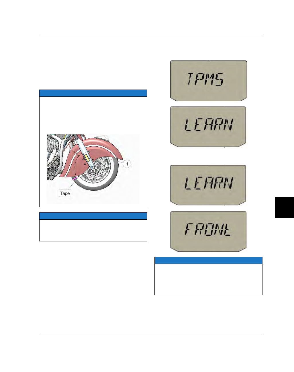
The TPMS sensor is located 180° from the valve stem

q

. Locate the position of the front and rear valve

stems and place a piece of tape on the tire on the

opposite side (180°). Both pieces of tape (front and
rear tires) should be visible so the TPMS Activation

tool can be held within 3 in (7.6 cm) of the tire where

the sensor is located.

NOTE

The TPMS Activation tool should be held close to the

sidewall of the tire

when activating the sensors. If

the Activation tool is held over the aluminum rim, the

sensor signal may not be received.

1. Press the power button to power up the motorcycle

electrical system.

2. Press

and

hold

RH

and

LH

mode

buttons

simultaneously until the TMPS LEARN screens
toggle on the screen.

3. Press the LH mode button to begin the activation

process. The following screens should toggle.

NOTE

Once TPMS setup has been initiated on the

motorcycle, there is approximately 30 seconds to

complete the activation procedure before the

system times out and must be restarted. Make

sure the TPMS Activation tool is close at hand and

powered up before initiating setup.

STEERING / SUSPENSION

8.78

9927618 R03 - 2017 Indian Motorcycle (Full-Size) Service Manual

4. With

the

Activation

tool

powered

up

and

“Searching” for the TPMS sensor, hold the device
no more than 3 in (7.6 cm) from the sidewall where
the tape was placed on the front tire. You should
hear a short audible “beep” acknowledging sensor
activation. A value will appear on the screen
indicating the successful reading of the front wheel.
The display will switch to the rear wheel.

5. Move to the rear wheel and hold the Activation tool

no more than 3 in (7.6 cm) from the sidewall where
the tape was placed previously. You should hear a
short

audible

“beep”

acknowledging

sensor

activation. A value will appear on the screen
indicating the successful reading of the rear wheel.
The

following

screens

will

toggle

indicating

successful activation of both TPMS sensors.

STEERING / SUSPENSION

8

8.79

TTPPM

MSS AACCTTIIVVAATTIIOONN ((CCHHIIEEFFTTAAIINN DDAARRKK HHOORRSSEE))

TPMS sensor activation is required any time the
following occur:

• TPMS sensor has been replaced.
• Vehicle Control Module (VCM) has been reflashed.
• Vehicle Control Module (VCM) has been replaced.

TPMS activation or “Wake Up” requires the use of
the TPMS Activation tool (PF-51288).

NOTE

The TPMS sensor is located 180° from the valve stem

q

. Locate the position of the front and rear valve

stems and place a piece of tape on the tire on the

opposite side (180°). Both pieces of tape (front and
rear tires) should be visible so the TPMS Activation

tool can be held within 3 in (7.6 cm) of the tire where

the sensor is located.

NOTE

The TPMS Activation tool should be held close to the

sidewall of the tire

when activating the sensors. If

the Activation tool is held over the aluminum rim, the

sensor signal may not be received.

1. Press the power button to power up the motorcycle

electrical system.

2. Press

and

hold

RH

and

LH

mode

buttons

simultaneously until the SETUP screen is displayed
on the MFD.

3. Press

the

RH

mode

button

until

TPMS

is

highlighted.

STEERING / SUSPENSION

8.80

9927618 R03 - 2017 Indian Motorcycle (Full-Size) Service Manual

4. Press the LH mode button to begin the activation

process. The following screen should appear.

NOTE

Once TPMS setup has been initiated on the

motorcycle, there is approximately 30 seconds to

complete the activation procedure before the

system times out and must be restarted. Make

sure the TPMS Activation tool is close at hand and

powered up before initiating setup.

5. After a few seconds the following screen will

appear, indicating that the TPMS sensors are ready
to be activated with the Activation tool.

6. With

the

Activation

tool

powered

up

and

“Searching” for the TPMS sensor, hold the device
no more than 3 in (7.6 cm) from the sidewall where
the tape was placed on the front tire. You should
hear a short audible “beep” acknowledging sensor
activation. The MFD will switch to the rear wheel.

7. Move to the rear wheel and hold the Activation tool

no more than 3 in (7.6 cm) from the sidewall where
the tape was placed previously. You should hear a
short

audible

“beep”

acknowledging

sensor

activation. The MFD will display the following
screen indicating successful activation of both
TPMS sensors.

STEERING / SUSPENSION

8

8.81

TTPPM

MSS AACCTTIIVVAATTIIOONN ((CCHHIIEEFFTTAAIINN // RROOAADDM

MAASSTTEERR))

TPMS sensor activation is required any time the
following occur:

• TPMS sensor has been replaced.
• Vehicle Control Module (VCM) has been reflashed.
• Vehicle Control Module (VCM) has been replaced.

TPMS activation or “Wake Up” requires the use of
the TPMS Activation tool (PF-51288).

NOTE

The TPMS sensor is located 180° from the valve stem

q

. Locate the position of the front and rear valve

stems and place a piece of tape on the tire on the

opposite side (180°). Both pieces of tape (front and
rear tires) should be visible so the TPMS Activation

tool can be held within 3 in (7.6 cm) of the tire where

the sensor is located.

NOTE

The TPMS Activation tool should be held close to the

sidewall of the tire

when activating the sensors. If

the Activation tool is held over the aluminum rim, the

sensor signal may not be received.

1. Press the power button to power up the motorcycle

electrical system.

2. Press the middle dropdown button on top of screen

to open the settings menu.

3. Press the “SETTINGS” icon in the upper right hand

corner.

4. Press the “TPMS Learn” arrow button.

NOTE

Once TPMS setup has been initiated on the

motorcycle, there is approximately 30 seconds to

complete the activation procedure before the

system times out and must be restarted. Make

sure the TPMS Activation tool is close at hand and

powered up before initiating setup.

STEERING / SUSPENSION

8.82

9927618 R03 - 2017 Indian Motorcycle (Full-Size) Service Manual

5. Press the “Vehicle” icon on the left hand side of

screen. This screen indicates that the TPMS sensors
are ready to be activated with the Activation tool.
Press the green check to start the TPMS learn
procedure.

6. With

the

Activation

tool

powered

up

and

“Searching” for the TPMS sensor, hold the device
no more than 3 in (7.6 cm) from the sidewall where
the tape was placed on the front tire. You should
hear a short audible “beep” acknowledging sensor
activation. The display will switch to the rear
wheel.

7. Move to the rear wheel and hold the Activation tool

no more than 3 in (7.6 cm) from the sidewall where
the tape was placed previously. You should hear a
short

audible

“beep”

acknowledging

sensor

activation. The

screen will display a screen

indicating successful activation of both TPMS
sensors.

STEERING / SUSPENSION

8

8.83

TTIIRREE CCHHAANNGGIINNGG,, GGEENNEERRAALL IINNFFOORRM

MAATTIIOONN

There are three generally acceptable methods to
dismount and mount a motorcycle tire to its rim. For
each of the three methods, there are countless
variations.

The three general methods are:

• Pneumatic or electrically operated tire machine
• Manually operated tire machine
• Manual manipulation of tire irons

Indian Motorcycle permits and recommends all three
of the general methods, but realizes that careless or
improper work habits can damage both the tire and
rim no matter which method is used. With any of the
methods, care must still be taken to avoid damaging
the rim, tire, inner tube (if applicable), brake disk, or
sprocket.

The pneumatic or electrically operated tire machine is
preferred because it is the most efficient method to
dismount and mount tires.

The manually operated tire machine is the next
preferred method. It can be just as efficient as a power
assisted tire machine but with some of the machines it
may be necessary to remove the belt driven sprocket
in order to gain sufficient clearance for tire removal.

Manual manipulation is the least preferred method
since it will generally not deliver the same efficiency
as the other methods and greater care needs to be
taken when performed. Care must be taken when
using tire irons to not damage or stress the tire bead,
Also, the opposite bead needs to be in drop center of
wheel during mounting and dismounting of the tire.

Be very careful not to damage the rim, tire, inner tube,
brake disk, TPMS sensor or sprocket regardless of
which method is used.

CAUTION

On models equipped with a Tire Pressure Monitoring

System (TPMS) break beads at the valve stem, then at

90

°

and 270

°

from the valve stem as required. If the

bead is broken 180

°

from the valve stem (sensor

location) the TPMS sensor may be damaged and

require replacement. See TPMS Overview, page 8.76.

STEERING / SUSPENSION

8.84

9927618 R03 - 2017 Indian Motorcycle (Full-Size) Service Manual

TTIIRREE RREEM

MOOVVAALL

TTIIRREE RREEM

MOOVVAALL -- ((CCHHIIEEFFTTAAIINN // RROOAADDM

MAASSTTEERR))

NOTE

This procedure is written assuming that a

pneumatic, electric, or manually operated rim-

clamp type tire machine is being used.

1.

Remove wheel / tire assembly from motorcycle.
See Steering / Suspension chapter for front and
rear wheel removal procedures.

2.

Remove valve core

q

from valve stem and let all

air escape.

3.

CAUTION

The TPMS sensor is located 180

°

from the valve stem.

If the bead is broken 180

°

from the valve stem the

TPMS sensor may be damaged and require

replacement.

Mount the wheel assembly onto a tire bead
breaker and break the bead starting at the valve
stem, then again at 90° and again at 270° from the
valve stem as necessary.

4.

Flip the wheel assembly over and repeat STEP 3 on
the other side.

CAUTION

IMPORTANT

: Take great care not to bend or

otherwise damage the brake disc and/or belt driven

sprocket. If the bead breaker being used interferes

with either the brake disk and/or belt driven

sprocket, remove the disc or sprocket as required.

5.

Push tire down and lubricate tire bead with tire
lubricant on both sides of the tire.

6.

NOTE

Refer to manufacturer’s instructions for proper

tire changer operation.

Mount the tire and wheel assembly on the tire
machine per the manufacturers instructions.

7.

Carefully work around the circumference of the
upper bead

w

with the tire lever until it is

completely off of the rim.

STEERING / SUSPENSION

8

8.85

8.

Paying attention to the location of the TPMS sensor

e

, lift the lower tire bead up until the tire lever can

be positioned and the tire completely removed.

9.

Work around the circumference of the rim until the
tire can be lifted free of the rim.

TTIIRREE RREEM

MOOVVAALL -- ((CCLLAASSSSIICC // VVIINNTTAAGGEE))

NOTE

This procedure is written assuming that a

pneumatic, electric, or manually operated rim-

clamp type tire machine is being used.

1.

Remove wheel / tire assembly from motorcycle.
See Steering / Suspension chapter for front and
rear wheel removal procedures.

2.

Remove valve core

q

from valve stem and let all

air escape.

3.

Mount the wheel assembly onto a tire bead
breaker and break the bead starting at the valve
stem and continue around the circumference of the
rim as necessary.

4.

Flip the wheel assembly over and repeat STEP 3 on
the other side.

CAUTION

IMPORTANT

: Take great care not to bend or

otherwise damage the brake disc and/or belt driven

sprocket. If the bead breaker being used interferes

with either the brake disk and/or belt driven

sprocket, remove the disc or sprocket as required.

5.

NOTE

Refer to manufacturer’s instructions for proper

tire changer operation.

Mount the tire and wheel assembly on the tire
machine per the manufacturers instructions.

STEERING / SUSPENSION

8.86

9927618 R03 - 2017 Indian Motorcycle (Full-Size) Service Manual

6.

Carefully work around the circumference of the
upper bead

w

with the tire lever until it is

completely off of the rim.

7.

Lift the lower tire bead up until the inner tube can
be withdrawn from the tire. Remove inner tube

e

.

8.

Lift the lower tire bead up until the tire lever can
be positioned and the tire completely removed.

9.

Work around the circumference of the rim until the
tire can be lifted free of the rim.

TTIIRREE RREEM

MOOVVAALL -- ((DDAARRKK HHOORRSSEE))

NOTE

This procedure is written assuming that a

pneumatic, electric, or manually operated rim-

clamp type tire machine is being used.

1. Remove wheel / tire assembly from motorcycle.

See Steering / Suspension chapter for front and
rear wheel removal procedures.

2. Remove valve core

q

from valve stem and let all

air escape.

3. Mount the wheel assembly onto a tire bead breaker

and break the bead starting at the valve stem and
continue around the circumference of the rim as
necessary.

4. Flip the wheel assembly over and repeat STEP 3 on

the other side.

CAUTION

IMPORTANT

: Take great care not to bend or

otherwise damage the brake disc and/or belt driven

sprocket. If the bead breaker being used interferes

with either the brake disk and/or belt driven

sprocket, remove the disc or sprocket as required.

5.

NOTE

Refer to manufacturer’s instructions for proper

tire changer operation.

Mount the tire and wheel assembly on the tire
machine per the manufacturers instructions.

STEERING / SUSPENSION

8

8.87

6. Carefully work around the circumference of the

upper bead

w

with the tire lever until it is

completely off of the rim.

7. Lift the lower tire bead up until the tire lever can be

positioned and the tire completely removed.

8. Work around the circumference of the rim until the

tire can be lifted free of the rim.

STEERING / SUSPENSION

8.88

9927618 R03 - 2017 Indian Motorcycle (Full-Size) Service Manual

W

WHHEEEELL IINNSSPPEECCTTIIOONN

VVIISSUUAALL IINNSSPPEECCTTIIOONN &

& RRUUNNOOUUTT

1.

Clean

the

rim

of

all

rubber

particles

and

corrosion.

2.

Inspect wheel for cracks and/or distortion.

3.

Inspect bead seating area for scratches, distortion,
or damage that could prevent proper sealing.

4.

Measure wheel for radial runout (1).

5.

Measure wheel for axial runout (2).

NOTE

Measure runout on tire bead sealing surface of

wheel. Be sure surface is clean.

6.

Compare measurements of axial and radial runout
to specifications. See Service Specifications, page
8.40. 
Replace wheel if any measurement exceeds
Service Limit.

7.

Clean the sealing surfaces of the rim thoroughly.
Use a soft brush (nylon) soap and water if
necessary.

WARNING

Do not scratch or damage sealing surfaces of rim.

Loss of air pressure can cause a loss of control and an

accident, resulting in serious injury or death.

TTIIRREE RREEPPAAIIRR PPRREECCAAUUTTIIOONNSS

WARNING

Only permanent plug-patch repairs of small tread

area punctures from

inside

the dismounted tire are

recommended. Never perform an exterior repair and

never use an inner tube as a substitute for a proper

repair. Speed should not exceed 50 MPH for the first

24 hours after repair and the repaired tire should

never be used over 80 MPH. Inspect inflation

pressure after tire cools for at least three hours

following initial operation.

STEERING / SUSPENSION

8

8.89

VVAALLVVEE SSTTEEM

M

VVAALLVVEE SSTTEEM

M IINNSSPPEECCTTIIOONN

1.

Remove the valve stem cap and spray the valve
stem down with a mild soap and water solution.

2.

Observe the area around the base of the valve
stem and valve core area. If any bubbles form over
a 1–2 minute period, the valve stem or inner tube
should be replaced.

3.

Inspect valve stem for cracks or visible damage
and replace if necessary.

NOTE

Tubeless

: Valve stem replacement is recommended

when tire is being replaced.

Tube Type

: Inner tube replacement is

recommended when tire is being replaced.

VVAALLVVEE SSTTEEM

M IINNSSTTAALLLLAATTIIOONN -- RRUUBBBBEERR

1.

Remove tire from wheel and cut valve stem with a
diagonal cutter to remove.

2.

Clean tire valve hole and sealing area thoroughly.

3.

Lubricate tire valve and hole with P-80 rubber
lubricant or equivalent.

4.

Place tire valve into hole and fastener a tire valve
installation tool (commercially available) onto
valve.

5.

Place a small wood block against the rim to
improve leverage point and keep the pulling angle
as straight as possible. (Fig. 9)

6.

Pull the valve until fully seated and remove tool.

VVAALLVVEE SSTTEEM

M IINNSSTTAALLLLAATTIIOONN -- M

MEETTAALL

IMPORTANT

The Chieftain, Roadmaster and Dark Horse models

use directional tires and wheels. Pay close attention

to markings to ensure proper tire and valve stem

orientation.

1. Remove tire from wheel as outlined in this chapter.

2. Remove valve stem nut

q

, valve stem

w

and o-

ring

e

.

3. Clean gasket or o-ring sealing surface of rim.

4. Place new valve stem (with seal washer or O-ring

installed) through hole in rim and position it so the
stem is perpendicular from wheel center and,
valve opening facing away from surface containing
direction indicator.

5. Hold stem and tighten nut to specification.

TORQUE

Valve Stem Nut:

44 in-lbs (5 Nm)

6. Install tire as outlined in this chapter.

STEERING / SUSPENSION

8.90

9927618 R03 - 2017 Indian Motorcycle (Full-Size) Service Manual

TTIIRREE IINNSSTTAALLLLAATTIIOONN

TTIIRREE IINNSSTTAALLLLAATTIIOONN -- ((CCHHIIEEFFTTAAIINN // RROOAADDM

MAASSTTEERR))

NOTE

This procedure is written assuming that a

pneumatic, electric, or manually operated rim-

clamp type tire machine is being used.

NOTE

Balance Dots

Dunlop tires have a yellow dot on the sidewall which

corresponds to the lightest part of the tire. This dot is

meant to line-up with the tire valve which often is the

heaviest part of the rim (although this is not always

the case).

Indian Motorcycle does not recommend the use of

liquid balancer/sealers. These are a form of

temporary repair which may adversely affect ply

material and mask secondary damage caused by the

penetrating object. Reliance upon sealants can result

in sudden tire failure and accident.

Directional Arrows

Tires

q

and

rims

w

have directional arrows that must

be observed when installing tires to rims.

The wheel assemblies must be free of foreign debris

that would affect balancing.

Carefully inspect the wheel bearings, seals and axle

for damage or corrosion.

1.

Lubricate both tire beads with rubber lubricant.

WARNING

Never apply grease, oil, gasoline, spray type

lubricants or anything other than rubber lubricant or

a neutral soap and water solution to the tire bead.

Doing so can damage the tire.

2.

NOTE

Refer to manufacturer’s instructions for proper

tire changer operation.

Mount the tire and wheel assembly on the tire
machine per the manufacturers instructions.

3.

Orient tire correctly as to the balance dot and
directional arrows.

4.

CAUTION

Use care not to damage the TPMS sensor while

installing the tire bead over the edge of the rim.

Push tire on to rim until one bead is installed. It
shouldn’t be necessary to use tire irons to put one
side of the tire onto the rim. Remember to keep
bead(s) in the drop center of the wheel whenever
possible.

NOTE

Confirm tire is positioned correctly by observing

directional arrows.

5.

Lubricate the tire bead.

6.

With your hands, push as much of the remaining
tire bead as possible into the rim, pinching both
upper and lower beads into the drop center.

7.

When no more of tire can be installed by hand,
press down on portion of tire in front of you with
your knee to keep the top bead in the drop center.

STEERING / SUSPENSION

8

8.91

8.

Install

the

tire

lever and

work

around

the

remaining circumference of the wheel until the
bead is fully installed onto the rim.

NOTE

Be sure both beads are forced as far as possible into

the drop center of the rim.

9.

Install valve core if it was removed.

10. Line up balance dot.

11. Confirm that the directional arrows are pointing in

the correct direction.

12. Bounce tire on the floor several times while

rotating tire. This will expand tire bead outward
slightly which will make tire inflation easier.

13. Inflate tire observing the precautions listed below.

Tire Inflation & Precautions

• Wear approved eye protection
• Lubricate the tire beads with a tire mounting

lubricant before inflation.

• Lock assembly on mounting machine or place in

safety cage before inflating to seat beads

• Use extension gauge and hose with slip-on air

chuck.

• Stand back with no part of your body within the

perimeter of the assembled tire and rim.

• Inflate with core in valve stem
• Never inflate above 42 psi to seat beads
• If beads do not seat by 42 psi. Deflate and repeat

procedures. Never use a volatile substance or
rubber “donut” to aid bead seating.

14. Inspect the line molded onto the tire side walls. It

must be the same distance from the rim all the way
around the tire. If the distance varies it indicates
that tire is not seated properly.

15. If tire is not seated correctly, deflate and unseat

the tire, lubricate the tire beads and repeat
inflation procedure.

16. Install wheel assembly onto balance stand and

spin. Observe the wheel assembly while it is
spinning to make sure the tire is seated properly.

17. Adjust tire pressures to specifications.

18. Balance tire / wheel assembly.

WARNING

FOR REPAIRED TIRES

: Speed should not exceed

50 MPH for the first 24 hours after repair and

repaired tire should never be used over 80 MPH.

Inspect inflation pressure after tire cools for at least

three hours following run-in.

FOR NEW TIRES

: Replacement of OEM tires or

replacement with differently constructed tires will

not immediately produce improved reactions the

same as the original tires when new. When new tires

are installed, they should not be subjected to

maximum power or hard cornering until a reasonable

“scrub” period of approximately 100 miles has been

covered. This will permit the rider to become

accustomed to “feel” of new tires or tire

combination, and achieve optimum road grip.

Inspect and adjust tire inflation pressure after tire

cools down for at least three hours following “run-

in”.

STEERING / SUSPENSION

8.92

9927618 R03 - 2017 Indian Motorcycle (Full-Size) Service Manual

TTIIRREE IINNSSTTAALLLLAATTIIOONN -- ((CCLLAASSSSIICC // VVIINNTTAAGGEE))

NOTE

This procedure is written assuming that a

pneumatic, electric, or manually operated rim-

clamp type tire machine is being used.

NOTE

Balance Dots

Dunlop tires have a yellow dot on the sidewall which

corresponds to the lightest part of the tire. This dot is

meant to line-up with the tire valve which often is the

heaviest part of the rim (although this is not always

the case).

Indian Motorcycle does not recommend the use of

liquid balancer/sealers. These are a form of

temporary repair which may adversely affect ply

material and mask secondary damage caused by the

penetrating object. Reliance upon sealants can result

in sudden tire failure and accident.

Directional Arrows

Tires

and

rims have directional indicators that must

be observed when installing tires to rims.

Rims:

The valve stem

q

should exit the rim on the

riders RH side when installed on the motorcycle.

Tires:

The tires

w

have directional arrows located on

the side wall.

The wheel assemblies must be free of foreign debris

that would affect balancing.

Carefully inspect the wheel bearings, seals and axle

for damage or corrosion.

1.

Make sure that the edges of the rim, where the
beads rest, are clean and free of debris.

2.

Lubricate both tire beads with rubber lubricant.

CAUTION

Never apply grease, oil, gasoline, spray type

lubricants or anything other than rubber lubricant or

a neutral soap and water solution to the tire bead.

Doing so can damage the tire.

3.

NOTE

Refer to manufacturer’s instructions for proper

tire changer operation.

Mount the tire and wheel assembly on the tire
machine per the manufacturers instructions.

4.

Orient tire correctly as to the balance dot and
directional indicators.

5.

Push tire on to rim until one bead is installed. It
shouldn’t be necessary to use tire irons to put one
side of the tire onto the rim. Remember to keep
bead(s) in the drop center of the wheel whenever
possible.

NOTE

Confirm tire is positioned correctly by observing

directional arrow.

6.

Thread valve stem base nut completely on to valve
stem.

7.

Apply baby powder to new (deflated) tube and
install by inserting valve stem through the rim
band and rim.

STEERING / SUSPENSION


Content      ..     28      29      30      31     ..