Indian motorcycle 2017. Service Manual - page 28


  Главная      Manuals     Indian motorcycle 2017. Service Manual


Search            copyright infringement  


Content      ..     26      27      28      29     ..


Indian motorcycle 2017. Service Manual - page 28


8

8.45

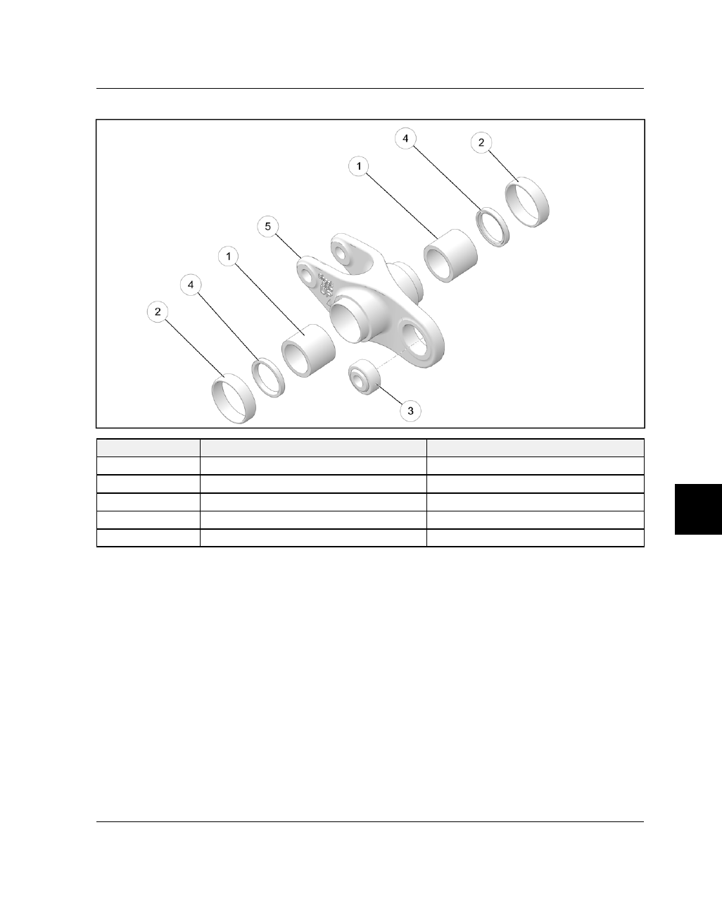
RROOCCKKEERR AASSSSEEM

MBBLLYY

NUMBER

PART DESCRIPTION

TORQUE (IF APPLICABLE)

q

Bearing, Needle

-

w

Bearing, Thrust

-

e

Spherical Bearing

-

r

Seal

-

t

Rocker

-

STEERING / SUSPENSION

8.46

9927618 R03 - 2017 Indian Motorcycle (Full-Size) Service Manual

SSW

WIINNGGAARRM

M

NUMBER

PART DESCRIPTION

TORQUE (IF APPLICABLE)

q

Nut, Swingarm — M18 x 1.5 (QTY.1)

65 ft-lbs (88 Nm)

w

Spacer, Pivot (LH Outer)

-

e

Spacer, Pivot (LH)

-

r

Retaining Ring

-

t

Ball Bearing — M42 x 20 x 12 (QTY.2)

-

y

Swingarm

-

u

Seal

-

i

Bearing, Needle

-

o

Suspension Pivot

-

a

Nut, Jamb — M27 x 1.5 (QTY.1)

75 ft-lbs (102 Nm)

s

Fastener, Belt Guard — M6 x 1.0 x 20 (QTY.2)

96 in-lbs (11 Nm)

d

Sleeve

-

f

Guard, Lower Belt

-

g

Axle, Rear

-

h

Nut, Axle Adjuster

-

j

Axle Adjuster

-

k

Spacer, RH

-

l

Adjuster Plate, LH

-

1(

Nut, Axle — M18 x 1.5 (QTY.1)

Step 1: 15 ft-lbs (20 Nm)

Step 2: 65 ft-lbs (88 Nm)

STEERING / SUSPENSION

8

8.47

DDRRIIVVEE BBEELLTT SSEERRVVIICCEE

DDRRIIVVEE BBEELLTT IINNSSPPEECCTTIIOONN

1.

Inspect belt tension and adjust if necessary. See
Drive Belt Inspection, page 2.27.

2.

If one or more component is damaged, replace
belt and both sprockets as a set if the drive system
has been in service for 5000 miles or more (8000
Km).

DDRRIIVVEE BBEELLTT RREEM

MOOVVAALL

NOTE

If belt is to be reinstalled, mark direction of rotation

on the outer surface of belt. Reinstall belt in same

direction as it was removed.

WARNING

A misaligned rear axle can cause drive line noise and

damage the drive belt, which could cause belt failure

and loss of control of the motorcycle.

WARNING

Care should be taken to be sure the motorcycle will
not tip or fall while elevated. Severe personal injury

or death may occur if the motorcycle tips or falls.

1.

Remove rear wheel. See Rear Wheel Removal /
Installation, page 8.56.

2.

Remove

swingarm

assembly.

See

Swingarm

Removal, page 8.63.

3.

Remove exhaust assembly. See Muffler Removal,
page 3.87.

4.

Remove drive sprocket cover. See Drive Sprocket
Cover, Removal / Installation, page 8.48.

5.

Remove belt from drive sprocket.

DDRRIIVVEE BBEELLTT IINNSSTTAALLLLAATTIIOONN

1.

Inspect sprockets and verify sprocket fasteners
are tight.

2.

Install drive belt with the Indian Motorcycle script
situated so that it reads correctly when viewed
from the RH side of the motorcycle.

3.

Install

the

drive

sprocket

cover.

See

Drive

Sprocket Cover, Removal / Installation, page 8.48.

4.

Install

the

exhaust

system.

See

Head

Pipe

Installation, page 3.91.

5.

Install the swingarm assembly. See Swingarm
Installation, page 8.67.

6.

Install the rear wheel. See Rear Wheel Removal /
Installation, page 8.56.

7.

Set drive belt alignment and tension. See Drive
Belt Adjustment, page 2.31.

STEERING / SUSPENSION

8.48

9927618 R03 - 2017 Indian Motorcycle (Full-Size) Service Manual

DDRRIIVVEE SSPPRROOCCKKEETT SSEERRVVIICCEE

DDRRIIVVEE SSPPRROOCCKKEETT CCOOVVEERR,, RREEM

MOOVVAALL //

IINNSSTTAALLLLAATTIIOONN

1.

Remove the rear muffler and head pipe assembly.
See Head Pipe Removal, page 3.90.

2.

Using a 5mm hex wrench, remove the two short
fasteners

q

and two long fasteners

w

securing the

cover to the engine and remove cover.

NOTE

Note the position of the oxygen sensor harness for

use during installation.

3.

To install the drive sprocket cover, reverse the
removal procedure.

4.

Torque

drive

sprocket

cover

fasteners

to

specification.

TORQUE

Drive Sprocket Cover Fasteners (All):

84 in-lbs (10

Nm)

DDRRIIVVEE SSPPRROOCCKKEETT RREEM

MOOVVAALL

This procedure requires use of the Clutch Shaft
Holding Tool (PF-51232).

1.

Place motorcycle in an upright position with the
front wheel clamped in a wheel vise.

2.

Remove exhaust system. See Muffler Removal,
page 3.87

3.

Remove the drive sprocket cover. See Drive
Sprocket Cover, Removal / Installation, page 8.48.

4.

Drain engine oil. See Engine Oil / Filter Change,
page 2.9.

5.

Remove

primary

cover.

See

Primary

Cover

Removal, page 5.7.

6.

Remove clutch assembly. See Clutch Removal,
page 5.14.

7.

Install the Clutch Shaft Holding Tool

(PF-51232)

.

8.

Loosen rear axle nut

q

so that wheel assembly can

be moved forward to slacken drive belt.

9.

Loosen both axle adjuster nuts evenly to move
wheel forward until belt is loose.

10. Pull belt off drive sprocket.

STEERING / SUSPENSION

8

8.49

11. Remove two locking plate fasteners

w

and locking

plate

e

.

12. Remove drive sprocket retaining nut

r

and drive

sprocket

t

.

13. Remove spacer

y

, and O-ring

u

from output

shaft.

STEERING / SUSPENSION

8.50

9927618 R03 - 2017 Indian Motorcycle (Full-Size) Service Manual

DDRRIIVVEE SSPPRROOCCKKEETT IINNSSPPEECCTTIIOONN

1.

Visually inspect sprocket teeth

q

for excessive

wear and damage.

2.

Inspect splines

w

for a tight fit on output shaft

splines.

3.

Inspect the back surface of sprocket hub

e

where

it contacts the seal sleeve. Replace if worn or if
surface is rough.

4.

Inspect the machined sealing surface of the spacer
sleeve

r

. Replace the spacer sleeve if it is

grooved or otherwise damaged.

5.

Sprockets and belt normally exhibit a polished
appearance

due

to

normal

operation.

Belt

replacement

is

not

required

unless

uncharacteristic damage is noted, or if the mileage
service interval is reached. Belt or sprocket
damage is usually due to debris trapped between
belt and sprocket, or from improper maintenance
and adjustment.

STEERING / SUSPENSION

8

8.51

DDRRIIVVEE SSPPRROOCCKKEETT IINNSSTTAALLLLAATTIIOONN

NOTE

If replacing the output shaft seal, it will be necessary

to use the Output Shaft Seal Tool

(PF-51243)

for

proper installation.

1.

Place new output shaft seal over the output shaft
and drive into position using the Output Shaft Seal
Tool

(PF-51243)

.

2.

Apply grease to a new O-ring

q

and install on

output shaft.

3.

Install seal sleeve

w

with the chamfer on inside

diameter of sleeve facing in, toward O-ring.

4.

Clean shaft threads and sprocket nut to remove all
previous thread locking agent.

5.

Apply a light film of anti-seize compound to
splines of shaft. Place belt onto front sprocket,
place sprocket over splines of output shaft.

6.

Apply Loctite™ 262 to threads of shaft and nut.

7.

Install

drive

sprocket

nut

and

torque

to

specification.

NOTE

Install Clutch Shaft Holding Tool

(PF-51232)

on clutch

shaft prior to tightening sprocket nut.

TORQUE

Drive Sprocket Nut:

180 ft-lbs (244 Nm)

8.

Install lock plate

e

and tighten fasteners

r

until

lightly seated on plate.

NOTE

The lock plate can be installed in many positions and

either side of the plate can be used. If the plate still

does not align, tighten sprocket nut slightly and try to

fit the lock plate again.

9.

Rotate the plate CLOCKWISE until it stops and
hold it firmly against the nut.

10. Torque lock plate fasteners to specification.

TORQUE

Lock Plate Fasteners:

88 in-lbs (10 Nm)

11. Remove the clutch shaft holding tool and install the

clutch assembly. See Clutch Installation, page
5.19.

12. Install the primary cover. See Primary Cover

Installation, page 5.12.

13. Add engine oil to correct level. See Checking

Engine Oil, page 2.10.

14. Install

the

drive

sprocket

cover.

See

Drive

Sprocket Cover, Removal / Installation, page 8.48.

15. Install

the

exhaust

system.

See

Head

Pipe

Installation, page 3.91.

16. Adjust belt tension and wheel alignment. See

Drive Belt Adjustment, page 2.31.

STEERING / SUSPENSION

8.52

9927618 R03 - 2017 Indian Motorcycle (Full-Size) Service Manual

DDRRIIVVEENN SSPPRROOCCKKEETT SSEERRVVIICCEE

DDRRIIVVEENN SSPPRROOCCKKEETT RREEM

MOOVVAALL

CAUTION

Protect brake disc surface while working on wheel.

1.

Remove rear wheel. See Rear Wheel Removal /
Installation, page 8.56.

2.

Remove the RH wheel spacer

q

from the driven

sprocket roller bearing.

3.

Lift the driven sprocket assembly

w

off of the drive

damper

e

.

DDRRIIVVEENN SSPPRROOCCKKEETT IINNSSPPEECCTTIIOONN

1.

Visually inspect sprocket teeth

q

for excessive

wear and damage from foreign material or road
debris.

2.

Inspect the back side of the sprocket where it
engages the damper

w

for wear, galling or

roughness. Surface must be smooth, with no burrs
or surface irregularities.

STEERING / SUSPENSION

8

8.53

3.

Visually inspect the cushion drive damper

e

for

cracks or deformation. Replace damper if damage
is found.

NOTE

If the drive system has been in service for 5000 miles

or more, replace both front and rear sprockets along

with the belt if any one item is damaged or worn

beyond a normal polished appearance.

DDRRIIVVEENN SSPPRROOCCKKEETT BBEEAARRIINNGG -- RREEPPLLAACCEEM

MEENNTT

BEARING REMOVAL

1. Remove the driven sprocket. See Driven Sprocket

Removal, page 8.52.

2. Remove the cushion drive damper

q

from the

driven sprocket and set aside.

NOTE

Mark the cushion drive damper and driven sprocket

so the damper can be reinstalled in the same position

from which it was removed.

3. Place the driven sprocket face down on a suitable

press leaving enough space for the bearing to be
pressed through.

CAUTION

The painted surface of the driven sprocket should be

resting on a protective surface such as wood or shop

rags to ensure the finished surface is not damaged

while pressing the bearing out.

STEERING / SUSPENSION

8.54

9927618 R03 - 2017 Indian Motorcycle (Full-Size) Service Manual

4. Locate an arbor that is roughly the same size as the

O. D. of the inner sprocket spacer

w

and press

straight down on the inner spacer to remove the
bearing

e

.

BEARING INSTALLATION

5. Turn the driven sprocket over on the press, so the

face is pointing up toward the press arbor.

CAUTION

The cushion drive damper fingers should be resting

on a solid, flat surface to prevent warping or damage

as the new bearing is being pressed into the driven

sprocket.

6. Verify that the inner spacer is in place in the driven

sprocket prior to pressing in the new bearing.

7. Apply a thin coat of all-purpose grease to the outer

race of the new driven sprocket bearing.

8. Place the new bearing into the bore on the driven

sprocket so it is resting flat.

9. Locate an arbor that is roughly the same size as the

O. D. of the outer bearing race and press the
bearing

r

into position until fully seated.

NOTE

Once seated, the bearing will be approximately .019

in (0.5 mm) proud against the machined face of the

driven sprocket.

10. Verify that the inner race of the bearing rotates

freely and does not bind.

11. Reinstall the cushion drive damper in the same

position from which it was removed.

12. Install the driven sprocket assembly. See Driven

Sprocket Installation (All Models), page 8.55.

STEERING / SUSPENSION

8

8.55

DDRRIIVVEENN SSPPRROOCCKKEETT IINNSSTTAALLLLAATTIIOONN ((AALLLL M

MOODDEELLSS))

1.

Install cushion damper

q

into wheel hub.

2.

Install sprocket assembly

w

onto wheel hub

making sure the cushion damper is properly
engaged.

3.

Install the RH wheel spacer

e

into the sprocket

roller bearing.

STEERING / SUSPENSION

8.56

9927618 R03 - 2017 Indian Motorcycle (Full-Size) Service Manual

RREEAARR W

WHHEEEELL SSEERRVVIICCEE

RREEAARR W

WHHEEEELL RREEM

MOOVVAALL // IINNSSTTAALLLLAATTIIOONN

WARNING

Rear wheel removal involves supporting the machine

with the rear end elevated. Take precautions so that
the motorcycle is securely supported when the rear

tire is off the ground. Severe personal injury or death

can occur if the motorcycle tips or falls.

WARNING

Make sure the exhaust system has cooled to room

temperature before elevating the motorcycle. The

drive belt may be damaged if it comes into contact

with HOT exhaust components.

WARNING

If working on a motorcycle equipped with a charcoal

canister (EVAP), remove the canister prior to

elevating the rear of the motorcycle to prevent

damage to the canister hose fittings.

1.

Place the motorcycle in an upright position on a lift
table with the front wheel clamped in a wheel vise.

2.

If equipped, remove the charcoal canister. See
Evaporative

Emission

Control

System

(CA

Models), page 2.21.

3.

Remove saddlebags, if equipped.

4.

Remove upper left side panel. See Side Cover
(Upper), Removal / Installation, page 7.17.

5.

Position a platform jack beneath the engine cases
and raise until the rear tire is barely in contact with
the ground.

6.

Remove two caliper mounting fasteners

q

and

remove caliper.

CAUTION

Do not hang rear brake caliper brake line or twist the

brake line or damage may result.

NOTE

Do not apply rear brake pedal after the brake caliper

has been removed.

7.

Remove rear ABS wheel speed sensor mounting
fastener

w

, sensor

e

, and shims

r

, if

applicable.

NOTE

Move sensor aside so that it is not damaged.

STEERING / SUSPENSION

8

8.57

8.

Remove the upper shock pivot pin retaining ring

t

.

9.

Thread a lower side panel fastener into the
threaded opening on the pivot pin

y

and pull on

exposed fastener to withdraw pin from bore.

10. Raise the rear of the motorcycle until rear axle nut

is accessible below the left muffler assembly.

11. Loosen right and left axle adjusters

u

.

12. Remove rear axle nut

i

and washer

o

from left

side of swingarm.

13. Remove axle

a

from right side of swingarm.

14. Push wheel forward and slide drive belt to the

right side off of the rear sprocket.

STEERING / SUSPENSION

8.58

9927618 R03 - 2017 Indian Motorcycle (Full-Size) Service Manual

15. Remove rear wheel assembly by sliding it to the

rear of the motorcycle.

16.

Installation is performed by reversing the
removal procedure.

17. Torque fasteners to specification.

TORQUE

Axle Nut:

Step 1: 15 ft-lbs (20 Nm)

Step 2: 65 ft-lbs (88 Nm)

Wheel Speed Sensor Fastener:

96 in-lbs (11 Nm)

Rear Caliper Mounting Fasteners:

31 ft-lbs (42 Nm)

Set drive belt tension and alignment. See Drive
Belt Tension, page 2.29 
and Drive Belt Adjustment,
page 2.31.

RREEAARR AAXXLLEE IINNSSPPEECCTTIIOONN

1.

Install rear axle in V-blocks and measure runout
and

compare

to

service

limit.

See

Service

Specifications, page 8.40.

2.

Axle diameter should be measured on bearing
surfaces.

RREEAARR W

WHHEEEELL IINNSSPPEECCTTIIOONN

NOTE

Wheel bearings must be in good condition.

1.

Set up a dial indicator to measure axial and radial
runout of the wheel and compare to service limit.
See Visual Inspection & Runout, page 8.88.

2.

Visually inspect wheel for cracks or other damage.

3.

Replace wheel if it fails visual or measured
inspection.

RREEAARR W

WHHEEEELL BBEEAARRIINNGG IINNSSPPEECCTTIIOONN

NOTE

If possible, also inspect wheel bearings before

removing the wheel from the vehicle. Do not remove

bearings from wheel to inspect. Bearings cannot be

repacked. Replace both bearings if one or both fail

inspection, or if either bearing was removed.

1.

Visually inspect integral bearing seal for damage.

2.

Inspect bearing fit in wheel hub. The outer race of
the bearing must fit tightly into the bore. You
should not be able to move outer race by hand.

3.

Slide axle into wheel and check for smooth
rotation and tight fit.

NOTE

Due to extremely close tolerances, the bearings must

be inspected visually, and by feel. Look for signs of

discoloration, scoring, galling, or contamination from
moisture or dirt. Replace bearings if any of the above

are present. Turn the inner race of the bearings. The

bearings should turn smoothly and quietly. The inner

race should be firm with minimal side to side

movement and no detectable up and down

movement.

STEERING / SUSPENSION

8

8.59

W

WHHEEEELL BBEEAARRIINNGG RREEPPLLAACCEEM

MEENNTT

CAUTION

Do not reuse bearings that have been removed.

NOTE

This procedure requires the Wheel Bearing Removal

/ Installation Kit

(PF-51324)

. Refer to special tool

manufacturer instructions for proper use of tool.

1.

Remove rear wheel. See Rear Wheel Removal /
Installation, page 8.56.

2.

Remove driven sprocket. See Driven Sprocket
Removal, page 8.52.

3.

Remove brake disc. See Brake Disc Removal /
Installation, page 8.59.

4.

Carefully pry seal

q

out of LH side of hub.

5.

Refer to special tool manufacturer instructions to
remove bearing from brake disc side of hub.

6.

Remove bearing.

7.

Remove spacer.

8.

Extract or drive bearing from sprocket side.

9.

Installation:

Use the Wheel Bearing Removal /

Installation Kit

PF-51324)

to install new wheel

bearings. Refer to special tool manufacturer
instructions for proper use of tool.

10. Install new seal into the LH side of hub.

11. Install the brake disc. See Brake Disc Removal /

Installation, page 8.59.

12. Install driven sprocket. See Driven Sprocket

Installation, page 8.55.

13. Install the rear wheel. See Rear Wheel Removal /

Installation, page 8.56.

BBRRAAKKEE DDIISSCC RREEM

MOOVVAALL // IINNSSTTAALLLLAATTIIOONN

1.

Remove the rear wheel. See Rear Wheel Removal /
Installation, page 8.56.

2.

Remove the driven sprocket and cushion damper.
See Driven Sprocket Removal, page 8.52.

3.

Position wheel with brake disc facing up.

4.

Remove and discard ABS tone ring / brake disc
fasteners

q

.

5.

Remove the ABS tone ring

w

and brake disc

e

.

6.

Installation is performed by reversing the
removal procedure.

7.

Torque brake disc fasteners to specification in a
star pattern.

TORQUE

Brake Disc Fasteners:

22 ft-lbs (30 Nm)

STEERING / SUSPENSION

8.60

9927618 R03 - 2017 Indian Motorcycle (Full-Size) Service Manual

SSHHOOCCKK AABBSSOORRBBEERR RREEM

MOOVVAALL

WARNING

Shock absorber removal involves supporting the

machine with the rear end elevated. Take

precautions so that the motorcycle is securely

supported when the rear tire is off the ground. Severe

personal injury or death can occur if the motorcycle

tips or falls.

1.

Remove the swingarm / shock absorber assembly.
See Swingarm Removal, page 8.63.

2.

With the swingarm assembly resting on a sturdy
work surface, remove the lower shock fastener

q

and upper shock fastener

w

.

3.

Remove shock absorber from swingarm assembly.

SSHHOOCCKK AABBSSOORRBBEERR IINNSSPPEECCTTIIOONN ((AALLLL M

MOODDEELLSS))

Chief Classic / Chief Vintage / Chief Dark Horse

1. Measure spring installed height and record so ride

height adjustment can be returned to rider’s
preference.

2. Lubricate spring collars

q

and loosen completely

to relieve spring tension.

3. Remove lower spring keeper

w

and slide spring

off of shock.

STEERING / SUSPENSION


Content      ..     26      27      28      29     ..