Indian motorcycle 2017. Service Manual - page 27


  Главная      Manuals     Indian motorcycle 2017. Service Manual


Search            copyright infringement  


Content      ..     25      26      27      28     ..


Indian motorcycle 2017. Service Manual - page 27


8

8.29

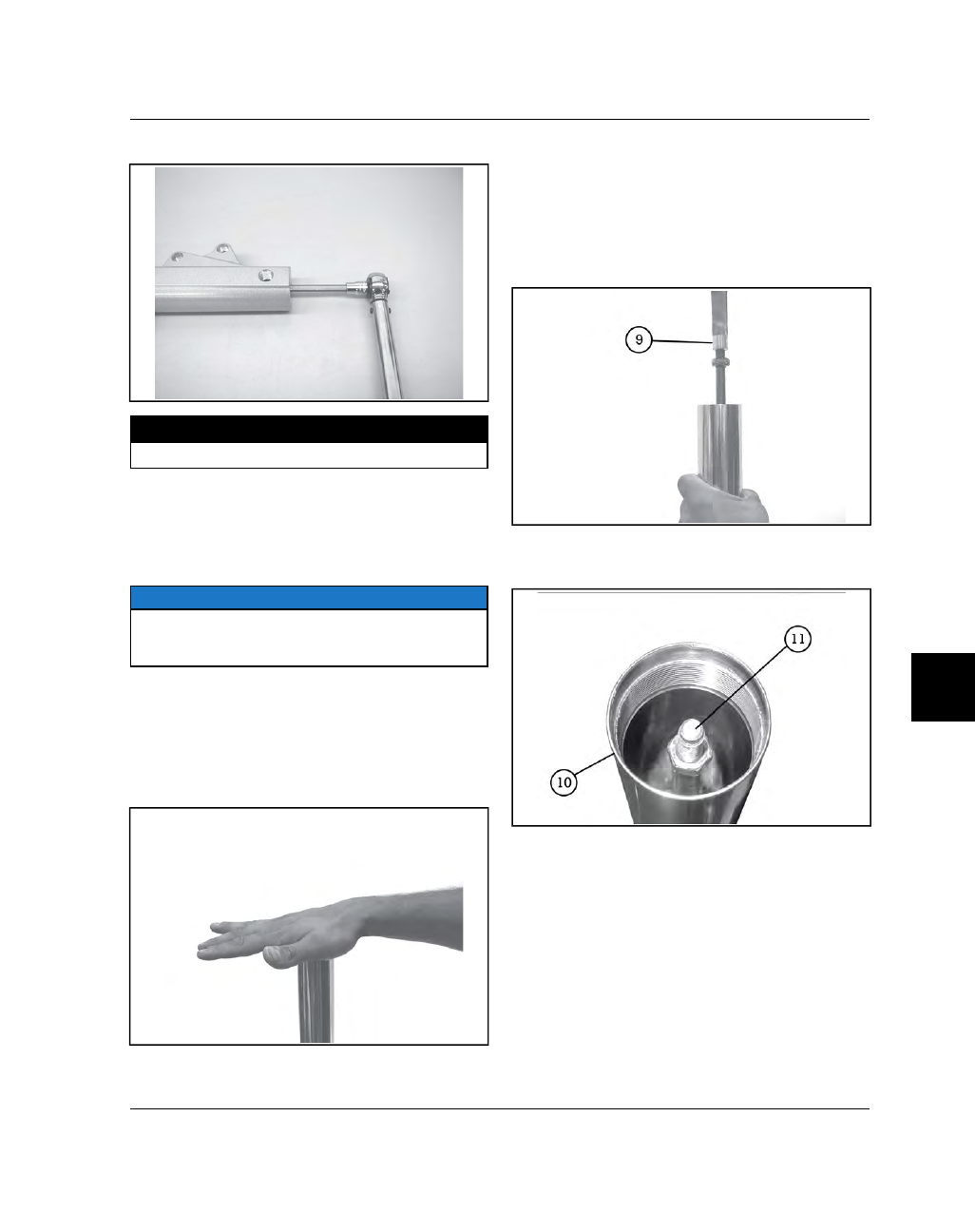
13. Torque cartridge fastener to specification.

TORQUE

Cartridge Fastener:

17 ft-lbs (23 Nm)

Oil Filling / Cartridge Air Bleeding

14. Tip fork leg at an angle to reduce air bubbles.

Slowly add about 350cc of Indian Motorcycle fork
oil

15.

NOTE

The oil quantity slightly exceeds the capacity of the

fork. Final fork oil level must be adjusted correctly as

outlined later in this procedure.

Set fork leg upright.

16. Lift outer tube up to top of travel range.

17. Seal top of tube with your hand and push

downward against air pressure. Hold for 10– 15
seconds. This will help force trapped air from
cartridge and tube.

18. Mount fork assembly upright in a soft jawed vise

by brake caliper mounts on slider.

19. Screw Damper Rod Holder

(PV-49453)

o

onto

cartridge rod.

20. Bleed cartridge by moving shaft up and down to

purge air. Begin with small strokes, increasing
stroke length until all air is removed and damping
is smooth and consistent.

21. Slowly compress inner fork tube

a

and cartridge

rod

s

until they stop (at bottom of travel) and

remove damper rod holder.

STEERING / SUSPENSION

8.30

9927618 R03 - 2017 Indian Motorcycle (Full-Size) Service Manual

22. Loosen thumb fastener on Fork Oil Level Tool

(PV-

59000A)

and slide stop plate to adjust tube to

length of specified oil level.

MEASUREMENT

Fork Oil Level (from top of tube):

5.35 in (136 mm)

.

Set level in tube with spring removed, and inner tube

and damper rod (cartridge rod) fully compressed.

23. Insert fork oil level tool into fork. Be sure fork leg

is

standing

upright

and

fork

tube

is

fully

compressed.

24. Draw excess oil out to the specified level.

25. Install spring with tightly wound coils

d

down.

26. Mount tube in spring compressor and adjust

thumb fasteners to catch spring as outlined for
disassembly.

WARNING

Wear eye / face protection. be sure spring is

engaged properly with pegs of tool as you compress

the spring in the following steps.

27. Attach damper rod holder and hold damper rod

up.

28. Carefully compress spring until fork cap threads

on top of damper rod are visible.

29. Remove extension tool and hold damper rod up,

clear of spring.

30. Screw jamb nut

f

fully onto damper rod until

bottomed.

31. Place backing washer

g

on top of spring.

32. Place a new o-ring on fork cap and screw cap

FULLY onto damper rod for

maximum

thread

engagement.

33. Hold cap and screw jamb nut up damper rod until

it stops against cap.

STEERING / SUSPENSION

8

8.31

34. Hold jamb nut and torque fork cap to specification.

TORQUE

Fork Cap to Jamb Nut:

11 ft-lbs (15 Nm)

35. Slowly release spring pressure and remove fork

leg from spring compressor.

36. Install special socket in compressor as outlined for

disassembly.

37. Slowly compress fork tube assembly with drive nut

until fork cap enters the outer tube, and threads
start to make contact.

38. Rotate outer tube to start cap. Use care to avoid

thread damage.

39. After cap thread is started, continue to turn tube

and

adjust

spring

compressor

pressure

as

required until cap is fully seated against top of
outer tube.

40. Tighten

fork

cap

to

outer

tube.

Torque

to

specification.

TORQUE

Fork Cap to Outer Tube:

16 ft-lbs (22 Nm)

FFRROONNTT FFOORRKK IINNSSTTAALLLLAATTIIOONN ((AALLLL M

MOODDEELLSS))

NOTE

Clean the fork tubes and the clamping surfaces of the

triple clamps to remove any oil or grease prior to

installation.

1. Install one fork tube assembly into lower triple

clamp.

STEERING / SUSPENSION

8.32

9927618 R03 - 2017 Indian Motorcycle (Full-Size) Service Manual

2. Continue to slide tube through lower triple clamp

and into upper triple clamp. Stop when the top of
the fork cap is flush with the top of the upper triple
clamp.

3. Torque the bottom fastener on the lower triple

clamp

q

.

4. Torque the top fastener on the lower triple clamp

w

.

5. REPEAT torque process in steps 3 & 4.

6. Torque the upper triple clamp fastener

e

.

TORQUE

Lower Triple Clamp Fasteners:

18 ft-lbs (24 Nm)

Upper Triple Clamp Fastener:

18 ft-lbs (24 Nm)

7. Repeat steps 1 through 6 for the other fork tube.

8. Install brake line guides (if removed).

9. Install front wheel. See Front Wheel, Removal /

Installation, page 8.18.

10. Install brake calipers. See Front Caliper Service,

page 9.31.

11. Install front fender. See Front Fender Installation,

page 7.27.

12. Install fairing.

Chieftain Dark Horse:

See Outer Fairing

Installation - (Chieftain Dark Horse), page 7.49

Chieftain / Roadmaster:

See Outer Fairing

Installation - (Chieftain / Roadmaster), page 7.55

13.

Chief Classic / Chief Vintage / Chief Dark
Horse / Springfield:

Install headlight bucket and nacelle.

14. Inspect all fasteners for proper torque. Inspect

hoses and wiring for proper routing.

15. Lower front end of motorcycle to the ground and

test front suspension / fork operation.

STEERING / SUSPENSION

8

8.33

TTRRIIPPLLEE CCLLAAM

MPP RREEM

MOOVVAALL

WARNING

This procedure requires raising and supporting

the motorcycle so that the front wheel is off the

ground. Precautions should be taken to ensure

the motorcycle is properly stabilized at all times.

Failure to properly support motorcycle may result

in personal injury or damage to the motorcycle.

CAUTION

Do not twist the brake hose or brake line. Do not

allow calipers to hang from the brake hose. Secure

calipers in such a way to avoid hose damage.

CAUTION

CALIFORNIA & INTERNATIONAL MODELS: Remove

the charcoal canister prior to raising motorcycle

wheels off the ground. As the swingarm lowers it can

contact the canister hose fittings and damage them.

1. Secure the motorcycle in an upright position with

tie-down straps and a platform jack positioned
beneath the engine cases.

NOTE

Do not operate the front brake lever with the calipers

or wheel removed.

2. Remove

the

front

fender.

See

Front

Fender

Removal, page 7.26.

3. Remove front wheel. See Front Wheel, Removal /

Installation, page 8.18.

Chieftain Dark Horse:

4. Remove

fairing

assembly.

See

Outer

Fairing

Removal - (Chieftain Dark Horse), page 7.45.

Chieftain / Roadmaster:

5. Remove

fairing

assembly.

See

Outer

Fairing

Removal - (Chieftain / Roadmaster), page 7.51

Chief Classic / Chief Vintage / Chief Dark
Horse / Springfield:

6. Remove nacelle and headlight bucket.

ALL Models

7. Remove the handlebar / riser assembly. See

Handlebar, Removal / Installation (All Models
except Chieftain / Roadmaster), page 8.14 
or
Handlebar Removal / Installation (Chieftain /
Roadmaster), page 8.16.

8. Remove fork tubes. See Front Fork Removal (All

Models), page 8.21.

9. Remove brake line guides from upper and lower

triple clamp.

10. Remove center nut

q

and washer on upper triple

clamp.

11. Slide upper triple clamp off steering stem.

STEERING / SUSPENSION

8.34

9927618 R03 - 2017 Indian Motorcycle (Full-Size) Service Manual

12. Remove stem adjuster nut

w

with a suitable

spanner socket.

13. Remove lower triple clamp, with steering stem, and

lower bearing (outer race will remain in head
tube).

14. Inspect bearings and bearing races.

FFRROONNTT FFOORRKK LLOOCCKK RREEM

MOOVVAALL // IINNSSTTAALLLLAATTIIOONN

IMPORTANT

Fork lock fasteners must be replaced when fork lock

is removed. Do not reuse fork lock fasteners.

1. Perform steps 1– 10 of

Triple Clamp Removal

procedure.

2. Remove two fork lock fasteners

q

and remove fork

lock

w

.

3. Install NEW fork lock

w

and Install two NEW

fasteners

q

. Torque fasteners to specification.

TORQUE

Fork Lock Fasteners:

18 ft-lbs (24 Nm)

STEERING / SUSPENSION

8

8.35

TTRRIIPPLLEE CCLLAAM

MPP IINNSSTTAALLLLAATTIIOONN // SSTTEEEERRIINNGG HHEEAADD

BBEEAARRIINNGG AADDJJUUSSTTM

MEENNTT

1. Inspect both top and bottom bearing races for

pitting, dents, or worn surface. Replace bearings
and races as a set if they are worn or damaged.

2. Be sure lower stem bearing

q

is seated against

step on lower triple clamp. Apply all purpose
grease to bearing and install lower triple clamp /
stem to frame.

3. Grease and install upper bearing

w

onto stem and

push it down until seated in upper bearing race.

4. Screw adjuster nut

e

(shoulder side down) onto

the steering stem until it is finger tight.

5. Turn triple clamp assembly fully to the right.

6. Torque adjuster nut to specification using suitable

spanner wrench.

TORQUE

Steering Stem Bearing Adjuster Nut:

29 ft-lbs (39 Nm)

7. Place a mark on the frame in alignment with one of

the slots on the adjuster nut.

8. Turn lower triple clamp from lock to lock five times

and

return to full right

position.

9. Loosen adjuster nut 90 degrees (1/4 turn) so the

reference mark on frame is aligned with the next
one of the four slots on the stem nut.

10. Set upper triple clamp in place on stem. Install

washer

r

and nut

t

and tighten top nut until it is

finger tight.

NOTE

Nut will be torqued after fork tubes are installed.

STEERING / SUSPENSION

8.36

9927618 R03 - 2017 Indian Motorcycle (Full-Size) Service Manual

11. Slide fork tubes through lower triple clamp and

into upper triple clamp. Align top edge of fork cap
with top edge of upper triple clamp and hold in
position.

12. Tighten top triple clamp pinch fastener enough to

hold tubes in place. Leave lower triple clamp pinch
fasteners

loose

.

13. Torque the top steering stem nut to specification.

TORQUE

Top Steering Stem Nut:

72 ft-lbs (98 Nm)

NOTE

CHECK STEERING STEM BEARINGS at this time. Pull

firmly on fork tubes with a front-to-rear motion. If

movement can be felt in steering bearings,

disassemble and go back to STEP 10. Tighten

steering stem adjuster nut an additional 5 degrees,

and reassemble following STEPS 10–15. Repeat this

procedure until no play can be felt.

14. Verify fork tube height in upper triple clamp. The

top of the fork cap should be flush with the top of
the upper triple clamp.

15. Torque the upper triple clamp pinch fasteners

(both sides) to specification.

TORQUE

Upper Triple Clamp Pinch Fasteners:

18 ft-lbs (24 Nm)

16. Torque bottom fasteners on lower triple clamp to

specification.

17. Torque top fasteners on lower triple clamp to

specification.

TORQUE

Lower Triple Clamp Pinch Fasteners (ALL):

18 ft-lbs (24 Nm)

18. Repeat STEPS 15–17.

19. Install

handlebar

assembly.

See

Handlebar,

Removal / Installation (All Models except Chieftain
/ Roadmaster), page 8.14 
or Handlebar Removal /
Installation (Chieftain / Roadmaster), page 8.16

20. Install front wheel. See Front Wheel, Removal /

Installation, page 8.18

21. Verify all fasteners are installed and properly

torqued.

TTRROOUUBBLLEESSHHOOOOTTIINNGG

PROBLEM

POSSIBLE CAUSE

REPAIR RECOMMENDED

Heavy Steering

Steering Stem Nut Over Tightened

Torque to specification

Damaged Steering Stem Bearings
or Races

Replace

Bent Steering Stem

Replace

Front Tire Damaged or Worn

Replace

Low Tire Pressure

Inflate to specification

Pulls to One Side or Wanders

Damaged Steering Stem Bearings
or Races

Replace

Steering Stem Nut Over Tightened
or Under Tightened

Torque to specification

Low Tire Pressure

Inflate to specification

Rear Wheel Not Aligned Correctly

Align

Bent Front Axle

Replace

Damaged or Excessively Worn
Front Tire / Incorrect Tire

Replace

Damaged Wheel Bearings

Replace

Damaged Swing Arm Bearings

Replace

STEERING / SUSPENSION

8

8.37

PROBLEM

POSSIBLE CAUSE

REPAIR RECOMMENDED

Loose Swing Arm Pivot Nut

Torque to specification

Bent Frame or Swingarm

Replace

Handlebars Oscillate (Wobble)

Bent Front Axle

Replace

Wheel Has Excessive Runout

True (Spoked) / Replace (Cast)

Tire Mounted Incorrectly

Check Mounting and Balance

Damaged Tire / Worn Tire

Replace

Loose Steering Stem Nut

Torque to specification

Incorrect Tire

Replace

Incorrect Tire Pressure

Correct

Noise Coming From Front
Suspension

Worn Fork Bushings

Rebuild Forks

Low Fork Fluid

Determine Cause / Replace Fork
Oil

Loose Fasteners

Torque to specification

Loose Steering Stem Bearings

Determine Cause / Correct

Front Wheel Oscillates (Wobbles)

Bent Front Rim

Replace

Damaged Front Wheel Bearings

Replace

Damaged or Incorrect Tire

Replace

Front Wheel Oscillates (Wobbles)

Loose Axle

Torque to specification

Fork Tube Height Unequal

Install Correctly

Fork Oil Level Unequal

Set Correctly

Fork Spring Free Length Different
Between Right & Left

Replace

Wheel Assembly Out-of-Balance

Balance

Low Tire Pressure

Inflate to specification

Front Suspension Too Soft

Weak Fork Springs

Replace

Low Fork Oil Level

Determine Cause/Replace Fork Oil

Wrong Weight Fork Oil

Replace

Contaminated and/or Deteriorated
Fork Oil

Replace

Low Tire Pressure

Set Correctly

Front Suspension Too Hard

Tire Pressure Too High

Set Correctly

Bent Fork Tubes

Replace

Wrong Weight Fork Oil

Replace

Too Much Fork Oil

Set Correctly

Plugged Oil Passages

Rebuild Front Forks

STEERING / SUSPENSION

8.38

9927618 R03 - 2017 Indian Motorcycle (Full-Size) Service Manual

PROBLEM

POSSIBLE CAUSE

REPAIR RECOMMENDED

Damaged Sliders

Replace

Forks Binding

Correct

Wheel Turns Hard

Damaged Wheel Bearings

Replace

Front Axle Bent

Replace

Brake Dragging
(Hydraulic or Mechanical Problem)

Repair as Necessary

Brake Dragging (Bent Disc)

Replace

Improper Assembly After Repairs

Correct as Necessary

STEERING / SUSPENSION

8

8.39

RREEAARR W

WHHEEEELL // SSUUSSPPEENNSSIIOONN

GGEENNEERRAALL IINNFFOORRM

MAATTIIOONN

SSEERRVVIICCEE NNOOTTEESS

WARNING

This motorcycle was produced with the designated

tires as original equipment. The testing to ensure

stability and superior handling was done using the

OEM tires. Using non-OEM tires could result in poor

motorcycle stability and handling, which can lead to

a crash resulting in serious injury or death. Use only

the recommended tires inflated to the recommended

tire pressures.

Tubeless tires are used on certain Indian Motorcycle
models. Operating the motorcycle with damaged rims
creates a safety hazard including air pressure loss,
steering imbalance and/or reduced steering control.
Do not attempt to repair or straighten damaged cast or
spoked rims. Indian Motorcycle Chief Classic and
Vintage models are equipped with spoked tube-type
rims. Small imperfections in the alignment of these
rims can be corrected using an approved wheel truing
stand and spoke wrench (commercially available).
Always use genuine Indian Motorcycle parts or
equivalent so that quality is not compromised. The use
of tire valves and valve cores other than original
equipment replacement Indian Motorcycle parts could
cause tire deflation which may lead to loss of control,
resulting in injury or death. Do not allow any
motorcycle to leave your service area without tire
valve caps securely installed.

• The rear shock absorber is serviceable.
• Refer to Maintenance chapter for maintenance of

rear wheel & suspension components, and
suspension ride height adjustment.

SSPPEECCIIAALL TTOOOOLLSS

SPECIAL TOOL

PART NUMBER

Swing-arm Bushing Tool

PF-51237

Shock Spanner Wrench

PV-46993

Bearing Removal /
Installation Kit

PF-51324

Platform Jack

Commercially Available

TTOORRQQUUEE SSPPEECCIIFFIICCAATTIIOONNSS -- RREEAARR W

WHHEEEELL

PART / FASTENER

TORQUE

SPECIFICATION

Belt Guard, Lower

96 in-lbs (11 Nm)

Brake Disc

22 ft-lbs (30 Nm)

Drive Sprocket Cover

84 in-lbs (10 Nm)

Drive Sprocket Lock Plate

88 in-lbs (10 Nm)

Drive Sprocket Nut

180 ft-lbs (244 Nm)

Gusset Plate

55 ft-lbs (75 Nm)

P-Clamp Fasteners (Brake
Line / W.S.S.)

84 in-lbs (10 Nm)

Pushrod Fastener, Upper

55 ft-lbs (75 Nm)

Rear Axle Nut

Step 1: 15 ft-lbs
(20 Nm)

Step 2: 65 ft-lbs
(88 Nm)

Rear Caliper Mounting
Fasteners

31 ft-lbs (42 Nm)

Shock Absorber Fasteners
(Upper & Lower)

55 ft-lbs (75 Nm)

Shock Air Line Jamb Nut
(Air Shock)

20 ft-lbs (27 Nm)

Swingarm Nut (LH)

65 ft-lbs (88 Nm)

Swingarm Shaft, Initial
Torque (Before Outer Nut
Installation)

8 ft-lbs (11 Nm)

Swingarm Shaft, Jamb Nut

75 ft-lbs (102 Nm)

Wheel Speed Sensor

96 in-lbs (11 Nm)

STEERING / SUSPENSION

8.40

9927618 R03 - 2017 Indian Motorcycle (Full-Size) Service Manual

SSEERRVVIICCEE SSPPEECCIIFFIICCAATTIIOONNSS

ITEM

STANDARD

SERVICE LIMIT

Axle Runout

-

.20 mm (.008")

Rear Wheel Runout

Axial

.80 mm (.030 inch)

2.0 mm (.080”)

Radial

.80 mm (.030 inch)

2.0 mm (.080”)

Rear Wheel Size /
Type

Classic / Vintage

16” x 5” Spoked

Chieftain /
Roadmaster / Dark
Horse / Springfield

16” x 5” Cast

Rear Wheel Travel

Classic / Vintage /
Dark Horse

3.7” (9.4 cm)

Chieftain /
Roadmaster /
Springfield

4.5” (11.4 cm)

Shock Spring Free
Length

Classic / Vintage /
Dark Horse

8.0” (203.2 cm)

Chieftain /
Roadmaster /
Springfield

8.0” (203.2 cm)

Shock Spring
Installed Length
(Standard)

Classic / Vintage /
Dark Horse

Perform Ride Height Adjustment

Chieftain /
Roadmaster /
Springfield

Suspension Ride
Height

All Models

Refer to Maintenance chapter for
Ride Height Measurement procedure

Spring Rate

Classic / Vintage /
Dark Horse

450 lbs / in

Chieftain /
Roadmaster /
Springfield

400 lbs / in

Swing Arm Pivot Shaft Runout

Not Applicable

.20 mm (.008")

Swing Arm Pivot Shaft O.D.

LH Ball Bearing Journal: 19.965–
19.99 mm / RH Needle Bearing
Journal: 24.95–25.00 mm

Swing Arm Needle Bearing Bore O.D. (RH)

31.946–31.972 mm

Swing Arm Ball Bearing Bore O.D. (LH)

41.967–41.992 mm

Wheel bearing O.D. (approx)

51.987–52.00 mm

Wheel bearing I.D. (approx)

19.998–20.00 mm

STEERING / SUSPENSION

8

8.41

AASSSSEEM

MBBLLYY VVIIEEW

WSS

RREEAARR SSUUSSPPEENNSSIIOONN

STEERING / SUSPENSION

8.42

9927618 R03 - 2017 Indian Motorcycle (Full-Size) Service Manual

NUMBER

PART DESCRIPTION

TORQUE SPECIFICATION (IF

APPLICABLE)

q

Retaining Ring

-

w

Rocker Pivot Shaft

-

e

Nut, Gusset Plate — M10 x 1.5 (QTY.6)

-

r

Gusset Plate, Swingarm

-

t

Fastener, Pushrod — M10 x 1.5 x 40 (QTY.1)

55 ft-lbs (75 Nm)

y

Fastener, Shock — M10 x 60 (QTY.1)

55 ft-lbs (75 Nm)

u

Rocker Arm Assembly

-

i

Shock

-

o

Spherical Bearing

-

a

Nut, Swingarm — M18 x 1.5 (QTY.1)

65 ft-lbs (88 Nm)

s

Spacer, Pivot (LH Outer)

-

d

Spacer, Pivot (LH)

-

f

Retaining Ring

-

g

Ball Bearing — M42 x 20 x 12 (QTY.2)

-

h

Pushrod

-

j

Swingarm

-

k

Gusset Plate (RH), Swingarm

-

l

Seal

-

1(

Bearing, Needle

-

2)

Suspension Pivot

-

2!

Nut, Jamb — M27 x 1.5 (QTY.1)

75 ft-lbs (102 Nm)

2@

Fastener — M10 x 1.5 x 50 (QTY.4)

55 ft-lbs (75 Nm)

2#

Belt Guard, Lower

-

2$

Sleeve (QTY.2)

-

2%

Fastener — M6 x 1.0 x 20 (QTY.2)

96 in-lbs (11 Nm)

2^

Nut — M18 x 1.5 (QTY.1)

Step 1: 15 ft-lbs (20 Nm)

Step 2: 65 ft-lbs (88 Nm)

2&

Axle Adjuster (RH)

-

2*

Nut — M8 x 1.25 (QTY.2)

-

2(

Axle Adjuster (QTY.2)

-

3)

Wheel Spacer (RH)

-

3!

Axle, Rear

-

STEERING / SUSPENSION

8

8.43

RREEAARR SSHHOOCCKK // PPUUSSHHRROODD

NUMBER

PART DESCRIPTION

TORQUE (IF APPLICABLE)

q

Retaining Ring

-

w

Pivot Shaft, Rocker

-

e

Fastener, Shock — M10 x 60 (QTY.1)

55 ft-lbs (75 Nm)

r

Rocker Arm

-

t

Fastener, Pushrod — M10 x 1.5 x 40 (QTY.1)

55 ft-lbs (75 Nm)

y

Nut, Gusset Plate — M10 x 1.5 (QTY.6)

-

u

Gusset Plate, Swingarm

-

i

Spherical Bearing

-

o

Pushrod

-

a

Gusset Plate, Swingarm

-

s

Shock Assembly

-

d

Fastener — M10 x 1.5 x 50 (QTY.4)

55 ft-lbs (75 Nm)

STEERING / SUSPENSION

8.44

9927618 R03 - 2017 Indian Motorcycle (Full-Size) Service Manual

RREEAARR W

WHHEEEELL

NUMBER

PART DESCRIPTION

TORQUE (IF APPLICABLE)

q

Belt, Drive — 152T / 24 mm

-

w

Bearing, Cushion Drive

-

e

Spacer, Inner

-

r

Sprocket — 66T

-

t

Damper, Cushion Drive

-

y

Spacer, Wheel

-

u

Bearing, Wheel (RH) — 20 mm X 52 mm X 15 mm -

i

Spacer, Bearing — 130 mm

-

o

Rim

-

a

Seal

-

STEERING / SUSPENSION


Content      ..     25      26      27      28     ..