Indian motorcycle 2017. Service Manual - page 26
8.13
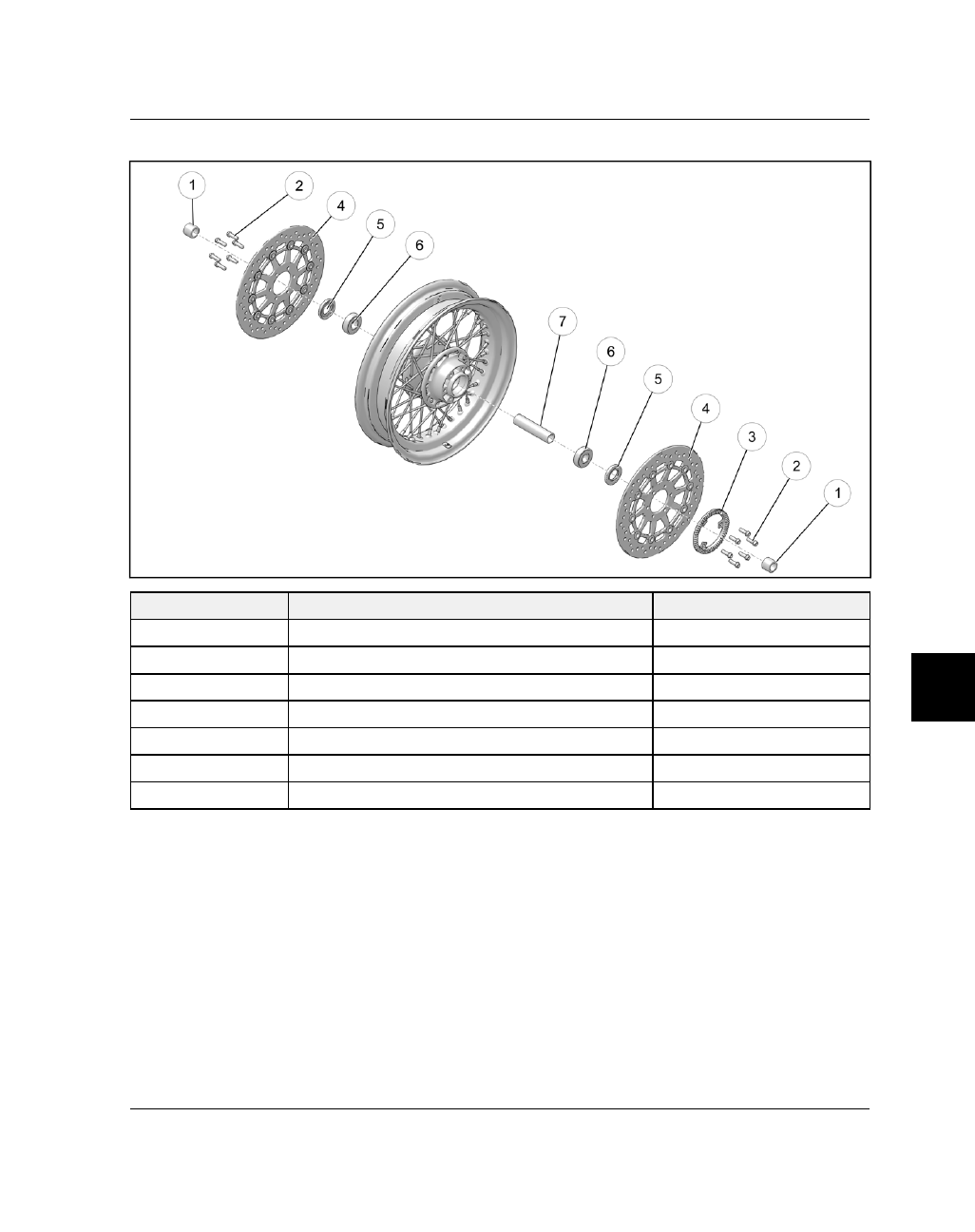
FFRROONNTT W
WHHEEEELL -- SSPPOOKKEEDD
NUMBER
PART DESCRIPTION
TORQUE (IF APPLICABLE)
q
Outer Bearing Spacer
-
w
Pulse Wheel / Brake Disc Fastener (QTY.6)
22 ft-lbs (30 Nm)
e
ABS Pulse Wheel
-
r
Brake Disc
-
t
Seal
-
y
Wheel Bearing
-
u
Inner Bearing Spacer
-