Indian motorcycle 2017. Service Manual - page 24


  Главная      Manuals     Indian motorcycle 2017. Service Manual


Search            copyright infringement  


Content      ..     22      23      24      25     ..


Indian motorcycle 2017. Service Manual - page 24


7.40

9927618 R03 - 2017 Indian Motorcycle (Full-Size) Service Manual

CCHHIIEEFF CCLLAASSSSIICC // CCHHIIEEFF DDAARRKK HHOORRSSEE // CCHHIIEEFF

VVIINNTTAAGGEE // SSPPRRIINNGGFFIIEELLDD

IINNSSTTRRUUM

MEENNTT PPAANNEELL RREEM

MOOVVAALL // IINNSSTTAALLLLAATTIIOONN

1.

Position the motorcycle on it’s side stand on a flat
surface.

2.

Remove the console cover. See STEPS 1– 5 of Fuel
Tank Removal, page 4.15.
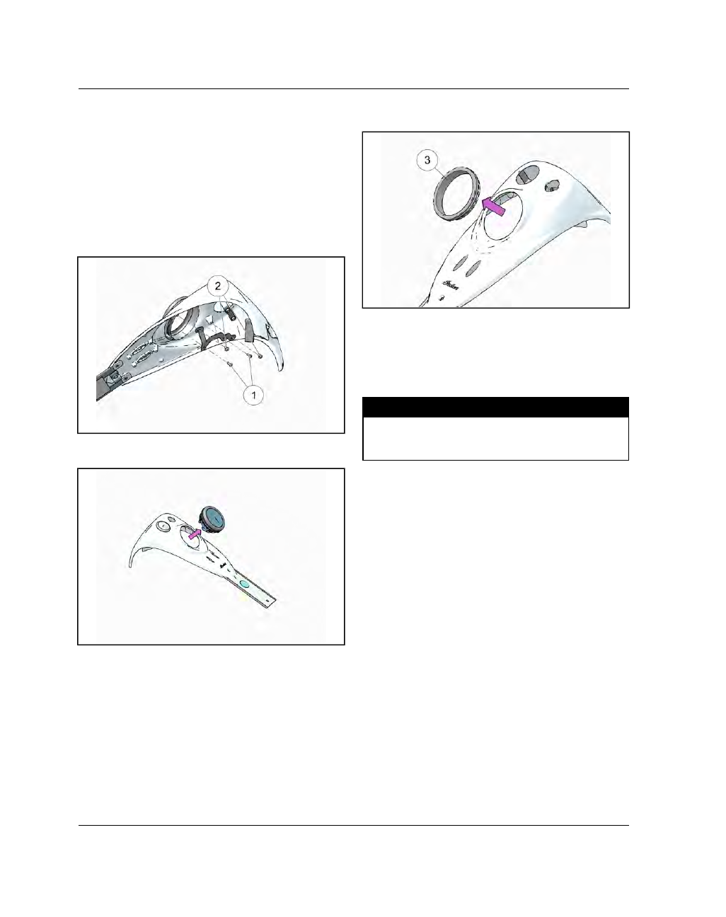
3.

Remove

fasteners

q

securing

bracket

to

speedometer head and remove fasteners

w

securing the speedometer bracket to the console
cover.

4.

Remove the bezel from the speedometer and lift
the speedometer head out of the rubber grommet.

5.

Remove the rubber grommet

e

from the console

cover.

6.

INSTALLATION is performed by reversing the
removal procedure. Using a mild soapy water
solution on the rubber seal will make it easier
to press the instrument panel into position.

7.

Torque

speedometer

bracket

fasteners

to

specification.

TORQUE

Speedometer to Bracket Fasteners:

15 in-lbs (2 Nm)

Bracket to Console Cover Fasteners:

43 in-lbs (5

Nm)

FRAME / BODY

7

7.41

NNAACCEELLLLEE RREEM

MOOVVAALL

CAUTION

Protect painted surfaces on the front fender and fuel

tank prior to beginning the following procedure. Use

care when removing the nacelle so the chrome does

not get scratched.

CAUTION

During disassembly, pay close attention to harness

routing and connector orientation. Always route

electrical wiring the same way as it was removed to

avoid damaging wires and connectors.

1.

Remove windshield assembly, if equipped.

2.

Remove two fasteners

q

at the top of the nacelle

assembly.

3.

Remove two fasteners

w

securing the console

cover to the fuel tank and lift console back and set
on protected fuel tank.

4.

Remove two fasteners per side

e

securing the

windshield mounting bracket assembly.

5.

Rotate the auxiliary lamp assembly forward and
lower out of the way.

6.

Pull the rear portion of the nacelle assembly back
toward the fuel tank to expose the handlebar
risers.

7.

Loosen the front handlebar clamp fasteners

r

and

rotate the handlebar up so the rear portion of the
nacelle can be removed.

FRAME / BODY

7.42

9927618 R03 - 2017 Indian Motorcycle (Full-Size) Service Manual

8.

Disconnect the auxiliary light switch (if equipped)
and remove the rear portion of the nacelle

t

.

9.

Pull the front portion of the nacelle out far enough
to access the four fasteners

y

securing the

headlamp bucket and remove.

10. Pull the headlamp bucket out far enough to

disconnect the headlamp connector and remove
the bucket assembly

u

.

11. Using a side cutter, carefully clip the six cable ties

securing the harness to the front portion of the
nacelle assembly.

IMPORTANT

Use a marker or tape to index each multi-plug before

disconnecting. Some of the connectors are unmarked

and interchangeable.

12. Disconnect all multi-plugs between the switch

cube and chassis harness and route through the
front portion of the nacelle.

13. Remove nacelle.

FRAME / BODY

7

7.43

NNAACCEELLLLEE IINNSSTTAALLLLAATTIIOONN

CAUTION

During installation of the nacelle assembly, pay close

attention to harness routing and connector

orientation. Always route electrical wiring the same

way as it was removed to avoid damaging wires and

connectors.

1.

Move the front portion of the nacelle into position
and feed the wire harness through the center hole
as shown.

2.

Install new cable ties into all six fir tree clips.

3.

Paying attention to the natural form of the wiring
harness, reconnect all of the multi-plugs between
the chassis and switch cubes.

IMPORTANT

Pay attention to index marks placed on connectors

during disassembly when reconnecting as some of

them are interchangeable.

4.

Secure harness to the front portion of the nacelle
using the newly installed cable ties.

5.

Position the headlamp bucket in front of the
nacelle and reconnect the headlamp bulb.

6.

Install the four headlamp bucket fasteners

q

and

torque to specification.

TORQUE

Headlamp Bucket Fasteners:

75 in-lbs (8 Nm)

7.

Lower the rear portion of the nacelle

w

into

position and reconnect the auxiliary light switch (if
equipped).

FRAME / BODY

7.44

9927618 R03 - 2017 Indian Motorcycle (Full-Size) Service Manual

8.

Rotate the handlebar into the desired position and
torque

the

riser

clamp

fasteners

e

to

specification.

TORQUE

Riser Clamp Fasteners:

18 ft-lbs (24 Nm)

Tighten Front fasteners First, Then Rear

9.

Push the front and rear portions of the nacelle
together into position around the triple clamp.

10. Move the light bar / turn signal assembly into

position and install the four fasteners

r

finger

tight.

NOTE

Verify that the rubber grommets securing the

auxiliary light / turn signal harness have been slid

into place.

11. Install the two fasteners

t

located at the top of the

nacelle and torque to specification.

TORQUE

Upper Nacelle Fasteners:

36 in-lbs (4 Nm)

12. Torque the auxiliary light bar bracket fasteners

r

to specification.

TORQUE

Auxiliary Light Bar Bracket Fasteners:

18 ft-lbs (24

Nm)

13. Move the console cover into position and torque

fasteners to specification.

TORQUE

Console Cover Fasteners:

84 in-lbs (10 Nm)

14. Install windshield assembly, if equipped.

15. Verify that all controls are operating correctly and

the handlebar turns freely from lock to lock.

FRAME / BODY

7

7.45

CCHHIIEEFFTTAAIINN DDAARRKK HHOORRSSEE

OOUUTTEERR FFAAIIRRIINNGG RREEM

MOOVVAALL -- ((CCHHIIEEFFTTAAIINN DDAARRKK

HHOORRSSEE))

NOTE

Place the power windshield in the FULL UP position

prior to fairing removal.

CAUTION

Fasteners removed in STEPS 3 & 5 are different

lengths. It is imperative that the fasteners are

reinstalled in the same positions they are removed

from or damage to outer fairing may occur.

1. Place the motorcycle on a flat surface resting on it’s

side stand.

2. Remove the five fasteners

q

from the windshield

and remove windshield.

NOTE

When removing the five windshield fasteners be sure

to capture the T-nuts as they are not captive.

3. Remove the four LONG fasteners

w

from the top of

the fairing assembly.

4. Using the Body Panel tool

(PV-49955),

gently pry

the LH

e

and RH

r

speaker grill out of the inner

fairing assembly.

5. Remove six fasteners

t

from the inner fairing

assembly.

NOTE

Some fasteners are longer than others, make sure to

note placement of fasteners when removing.

FRAME / BODY

7.46

9927618 R03 - 2017 Indian Motorcycle (Full-Size) Service Manual

6. Remove two fasteners

y

and head light bezel.

7. Remove three fasteners

u

and withdraw the head

light assembly far enough to disconnect electrical
connector.

8. Remove fairing assembly.

FRAME / BODY

7

7.47

IINNNNEERR FFAAIIRRIINNGG RREEM

MOOVVAALL -- ((CCHHIIEEFFTTAAIINN DDAARRKK

HHOORRSSEE))

NOTE

The inner fairing assembly can be removed with the

radio module, power windshield actuator and

speakers intact.

CAUTION

During disassembly, pay close attention to harness

routing and connector orientation. Always route

electrical wiring the same way as it was removed to

avoid damaging wires and connectors.

1. Remove the outer fairing. See Outer Fairing

Removal - (Chieftain Dark Horse), page 7.45.

2. Remove the instrument cluster. See Instrument

Panel Removal / Installation - (Chieftain Dark
Horse), page 7.50.

3. Remove the four nuts and washers

q

as shown.

4. Using a side-cutter, carefully clip the four cable ties

w

securing the wiring harness to the inner fairing.

5. Using a side-cutter, carefully clip the outboard

cable ties

e

.

IMPORTANT

Use a marker or tape to index each multi-plug before

disconnecting. Some of the connectors are unmarked

and interchangeable.

6. Disconnect all multi-plugs between the fairing and

chassis harnesses.

7. Disconnect the 12V accessory socket connector

and fog lamp button.

8. Lift the inner fairing assembly off of the triple

clamp studs and route wire through the access
hole.

FRAME / BODY

7.48

9927618 R03 - 2017 Indian Motorcycle (Full-Size) Service Manual

IINNNNEERR FFAAIIRRIINNGG IINNSSTTAALLLLAATTIIOONN -- ((CCHHIIEEFFTTAAIINN DDAARRKK

HHOORRSSEE))

CAUTION

During installation of the inner fairing, pay close

attention to harness routing and connector

orientation. Always route electrical wiring the same

way as it was removed to avoid damaging wires and

connectors.

1. Rest the inner fairing assembly on the lower

mounting studs

q

and tilt forward.

2. Carefully route all loose wires through the access

hole in the inner fairing mount.

3. Install the inner fairing assembly on the four triple

clamp studs

w

and install washers and nuts finger

tight.

4. Verify that no wires or connectors have been

pinched between the inner fairing and the triple
clamp and torque mounting nuts to specifications.

TORQUE

Inner Fairing Mounting Nuts:

12 ft-lbs (16 Nm)

5. Route the fog lamp button and 12V accessory

socket harnesses so they can be secured by their
respective cable ties

e

, and reconnect.

6. Paying attention to the natural form of the wiring

harness, reconnect all of the multi-plugs between
the chassis and inner faring.

IMPORTANT

Pay attention to index marks placed on connectors

during disassembly when reconnecting as some of

them are interchangeable.

7. Connect the radio antenna and radio multi-plugs.

8. Remove the cut cable ties from the four fir tree

clips and install new cable ties.

9. Position the wiring harness so it can be secured by

the four cable ties.

10. Replace the cable ties securing the fog lamp button

and 12V accessory socket to the inner fairing.

11. Install the outer fairing assembly. See Outer Fairing

Installation - (Chieftain Dark Horse), page 7.49

12. Install the instrument cluster. See Instrument Panel

Removal / Installation - (Chieftain Dark Horse),
page 7.50

FRAME / BODY

7

7.49

OOUUTTEERR FFAAIIRRIINNGG IINNSSTTAALLLLAATTIIOONN -- ((CCHHIIEEFFTTAAIINN DDAARRKK

HHOORRSSEE))

CAUTION

Fasteners installed in STEPS 4 & 6 are different

lengths. It is imperative that the fasteners are

installed in the correct location or damage to outer

fairing may occur. Reference the drawing below for

proper fastener locations.

1. Install outer fairing assembly

q

onto fairing

subframe as shown.

2. Install the head light assembly

w

and torque

fasteners to specification.

TORQUE

Head Light Bracket Fasteners:

75 in-lbs (8 Nm)

3. Install head light bezel and torque fasteners

e

to

specification.

TORQUE

Head Light Bezel:

36 in-lbs (4 Nm)

4. Install the six fasteners

r

into the inner fairing

assembly and torque to specification.

NOTE

Refer to the notes made when removing the

fasteners. Some fasteners are longer than others,

make sure the correct placement of fasteners when

installing.

TORQUE

Inner Fairing Fasteners:

36 in-lbs (4 Nm)

5. Install the LH and RH speaker grills.

FRAME / BODY

7.50

9927618 R03 - 2017 Indian Motorcycle (Full-Size) Service Manual

6. Install the four fasteners

t

into the top of the

fairing assembly and torque to specification.

TORQUE

Upper Fairing Fasteners:

36 in-lbs (4 Nm)

7. Install the windshield and torque fasteners

y

to

specification.

TORQUE

Windshield Fasteners:

36 in-lbs (4 Nm)

IINNSSTTRRUUM

MEENNTT PPAANNEELL RREEM

MOOVVAALL // IINNSSTTAALLLLAATTIIOONN --

((CCHHIIEEFFTTAAIINN DDAARRKK HHOORRSSEE))

1. Position the motorcycle on it’s side stand on a flat

surface.

2. Using Body Panel tool

(PV-49955)

or a similar tool,

alternately lift the LH side

q

and RH side

w

of the

instrument panel until the rubber retainer is free.

3. Lift instrument panel out of the fairing mount and

disconnect the single multi-plug.

4.

INSTALLATION is performed by reversing the
removal procedure. Using a mild soapy water
solution on the rubber seal will make it easier
to press the instrument panel into position.

CAUTION

Do not use alcohol on seal for installation.

FRAME / BODY

7

7.51

CCHHIIEEFFTTAAIINN // RROOAADDM

MAASSTTEERR

OOUUTTEERR FFAAIIRRIINNGG RREEM

MOOVVAALL -- ((CCHHIIEEFFTTAAIINN // RROOAADDM

MAASSTTEERR))

NOTE

Place the power windshield in the FULL UP position

prior to fairing removal.

1. Place the motorcycle on a flat surface resting on it’s

side stand.

2. Remove two fasteners

q

and head light bezel.

3. Remove three fasteners

w

and withdraw the head

light assembly far enough to disconnect electrical
connector.

4. Remove the five fasteners

e

from the windshield

and remove windshield.

NOTE

When removing the five windshield fasteners be sure

to capture the T-nuts as they are not captive.

5. Remove the four fasteners

r

from the top of the

fairing assembly.

FRAME / BODY

7.52

9927618 R03 - 2017 Indian Motorcycle (Full-Size) Service Manual

6. Remove two fasteners from both the left and right

side speaker grills

t

. Pull speaker grills bottom

out and then downward to remove.

7. Remove two short fasteners, four longer fasteners

y

and two washers

u

from the inner fairing

assembly.

NOTE

Some fasteners are longer than others, make sure to

note placement of fasteners when removing.

8. Remove fairing assembly.

FRAME / BODY

7

7.53

IINNNNEERR FFAAIIRRIINNGG RREEM

MOOVVAALL -- ((CCHHIIEEFFTTAAIINN //

RROOAADDM

MAASSTTEERR))

CAUTION

During disassembly, pay close attention to harness

routing and connector orientation. Always route

electrical wiring the same way as it was removed to

avoid damaging wires and connectors.

1. Remove the outer fairing. See Outer Fairing

Removal - (Chieftain / Roadmaster), page 7.51

2. Remove the instrument cluster. See Ride Command

System Removal, page 7.57

3. Remove four nuts

q

and washers securing the

inner fairing support to the triple clamp assembly.

4. Disconnect all multi plugs in harness holder

bracket.

IMPORTANT

Use a marker or tape to index each multi-plug before

disconnecting. Some of the connectors are unmarked

and interchangeable.

5. Lift the inner fairing assembly off of the triple

clamp studs and route wire through the access
hole.

FRAME / BODY

7.54

9927618 R03 - 2017 Indian Motorcycle (Full-Size) Service Manual

IINNNNEERR FFAAIIRRIINNGG IINNSSTTAALLLLAATTIIOONN -- ((CCHHIIEEFFTTAAIINN //

RROOAADDM

MAASSTTEERR))

CAUTION

During installation of the inner fairing, pay close

attention to harness routing and connector

orientation. Always route electrical wiring the same

way as it was removed to avoid damaging wires and

connectors.

1. Rest the inner fairing assembly on the lower

mounting studs

q

and tilt forward.

2. Carefully route all loose wires through the access

hole in the inner fairing mount.

3. Install the inner fairing assembly on the four triple

clamp studs

w

and install washers and nuts finger

tight.

4. Verify that no wires or connectors have been

pinched between the inner fairing and the triple
clamp and torque mounting nuts to specifications.

TORQUE

Inner Fairing Mounting Nuts:

12 ft-lbs (16 Nm)

5. Connect all multi plugs in harness holder bracket.

6. Paying attention to the natural form of the wiring

harness, reconnect all of the multi-plugs between
the chassis and inner faring.

IMPORTANT

Pay attention to index marks placed on connectors

during disassembly when reconnecting as some of

them are interchangeable.

7. Install the outer fairing assembly. See Outer Fairing

Installation - (Chieftain / Roadmaster), page 7.55

8. Install the instrument cluster. See Ride Command

System Installation, page 7.58

FRAME / BODY

7

7.55

OOUUTTEERR FFAAIIRRIINNGG IINNSSTTAALLLLAATTIIOONN -- ((CCHHIIEEFFTTAAIINN //

RROOAADDM

MAASSTTEERR))

1. Install outer fairing assembly onto fairing subframe

as shown.

2. Install the head light assembly

w

and torque

fasteners to specification.

TORQUE

Head Light Bracket Fasteners:

75 in-lbs (8 Nm)

3. Install head light bezel and torque fasteners

q

to

specification.

TORQUE

Head Light Bezel:

36 in-lbs (4 Nm)

4. Install two short fasteners and four longer fasteners

y

into the inner fairing assembly. Install one

washer

u

per side between the lower fasteners

and the fairing. Torque fasteners to specification.

NOTE

Some fasteners are longer than others, make sure to

note placement of fasteners when removing.

TORQUE

Inner Fairing Fasteners:

36 in-lbs (4 Nm)

FRAME / BODY


Content      ..     22      23      24      25     ..