Indian motorcycle 2017. Service Manual - page 22


  Главная      Manuals     Indian motorcycle 2017. Service Manual


Search            copyright infringement  


Content      ..     20      21      22      23     ..


Indian motorcycle 2017. Service Manual - page 22


7.8

9927618 R03 - 2017 Indian Motorcycle (Full-Size) Service Manual

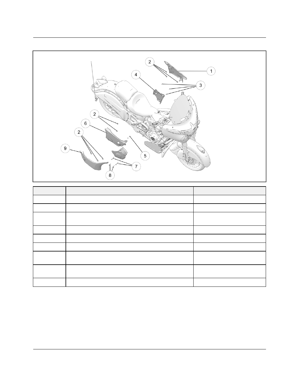
SSIIDDEE PPAANNEELLSS

NUMBER

PART DESCRIPTION

TORQUE (IF APPLICABLE)

q

Side Cover, Left Hand Upper

w

Rubber Grommet

e

Fastener, Left Hand Lower Side Cover — M6 x 1.0 x 15
(QTY.3)

84 in-lbs (10 Nm)

r

Side Cover, Left Hand Lower

t

Rubber Isolator

y

Side Cover, Right Hand Lower

u

Fastener, Right Hand Sprocket Cover — M6 x 1.0 x 70
(QTY.2)

84 in-lbs (10 Nm)

i

Fastener, Right Hand Sprocket Cover — M6 x 1.0 x 40
(QTY.2)

84 in-lbs (10 Nm)

o

Side Cover, Right Hand Upper

FRAME / BODY

7

7.9

SSEEAATT -- AALLLL ((EEXXCCEEPPTT RROOAADDM

MAASSTTEERR))

NUMBER

PART DESCRIPTION

TORQUE (IF APPLICABLE)

q

Seat, Passenger (except Dark Horse)

w

Seat, Driver

e

Fastener, Seat - M8 x 1.25 x 20 (QTY.2)

18 ft-lbs (24 Nm)

r

Fastener, Seat - M8 x 1.25 x 16 (QTY.1)
(except Dark Horse)

84 in-lbs (10 Nm)

t

Fastener, Passenger to Driver Seat - M x
1.0 x 15 (QTY.4) (except Dark Horse)

84 in-lbs (10 Nm)

y

Washer (QTY.1) (except Dark Horse)

u

Washer (QTY.1) (except Dark Horse)

FRAME / BODY

7.10

9927618 R03 - 2017 Indian Motorcycle (Full-Size) Service Manual

SSEEAATT -- RROOAADDM

MAASSTTEERR

NUMBER

PART DESCRIPTION

TORQUE (IF APPLICABLE)

q

Harness, Trunk

w

Strap - Passenger Seat

e

Heated Seat Assembly

r

Wire Cover

t

Cable Tie

y

Fastener - M8 x 1.25x16 (QTY.1)

84 in-lbs (10 Nm)

u

Fastener, Seat - M8 x 1.25 x 20 (QTY.2)

18 ft-lbs (24 Nm)

i

Fastener, Strap - M6 x 1.0 x 25 (QTY.2)

8 ft-lbs (11 Nm)

o

Fastener (QTY.4)

14 in-lbs (2 Nm)

a

Washer (QTY.1)

s

Washer (QTY.1)

FRAME / BODY

7

7.11

TTRRUUNNKK,, RROOAADDM

MAASSTTEERR

NUMBER

PART DESCRIPTION

TORQUE (IF APPLICABLE)

q

Fastener, Trunk Base - M8 x 1.25 x 20 (QTY.10)

13 ft-lbs (18 Nm)

w

Fastener, Trunk Back - M6 x 1.0 x 20 (QTY.2)

12 in-lbs (1 Nm)

e

Luggage Rack

-

r

Washer, Cup

-

t

Washer, Upper

-

y

Washer, Lower

-

u

Fastener, Luggage Rack - M6 x 1.0 x 20 (QTY.4)

12 in-lbs (1 Nm)

FRAME / BODY

7.12

9927618 R03 - 2017 Indian Motorcycle (Full-Size) Service Manual

LLOOW

WEERR FFAAIIRRIINNGG,, RROOAADDM

MAASSTTEERR

NUMBER

PART DESCRIPTION

TORQUE (IF APPLICABLE)

q

Fastener, Inner to Outer Fairing - (QTY.10)

36 in-lbs (4 Nm)

w

Fastener, Clamp - M6 x 1.0 x 16 - (QTY 6)

36 in-lbs (4 Nm)

FRAME / BODY

7

7.13

FFAAIIRRIINNGG,, CCHHIIEEFFTTAAIINN DDAARRKK HHOORRSSEE

NUMBER

PART DESCRIPTION

TORQUE (IF APPLICABLE)

q

Fastener, Bezel — M6 x 1.0 (QTY.2)

36 in-lbs (4 Nm)

w

Headlight Bezel

e

Fastener, Headlight Bracket — M6 x 1.0 x 40 (QTY.3)

NA

r

Fastener, Fairing — NOTE: Fasteners differ in size

See Fairing Installation (Frame / Body
chapter)

t

Speaker Grill, RH

y

Speaker Grill, LH

FRAME / BODY

7.14

9927618 R03 - 2017 Indian Motorcycle (Full-Size) Service Manual

FFAAIIRRIINNGG,, CCHHIIEEFFTTAAIINN // RROOAADDM

MAASSTTEERR

NUMBER

PART DESCRIPTION

TORQUE (IF APPLICABLE)

q

Fastener, Bezel — M6 x 1.0 (QTY.2)

36 in-lbs (4 Nm)

w

Headlight Bezel

e

Fastener, Headlight Bracket — M6 x 1.0 x 40 (QTY.3)

NA

r

Fastener, Fairing — NOTE: Fasteners differ in size

See Fairing Installation (Frame / Body
chapter)

t

Speaker Grill, RH

y

Speaker Grill, LH

u

Fastener, Speaker

36 in-lbs (4 Nm)

FRAME / BODY

7

7.15

SSAADDDDLLEEBBAAGGSS,, CCHHIIEEFFTTAAIINN // RROOAADDM

MAASSTTEERR

NUMBER

PART DESCRIPTION

TORQUE (IF APPLICABLE)

q

Pad, Saddle Bag Mount (QTY.4)

-

w

Bracket, Saddle Bag Mount (QTY.4)

-

e

Fastener - M6 x 1.0 x 16 (QTY.16)

84 in-lbs (10 Nm)

r

Fastener, Latch Striker - M4 x 0.7 x 16 (QTY.4)

36 in-lbs (4 Nm)

t

Washer, Rubber (QTY.4)

-

y

Spacer, Saddlebag Latch (QTY.4)

-

u

Bushing, Rubber (QTY.4)

-

i

Pin, Anchor (QTY.4)

-

o

Fastener, Spool - M8 x 1.25 x 25 (QTY.4)

25 ft-lbs (34 Nm)

a

Spool (QTY.4)

-

s

Hinge, Lid (QTY.4)

-

d

Fastener, Hinge - M5 x 0.8 x 12 (QTY.4)

45 in-lbs (5 Nm)

f

Fastener, Latch Asm. - M6 x 1.0 x 20 (QTY.4)

65 in-lbs (7 Nm)

g

Actuator, Lock (QTY.2)

-

h

Seal, Saddlebag Lock (QTY.2)

-

j

Lock Cylinder (QTY.2)

-

k

Handle, Latch (QTY.2)

-

FRAME / BODY

7.16

9927618 R03 - 2017 Indian Motorcycle (Full-Size) Service Manual

NNAACCEELLLLEE,, VVIINNTTAAGGEE // SSPPRRIINNGGFFIIEELLDD

NUMBER

PART DESCRIPTION

TORQUE (IF APPLICABLE)

q

Cover, Front Headlight(QTY.1)

-

w

Fastener - #8-18 x .50” (QTY.4)

12 in-lbs (1 Nm)

e

Retaining Ring, Bulb (QTY.1)

-

r

Fastener, Headlight Adjuster (QTY.2)

-

t

Bushing, Headlight Flange (QTY.3)

-

y

Bracket, Headlight (QTY.1)

-

u

Isolator, Headlight (QTY.3)

-

i

Washer - 6.4 x 10 x 1.6 (QTY.3)

-

o

Fastener - M6 x 1.0 x 35 (QTY.3)

-

a

Fastener - 10-16 (QTY.1)

12 in-lbs (1 Nm)

s

Grommet (QTY.1)

-

d

Spring, Headlight Adjuster (QTY.2)

-

f

Carrier, Headlight (QTY.1)

-

g

Cover, Front Nacelle (QTY.1)

-

h

Washer, Flat (QTY.4)

-

j

Fastener - M6 x 1.0 x 15 (QTY.4)

75 in-lbs (8 Nm)

k

Fastener - M6 x 1.0 x 16 (QTY.2)

36 in-lbs (4 Nm)

l

Clip, Speed Nut (QTY.2)

-

1(

Cover, Rear Nacelle (QTY.1)

-

2)

Spacer, Nacelle Bezel (QTY.1)

-

FRAME / BODY

7

7.17

BBOODDYY // FFRRAAM

MEE SSEERRVVIICCEE

SSIIDDEE CCOOVVEERR ((UUPPPPEERR)),, RREEM

MOOVVAALL //

IINNSSTTAALLLLAATTIIOONN

CAUTION

Use care not to scratch or damage painted surfaces

during side cover removal and / or installation.

1.

Working from the right side of the motorcycle, pull
corners of the upper cover evenly straight outward
to disengage each tab from rubber grommet in
frame.

2.

Working from the left hand side of the motorcycle,
pull corners of the upper cover evenly straight
outward to disengage each tab from rubber
grommet in frame.

INSTALLATION is performed by reversing the re-
moval procedure. Using a mild soapy water solu-
tion on the rubber grommets will make it easier to
press the side covers into position.

SSIIDDEE CCOOVVEERR ((LLOOW

WEERR)),, RREEM

MOOVVAALL //

IINNSSTTAALLLLAATTIIOONN

CAUTION

Use care not to scratch or damage painted surfaces

during side cover removal and /or installation.

1. Remove the upper side covers, page 7.17 from

both sides of the motorcycle.

2. If applicable, remove the passenger foot pegs,

page 7.21 from both sides of the motorcycle.

3. Remove theCross Over Pipe Removal, page 3.88.

4. Pull the rear edge of the RH lower side panel

straight out to disengage the two rubber grommets

q

.

5. Pull back slightly on the RH lower side panel to

disengage from the front rubber grommet.

6. Working from the LH side of the motorcycle, use a

6 mm hex wrench to remove the 3 fasteners

w

securing the panel to the frame. Remove panel.

FRAME / BODY

7.18

9927618 R03 - 2017 Indian Motorcycle (Full-Size) Service Manual

7.

INSTALLATION is performed by reversing the
removal procedure. Using a mild soapy water
solution on the rubber grommets will make it
easier to press the side covers into position.

TORQUE

LH Side Cover Fasteners:

84 in-lbs (10 Nm)

PPAASSSSEENNGGEERR FFOOOOTT PPEEGG BBLLAANNKKSS ((DDAARRKK

HHOORRSSEE)),, RREEM

MOOVVAALL // IINNSSTTAALLLLAATTIIOONN

1. Remove fastener

q

and passenger foot peg blank

w

.

2.

Installation is performed by reversing the
removal

procedure.

Torque

fasteners

to

specification.

TORQUE

Foot Peg Blank Fastener:

35 ft-lbs (48 Nm)

FFLLOOOORRBBOOAARRDD RREEM

MOOVVAALL

Secure the motorcycle in an upright position.
For detailed floorboard assembly / disassembly infor-
mation, please see the FLOORBOARD ASSEMBLY
VIEW, page 7.7 
located in this chapter.

1.

Remove cotter pin and washer

q

from brake

master cylinder pushrod. Disengage pushrod from
the brake pedal assembly.

2.

Loosen the jam nut

w

and remove the brake

master cylinder from the RH floorboard assembly
and move out of the way.

CAUTION

Do not bend or kink flexible brake line during
floorboard removal. Master cylinder assembly

should be kept in an upright position and properly

supported at all times.

FRAME / BODY

7

7.19

3.

Working on the RH side of the motorcycle, remove
the two fasteners

e

securing the floorboard

support bracket to the frame.

4.

Working from the left side of the motorcycle,
remove the rear shift rod fastener

r

and move

shift rod out of the way.

5.

Remove the two fasteners

t

securing the LH

floorboard to the frame and remove floorboard
assembly.

FFLLOOOORRBBOOAARRDD IINNSSTTAALLLLAATTIIOONN

Secure the motorcycle in an upright position.

1.

Working from the LH side of the motorcycle, lift
the floorboard assembly into position and torque
the two fasteners

q

to specification.

TORQUE

Floorboard Bracket Fasteners:

35 ft-lbs (48 Nm)

2.

Lift the shift rod into position at the inside of the
shift arm and torque shift rod fastener

w

to

specification.

TORQUE

Shift Rod Fastener:

84 in-lbs (10 Nm)

FRAME / BODY

7.20

9927618 R03 - 2017 Indian Motorcycle (Full-Size) Service Manual

3.

Working on the RH side of the motorcycle, lift the
floorboard assembly into position and torque the
two fasteners

e

to specification.

TORQUE

Floorboard Bracket Fasteners:

35 ft-lbs (48 Nm)

4.

Lower the master cylinder assembly onto the
floorboard bracket and torque the jam nut

r

to

specification.

TORQUE

Master Cylinder Jam Nut:

35 ft-lbs (48 Nm)

5.

Apply a thin coat of grease to the pushrod pivot
pin

t

and connect the pushrod to the foot pedal

linkage.

6.

Test foot brake and verify that the pedal feels
good and no air has entered the hydraulic circuit.
Bleed brakes if necessary.

FRAME / BODY

7

7.21

FFOOOOTT PPEEGGSS ((PPAASSSSEENNGGEERR)),, RREEM

MOOVVAALL //

IINNSSTTAALLLLAATTIIOONN

1.

Remove fasteners

q

securing foot peg bracket to

frame.

2.

Remove foot peg / bracket as an assembly.

3.

INSTALLATION is performed by reversing the
removal procedure.

4.

Torque passenger foot peg bracket fasteners

q

to

specification.

TORQUE

Passenger Foot Peg Fasteners:

35 ft-lbs (48 Nm)

SSEEAATT RREEM

MOOVVAALL // IINNSSTTAALLLLAATTIIOONN -- AALLLL

((EEXXCCEEPPTT RROOAADDM

MAASSTTEERR))

1.

Remove left and right side covers., page 7.17

2.

Using a 6 mm hex wrench, remove the two
fasteners

q

securing the driver’s seat to the frame.

NOTE

It may be necessary to lift the seat skirt to access the

side fasteners on some models.

3.

Remove the passenger seat fastener

w

.

FRAME / BODY

7.22

9927618 R03 - 2017 Indian Motorcycle (Full-Size) Service Manual

4.

Lift the rear of the seat and pull rearward to
disengage front retaining arms from the bracket
behind the fuel tank.

5.

INSTALLATION is performed by reversing the
removal procedure.

6.

Torque the seat fasteners to specification.

TORQUE

Seat Fasteners (All):

84 in-lbs (10 Nm)

SSEEAATT RREEM

MOOVVAALL // IINNSSTTAALLLLAATTIIOONN --

((RROOAADDM

MAASSTTEERR))

1.

Remove left and right side covers., page 7.17

2.

Remove trunk assembly. See Trunk Removal,
Roadmaster, page 7.29.

3.

Using a 6 mm hex wrench, remove the two
fasteners

q

securing the driver’s seat to the frame.

NOTE

It may be necessary to lift the seat skirt to access the

side fasteners on some models.

4.

Remove the passenger seat fastener

w

.

FRAME / BODY

7

7.23

5.

Lift the rear of the seat and pull rearward to
disengage front retaining arms from the bracket
behind the fuel tank.

6.

If applicable, disconnect the trunk harness

q

and

heated seat connector

w

.

NOTE

Mark the vehicle side connectors with tape for

reference during seat installation.

7.

Remove the seat assembly.

8.

INSTALLATION is performed by reversing the
removal procedure.

9.

Torque the seat fasteners to specification.

TORQUE

Seat Fasteners (All):

84 in-lbs (10 Nm)

SSEEAATT RREEM

MOOVVAALL // IINNSSTTAALLLLAATTIIOONN -- ((DDAARRKK

HHOORRSSEE))

1. Remove left and right side covers., page 7.17

2. Using a 6 mm hex wrench, remove the two

fasteners

q

securing the driver’s seat to the frame.

NOTE

It may be necessary to lift the seat skirt to access the

side fasteners on some models.

3. Lift the rear of the seat and pull rearward to

disengage front retaining arms from the bracket
behind the fuel tank.

4.

INSTALLATION is performed by reversing the
removal procedure.

TORQUE

Seat Fasteners (All):

84 in-lbs (10 Nm)

FRAME / BODY


Content      ..     20      21      22      23     ..