Indian motorcycle 2017. Service Manual - page 20
 

  Главная      Manuals     Indian motorcycle 2017. Service Manual


Search            copyright infringement  


Content      ..     18      19      20      21     ..


Indian motorcycle 2017. Service Manual - page 20


6.20

9927618 R03 - 2017 Indian Motorcycle (Full-Size) Service Manual

SSTTAARRTTEERR DDRRIIVVEE SSEERRVVIICCEE

SSTTAARRTTEERR DDRRIIVVEE RREEM

MOOVVAALL

1.

Remove the inner cam cover. See Inner Cam Chain
Cover Removal, page 6.16.

2.

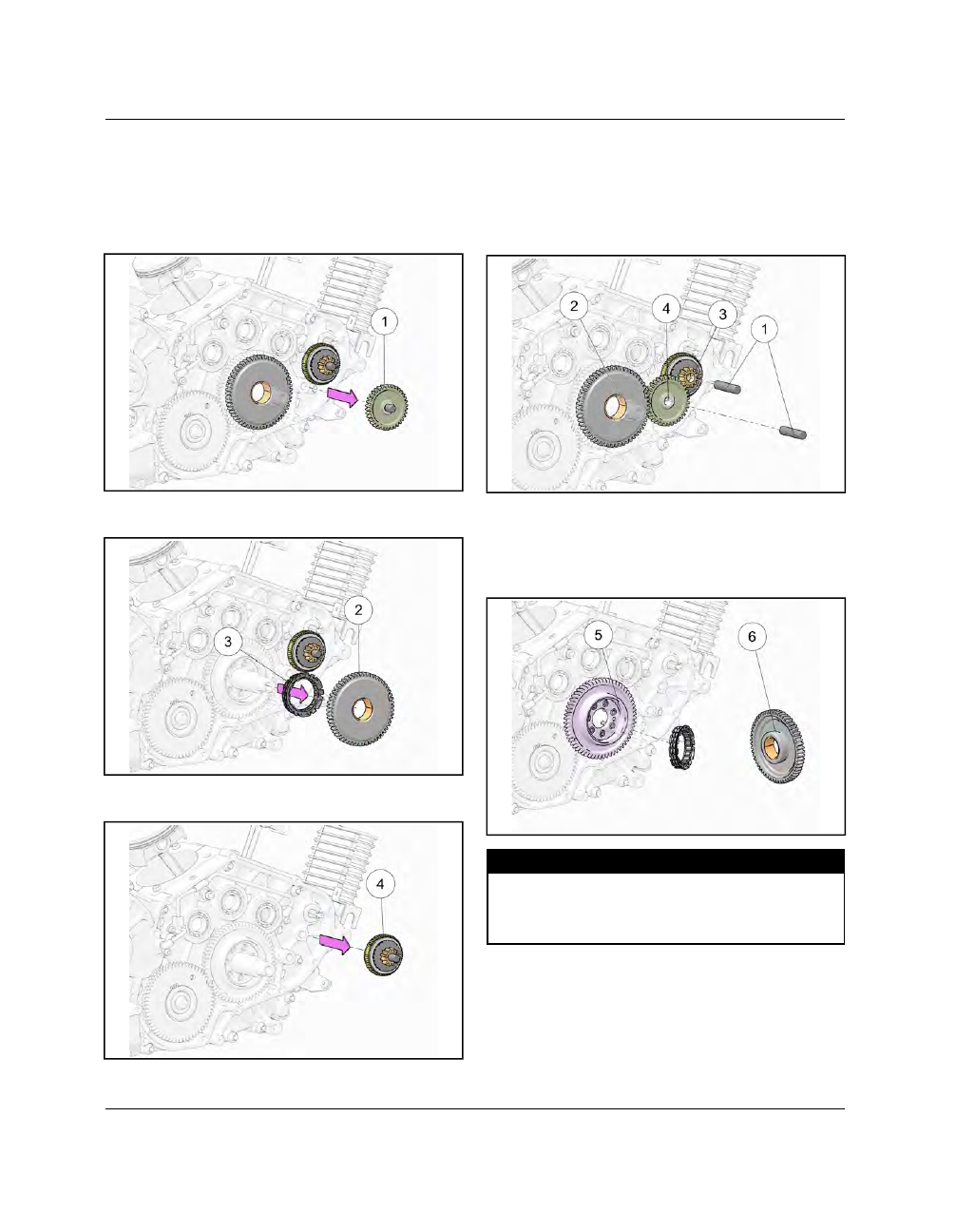
Remove the starter drive reduction gear

q

by

lifting the shaft and gear out as an assembly.

3.

Lift the sprag gear

w

and one-way clutch

e

off of

the crankshaft as an assembly.

4.

Remove the torque limiter clutch

r

and shaft as an

assembly.

SSTTAARRTTEERR DDRRIIVVEE IINNSSPPEECCTTIIOONN

1.

Inspect gear teeth for chips, cracks or excessive
wear.

2.

Inspect shaft surfaces

q

and bushing surfaces

w

e r

for excessive wear and scoring.

3.

Inspect one-way clutch hub surfaces

t y

for

wear, scoring or damage.

4.

Measure the I.D of the balance shaft gear bearing
surface

t

and the O. D. of the flywheel bearing

surface

y

and compare to specification.

MEASUREMENT

One-Way Clutch Hub I.D. (Balance Shaft Gear):

68.38

mm

±

.013 mm

One-Way Clutch Hub O.D. (Flywheel):

51.71 mm

±

.007 mm

5.

Replace gear if wear or damage is evident.

TRANSMISSION / CRANKSHAFT

6

6.21

SSTTAARRTTEERR DDRRIIVVEE IINNSSTTAALLLLAATTIIOONN

1.

NOTE

Install starter clutch so the arrow is facing out.

Install one-way starter clutch bearing

q

into the

balance shaft gear hub.

2.

Install flywheel

w

over crankshaft and into the

one-way clutch bearing until fully seated.

3.

Install the torque limiter shaft

e

into the crankcase

bore followed by the limiter clutch assembly

r

.

4.

NOTE

If previously removed, install starter motor at this

time.

Install the starter reduction gear shaft

t

into

crankcase bore followed by the reduction gear

y

.

The raised shoulder on the reduction gear
should face the crankcase.

TRANSMISSION / CRANKSHAFT

6.22

9927618 R03 - 2017 Indian Motorcycle (Full-Size) Service Manual

5.

Install spacer

u

onto the crankshaft.

6.

Install inner cam chain cover. See Inner Cam
Chain Cover Installation, page 6.19.

7.

Check engine oil and fill to proper level.

TRANSMISSION / CRANKSHAFT

6

6.23

CCRRAANNKKSSHHAAFFTT SSEERRVVIICCEE

CCRRAANNKKCCAASSEE SSEEPPAARRAATTIIOONN

1.

Drain engine oil. See Engine Oil / Filter Change,
page 2.9.

2.

Remove

engine

from

frame.

See

ENGINE

REMOVAL.

3.

Mount engine securely on an engine stand using
Engine Stand Adapter tool

PF-51240

.

4.

Remove cylinder heads. See Cylinder Head
Removal, page 3.61.

5.

Remove cylinders. See Cylinder Removal, page
3.76.

6.

Remove lifters. See Lifter Removal, page 3.45.

7.

Remove

primary

cover.

See

Primary

Cover

Removal, page 5.7.

8.

Remove

torque

compensator.

See

Torque

Compensator Removal, page 5.20.

9.

Remove clutch assembly. See Clutch Removal,
page 5.14.

10. Remove flywheel. See Flywheel Removal, page

5.22.

11. Remove stator. See Stator Removal, page 10.30.

12. Remove the cam chain. See Cam Chain Removal,

page 3.43.

13. Remove camshaft carrier assembly. See Camshaft

Carrier Removal, page 3.47.

14. Remove the inner cam chain cover. See Inner Cam

Chain Cover Removal, page 6.16.

15. Remove the starter drive. See Starter Drive

Removal, page 6.20.

16. Remove the balance shaft driven gear and drive

gear. See Balance Shaft Removal, page 6.16.

17. Remove the drive sprocket. See Drive Sprocket

Removal, page 8.48.

18. Remove the gear position switch. See Sensors —

Powertrain Management, page 4.12.

NOTE

Collect the two switch contact pins and springs from

the end of the shift drum so they do not get lost.

19. Remove engine case fasteners.

20. Place the Engine Case Splitting / Assembly tool

PF-51234

on a flat surface and assemble the M6

threaded spacers

q

and M12 threaded spacer

w

into the main plate

e

as shown.

Use only holes

marked with the letter A.

21. Rotate the engine stand so the engine is lying flat

with the output shaft pointing UP.

TRANSMISSION / CRANKSHAFT

6.24

9927618 R03 - 2017 Indian Motorcycle (Full-Size) Service Manual

22. Position the main plate assembly

r

onto the

engine case as shown. The threaded spacers
should line up with the corresponding engine case
fastener holes.

23. Install the case splitting adapter through the

center hole in the main plate and thread into nut
and washer

t

until 1– 2 threads are exposed on

the other side.

24.

Main plate adjustment: Turn threaded spacers
in or out to raise, lower and level the main
plate.

IMPORTANT

• Plate surface should be parallel to the surface of

the engine crankcase.

• Plate height is correct when the plate is resting on

the washer and the case splitting adapter contacts
the transmission output shaft.

• All threaded spacers must be in contact with

engine case prior to fastening on the plate
assembly.

25. Install M6 fasteners

y

and M12 fastener

u

into

threaded spacers and torque to specification.

TORQUE

Main Plate Mounting Fasteners (All):

88 in-lbs (10

Nm)

TRANSMISSION / CRANKSHAFT

6

6.25

26. Holding nut

i

stationary with an open ended

wrench, turn the case splitting adapter clockwise
until the engine cases begin to part.

STOP.

27. Using a soft-faced mallet, work around the seam of

the engine cases tapping lightly to release the
sealed bond.

28. Alternately turn the case splitting tool in until

resistance is felt, then work around the upper case
with a mallet until the cases are completely apart.

TRANSMISSION / CRANKSHAFT

6.26

9927618 R03 - 2017 Indian Motorcycle (Full-Size) Service Manual

TTRRAANNSSM

MIISSSSIIOONN RREEM

MOOVVAALL

CAUTION

Gloves should be worn at all times while working on

the transmission assembly to avoid personal injury.

1.

Remove the shift ratchet assembly. See Shift
Ratchet Removal & Inspection, page 5.9.

2.

Remove the balance shaft. See Balance Shaft
Removal, page 6.16.

3.

Lift both of the shift fork rails

q

out of the

crankcase just enough so the ends clear the
crankcase bores. Rotate rails and forks away from
the shift drum.

4.

Lift the shift drum

w

out of the bearing.

5.

As an assembly

, lift the input shaft

e

, output shaft

r

, shift forks and shift fork rails

t

out of the

engine case.

TRANSMISSION / CRANKSHAFT

6

6.27

TTRRAANNSSM

MIISSSSIIOONN IINNSSPPEECCTTIIOONN

Input Shaft

NUMBER

MEASUREMENT LOCATION

DIAMETER SPECIFICATION

q

Gear, 5th — I.D.

39.010 — 39.026 mm

w

Bushing, 5th Gear — O.D.

38.955 — 38.980 mm

e

Bushing, 5th Gear — I.D.

32.010 — 32.035 mm

r

Input Shaft, Clutch Collar Journal

29.470 — 29.485 mm

t

Input Shaft, Bearing Journal
(Primary Side)

29.976 — 29.990 mm

y

Gear, 6th — I.D.

39.010 — 39.026 mm

u

Bushing, 6th Gear — O.D.

38.955 — 38.980 mm

i

Input Shaft, 2nd Gear Journal
(Press Fit)

27.987 — 28.0 mm

o

Gear, 2nd — I.D. (Press Fit)

27.884 — 27.909 mm

TRANSMISSION / CRANKSHAFT

6.28

9927618 R03 - 2017 Indian Motorcycle (Full-Size) Service Manual

Output Shaft

NUMBER

MEASUREMENT LOCATION

DIAMETER SPECIFICATION

q

Gear, 2nd — I.D.

39.010 — 39.026 mm

w

Bushing, 2nd Gear — O.D.

38.955 — 38.980 mm

e

Bushing, 2nd Gear — I.D.

32.010 — 32.035 mm

r

Gear, 4th — I.D.

39.010 — 39.026 mm

t

Bushing, 4th Gear — O.D.

38.955 — 38.980 mm

y

Gear, 3rd — I.D.

39.010 — 39.026 mm

u

Output Shaft, Bearing Journal (Drive Sprocket
Side)

34.995 — 35.008 mm

i

Bushing, 3rd Gear — O.D.

38.955 — 38.980 mm

o

Gear, 1st— I.D.

37.010 — 37.026 mm

a

Bushing, 1st Gear — I.D.

28.015 — 28.040 mm

s

Bushing, 1st Gear — O.D.

36.965 — 36.990 mm

d

Output Shaft, 1st Gear Journal

27.987 — 28.0 mm

TRANSMISSION / CRANKSHAFT

6

6.29

NOTE

Refer to the Assembly View section in this chapter

for component locations and exploded diagrams.

See Crankcase, page 6.6ASSEMBLY VIEWS,

page

.

Refer to the Service Specifications section in this

chapter for complete transmission specifications.

See Service Specifications, page 6.4.

Shafts

1.

Measure outside diameter of shafts and bearing
areas for wear and concentricity. Look closely at
splines for wear. Inspect ends of shafts for signs of
wear:

• Dull finish
• Discoloration
• Rough or uneven surface
• Measurement outside of specification

Gears

2.

Visually inspect:

• Gear internal splines
• Gear teeth
• Gear dogs for rounding, cracks, chips
• Gear dog slots for rounding
• Bearing surfaces
• Shift fork grooves

Check each gear for damage, cracks, wear
(rounding of dogs or surfaces), or discoloration.

Shift Forks, Shift Fork Rails

3.

Inspect all contact surfaces of each shift fork.
Replace a shift fork if any part is discolored
(overheated), unusually scored, warped, or worn
beyond service limit.

4.

Inspect each shift fork pin for wear or damage and
compare to specifications.

5.

Inspect shift fork rails for wear, scoring, or runout.

6.

Measure shift fork rail O. D. for wear in 3 or 4
places along the length. The rail O. D. should be
consistent over the entire length.

7.

Slide rails into crankcase holes and check for a
good snug fit.

8.

Visually inspect the shift drum bearing in the left
crankcase for wear or damage. The bearing must
be fully seated in the case and held in position by
the retaining plate. Replace the bearing if it is
loose in the bore, or if any side play is detected.

9.

Temporarily install shift drum into bearing and
rotate, checking for smooth bearing operation.

Shift Drum

10. Inspect shift drum grooves for wear. Pay close

attention to corners of grooves where forks change
direction.

11. Inspect surface of shift drum star for excessive

wear or damage.

12. Inspect right side shift drum bearing.

13. Temporarily install shift drum in right hand case

bearing and inspect fit. Spin drum to check for
smooth bearing operation.

CCRRAANNKKSSHHAAFFTT RREEM

MOOVVAALL

1.

Separate

RH

crankcase

from

LH

case.

See

Crankcase Separation, page 6.23.

2.

Rotate balance shaft

q

until counterweights are

clear of crankshaft.

3.

Lift crankshaft assembly

w

straight up until clear

of case.

NOTE

Connecting rod bearings and main bearings are

easily damaged. Be careful not to cause damage to

these parts when servicing items within the

crankcase.

TRANSMISSION / CRANKSHAFT

6.30

9927618 R03 - 2017 Indian Motorcycle (Full-Size) Service Manual

CCOONNNNEECCTTIINNGG RROODD SSIIDDEE CCLLEEAARRAANNCCEE

IINNSSPPEECCTTIIOONN

1.

Move connecting rods to one side of crankshaft.
Insert a feeler gauge

q

between one connecting

rod and the crankshaft. Compare measurement to
specification outlined in this chapter. See Service
Specifications, page 6.4.

2.

If clearance recorded exceeds service limit, the
crankshaft, connecting rod or both must be
inspected

and

worn

parts

replaced.

See

Crankshaft Inspection, page 6.34.

CCOONNNNEECCTTIINNGG RROODD RREEM

MOOVVAALL // IIDDEENNTTIIFFIICCAATTIIOONN

NOTE

The connecting rod caps are marked with paint from

the factory, however it is recommended that an

additional reference mark be added for clarity.

Caps

are matched to rods and MUST be installed with

the proper orientation left to right and front to

back.

DO NOT strike or stamp the connecting rod.

1.

Use a permanent marker to mark orientation of
connecting rods and rod bearing caps.

These

parts MUST be installed in their original
locations.

EXAMPLE: Right connecting rod must

be assembled on the right side with the bearing
cap that was removed from it. The bearing cap and
connecting rod must be assembled in the same
direction as it was removed using the

same

fastener.

2.

Mark the outside of both connecting rods prior to
removal so they can be assembled in the same
direction in relation to the crankshaft.

3.

Remove connecting rod fasteners and connecting
rod bearing caps.

NOTE

It may be necessary to lightly tap the caps with a

plastic mallet to loosen them.

CAUTION

The mating surface of connecting rod and cap is

rough in appearance, which is a normal condition

due to the manufacturing process. If rod caps are

installed

incorrectly

and tightened, the precision

mating surfaces will be damaged. Replace the

connecting rod assembly if mating surfaces are

damaged.

TRANSMISSION / CRANKSHAFT

6

6.31

CCOONNNNEECCTTIINNGG RROODD IINNSSPPEECCTTIIOONN ((BBIIGG EENNDD))

IMPORTANT

Connecting rod fasteners can only be reused

three times.

Failure to replace fasteners after

completing three torque sequences may result in

severe engine damage. Each time a fastener has

been torqued to specification, it should be marked

with a center punch.

EXAMPLE:

• 1st Torque: Manufacturer installation of connecting

rod fasteners.

• 2nd Torque: Torque for inspection per this

procedure.

• 3rd Torque: Reinstallation following inspection.

Discard fasteners the next time they are
removed.

1.

Refer to Piston Pin / Pin Bore Inspection, page 3.80
for connecting rod small end inspection.

CAUTION

Be sure to match connecting rod caps with their

respective rod and orient the cap properly before

installing the cap. Secure the big end of rods in a vise

equipped with soft, protective jaws before torquing

rod fasteners.

2.

Remove bearings and install caps on connecting
rods. Be sure mating surfaces

q

of rod and cap are

clean.

3.

Apply engine oil to threads of rod fasteners.
Torque fasteners to specification.

TORQUE

Connecting Rod Fasteners:

22 ft-lbs (30 Nm)

4.

Measure I. D. of connecting rod big end for size
and out of round and compare to specification. See
Service Specifications, page 6.4.

5.

Visually inspect connecting rod upper and lower
ends for scoring, damage, or excessive wear.

CCOONNNNEECCTTIINNGG RROODD BBEEAARRIINNGG IINNSSPPEECCTTIIOONN

1.

Inspect bearing inserts for unusual wear, peeling,
scoring, damage etc. Replace as a set if damage is
noted. Inspect bearing clearance and refer to
Bearing Selection Chart. See Connecting Rod
Bearing Selection, page 6.33.

CCOONNNNEECCTTIINNGG RROODD BBEEAARRIINNGG CCLLEEAARRAANNCCEE

IINNSSPPEECCTTIIOONN

1.

Assemble the connecting rod cap with bearings
and torque to specification.

TORQUE

Connecting Rod Fasteners:

22 ft-lbs (30 Nm)

TRANSMISSION / CRANKSHAFT

6.32

9927618 R03 - 2017 Indian Motorcycle (Full-Size) Service Manual

2.

Measure the connecting rod big end bearing I. D.
with a dial bore gauge and record.

3.

Measure the connecting rod journal on crankshaft
and record.

4.

Subtract the journal diameter from the connecting
rod bearing diameter to calculate oil clearance
and

compare

to

specification.

See

Service

Specifications, page 6.4.

5.

If service limits are exceeded, install new rod
bearings and recheck oil clearance.

6.

If service limits are still exceeded, determine if
crankshaft

or

connecting

rods

need

to

be

replaced.

TRANSMISSION / CRANKSHAFT

6

6.33

CCOONNNNEECCTTIINNGG RROODD BBEEAARRIINNGG SSEELLEECCTTIIOONN

1.

There are 3 sizes of connecting rod bearings
available: Black, Orange and Blue (see chart
below).

2.

To determine which bearing to use, look at the
color code on RH end of crankshaft. “R” for Red
and “W” for White. The letter will be stamped
onto the counterweight.

3.

The color code on the connecting rod appears in
the form of a painted mark on the side facing away
from the center of the crankshaft.

4.

Refer to the chart below to select the proper
bearing insert.

FOR EXAMPLE: If the CONNECTING ROD paint
mark is RED and the CRANKSHAFT stamp is W
(white) (or not stamped), use BLUE bearing
inserts.

CONNECTING ROD BEARING SELECTION CHART

Connecting Rod Color

Crankshaft Color

Bearing Color

(P/N 3514790

-

xxx

)

Bearing Thickness

WHITE Paint Mark

RED (“R” Stamp)

Black (

- 067

)

1.474 — 1.479 mm

WHITE Paint Mark

WHITE (“W” Stamp
or not marked)

Orange (

- 159

)

1.478 — 1.483 mm

RED Paint Mark

RED (“R” Stamp)

Orange (

- 159

)

RED Paint Mark

WHITE (“W” Stamp
or not marked)

Blue (

- 027

)

1.482 — 1.488 mm

TRANSMISSION / CRANKSHAFT

6.34

9927618 R03 - 2017 Indian Motorcycle (Full-Size) Service Manual

CCRRAANNKKSSHHAAFFTT IINNSSPPEECCTTIIOONN

Record

all

measurements

and

compare

to

specifications. Replace crankshaft if any measurement
is worn beyond the service limit. See Service
Specifications, page 6.4.

1.

Measure the width of the rod bearing journal.

2.

Measure width of connecting rods at big end.

3.

Visually inspect all bearing journals for scoring,
damage or excessive wear.

4.

Crankshaft and connecting rods are identified by
color. Be sure to compare measurements to
specifications for the proper color (or non-
marked) connecting rod or crankshaft.

Measure O. D. of crankshaft rod journal in four
places and compare to specifications.

5.

Measure O.D. of main bearing journals.

CCOONNNNEECCTTIINNGG RROODD IINNSSTTAALLLLAATTIIOONN

1.

Make sure proper bearing clearance is achieved
by using the correct colored bearing insert for a
given color combination of connecting rod and
crankshaft.

2.

Clean all oil off connecting rod, connecting rod
cap and bearing inserts.

3.

Install bearing inserts into connecting rods and
caps. First, install bearing tab into groove, then
press the rest of the bearing into place.

NOTE

Procedure during disassembly called for marking of

connecting rods and caps. Ensure that each part is

installed in original location including rod cap

fasteners.

4.

Apply assembly lube to connecting rod bearings
and crank pin.

5.

Install

rods

and

caps

onto

the

crankshaft,

observing the paint mark on the connecting rods.

The paint mark must face away from the center
of the crankshaft.

Be sure the identifier marks

made previously are aligned.

6.

Tighten rod cap fasteners:

TORQUE

Connecting Rod Fasteners:

22 ft-lbs (30 Nm)

7.

Check that the connecting rods rotate smoothly
and freely on crankshaft journal.

TRANSMISSION / CRANKSHAFT

6

6.35

CCRRAANNKKSSHHAAFFTT CCLLEEAANNIINNGG

1.

Remove blind plug

q

from crankshaft to ensure

that passages are clear.

2.

After cleaning passages, install blind plug and
torque to specification. Plug should be flush with
surface of crankshaft.

TORQUE

Blind Plug:

15 ft-lbs (20 Nm)

M

MAAIINN BBEEAARRIINNGG IINNSSPPEECCTTIIOONN

1.

Inspect crankcase main bearing surfaces

q

&

w

for wear, peeling, scoring, or damage.

2.

Inspect alignment of bearing lubrication hole in
left crankcase half and in right case half. Holes
must be aligned with their respective oil passage
in crankcase.

M

MAAIINN BBEEAARRIINNGG OOIILL CCLLEEAARRAANNCCEE IINNSSPPEECCTTIIOONN

1.

Measure main bearing I. D. and concentricity with
a dial bore gauge for right and left side. Compare
to specification. Subtract crankshaft main journal
diameter from main bearing diameter to calculate
oil clearance. See Service Specifications, page 6.4.

2.

If crankshaft dimensions are within tolerances and
oil clearances are incorrect, the crankcase set
must be replaced or new main bearings installed
and line-honed by a competent machinist.

NOTE

Replace crankcase halves as a set.

TRANSMISSION / CRANKSHAFT


Content      ..     18      19      20      21     ..