Indian motorcycle 2017. Service Manual - page 19


  Главная      Manuals     Indian motorcycle 2017. Service Manual


Search            copyright infringement  


Content      ..     17      18      19      20     ..


Indian motorcycle 2017. Service Manual - page 19


6.4

9927618 R03 - 2017 Indian Motorcycle (Full-Size) Service Manual

SSEERRVVIICCEE SSPPEECCIIFFIICCAATTIIOONNSS

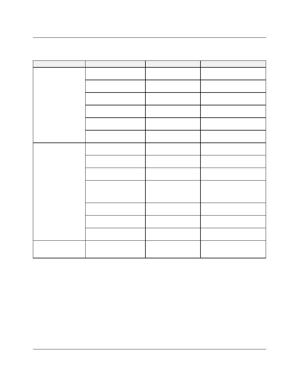
Connecting Rod / Crankshaft Specifications

PART

PART SPECIFIC

STANDARD

SERVICE LIMIT

Connecting Rod

Connecting Rod to
Crankshaft Side Clearance

.22 - .42 mm
(.0087 - .0165")

.65 mm (.025")

Connecting Rod Bearing to
Crankshaft Oil Clearance

.0254 - .0635 mm
(.001 - .0025")

.11 mm (.0043")

Connecting Rod Small End
I.D.

22.01 - 22.02 mm
(.8665 - .8670")

22.09 mm (.8694")

Connecting Rod Width

21.01 - 21.11 mm
(.8271 - .8310")

20.76 mm (.8173")

Connecting Rod Big End
I.D. (White)

54.992 - 55.000 mm
(2.1650 - 2.1653")

55.030 mm (2.1665")

Connecting Rod Big End
I.D. (Red)

55.000 - 55.008 mm
(2.1653 - 2.1656")

55.038 mm (2.1668")

Crankshaft Main
Bearing / Rod Journals

Connecting Rod Journal
Width

42.42 - 42.50 mm
(1.670 - 1.673")

43.46 mm (1.627")

Crankshaft Rod Journal
O.D. (White)

51.9920 - 51.9999 mm
(2.0469 - 2.0472")

51.9620 mm (2.0457")

Crankshaft Rod Journal
O.D. (Red)

52.0000 - 52.0080 mm
(1.8888 - 1.8891")

51.970 mm (2.0460")

Main Bearing Oil
Clearance

Left .013 - .060 mm
(.0005 - .0023")
Right .014 - .061mm
(.0005 - .0024")

.10 mm (.004")

Left Main Bearing Journal
O.D.

59.9523 - 59.9703 mm
(2.3603 - 2.3610")

59.9323 mm (2.3595")

Right Main Bearing Journal
O.D.

64.9523 - 64.9703 mm
(2.5571 - 2.5578")

64.9273 mm (2.5561")

Crankshaft End Play

.05 - .30 mm
(.0019 - .0118")

-

Balance Shaft

Journal O.D., Left (Primary
Side) / Journal O.D., Right
(Cam Side)

24.980 - 24.992 mm /
24.969 - 24.979 mm

-

TRANSMISSION / CRANKSHAFT

6

6.5

Transmission Specifications

ITEM

PART SPECIFIC

STANDARD

SERVICE LIMIT

Shift Fork

Shift Fork I.D. (Rail)

12.00 - 12.026 mm

(.4725 - .4732")

12.05 mm (.4744")

Shift Fork Pin O.D.

6.036 - 6.136 mm

(.2376 - .2416")

6.02 mm (.2370")

Shift Fork Rail

Shift Fork Rail O.D.

11.948 - 11.972 mm

(.4704 - .4713")

11.92 mm (.4693")

Shift Fork Rail Runout

-

.025 mm (.001")

Shift Drum

Shift Drum Groove

-

Replace drum if any wear
is evident

ITEM

SPECIFICATIONS

Drive Train (General)

Transmission

6 Speed (Overdrive)

Primary Reduction Ratio

1.56: 1

Final Reduction Ratio

2.2: 1

Drive Train (Gear Ratios)

Gear Ratio: 1st Gear

2.73: 1

Gear Ratio: 2nd Gear

1.86: 1

Gear Ratio: 3rd Gear

1.38: 1

Gear Ratio: 4th Gear

1.10: 1

Gear Ratio: 5th Gear

.94: 1

Gear Ratio: 6th Gear (Overdrive)

0.81: 1

TRANSMISSION / CRANKSHAFT

6.6

9927618 R03 - 2017 Indian Motorcycle (Full-Size) Service Manual

AASSSSEEM

MBBLLYY VVIIEEW

WSS

CCRRAANNKKCCAASSEE

NUMBER

PART DESCRIPTION

TORQUE (IF APPLICABLE)

q

Fastener, Crankcase — M8 x 1.25 x 100 (QTY.12)

22 ft-lbs (30 Nm)

w

Fastener, Crankcase — M8 x 1.25 x 110 (QTY.6)

22 ft-lbs (30 Nm)

e

Bearing, Camshaft

r

Fastener, Bearing Retainer – M5 x 0.8 x 12 (QTY.16)

62 in-lbs (7 Nm)

t

Retainer Plate, Bearing

y

Bearing, Balance Shaft

u

Bearing, Crankshaft (Camshaft Side) — Non-Serviceable

i

Crankcase, RH

o

Fastener, Piston Cooling Jet — M5 x 0.8 x 10 (QTY.2)

62 in-lbs (7 Nm)

a

Bearing, Transmission Output Shaft

s

Retainer Plate, Bearing

d

Bearing, Shift Drum

f

Bearing, Transmission Input Shaft

g

Retainer Plate, Bearing

h

Bearing, Shift Drum

j

Bearing, Crankshaft (Primary Side) — Non-Serviceable

k

Bearing, Transmission Input Shaft

l

Crankcase, LH

1(

Bearing, Shift Shaft

TRANSMISSION / CRANKSHAFT

6

6.7

CCRRAANNKKSSHHAAFFTT

NUMBER

PART DESCRIPTION

TORQUE (IF APPLICABLE)

q

Bearing, Crankshaft Main (RH) — Non-Serviceable

w

Fastener, Connecting Rod Bearing Cap (QTY.4)

22 ft-lbs (30 Nm)

e

Bearing Caps, Connecting Rod

r

Bearings, Connecting Rod (big end)

t

Piston

y

Tone Ring, Crankshaft Position Sensor — Non-
Serviceable

u

Fastener, Tone Ring - M8 x 1.25 x 16 (QTY.3)

18 ft-lbs (24 Nm)

i

Bearing, Crankshaft Main (LH) — Non-Serviceable

o

Wrist Pin, Piston

a

Circlip, Wrist Pin

TRANSMISSION / CRANKSHAFT

6.8

9927618 R03 - 2017 Indian Motorcycle (Full-Size) Service Manual

CCRRAANNKKCCAASSEE FFAASSTTEENNEERR LLEENNGGTTHH AANNDD TTOORRQQUUEE

PPAATTTTEERRNN

NOTE

Items 1, 3, 4, 11, 13 & 15 use Long fasteners. All other

items use Short fasteners.

Torque case fasteners to specification following the
torque sequence.

TORQUE

Crankcase Fasteners:

22 ft-lbs (30 Nm)

TRANSMISSION / CRANKSHAFT

6

6.9

TTRRAANNSSM

MIISSSSIIOONN

Input Shaft

NUMBER

DESCRIPTION

q

Input Shaft, Transmission

w

Gear, 5th — Drive

e

Bearing, 5th Gear

r

Bearing, 6th Gear

t

Slider, Gear Dog

y

Gear Dog, 5th & 6th

u

Gear, 6th — Drive

i

Gear, 4th — Drive

o

Gear, 2nd — Drive

a

Snap Ring

TRANSMISSION / CRANKSHAFT

6.10

9927618 R03 - 2017 Indian Motorcycle (Full-Size) Service Manual

Output Shaft

NUMBER

DESCRIPTION

q

Snap Ring

w

Spacer

e

Gear, 1st — Driven

r

Bearing, 1st Gear

t

Slider, Gear Dog

y

Gear Dog

u

Gear, 3rd — Driven

i

Bearing

o

Gear, 5th — Driven

a

Gear, 6th — Driven

s

Gear, 4th — Driven

d

Gear, 2nd — Driven

f

Bearing, 2nd Gear

g

Output Shaft, Transmission

TRANSMISSION / CRANKSHAFT

6

6.11

SSHHIIFFTT DDRRUUM

M // SSHHIIFFTT FFOORRKK

NUMBER

DESCRIPTION

q

Bearing, Shift Drum — Drive Sprocket Side

w

Gear Dog

e

Slider, Gear Dog

r

Shift Fork, 5th & 6th

t

Shift Rail

y

Bearing, Shift Drum — Primary Side

u

Shift Fork, 1st & 3rd

i

Shift Fork, 2nd & 4th

o

Shift Drum

TRANSMISSION / CRANKSHAFT

6.12

9927618 R03 - 2017 Indian Motorcycle (Full-Size) Service Manual

BBAALLAANNCCEE SSHHAAFFTT

NUMBER

PART DESCRIPTION

TORQUE (IF APPLICABLE)

q

Fastener, Balance Shaft Gear — M10 x 1.5 x 40
(QTY.1)

59 ft-lbs (80 Nm)

w

Washer

-

e

Snap-Ring, Balance Shaft Split Gear

-

r

Gear, Balance Shaft (Outer) — Non-Serviceable

-

t

Springs, Pre-Load — Non-Serviceable

-

y

Gear, Balance shaft (Inner) — Non-Serviceable

-

u

Fastener, Bearing Retainer Plate — M5 x 0.8 x 12
(QTY.3)

62 in-lbs (7 Nm)

i

Bearings, Balance Shaft

-

o

Balance Shaft

-

TRANSMISSION / CRANKSHAFT

6

6.13

GGEEAARR TTRRAAIINN

1st Gear

2nd Gear

TRANSMISSION / CRANKSHAFT

6.14

9927618 R03 - 2017 Indian Motorcycle (Full-Size) Service Manual

3rd Gear

4th Gear

TRANSMISSION / CRANKSHAFT

6

6.15

5th Gear

6th Gear

TRANSMISSION / CRANKSHAFT

6.16

9927618 R03 - 2017 Indian Motorcycle (Full-Size) Service Manual

BBAALLAANNCCEE SSHHAAFFTT SSEERRVVIICCEE

IINNNNEERR CCAAM

M CCHHAAIINN CCOOVVEERR RREEM

MOOVVAALL

1.

Remove

the

camshaft

carrier

assembly.

See

Camshaft Carrier Removal, page 3.47.

2.

Remove inner cam chain cover fasteners

q

and

inner cam chain cover

w

.

BBAALLAANNCCEE SSHHAAFFTT RREEM

MOOVVAALL

1.

Remove the inner cam cover. See Inner Cam Chain
Cover Removal, page 6.16.

2.

Remove the fastener

q

and balance shaft gear

w

.

IMPORTANT

Be sure to collect the woodruff key from the end of

the balance shaft once the gear has been removed.

3.

Separate

the

engine

cases.

See

Crankcase

Separation, page 6.23.

4.

Rotate balance shaft

e

until counterweights are

clear of crankshaft. Grasp balance shaft and
remove it from case.

5.

Inspect sprocket teeth for wear or damage.

6.

Check shaft for runout, or twisting.

7.

Rotate right and left balance shaft bearings by
hand while observing bearing rotation. Bearings
should run smooth and quiet and shaft should be a
snug fit in bearing.

8.

Visually inspect bearings for damage.

TRANSMISSION / CRANKSHAFT

6

6.17

BBAALLAANNCCEE SSHHAAFFTT IINNSSTTAALLLLAATTIIOONN

1.

Lubricate balance shaft bearings with engine oil.

2.

Insert the balance shaft

q

into the primary side

bearing until fully seated. Woodruff key slot
should be facing the cam side of the engine.

3.

Assemble

the

engine

cases.

See

Crankcase

Assembly, page 6.39.

4.

Lock the crankshaft for service using

Method 1.

See Locking the Crankshaft for Service, page 3.41.

5.

Install the balance shaft drive gear and torque
fasteners

w

to specification.

TORQUE

Balance Shaft Drive Gear:

10 ft-lbs (14 Nm)

6.

Place the woodruff key into the end of the balance
shaft.

7.

Place a pin punch, or other suitable tool, through
hole

e

and preload split gear teeth so they are

aligned.

8.

Fit the driven balance shaft gear to the end of the
balance shaft so the timing marks

r

are aligned as

shown.

9.

Thread the driven balance shaft gear fastener

t

in

until seated.

10. Torque the driven balance shaft gear fastener to

specification.

TORQUE

Balance Shaft Driven Gear:

59 ft-lbs (80 Nm)

11. Install

the

starter

drive.

See

Starter

Drive

Installation, page 6.21.

TRANSMISSION / CRANKSHAFT

6.18

9927618 R03 - 2017 Indian Motorcycle (Full-Size) Service Manual

12. Install the spacer

y

onto the crankshaft.

13. Install the inner cam cover. See Inner Cam Chain

Cover Installation, page 6.19.

TRANSMISSION / CRANKSHAFT

6

6.19

IINNNNEERR CCAAM

M CCHHAAIINN CCOOVVEERR IINNSSTTAALLLLAATTIIOONN

1.

Clean inner cam chain cover and crankcase
mating surfaces with a residue-free degreaser.

2.

Apply Loctite flange sealant

PN: 8560070

to cover

and assemble to crankcase.

3.

Thread inner cam chain cover fasteners into
crankcase so they are finger tight.

4.

Tighten inner cam chain cover fasteners following
the specified torque sequence.

TORQUE

Inner Cam Chain Cover Fasteners:

15 ft-lbs (20 Nm)

5.

Install

the

camshaft

carrier

assembly.

See

Camshaft Carrier Installation, page 3.53.

TRANSMISSION / CRANKSHAFT


Content      ..     17      18      19      20     ..