Indian motorcycle 2017. Service Manual - page 18


  Главная      Manuals     Indian motorcycle 2017. Service Manual


Search            copyright infringement  


Content      ..     16      17      18      19     ..


Indian motorcycle 2017. Service Manual - page 18


5.12

9927618 R03 - 2017 Indian Motorcycle (Full-Size) Service Manual

SSHHIIFFTT SSHHAAFFTT BBEEAARRIINNGG &

& SSEEAALL RREEPPLLAACCEEM

MEENNTT

1.

Remove

primary

cover.

See

Primary

Cover

Removal, page 5.7.

2.

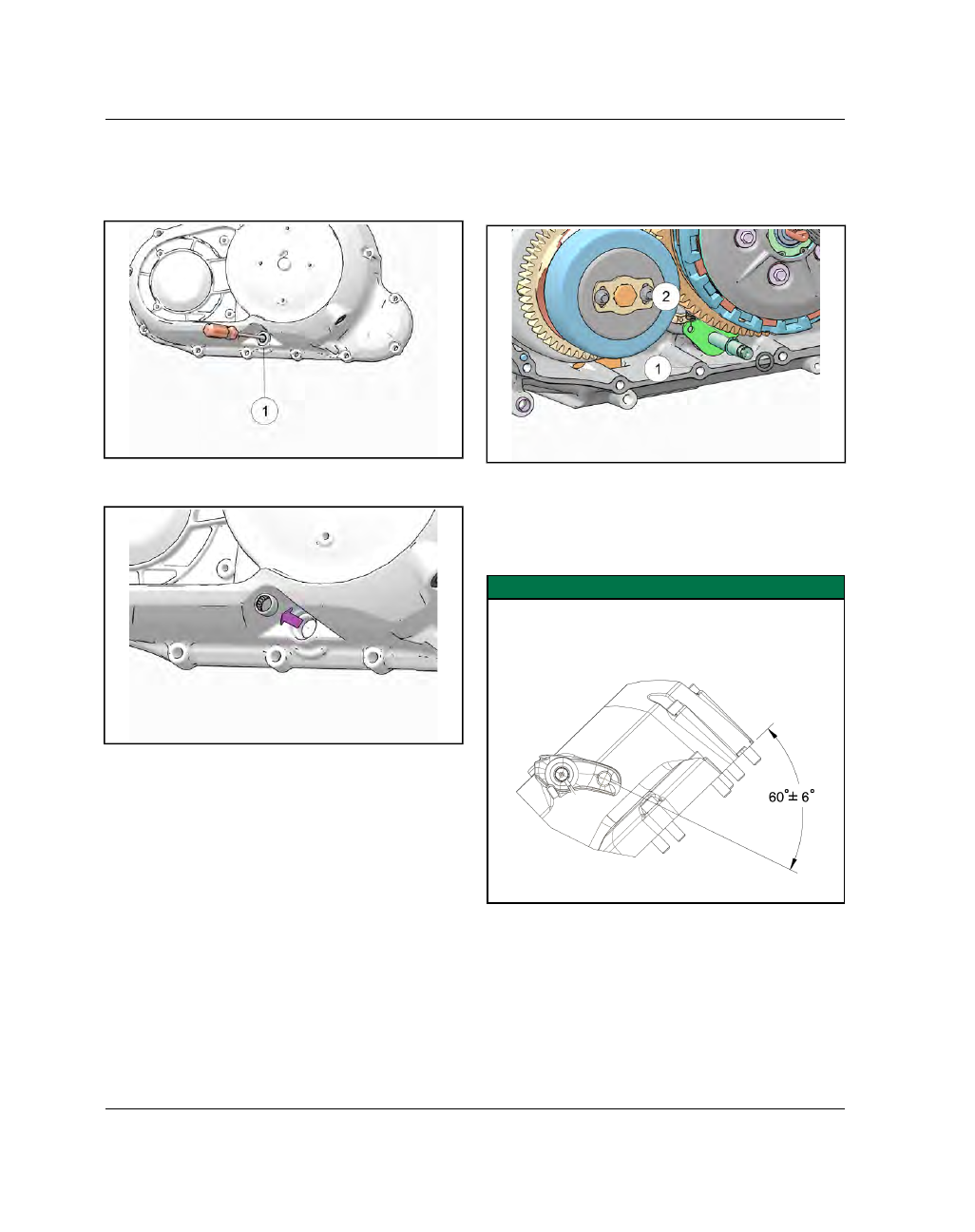
Carefully pry shift shaft seal

q

from cover.

3.

Using a suitable arbor and arbor press, press
bearing

w

from inside of cover to outside.

4.

Apply assembly lube to inner & outer surfaces of
new bearing.

Moly assembly paste PN: 2871460

5.

Press bearing into place with numbered side out
until fully seated.

6.

Apply a small amount of grease to lip of seal and
apply engine oil to outside of seal.

7.

Drive seal into place with a seal driver slightly
smaller than the O.D. of seal.

8.

Install

primary

cover.

See

Primary

Cover

Installation, page 5.12.

9.

After installing primary cover, be sure shift shaft
returns freely to the centered position after
rotating up or down.

PPRRIIM

MAARRYY CCOOVVEERR IINNSSTTAALLLLAATTIIOONN

1. Clean gasket surfaces of crankcase and cover.

2. Install the thrust washer

q

onto the shift shaft so it

rests on snap ring

w

.

3. Install a new primary cover gasket.

4. Apply a thin layer of grease to the shift shaft seal.

5. Install the primary cover so the clutch arm is

angled

correctly

and

install

primary

cover

fasteners so they are finger tight.

IMPORTANT

The clutch shaft must engage the clutch rack so that

the clutch arm is angled approximately 60° off of the

primary cover mating surface when fully seated.

CLUTCH / PRIMARY / SHIFT

5

5.13

6. Torque the primary cover fasteners to specification

following the torque sequence.

TORQUE

Primary Cover Fasteners:

15 ft-lbs (20 Nm)

Primary Cover Torque Sequence

CLUTCH / PRIMARY / SHIFT

5.14

9927618 R03 - 2017 Indian Motorcycle (Full-Size) Service Manual

CCLLUUTTCCHH SSEERRVVIICCEE

CCLLUUTTCCHH RRAACCKK,, RREEM

MOOVVAALL // IINNSSTTAALLLLAATTIIOONN

1.

Using an internal snap ring pliers, remove snap
ring

q

and clutch rack

w

.

2.

INSTALLATION:

Reverse the removal procedure

to install.

CCLLUUTTCCHH RREEM

MOOVVAALL

1.

Remove

primary

cover.

See

Primary

Cover

Removal, page 5.7.

2.

Remove clutch rack. See Clutch Rack, Removal /
Installation, page 5.14.

3.

Perform

the

crankshaft

locking

procedure

METHOD 2.

See Locking the Crankshaft for

Service, page 3.41.

4.

Remove clutch nut

q

, Belleville washer

w

, and

flat washer

e

. Discard the stake nut.

5.

Remove clutch assembly from clutch shaft.

6.

A new stake nut must be installed upon assembly.

CCLLUUTTCCHH DDIISSAASSSSEEM

MBBLLYY

CAUTION

Clutch is under spring pressure. WEAR EYE

PROTECTION.

1.

Remove the clutch. See Clutch Removal, page
5.14.

2.

Remove the sleeve

q

and needle bearing

w

from

the back side of the clutch assembly.

3.

With the clutch assembly resting on a clean, flat
work surface, alternately loosen the five pressure
plate fasteners

e

in a

star pattern

until spring

tension

has

relaxed.

Remove

fasteners

and

springs.

CLUTCH / PRIMARY / SHIFT

5

5.15

4.

Remove pressure plate

r

.

5.

Lift the clutch assembly

t

out of the basket and

set aside.

6.

Remove thrust washer

y

.

NOTE

The clutch assembly consists of three different

types of friction plates and two different types of

seperator plates. See Clutch, page 5.6.

PART DESCRIPTION

QUANTITY

Friction Plate A (TOP)

1

Friction Plate B (MIDDLE)

5

Friction Plate C (BOTTOM)

1

Seperator Plate A (TOP)

2

Seperator Plate B
(BOTTOM)

4

Spring, Judder Clutch

1

Seat, Judder Clutch

1

7.

Remove Friction Plate A

u

, Seperator Plate A

i

,

Friction Plate B

o

and Seperator Plate A

i

.

CLUTCH / PRIMARY / SHIFT

5.16

9927618 R03 - 2017 Indian Motorcycle (Full-Size) Service Manual

8.

Alternately remove Friction Plates B

a

and

Seperator Plates B

s

.

9.

Remove Friction Plate C

d

, Judder Spring

f

and

Judder Spring Seat

g

.

CCLLUUTTCCHH IINNSSPPEECCTTIIOONN

1.

Clean clutch plates, inner hub, and outer basket.

Clutch Basket

2.

Inspect clutch gear teeth

q

for wear, cracks or

damage.

3.

Inspect inside surfaces

w

of basket for cracks or

wear (grooves) from clutch plates.

4.

Replace parts that fail inspection

5.

Rotate hub bearing. Check for smooth rotation.
Inner race should have no detectable radial
movement.

6.

Lubricate bearing

e

with engine oil.

Clutch Hub

7.

Inspect spline teeth

r

for wear, cracks or damage.

CLUTCH / PRIMARY / SHIFT

5

5.17

8.

Inspect surface of steel plate guides

t

on outer

edge of hub for wear, grooves, or damage. Check
all posts

y

for cracks or damage.

9.

Visually inspect friction and steel plates for wear
or damage on both surfaces. Replace plates as a
set if any plate is worn or damaged.

10. Replace steel plates if grooved, distorted or

discolored. Inspect plates for distortion by placing
each plate on a precision flat surface. Insert a
feeler gauge between plate and flat surface in
several places.

MEASUREMENT

Clutch Steel Plate Warp Service Limit:

.008 in (.20

mm)

11. Measure thickness of friction plates in several

places. Thickness should be the same at each
place. Replace plates that fail inspection.

MEASUREMENT

Friction Plate Thickness (Minimum):

.126 in (3.2

mm)

Clutch Pressure Plate

12. Inspect pressure plate for cracks, scoring, or wear

on friction surface.

Clutch Springs

13. Inspect clutch springs for cracks or distortion.

Clutch Release Rack and Bearing

NOTE

Clutch rack is serviceable as an assembly only.

14. Inspect clutch rack for broken or damaged teeth.

15. Inspect lifter bearing visually for any signs or wear

or discoloration. Rotate bearing inner race with
your finger and check for smooth movement and
no play.

16. Replace clutch rack assembly if necessary.

CLUTCH / PRIMARY / SHIFT

5.18

9927618 R03 - 2017 Indian Motorcycle (Full-Size) Service Manual

CCLLUUTTCCHH AASSSSEEM

MBBLLYY

1.

Install the thrust washer

q

and the clutch hub

w

into the clutch basket.

2.

Apply engine oil to judder spring seat

e

and

spring

r

.

3.

Install judder spring seat (flat ring), then judder
spring.

NOTE

Judder spring must be installed with concave side

facing UP (toward outside of clutch). The tallest edge

of spring will be outermost.

4.

NOTE

Refer to the Clutch Assembly View outlined in

this chapter for clutch plate orientation. See

Clutch, page 5.6.

Apply engine oil to Friction Plate C

t

and install.

5.

Place an oiled Seperator Plate B into clutch basket.

NOTE

If friction plates are new, soak them in clean engine

oil for a few minutes before installing.

6.

Continue stacking oiled clutch plates into clutch
basket

alternating

Friction

Plate

B

y

and

Seperator Plate B

u

stopping at the fourth Friction

Plate B.

There should be one Friction Plate B

remaining.

7.

Install Seperator Plate A

i

followed by Friction

Plate B

o

and Seperator Plate A

i

.

8.

Install the final Friction Plate A

a

.

9.

Apply engine oil to hub bearing

s

.

CLUTCH / PRIMARY / SHIFT

5

5.19

10. Install the hub bearing and sleeve

d

into the

clutch assembly.

11. Install the pressure plate

f

and clutch springs and

fasteners

g

.

Alternately tighten the clutch

spring fasteners in a star pattern until fully
seated.

12. Torque clutch spring fasteners to specification.

TORQUE

Clutch Spring Fasteners:

89 in-lbs (10 Nm)

CCLLUUTTCCHH IINNSSTTAALLLLAATTIIOONN

1.

IMPORTANT

When installing clutch assembly on the input shaft,

make sure that the thrust washer between the clutch

basket and the clutch hub goes onto the shaft and

does not fall between hub and basket.

Slide the clutch assembly onto the transmission
input shaft until fully seated.

2.

Install washer

q

,

a new spring washer

w

w

and a

new stake nut

e

e

.

3.

Lock the crankshaft using

Method 2.

See Locking

the Crankshaft for Service, page 3.41.

4.

Torque the stake nut to specification.

TORQUE

Clutch Stake Nut:

125 ft-lbs (170 Nm)

5.

Install clutch rack assembly. See Clutch Rack,
Removal / Installation, page 5.14.

6.

Install

primary

cover.

See

Primary

Cover

Installation, page 5.12.

7.

Check engine oil and fill to proper level.

CLUTCH / PRIMARY / SHIFT

5.20

9927618 R03 - 2017 Indian Motorcycle (Full-Size) Service Manual

TTOORRQQUUEE CCOOM

MPPEENNSSAATTOORR SSEERRVVIICCEE

TTOORRQQUUEE CCOOM

MPPEENNSSAATTOORR RREEM

MOOVVAALL

1.

Remove

primary

cover.

See

Primary

Cover

Removal, page 5.7.

2.

Perform crankshaft locking procedure METHOD 2.
See Locking the Crankshaft for Service, page 3.41.

3.

Remove the two fasteners

q

, locking plate

w

,

torque

compensator

fastener

e

and

spring

retainer assembly

r

from the crankshaft.

4.

Remove the spring pack

t

, upper torque

compensator ramp

y

and torque compensator

drive gear

u

from the crankshaft.

TTOORRQQUUEE CCOOM

MPPEENNSSAATTOORR IINNSSPPEECCTTIIOONN

1.

Inspect all parts for excessive galling or damage.

NOTE

Some polishing will be evident between the

compensator gear and the compensator slider and is

a normal condition. Replace assembly if ramps are

worn.

2.

Measure free length of torque compensator spring
stack.

MEASUREMENT

Compensator Spring Stack Height:

1.437–1.476 in

(36.5–37.5 mm)

CLUTCH / PRIMARY / SHIFT

5

5.21

TTOORRQQUUEE CCOOM

MPPEENNSSAATTOORR IINNSSTTAALLLLAATTIIOONN

1.

Apply engine oil to shaft splines, sleeve, washer,
peaks,

valleys

and

sliding

ramps

before

installation.

2.

Install the splined sleeve

q

, flange side down,

over the crankshaft followed by thrust washer

w

.

3.

Install the torque compensator gear

e

and upper

ramp

r

.

4.

Load the three Belleville spring packs

t

into the

spring retainer cup

y

and fit the drive plate and

fastener

u

into the spring retainer cup.

5.

Slide the torque compensator spring assembly
onto the crankshaft until the drive plate splines are
fully seated.

6.

Lock the crankshaft for service using

Method 2

.

See Locking the Crankshaft for Service, page 3.41.

7.

Apply Loctite 262 to compensator fastener and
torque to specification.

TORQUE

Compensator Fastener:

83 ft-lbs (112 Nm)

8.

Install compensator locking plate and fasteners

i

and torque to specification.

TORQUE

Compensator Fastener Locking Plate:

88 in-lbs (10

Nm)

9.

Install

primary

cover.

See

Primary

Cover

Installation, page 5.12.

10. Fill engine oil to proper level.

CLUTCH / PRIMARY / SHIFT

5.22

9927618 R03 - 2017 Indian Motorcycle (Full-Size) Service Manual

FFLLYYW

WHHEEEELL RREEM

MOOVVAALL

WARNING

The flywheel contains powerful magnets. Use caution

when lifting flywheel off of stator to avoid personal

injury.

1.

Remove

primary

cover.

See

Primary

Cover

Removal, page 5.7.

2.

Remove clutch assembly. See Clutch Removal,
page 5.14

3.

Remove

torque

compensator

assembly.

See

Torque Compensator Removal, page 5.20.

4.

Remove thrust washer

q

and compensator sleeve

w

.

5.

Thread two primary cover fasteners

e

into

threaded holes on flywheel

r

.

6.

Grasp the two fasteners and lift the flywheel off of
the stator.

FFLLYYW

WHHEEEELL IINNSSTTAALLLLAATTIIOONN

CAUTION

The flywheel contains powerful magnets. Use caution

when installing flywheel onto crankshaft to avoid

personal injury.

1.

Clean rotor and crankshaft thoroughly.

2.

Thread two primary cover fasteners

q

into the

flywheel

w

and install onto crankshaft.

3.

Install

torque

compensator.

See

Torque

Compensator Installation, page 5.21.

4.

Install clutch assembly. See Clutch Installation,
page 5.19.

5.

Install

primary

cover.

See

Primary

Cover

Installation, page 5.12.

6.

Check engine oil and add as necessary.

CLUTCH / PRIMARY / SHIFT

5

5.23

TTRROOUUBBLLEESSHHOOOOTTIINNGG,, CCLLUUTTCCHH // PPRRIIM

MAARRYY //

SSHHIIFFTT

PROBLEM

POSSIBLE CAUSE

PART(S) AFFECTED

REPAIR

RECOMMENDED

Clutch Lever Pulls
Excessively Hard

Clutch lever pivot,
bushings need
lubrication

Clutch lever pivot points

Lubricate

Drive plates catching on
primary driven gear
basket

Clutch primary driven
gear / clutch plates

Replace necessary parts

Clutch rack bearing
damage

Clutch rack

Replace

Clutch pinion shaft
bearing binding

Pinion shaft bearings

Replace

Clutch Slips

Clutch springs weak

Clutch springs

Replace

Pressure plate worn or
distorted

Pressure plate

Replace

Clutch plates worn,
warped or distorted

Clutch Friction /
Seperator Plates

Replace plates as
necessary

Clutch rack mechanism
sticking

Clutch rack mechanism

Replace

Engine oil level low

Oil level

Correct oil level

Oil additives present in
oil or used previously

Oil quality

Replace oil & filter (clutch
plates may need to be
replaced

Dragging clutch (doesn’t
disengage completely,
creeping)

Clutch lever, pivot, cable,
or lifter arm sticking

Lever, pivots, bushings,
bearings, cable

Inspect

Oil additives present in
oil or used previously

Oil quality

Replace oil & filter (clutch
plates may need to be
replaced

Oil level too high

Oil level

Correct

Oil viscosity too high

Oil quality

Replace oil & filter

Pressure plate worn,
warped or distorted

Pressure plate

Replace

Clutch plate(s) worn,
warped or distorted

Driven plates and / or
drive plates

Replace

Weak clutch springs

Clutch springs

Replace

CLUTCH / PRIMARY / SHIFT

5.24

9927618 R03 - 2017 Indian Motorcycle (Full-Size) Service Manual

PROBLEM

POSSIBLE CAUSE

PART(S) AFFECTED

REPAIR

RECOMMENDED

Transmission Will Not
Shift

Broken shift drum

Shift drum

Replace shift drum

Bent shift forks

Shift fork

Replace shift forks

Worn shift drum

Shift drum

Replace shift drum

Broken gears

Transmission gears

Replace broken gear(s)

Damaged/broken bearings

Transmission, shift cam
bearings

Replace bearings that fail
inspection

Worn gear shift pawl ratchet
mechanism

Shift pawl mechanism

Replace parts that fail
inspection

Broken or dislodged shift
shaft return spring

Shift shaft return spring

Repair or replace

Roller detent arm stuck

Roller detent arm

Repair or replace parts

Bent shift shaft (internal)

Shift shaft

Repair or replace

External shift linkagebinding
or damaged

External shift linkage

Repair or replace

Bent or distorted shift forks

Shift fork

Replace

Bent or distorted shift fork
rails

Shift fork rail

Replace

Broken transmission
components

Transmission components

Repair or replace

Transmission Hard to
Shift

Improper clutch operation

Clutch

Inspect, repair

Incorrect oil viscosity

Oil quality

Replace engine oil

Incorrect clutch cable
adjustment

-

Adjust

Shift shaft damaged

Shift shaft components

Repair or replace

Sticking pivot point, bent
external shift linkage

External shift linkage

Repair or replace

Bent or distorted shift forks

Shift forks

Replace

Damaged shift drum grooves

Shift drum

Repair or replace

Shift detent plunger stuck

Shift detent plunger

Repair or replace

Bent/binding shift fork rails

Shift fork rails

Repair or replace

Transmission Jumps
Out of Gear

Broken / loose stop pin

Shift stop pin

Replace

Worn shift drum or shift drum
ratchet

Shift drum or shift linkage

Replace

Broken shift return spring

Shift return spring

Replace

Damaged shift drum grooves

Shift drum

Replace

Bent or worn shift forks

Shift forks

Replace

Bent/binding shift fork rails

Shift fork rails

Replace

Worn engagement dogs on
transmission gears

Transmission gears

Replace

Transmission Noise

Drive belt tension incorrect

Drive belt

Adjust or replace

Clutch plates bind or drag
when clutch is disengaged

Clutch plates / hubs

Adjust / repair / replace

Gear/bearing wear/damage

Transmission components

Inspect / replace

CLUTCH / PRIMARY / SHIFT

6

6.1

TRANSMISSION / CRANKSHAFT

CHAPTER 6

TRANSMISSION / CRANKSHAFT

GENERAL INFORMATION . . . . . . . . . . . . . . . . . . . . . . . . . . . . . . . . . . . . . . . . . . . . . . . . . . . . . . . . . . . . . . . . . . . . . . . . . . . . . . . 6.3

SERVICE NOTES

. . . . . . . . . . . . . . . . . . . . . . . . . . . . . . . . . . . . . . . . . . . . . . . . . . . . . . . . . . . . . . . . . . . . . . . . . . . . . . . . . . . . . . 6.3

SPECIAL TOOLS

. . . . . . . . . . . . . . . . . . . . . . . . . . . . . . . . . . . . . . . . . . . . . . . . . . . . . . . . . . . . . . . . . . . . . . . . . . . . . . . . . . . . . . . 6.3

SERVICE SPECIFICATIONS

. . . . . . . . . . . . . . . . . . . . . . . . . . . . . . . . . . . . . . . . . . . . . . . . . . . . . . . . . . . . . . . . . . . . . . . . . . . 6.4

ASSEMBLY VIEWS. . . . . . . . . . . . . . . . . . . . . . . . . . . . . . . . . . . . . . . . . . . . . . . . . . . . . . . . . . . . . . . . . . . . . . . . . . . . . . . . . . . . . . . . 6.6

CRANKCASE

. . . . . . . . . . . . . . . . . . . . . . . . . . . . . . . . . . . . . . . . . . . . . . . . . . . . . . . . . . . . . . . . . . . . . . . . . . . . . . . . . . . . . . . . . . 6.6

CRANKSHAFT

. . . . . . . . . . . . . . . . . . . . . . . . . . . . . . . . . . . . . . . . . . . . . . . . . . . . . . . . . . . . . . . . . . . . . . . . . . . . . . . . . . . . . . . . . 6.7

CRANKCASE FASTENER LENGTH AND TORQUE PATTERN

. . . . . . . . . . . . . . . . . . . . . . . . . . . . . . . . . . . . . . . . . . . . 6.8

TRANSMISSION

. . . . . . . . . . . . . . . . . . . . . . . . . . . . . . . . . . . . . . . . . . . . . . . . . . . . . . . . . . . . . . . . . . . . . . . . . . . . . . . . . . . . . . . 6.9

SHIFT DRUM / SHIFT FORK

. . . . . . . . . . . . . . . . . . . . . . . . . . . . . . . . . . . . . . . . . . . . . . . . . . . . . . . . . . . . . . . . . . . . . . . . . . .6.11

BALANCE SHAFT

. . . . . . . . . . . . . . . . . . . . . . . . . . . . . . . . . . . . . . . . . . . . . . . . . . . . . . . . . . . . . . . . . . . . . . . . . . . . . . . . . . . . .6.12

GEAR TRAIN

. . . . . . . . . . . . . . . . . . . . . . . . . . . . . . . . . . . . . . . . . . . . . . . . . . . . . . . . . . . . . . . . . . . . . . . . . . . . . . . . . . . . . . . . .6.13

BALANCE SHAFT SERVICE. . . . . . . . . . . . . . . . . . . . . . . . . . . . . . . . . . . . . . . . . . . . . . . . . . . . . . . . . . . . . . . . . . . . . . . . . . . . .6.16

INNER CAM CHAIN COVER REMOVAL

. . . . . . . . . . . . . . . . . . . . . . . . . . . . . . . . . . . . . . . . . . . . . . . . . . . . . . . . . . . . . . .6.16

BALANCE SHAFT REMOVAL

. . . . . . . . . . . . . . . . . . . . . . . . . . . . . . . . . . . . . . . . . . . . . . . . . . . . . . . . . . . . . . . . . . . . . . . . .6.16

BALANCE SHAFT INSTALLATION

. . . . . . . . . . . . . . . . . . . . . . . . . . . . . . . . . . . . . . . . . . . . . . . . . . . . . . . . . . . . . . . . . . . .6.17

INNER CAM CHAIN COVER INSTALLATION

. . . . . . . . . . . . . . . . . . . . . . . . . . . . . . . . . . . . . . . . . . . . . . . . . . . . . . . . . .6.19

STARTER DRIVE SERVICE . . . . . . . . . . . . . . . . . . . . . . . . . . . . . . . . . . . . . . . . . . . . . . . . . . . . . . . . . . . . . . . . . . . . . . . . . . . . . .6.20

STARTER DRIVE REMOVAL

. . . . . . . . . . . . . . . . . . . . . . . . . . . . . . . . . . . . . . . . . . . . . . . . . . . . . . . . . . . . . . . . . . . . . . . . . . .6.20

STARTER DRIVE INSPECTION

. . . . . . . . . . . . . . . . . . . . . . . . . . . . . . . . . . . . . . . . . . . . . . . . . . . . . . . . . . . . . . . . . . . . . . . .6.20

STARTER DRIVE INSTALLATION

. . . . . . . . . . . . . . . . . . . . . . . . . . . . . . . . . . . . . . . . . . . . . . . . . . . . . . . . . . . . . . . . . . . . . .6.21

CRANKSHAFT SERVICE . . . . . . . . . . . . . . . . . . . . . . . . . . . . . . . . . . . . . . . . . . . . . . . . . . . . . . . . . . . . . . . . . . . . . . . . . . . . . . . .6.23

CRANKCASE SEPARATION

. . . . . . . . . . . . . . . . . . . . . . . . . . . . . . . . . . . . . . . . . . . . . . . . . . . . . . . . . . . . . . . . . . . . . . . . . . .6.23

TRANSMISSION REMOVAL

. . . . . . . . . . . . . . . . . . . . . . . . . . . . . . . . . . . . . . . . . . . . . . . . . . . . . . . . . . . . . . . . . . . . . . . . . . .6.26

TRANSMISSION INSPECTION

. . . . . . . . . . . . . . . . . . . . . . . . . . . . . . . . . . . . . . . . . . . . . . . . . . . . . . . . . . . . . . . . . . . . . . . .6.27

CRANKSHAFT REMOVAL

. . . . . . . . . . . . . . . . . . . . . . . . . . . . . . . . . . . . . . . . . . . . . . . . . . . . . . . . . . . . . . . . . . . . . . . . . . . . .6.29

CONNECTING ROD SIDE CLEARANCE INSPECTION

. . . . . . . . . . . . . . . . . . . . . . . . . . . . . . . . . . . . . . . . . . . . . . . .6.30

CONNECTING ROD REMOVAL / IDENTIFICATION

. . . . . . . . . . . . . . . . . . . . . . . . . . . . . . . . . . . . . . . . . . . . . . . . . . .6.30

CONNECTING ROD INSPECTION (BIG END)

. . . . . . . . . . . . . . . . . . . . . . . . . . . . . . . . . . . . . . . . . . . . . . . . . . . . . . . . .6.31

CONNECTING ROD BEARING INSPECTION

. . . . . . . . . . . . . . . . . . . . . . . . . . . . . . . . . . . . . . . . . . . . . . . . . . . . . . . . . .6.31

CONNECTING ROD BEARING CLEARANCE INSPECTION

. . . . . . . . . . . . . . . . . . . . . . . . . . . . . . . . . . . . . . . . . . .6.31

CONNECTING ROD BEARING SELECTION

. . . . . . . . . . . . . . . . . . . . . . . . . . . . . . . . . . . . . . . . . . . . . . . . . . . . . . . . . . .6.33

CRANKSHAFT INSPECTION

. . . . . . . . . . . . . . . . . . . . . . . . . . . . . . . . . . . . . . . . . . . . . . . . . . . . . . . . . . . . . . . . . . . . . . . . . .6.34

CONNECTING ROD INSTALLATION

. . . . . . . . . . . . . . . . . . . . . . . . . . . . . . . . . . . . . . . . . . . . . . . . . . . . . . . . . . . . . . . . . .6.34

CRANKSHAFT CLEANING

. . . . . . . . . . . . . . . . . . . . . . . . . . . . . . . . . . . . . . . . . . . . . . . . . . . . . . . . . . . . . . . . . . . . . . . . . . . .6.35

MAIN BEARING INSPECTION

. . . . . . . . . . . . . . . . . . . . . . . . . . . . . . . . . . . . . . . . . . . . . . . . . . . . . . . . . . . . . . . . . . . . . . . .6.35

MAIN BEARING OIL CLEARANCE INSPECTION

. . . . . . . . . . . . . . . . . . . . . . . . . . . . . . . . . . . . . . . . . . . . . . . . . . . . . .6.35

LEFT CRANKCASE ASSEMBLY

. . . . . . . . . . . . . . . . . . . . . . . . . . . . . . . . . . . . . . . . . . . . . . . . . . . . . . . . . . . . . . . . . . . . . . . .6.36

RIGHT CRANKCASE ASSEMBLY

. . . . . . . . . . . . . . . . . . . . . . . . . . . . . . . . . . . . . . . . . . . . . . . . . . . . . . . . . . . . . . . . . . . . . .6.36

CRANKSHAFT INSTALLATION

. . . . . . . . . . . . . . . . . . . . . . . . . . . . . . . . . . . . . . . . . . . . . . . . . . . . . . . . . . . . . . . . . . . . . . . .6.37

TRANSMISSION INSTALLATION

. . . . . . . . . . . . . . . . . . . . . . . . . . . . . . . . . . . . . . . . . . . . . . . . . . . . . . . . . . . . . . . . . . . . . .6.38

CRANKCASE ASSEMBLY

. . . . . . . . . . . . . . . . . . . . . . . . . . . . . . . . . . . . . . . . . . . . . . . . . . . . . . . . . . . . . . . . . . . . . . . . . . . . .6.39

6

6.3

GGEENNEERRAALL IINNFFOORRM

MAATTIIOONN

SSEERRVVIICCEE NNOOTTEESS

• Remove engine from frame to service internal

transmission and/or crankshaft components. See
ENGINE REMOVAL.

• The crankcase must be separated to access internal

transmission components and crankshaft.

• Label and store parts neatly to speed the assembly

process and ensure that matched parts like
connecting rods, camshafts and bearings and
pushrods can be installed in their original location

• Crankshaft main bearing replacement requires line

boring. This procedure requires full machine shop
capabilities and specialized knowledge. It is
recommended that a qualified machine shop
perform this procedure if it becomes necessary or
replace the crankcase assembly

• Crankshafts and connecting rods are color coded

for manufacturing tolerances with a white or red
paint mark (or stamped “R” or W”).

• All torque specifications are "dry" unless specified

for oil or locking agent. Refer to exploded views

• When locking agents are required, use Loctite®

Primer N to clean fastener before applying locking
agent Primer N reduces cure time of thread locking
agent in addition to preparing the surfaces

SSPPEECCIIAALL TTOOOOLLSS

TOOL DESCRIPTION

PART NUMBER

Case Splitting / Assembly
Tool

PF-51234

Clutch Shaft Holding Tool

PF-51232

Crankshaft Locking Pin

PF-52135

Crankshaft Rotation Socket

PF-51239

Drive Sprocket Seal Installer

PF-51243

Engine Stand Adapter

PF-51240

Bosch Automotive Service Solutions:

1-800-328-

6657 or https://polaris.service-solutions.com/

TRANSMISSION / CRANKSHAFT


Content      ..     16      17      18      19     ..