Indian motorcycle 2017. Service Manual - page 16
 

  Главная      Manuals     Indian motorcycle 2017. Service Manual


Search            copyright infringement  


Content      ..     14      15      16      17     ..


Indian motorcycle 2017. Service Manual - page 16


4.44

9927618 R03 - 2017 Indian Motorcycle (Full-Size) Service Manual

CAUTION

Use care not to fold or displace upper o-ring from

seating surface.

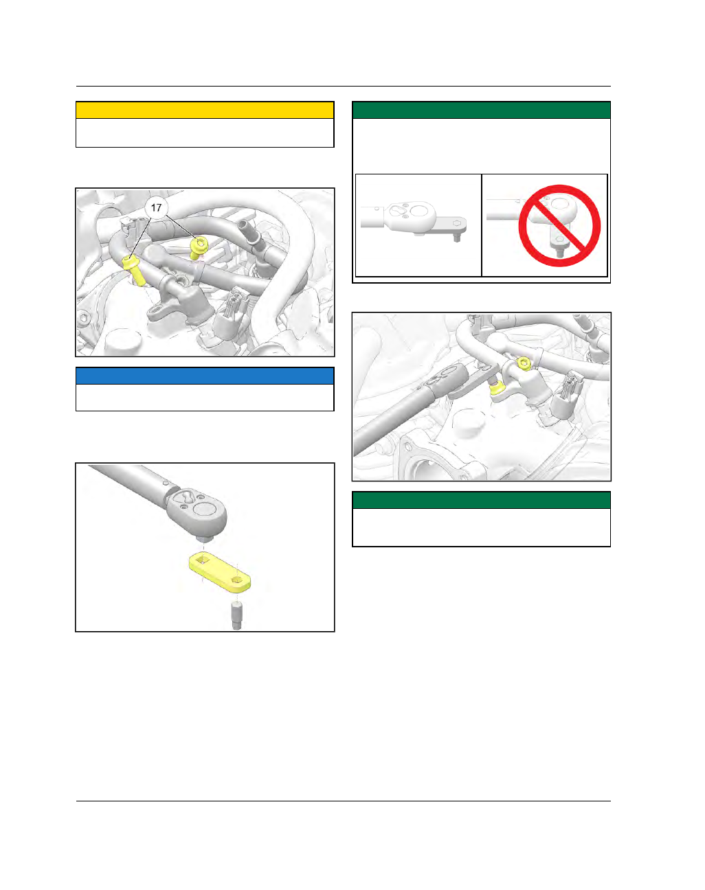
5. Install fuel rail fasteners

k

into the intake manifold

until finger tight.

NOTE

For ease of installation, install the front cylinder fuel

rail fastener first.

6. Install the FUEL RAIL TORQUE TOOL (5264374)

onto a ¼ in drive torque wrench. Install a 5 mm
allen bit to the hex end of the torque tool as shown.

IMPORTANT

Alignment of the special tool is critical to achieve the

correct torque. Make sure the FUEL RAIL TORQUE

TOOL remains in-line with the torque wrench while

torquing fasteners.

7. Torque fuel rail fasteners to specification.

IMPORTANT

Make sure the FUEL RAIL TORQUE TOOL and the

torque wrench remain in-line while torquing

fasteners.

FUEL DELIVERY / EFI

4

4.45

TORQUE

Fuel Rail Fasteners:

74 in-lbs (8 Nm)

8. Squeeze the quick connect buttons (one on each

side) and hold. Remove special tool from fuel line.

NOTE

Use a rag to contain the small amount of fuel that may

drain from the fuel line after the special tool is

removed.

9. Connect fuel line to fuel rail.

NOTE

Listen for an audible “click” to confirm the line is

fully engaged.

IMPORTANT

Pressurize the fuel system by powering up the bike

and slide the STOP/RUN switch to the RUN position.

Verify no leaks present with system under pressure.

10. Uncover the intake

h

.

11.

IMPORTANT

Verify that BOTH air box o-ring seals are correctly in

position before installing the throttle body.

12. Feed

the

throttle

body

multi-plug

connector

through the hole in the air box. Connect intake
hose to the air box housing.

FUEL DELIVERY / EFI

4.46

9927618 R03 - 2017 Indian Motorcycle (Full-Size) Service Manual

NOTE

Use a small amount of lubricant around the outside of

the breather hose when installing to the air box

housing.

NOTE

Make sure that the harness seal is fully seated in the

air box cutout.

13. Install four throttle body fasteners

g

. Torque

fasteners to specification.

TORQUE

Throttle Body Fasteners:

84 in-lbs (10 Nm)

14. Connect the multi-plug

f

to the throttle body.

15. Install the lower fastener

d

securing the air box to

the

mounting

plate.

Torque

fastener

to

specification.

FUEL DELIVERY / EFI

4

4.47

TORQUE

Air Box Fastener:

31 in-lbs (4 Nm)

16. Install the upper two fasteners

s

securing the

baffle plate to the intake. Torque fasteners to
specification.

TORQUE

Upper Intake Fasteners:

84 in-lbs (10 Nm)

17. Install the three air filter adapter plate fasteners

a

.

Torque fasteners to specification.

18. Install the three fasteners

o

securing the air filter

to

the

adapter

plate.

Torque

fasteners

to

specification.

FUEL DELIVERY / EFI

4.48

9927618 R03 - 2017 Indian Motorcycle (Full-Size) Service Manual

TORQUE

Air Filter Fasteners:

62 in-lbs (7 Nm)

19. Install the three fasteners

i

securing the air

cleaner cover to the air box. Torque fasteners to
specification.

TORQUE

Air Box Cover Fasteners:

84 in-lbs (10 Nm)

20. Verify that both fuel tank isolators are assembled

correctly as shown.

21. Remove the small 2x4 piece of wood beneath the

fuel tank rear mount and lower fuel tank into
position. Install fuel tank fasteners

u

. Torque

fasteners to specification.

FUEL DELIVERY / EFI

4

4.49

TORQUE

Fuel Tank Fasteners:

84 in-lbs (10 Nm)

22. Slide front of seat into seat retaining bracket. Install

the two fasteners

y

retaining the driver seat to the

frame. Torque seat fasteners to specification

TORQUE

Seat Fasteners:

84 in-lbs (10 Nm)

NOTE

For models with a passenger seat, install and torque

passenger seat fastener.

23. Connect the motorcycle to Digital Wrench. Verify

no fail codes and no MIL lights are present. Field
Test the motorcycle to verify proper operation.

24. Install the upper side covers.

25. Install Trunk (if equipped). See Trunk Installation,

Roadmaster, page 7.30

26. Install Saddlebags (if equipped).

FUEL DELIVERY / EFI

4.50

9927618 R03 - 2017 Indian Motorcycle (Full-Size) Service Manual

CCRRAANNKKSSHHAAFFTT PPOOSSIITTIIOONN SSEENNSSOORR,, TTEESSTT // RREEPPLLAACCEE

CPS Test

1. Locate the CPS connector

q

behind the RH front

down tube, and disconnect.

2. Connect an ohmmeter between the pin terminals

w

and

compare

resistance

readings

to

specification below.

3. If resistance is correct, check to see that the sensor

is mounted properly and that the tone wheel has
not been damaged and is securely mounted to the
crankshaft assembly.

Crankshaft Position Sensor:

860 Ohms @ 20°C (68°F)

CPS Replacement

1. Remove starter motor. See Starter Motor, Removal /

Installation, page 10.25.

2. Remove regulator / rectifier assembly and bracket.

See Rectifier / Regulator Replacement, page 10.33.

3. Disconnect the CPS sensor from the vehicle

harness and release flying lead from plastic darts
and cable ties.

4. Remove the fastener

e

securing the CPS sensor to

the engine case and remove sensor.

5.

Installation is performed by reversing the
removal procedure.

NOTE

Apply rubber lubricant to the CPS sensor o-ring to

ease installation.

6. Torque the CPS retaining fastener to specification.

TORQUE

Crankshaft Position Sensor Retaining Fastener:

89 in-

lbs (10 Nm)

FUEL DELIVERY / EFI

4

4.51

DDEETTOONNAATTIIOONN SSEENNSSOORR TTEESSTT // RREEPPLLAACCEE

The detonation, or “Knock” sensor is a piezoelectric
sensor that advances or retards ignition based on
load.

CAUTION

The detonation sensor is torque sensitive and must

be replaced if removed for any reason.

IMPORTANT

The detonation sensor must be torqued to

specification or it will not perform correctly. Sensors

that have been over-tightened or under-tightened

may set a diagnostic trouble code and cause the MIL

to illuminate. Use a properly calibrated torque

wrench during installation.

Detonation Sensor Diagnostic Information

COMPONENT

LOCATION

P-CODE

SPN

FMI

DESCRIPTION

Detonation

“Knock” Sensor

Rearward

face of the

front cylinder

P0327

731

4

Knock Sensor 1: Voltage too low

P1327

520331

3

Positive Line: Voltage too high

P1328

4

Positive Line: Voltage too low

P132A

520332

3

Negative Line: Voltage too high

P132B

4

Negative Line: Voltage too low

Test 1

1.

Disconnect

the

negative

battery

cable.

See

Battery, Removal, page

.

2.

With the RH upper side cover removed, locate the
detonation sensor connector

q

just inside the RH

midcasting and disconnect.

3.

Inspect the sensor-side of the connector for
moisture and / or corrosion. Make sure the
terminal pins are securely seated in the plug.

4.

Remove the ECM from the motorcycle to access
ECM connector 2. See ECM Removal / Installation,
page 4.35.

5.

Set multi meter to measure resistance.

6.

Measure the resistance through each wire from
ECM

connector

to

the

sensor

connector.

Resistance should be less than 1 Ohm (good
continuity). See ECM Connector MAP, page 4.24
for pin locations.

ECM2 Pin 37 to Detonation Sensor Connector Pin 1

should be less than 1

Ω

.

ECM2 Pin 38 to Detonation Sensor Connector Pin 2

should be less than 1

Ω

.

7.

Measure the resistance across the detonation
sensor pins 1 & 2.

Resistance across Detonation Sensor Connector Pin 1

& Pin 2: Continuity

Resistance should be between 4.5–5.0 M

Ω

8.

If the resistance does not match the specified
value, replace the sensor.

Test 2

9.

Using a multi meter with a low voltage AC
frequency scale, connect the meter leads to the
connector pins of the detonation sensor.

10. Allow the signal to stabilize to 0 Hz.

11. Lightly tap the front cylinder near the knock

sensor with a rubber mallet or other non-metallic
object.

12. Watch for frequency fluctuation.

13. If no frequency fluctuation is observed while

tapping on the cylinder, replace the sensor.

Replace

FUEL DELIVERY / EFI

4.52

9927618 R03 - 2017 Indian Motorcycle (Full-Size) Service Manual

14. Remove the ignition coil assembly and mounting

bracket. See Ignition Coil Removal / Installation,
page 10.40.

15. Remove the fuel tank. See Fuel Tank Removal,

page 4.15.

16. Remove the fastener

w

securing the detonation

sensor to the forward cylinder.

17. Noting how the detonation sensor harness is

routed, remove the sensor from the motorcycle.

18.

INSTALLATION is performed by reversing the
removal procedure.

19. Torque

the

detonation

sensor

fastener

to

specification.

TORQUE

Detonation Sensor Fastener:

15 ft-lbs (20 Nm)

TTHHRROOTTTTLLEE BBOODDYY ((EETTCC)) RREEM

MOOVVAALL

1.

To

remove

the

Electronic

Throttle

Control

assembly, see Air Box Removal, page 3.4.

FUEL DELIVERY / EFI

4

4.53

CCYYLLIINNDDEERR M

MIISSFFIIRREE DDEETTEECCTTIIOONN

The ECU monitors crankshaft speed via the crankshaft position sensor. A misfire will cause a fluctuation in
crankshaft speed. A code will set and flash the check engine light after an engine misfire threshold/rate is
detected that is above a pre-determined limit. This threshold varies based on engine speed.

One or more of the following codes will be set if a misfire occurs:

• P0301 (SPN 65591/FMI 7) Misfire Detected, Cylinder 1 (Front)
• P0302 (SPN 65592/FMI 7) Misfire Detected, Cylinder 2 (Rear)
• P0314 (SPN 65590/FMI 7) Misfire Confirmed

If a misfire is detected, the following events will occur:

• The check engine indicator lamp will begin to flash and fuel will be cut to the affected cylinder(s). The check

engine indicator lamp will continue to flash until the ignition switch has been moved to the off position.
Restarting the engine will clear the flashing indicator and restore fuel to both cylinders.

• If a 2

nd

misfire occurs, the check engine indicator lamp will resume flashing and fuel will once again be cut to

the affected cylinder(s).

• After the 3

rd

misfire, P0314 misfire fault is determined & set, the check engine light will remain on and fuel will

be cut to the affected cylinder(s). If this occurs, follow the troubleshooting section below.

In cases where cylinder misfire is intermittent, or has been repaired in the field (e.g. loose spark plug wire has
been reattached), Misfire Detection utilizes a self-healing feature to allow continued operation. Following the 1st
or 2nd misfire event, when the ignition is cycled OFF and ON again, the misfire code becomes historic and the
MIL turns off. When P0314 is set, after the 3rd misfire event, the MIL will stay on for 3 fault free drive cycles before
turning off.

If the MIL turned on solid due to P0314, it will stay on until the misfire condition has been removed and 3 fault free
drive cycles have occurred.

NOTE

DRIVE CYCLE:

A drive cycle consists of cycling the ignition from OFF to ON, then start the engine and run at idle for a period of

approximately 4 minutes. Finally, turn off the ignition for approximately 2 1/2 minutes.

If it does not turn off, diagnose by verifying the following items:

TROUBLESHOOTING

• Ignition Coil and connections are good
• Spark plugs wires are secure
• The correct spark plugs are installed and the plugs are not fouled
• Crankshaft Position Sensor tests good
• Wiring to the Crankshaft Position Sensor, ECU and Ignition Coil are not damaged. Chassis ground is clean

and tight

• Fuel pressure is within specification
• Fresh/good quality fuel is in the fuel tank
• Engine mechanical is good (leak down, timing)

IMPORTANT

Once the systems is repaired and functioning normally, connect to Digital Wrench to clear active and historic

codes. Retest to verify the condition is no longer present.

FUEL DELIVERY / EFI

4.54

9927618 R03 - 2017 Indian Motorcycle (Full-Size) Service Manual

CCAANN DDIIAAGGNNOOSSTTIICCSS

CCAANN ((CCOONNTTRROOLLLLEERR AARREEAA NNEETTW

WOORRKK))

DDIIAAGGNNOOSSTTIICC OOVVEERRVVIIEEW

W

Overview

The speedometer and Engine Control Module (ECM)
have integrated 120

Ω

termination resistors. With the

speedometer unplugged, check resistance between
the CAN terminals at the speedometer connector. The
resistance should be 120

Ω

. With the speedometer

connector plugged in, and the ECM connector
unplugged

the

resistance

will

be

120

Ω

.

With

speedometer and ECM connectors plugged in, the
resistance will be 60

Ω

Baseline CAN Resistance Values

Checking resistance between Yellow CAN High wire
and Green CAN Low wire at the specified module
connectors below (while unplugged):

• VCM = 60

Ω

• ECM = 120

Ω

• Speedometer = 120

Ω

• ABS Module = 60

Ω

• Diagnostic Connector = 60

Ω

FUEL DELIVERY / EFI

4

4.55

DDIIGGIITTAALL W

WRREENNCCHH

DDIIGGIITTAALL W

WRREENNCCHH DDIIAAGGNNOOSSTTIICC SSOOFFTTW

WAARREE

OOVVEERRVVIIEEW

W

NOTE

Refer to Section 2, 3 and 4 in the Instruction Manual

provided in the Digital Wrench Diagnostic Kit to

install the Digital Wrench diagnostic software on your

computer.

The Digital Wrench diagnostic software allows the
technician

to

perform

the

following

tests

and

observations:

• View or clear trouble codes
• Analyze real-time engine data
• Reflash ECU calibration files
• Perform guided diagnostic procedures
• Create customer service account records
• Perform output state control tests (some models)

DDIIAAGGNNOOSSTTIICC SSOOFFTTW

WAARREE VVEERRSSIIOONN

Always use the most current version of the Digital
Wrench software to ensure you have the latest updates
or enhancements. New reprogramming files and
guided diagnostic procedures are added to these
updates as they become available. For information on
how to determine if you have the latest update
available, see Digital Wrench Version and Update ID,
page 4.56.

EECCM

M RREEPPLLAACCEEM

MEENNTT

Although the need for ECM replacement is unlikely, a
specific replacement procedure is required to ensure
that all essential data contained within the original
ECU is transferred to the replacement ECU.

Refer to procedure and carefully follow all instructions
provided in Digital Wrench.

GGUUIIDDEEDD DDIIAAGGNNOOSSTTIICC AAVVAAIILLAABBLLEE

Guided

diagnostics

are

available

within

Digital

Wrench for most supported Diagnostic Trouble Codes
(DTCs). That is, any fault that will turn on the ‘Check
Engine’ indicator.

In addition, guided diagnostics are also available for
many other electrical sub systems.

Diagnostic procedures are added to subsequent
versions of Digital Wrench as they become available.
Check your release version often and upgrade when
available to be sure you are using the most current
software available.

DDIIGGIITTAALL W

WRREENNCCHH CCOOM

MM

MUUNNIICCAATTIIOONN EERRRROORRSS

If you experience problems connecting to a vehicle or
any other Digital Wrench related problem, visit the
Digital Wrench Knowledge Base for the most current
troubleshooting information, FAQs, downloads and
software updates at:

http://polaris.diagsys.com/.

FUEL DELIVERY / EFI

4.56

9927618 R03 - 2017 Indian Motorcycle (Full-Size) Service Manual

DDIIGGIITTAALL W

WRREENNCCHH DDIIAAGGNNOOSSTTIICC CCOONNNNEECCTTOORR

The diagnostic connector

q

is located under the LH

upper side cover, below the fuse box.

Follow these steps to connect the diagnostic interface
cable to the vehicle:

1.

Assemble the SmartLink Module and attach the PC
Interface Cable to your laptop.

2.

Unplug the Digital Wrench connector from it’s
protective receptacle.

3.

Connect the Vehicle Interface Cable to the Digital
Wrench diagnostic connector.

4.

Press the ON button to power up the motorcycle
electrical system and switch the STOP / RUN
switch to the RUN position.

5.

Select the appropriate vehicle and wait for the
status to display ‘Connected’ in the lower left
corner of the screen.

6.

Once connected, proceed with using Digital
Wrench.

DDIIGGIITTAALL W

WRREENNCCHH SSEERRIIAALL NNUUM

MBBEERR LLOOCCAATTIIOONN

Open the configuration screen by clicking on the
wrench icon. The serial number is located on the right
side of the screen.

DDIIGGIITTAALL W

WRREENNCCHH VVEERRSSIIOONN AANNDD UUPPDDAATTEE IIDD

Knowing what Digital Wrench version and update is
installed will help determine which updates are
required.

NOTE

Versions and updates are subject to change.

1.

Open the Digital Wrench software. Locate the
version ID shown on the lower right side of the
Digital Wrench start-up screen.

2.

Proceed to

http://polaris. diagsys. com

to see if a

newer update is available.

3.

If a newer update is available, it should be
downloaded before using Digital Wrench.

NOTE

Always operate with the latest update.

FUEL DELIVERY / EFI

4

4.57

DDIIGGIITTAALL W

WRREENNCCHH UUPPDDAATTEESS

Updates are released for Digital Wrench via the
Internet at:

http://polaris. diagsys. com

. The Digital

Wrench website can also be accessed through the
dealer website at:

www.polarisdealers.com

.

NOTE

Only authorized Indian Motorcycle dealers and

distributors can access the dealer website.

1.

Log on to

www.polarisdealers.com

.

2.

Locate the

Service and Warranty

drop-down

menu.

3.

Click on

Digital Wrench Updates

.

4.

The Digital Wrench portal website should appear
in a new web browser.

5.

Click on

Digital Wrench Version Updates

.

NOTE

You must already have the current version installed

before adding an update. Updates will not install if

you are using an older version loaded on your PC.

6.

If the update file date listed is newer than your
current version and update, download the file.

7.

Click on the link shown above, save the file to your
hard disk and then double-click the icon to start
the update process.

NOTE

Do not "run" or "open" the file from where they are.

Select "save" and download them to your PC before

running the install.

8.

When the update is complete, the version shown
on the right side of the Digital Wrench start-up
screen

should

match

the

update

you

just

downloaded.

NOTE

Versions and updates are subject to change.

FUEL DELIVERY / EFI

4.58

9927618 R03 - 2017 Indian Motorcycle (Full-Size) Service Manual

DDIIGGIITTAALL W

WRREENNCCHH FFEEAATTUURREE M

MAAPP

FUEL DELIVERY / EFI

4

4.59

EENNGGIINNEE CCOONNTTRROOLLLLEERR RREEPPRROOGGRRAAM

MM

MIINNGG

((RREEFFLLAASSHH))

Process Overview

The reprogramming feature is in the Special Tests
menu on the Digital Wrench screen. Start Digital
Wrench and click on the Special Tests menu icon (red
tool box). A technician should be familiar with the
process and with computer operation in general
before attempting to reprogram an ECM.

The

Digital

Wrench

Engine

Controller

Reprogramming

(or

“Reflash”)

feature

allows

reprogramming of the ECM fuel and ignition map. To
successfully reprogram the ECM, an Authorization Key
must be obtained by entering a Request Code in the
box provided on the Reflash Authorization site. The
Request Code is automatically generated by Digital
Wrench during the reprogramming process. The
Reflash Authorization site is located under the

Service

and Warranty

drop down menu on the dealer website

at:

www.polarisdealers.com

.

NOTE

Failure to follow the reprogramming instructions

completely and correctly can result in an engine that

does not run! Replacement ECMs are programmed

as “no-start” and require a reflash for them to work.

Reprogramming (Reflash) Tips:

• BATTERY VOLTAGE: The majority of problems with

reprogramming can be attributed to a low battery.
Be sure the battery voltage (no load) is at least 13
volts and at least 12.5 volts with the key ‘ON’.
Connect a battery charger if necessary to bring
voltage level above minimum. Fully charge the
battery before you attempt to reprogram.

• DEDICATED LAPTOP: Best results are obtained

using a laptop computer that is “dedicated to Digital
Wrench”. A laptop that is used by a variety of
people and in several applications around the
dealership is more likely to cause a reprogramming
problem than one dedicated to Digital Wrench
diagnostics only.

• OBTAINING THE LATEST UPDATE: Reprogramming

updates are provided periodically and contain the
most recent calibrations.

• CLOSE NON-ESSENTIAL PROGRAMS: It is

recommended that you DO NOT install non-essential
programs on a Service Department laptop. Camera
detection software, Virus Scanners, Tool Bars, etc.
may clog up memory if running in the background
and make it harder for the diagnostic software to
operate.

• KNOW THE PROCESS: If you are not familiar with the

entire reprogramming process, review the HELP
section of the diagnostic software before you
attempt reprogramming. Click on the

?

on the tool

bar or press F11. The information in the on-line help
is the most current and complete information
available. This should be your first step until you are
familiar with the process.

• COMMUNICATION PROBLEMS: If you have had

problems communicating with a vehicle while
performing diagnostic functions, do not attempt
reprogramming until the cause has been identified
and fixed. Check all connections, and be sure
battery voltage is as specified.

• Proceed to

http://polaris.diagsys.com

for specific

information and FAQs on how to troubleshoot
communication problems.

• DON’T DISTURB THE PC: While reprogramming is in

progress, don’t move the mouse and don’t touch the
keyboard. The process only takes a few minutes,
and is best left alone until complete.

Reprogramming (Reflash) Procedure:

If you are not familiar with the reprogramming
process, review the “Reprogramming (Reflash) Tips”
before you begin. Follow the on-screen instructions as
you progress through the steps. If you encounter a
problem, always check the On-Line help for current
tips and information.

1.

Verify

the

most

current

update

has

been

downloaded and loaded into Digital Wrench.

2.

Connect SmartLink Module cables to PC and
vehicle.

3.

Open the Digital Wrench program.

4.

Select the model year, product line and vehicle
description by selecting the “Change Vehicle
Type” icon.

5.

Select the “Special Tests” icon.

6.

Select “Engine Controller Reprogramming”.

7.

Select the file you want to load into the ECU then
click the “Continue” icon to proceed to the
Integrity Check and obtain a Request Code.

8.

Copy (CTRL +C) the Request Code that will be
required on the dealer website in the next step.
DO NOT CLOSE Digital Wrench or the Request
Code will be invalid.

NOTE: All characters are

letters; there are no numbers in a request code.

NOTE

Request Codes and Authorization Keys must be

entered EXACTLY as they appear on the screen.

FUEL DELIVERY / EFI


Content      ..     14      15      16      17     ..